EP1288023A1 - Geländegängiger Reifen - Google Patents
Geländegängiger Reifen Download PDFInfo
- Publication number
- EP1288023A1 EP1288023A1 EP02019048A EP02019048A EP1288023A1 EP 1288023 A1 EP1288023 A1 EP 1288023A1 EP 02019048 A EP02019048 A EP 02019048A EP 02019048 A EP02019048 A EP 02019048A EP 1288023 A1 EP1288023 A1 EP 1288023A1
- Authority
- EP
- European Patent Office
- Prior art keywords
- blocks
- tread
- tire
- shoulder
- central
- Prior art date
- Legal status (The legal status is an assumption and is not a legal conclusion. Google has not performed a legal analysis and makes no representation as to the accuracy of the status listed.)
- Granted
Links
Images


Classifications
-
- B—PERFORMING OPERATIONS; TRANSPORTING
- B60—VEHICLES IN GENERAL
- B60C—VEHICLE TYRES; TYRE INFLATION; TYRE CHANGING; CONNECTING VALVES TO INFLATABLE ELASTIC BODIES IN GENERAL; DEVICES OR ARRANGEMENTS RELATED TO TYRES
- B60C11/00—Tyre tread bands; Tread patterns; Anti-skid inserts
- B60C11/03—Tread patterns
- B60C11/0318—Tread patterns irregular patterns with particular pitch sequence
-
- B—PERFORMING OPERATIONS; TRANSPORTING
- B60—VEHICLES IN GENERAL
- B60C—VEHICLE TYRES; TYRE INFLATION; TYRE CHANGING; CONNECTING VALVES TO INFLATABLE ELASTIC BODIES IN GENERAL; DEVICES OR ARRANGEMENTS RELATED TO TYRES
- B60C11/00—Tyre tread bands; Tread patterns; Anti-skid inserts
- B60C11/03—Tread patterns
- B60C11/0327—Tread patterns characterised by special properties of the tread pattern
- B60C11/033—Tread patterns characterised by special properties of the tread pattern by the void or net-to-gross ratios of the patterns
-
- B—PERFORMING OPERATIONS; TRANSPORTING
- B60—VEHICLES IN GENERAL
- B60C—VEHICLE TYRES; TYRE INFLATION; TYRE CHANGING; CONNECTING VALVES TO INFLATABLE ELASTIC BODIES IN GENERAL; DEVICES OR ARRANGEMENTS RELATED TO TYRES
- B60C11/00—Tyre tread bands; Tread patterns; Anti-skid inserts
- B60C11/03—Tread patterns
- B60C11/11—Tread patterns in which the raised area of the pattern consists only of isolated elements, e.g. blocks
-
- B—PERFORMING OPERATIONS; TRANSPORTING
- B60—VEHICLES IN GENERAL
- B60C—VEHICLE TYRES; TYRE INFLATION; TYRE CHANGING; CONNECTING VALVES TO INFLATABLE ELASTIC BODIES IN GENERAL; DEVICES OR ARRANGEMENTS RELATED TO TYRES
- B60C9/00—Reinforcements or ply arrangement of pneumatic tyres
- B60C9/02—Carcasses
- B60C9/04—Carcasses the reinforcing cords of each carcass ply arranged in a substantially parallel relationship
- B60C9/06—Carcasses the reinforcing cords of each carcass ply arranged in a substantially parallel relationship the cords extend diagonally from bead to bead and run in opposite directions in each successive carcass ply, i.e. bias angle ply
-
- B—PERFORMING OPERATIONS; TRANSPORTING
- B60—VEHICLES IN GENERAL
- B60C—VEHICLE TYRES; TYRE INFLATION; TYRE CHANGING; CONNECTING VALVES TO INFLATABLE ELASTIC BODIES IN GENERAL; DEVICES OR ARRANGEMENTS RELATED TO TYRES
- B60C2200/00—Tyres specially adapted for particular applications
- B60C2200/10—Tyres specially adapted for particular applications for motorcycles, scooters or the like
-
- B—PERFORMING OPERATIONS; TRANSPORTING
- B60—VEHICLES IN GENERAL
- B60C—VEHICLE TYRES; TYRE INFLATION; TYRE CHANGING; CONNECTING VALVES TO INFLATABLE ELASTIC BODIES IN GENERAL; DEVICES OR ARRANGEMENTS RELATED TO TYRES
- B60C2200/00—Tyres specially adapted for particular applications
- B60C2200/14—Tyres specially adapted for particular applications for off-road use
Definitions
- the present invention relates to a pneumatic tire, more particularly to a block pattern tire for use in rough terrain having an improved block arrangement.
- motorcycle tires for use in rough terrain such as motocross tires are generally provided with block-type tread pattern whose negative ratio is over 50 % for traction in soft terrain such as mud traction.
- the tread camber is very high in comparison with other kinds of tires such as passenger car tire, truck/bus tire and the like, and mud is liable to accumulate in the tread shoulder region during straight running. Therefore, when the running condition changes from straight running to cornering, due to the accumulate mud, road grip and traction are decreased, and control of the machine is liable to be lost.
- an object of the present invention to provide a pneumatic tire for use in rough terrain, in which, by improving the arrangement of tread blocks, mud accumulation, traction and the like can be improved, and a running performance change when the running condition changes from straight running to cornering or vice versa is decreased.
- a pneumatic tire comprises a tread comprising central blocks, shoulder blocks and intermediate blocks, in the tread which is developed in a plane, the central blocks are arranged circumferentially of the tire at substantially constant pitch lengths P1, the intermediate blocks in each of the intermediate regions are arranged circumferentially of the tire at substantially constant pitch lengths P2, and the shoulder blocks in each of the shoulder regions are arranged circumferentially of the tire at substantially constant pitch lengths P3, in a certain number (K) of circumferential positions, the central blocks are aligned with the intermediate blocks in the tire axial direction, wherein the number (K) is in a range of from 6 to 32, the circumferential positions are provided circumferentially of the tire at regular intervals equal to the pitch length P1 multiplied by an integral number (n), wherein the number (n) is in a range of from 3 to 8, the pitch length P2 and pitch length P3 are equal to the pitch length P1 multiplied by n/(n-1) or n/(n-2), wherein the
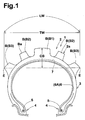
- Fig.1 is a cross sectional view of a motorcycle tire according to the present invention.
- Fig.2 is a view showing the developed tread portion thereof.
- Fig.3 is a view showing the developed tread portion of a tire used in the undermentioned comparison test.
- pneumatic tire 1 according to the present invention comprises a tread portion 2 with tread edges E, a pair of sidewall portions 3, a pair of axially spaced bead portions 4 each with a bead core 5 and a rubber bead apex 8 therein, and a carcass 6 extending between the bead portions 4.
- the tire 1 is a motorcross motorcycle tire whose tread portion 2 is curved so that the maximum tire width TW lies between the tread edges E.
- the tread camber is in a range of 0.2 to 0.45, usually in a range of 0.25 to 0.35 (in this example about 0.26).
- the carcass 6 in this example has a bias structure comprising two or three plies of cords rubberized with topping rubber, including at least two cross plies 6A.
- Each ply 6A extends between the bead portions 4 and is turned up around the bead core 5 in each of the bead portions 4 from the inside to the outside of the tire and then extends radially outwardly on the axially outside of the bead core 5 and bead apex 8 so as to form a pair of turnup portions and a main portion therebetween.
- the cords in each of the cross plies 6A are inclined at an angle in a range of from 75 to 45 degrees with respect to the tire equator.
- the cord angle of one ply 6A is substantially the same as the cord angle of the other ply 6A, but their inclining directions are opposite to each other with respect to the tire equator.
- organic fiber cords e.g. nylon, polyester, rayon, aromatic polyamide and the like can be used.
- a breaker 7 is disposed radially outside the carcass 6.
- the breaker 7 is composed of one or two plies of cords laid at an angle of from 15 to 45 degrees with respect to the tire equator.
- the tread 2a comprises a plurality of blocks B.
- the top face Ba of the block B is a polygon, and more preferably the block B has axially extending edges and circumferentially extending edges which are straight or almost straight.
- each block B is provided with a substantially rectangular top face Ba.
- the height of the blocks B is set in a range of from 6 to 18 mm. In this particular case, the height is preferably set in a range of from 13 to 18 mm.
- the tread portion 2 in order to form a plurality of blocks B, can be provided with various kinds of tread grooves in a more distinct form such as circumferential groove and axial groove.
- the land/sea ratio of the tread 2a is set in a range of from 10 to 50 %.
- the land/sea ratio (L/S) is, as well known in the art, the ratio of the land area (ground contacting area) to the sea area (non-contacting area) of the tread 2a.
- the land area (L) is the total area of the top faces of the blocks B.
- the sea area (S) is equal to the overall area of the tread 2a minus the land area (L). If the land/sea ratio (L/S) is less than 10 %, traction and cornering performance in hard terrain and medium terrain are liable to deteriorate.
- the land/sea ratio (L/S) is more than 50 %, the traction in soft terrain decreases. However, it is also possible to set the land/sea ratio according to the running conditions. If running is mainly in hard terrain, the land/sea ratio (L/S) is preferably set in a range of 22 to 50 %. If running is mainly in soft terrain, the land/sea ratio is preferably set in a range of 10 to 22 %. In case of medium terrain, the land/sea ratio is preferably set in a range of 20 to 24 %.
- the blocks B include central blocks B1, intermediate blocks B2 and shoulder blocks B3.
- the central block B1 is defined such that at least 80 % of the ground contacting area of the top face Ba of the block is within a central region A1 of the tread 2a.
- the intermediate block B2 is defined such that at least 80 % of the ground contacting area of the top face Ba of the block is within an intermediate region A2 of the tread 2a.
- the shoulder block B3 is defined such that at least 80 % of the ground contacting area of the top face Ba of the block is within a shoulder region A3 of the tread 2a.
- the tread 2a is defined between the tread edges E, and the regions A1, A2 and A3 are defined as follows.
- the central region A1 is centered on the tire equator C and has a width of 25 % of the tread width Lw along the curved tread 2a or tread profile line.
- the shoulder region A3 extends from each of the tread edges E to have a width of 12.5 % of the tread width LW along the curved tread 2a.
- the intermediate region A2 is defined as being between the central region A1 and each shoulder region A3 and accordingly having a width of 25 % of the tread width LW along the curved tread 2a.
- the blocks B are arranged circumferentially of the tire at substantially constant pitch lengths P(P1,P2,P3) so that the position of the block B does not shift more than 8 mm in the tire circumferential direction from the regular circumferential positions J at regular intervals of constant pitch lengths P.
- the position of the block B may be defined as that of the centroid of the block top Ba. This also means that the pitch length P can be found by dividing a circumference by a number of blocks existing in the region.
- the central blocks B1 are arranged circumferentially at substantially constant pitch lengths P1.
- the intermediate blocks B2 are arranged circumferentially at substantially constant pitch lengths P2.
- the shoulder blocks B3 are arranged circumferentially at substantially constant pitch lengths P3.
- the central blocks B1 and intermediate blocks B2 align with each other in the tire axial direction.
- the aligning position 11 one of the central blocks B1, one of the intermediate blocks B2 in one of the intermediate regions A2 and one of the intermediate blocks B2 in the other intermediate region A2 are aligned with each other in the tire axial direction.
- the aligning positions 11 are provided circumferentially of the tire at regular intervals of (n) times the pitch length P1.
- the number (n) is an integral number in a range of from 3 to 8, preferably 4 to 6.
- the number (K) of the aligning positions 11 is in a range of from 6 to 32.
- the positions of the blocks B1 and B2 are exactly aligned, but it is not always necessary. Such rough alignment that the circumferential shift between the block positions are less than 8 mm may be permitted.
- the pitch length P2 is increased such that the pitch length P2 becomes equal to the pitch length P1 multiplied by n/(n-1) or n/(n-2).
- the number N1 of the pitches P1 is equal to the above-mentioned number (n)
- the number N2 of the pitches P2 is 1 or 2 less than the number N1.
- the intermediate blocks B2 and the shoulder blocks B3 on each side of the tire equator C are staggered to provide steering stability during cornering in hard terrain.
- the aligning positions 11 By the aligning positions 11, traction in soft terrain can be effectively improved. If the number (K) of the aligning positions 11 is less than 6, it becomes difficult to improve the traction. If the number (K) is more than 32, running performance in hard and medium terrain is liable to deteriorate although the traction in soft terrain may be improved. If the number (n) is less than 3, then the aligning positions 11 are increased in the number (K) or the blocks B1 are increased in the size. In the former case, the running performance in hard terrain deteriorates. In the later case, the traction in soft terrain decreases. If the number (n) is more than 8, then the aligning positions 11 are decreased in the number (K) or the blocks B1 are increased in the size. In the former case, the traction in soft terrain is decreased. In the later case, as the block rigidity decreases, running performance in hard terrain deteriorates.
- the pitch number N2, N3 one or two smaller than the pitch number N1
- the difference in the land/sea ratio between the central region A1 and intermediate region A2 and the difference in the land/sea ratio between the intermediate region A2 and shoulder region A3 can be minimized.
- a change in running performance from straight running to cornering can be decreased to provide steering stability.
- mud accumulation in the sea area of the intermediate region A2 and shoulder region A3 and traction in these regions can be improved, which further improves the running performance change.
- the pitch number difference N1-N2, N1-N3 is more than 2, the blocks in the intermediate region A2 and shoulder region A3 become very few, and it becomes difficult to improve the traction in soft terrain.
- Motocross motorcycle tires (size 110/90-19) having the basic structure shown in Fig.1 were made and tested.
- a 250 cc motorcycle provided on a rear wheel with the test tire was run in a course of rough terrain including hard terrain, medium terrain and soft terrain.
- the test rider evaluated mud accumulation, traction and cornering performance.
- the test results are shown in Table 1 using an index based on Ref. tire being 100, wherein the larger the index number, the better the performance.
- a tire of size 90/100-20 having the tread pattern shown in Fig.3 was mounted in common. Tire Ref.
- the present invention can be also applied to pneumatic tires for three or four wheeled off-road vehicles such as buggy. Further, the present invention can be applied to a radial ply tire in which the carcass cords are arranged at an angle of from 75 to 90 degrees with respect to the tire equator, and one or two belt plies 7 of cords laid at an angle of from 0 to 30 degrees with respect to the tire equator are disposed radially outside the carcass.
Landscapes
- Engineering & Computer Science (AREA)
- Mechanical Engineering (AREA)
- Tires In General (AREA)
Applications Claiming Priority (2)
| Application Number | Priority Date | Filing Date | Title |
|---|---|---|---|
| JP2001264197A JP4037629B2 (ja) | 2001-08-31 | 2001-08-31 | 不整地走行用の空気入りタイヤ |
| JP2001264197 | 2001-08-31 |
Publications (2)
| Publication Number | Publication Date |
|---|---|
| EP1288023A1 true EP1288023A1 (de) | 2003-03-05 |
| EP1288023B1 EP1288023B1 (de) | 2009-10-14 |
Family
ID=19090845
Family Applications (1)
| Application Number | Title | Priority Date | Filing Date |
|---|---|---|---|
| EP02019048A Expired - Fee Related EP1288023B1 (de) | 2001-08-31 | 2002-08-27 | Geländegängiger Reifen |
Country Status (6)
| Country | Link |
|---|---|
| US (1) | US6799617B2 (de) |
| EP (1) | EP1288023B1 (de) |
| JP (1) | JP4037629B2 (de) |
| CN (1) | CN1278878C (de) |
| ES (1) | ES2332038T3 (de) |
| TW (1) | TW533146B (de) |
Cited By (4)
| Publication number | Priority date | Publication date | Assignee | Title |
|---|---|---|---|---|
| EP1792753A1 (de) * | 2005-11-30 | 2007-06-06 | Sumitomo Rubber Industries Ltd. | Geländereifen |
| WO2008048382A1 (en) * | 2006-10-17 | 2008-04-24 | Bridgestone Firestone North American Tire, Llc | Method for designing the fundamental pitch for a tire tread pattern with variable lug count by rib |
| WO2008124899A1 (en) * | 2007-04-13 | 2008-10-23 | Pirelli Tyre S.P.A | Motorcycle tires and method to improve performance and wear resistance of motorcycle tires |
| CN105593034A (zh) * | 2013-10-28 | 2016-05-18 | 住友橡胶工业株式会社 | 不平整地面行驶用的摩托车用轮胎 |
Families Citing this family (20)
| Publication number | Priority date | Publication date | Assignee | Title |
|---|---|---|---|---|
| US8136562B2 (en) | 2006-12-29 | 2012-03-20 | Bridgestone Firestone North American Tire, Llc | Tire bead insulation |
| EP1992502B1 (de) * | 2007-05-14 | 2010-05-26 | Sumitomo Rubber Industries, Ltd. | Geländegängiger Motorradreifen |
| JP4272244B2 (ja) | 2007-09-13 | 2009-06-03 | 住友ゴム工業株式会社 | 不整地走行用空気入りタイヤ |
| KR101047110B1 (ko) * | 2008-12-04 | 2011-07-07 | 한국타이어 주식회사 | 타이어 패턴의 설계 방법 |
| JP5492012B2 (ja) * | 2010-08-09 | 2014-05-14 | 住友ゴム工業株式会社 | 不整地走行用の自動二輪車用タイヤ |
| JP5039191B2 (ja) * | 2010-08-26 | 2012-10-03 | 住友ゴム工業株式会社 | 不整地走行用の自動二輪車用タイヤ |
| JP5771407B2 (ja) | 2011-02-16 | 2015-08-26 | 株式会社ブリヂストン | 空気入りタイヤ |
| JP5450515B2 (ja) * | 2011-06-10 | 2014-03-26 | 住友ゴム工業株式会社 | 不整地用モーターサイクルタイヤ |
| JP5320491B2 (ja) * | 2011-07-13 | 2013-10-23 | 住友ゴム工業株式会社 | 不整地走行用の自動二輪車用タイヤ |
| CN102795060A (zh) * | 2012-08-16 | 2012-11-28 | 厦门正新橡胶工业有限公司 | 不规则路面使用的自行车充气轮胎 |
| CN103303071B (zh) * | 2013-06-19 | 2016-05-18 | 厦门正新橡胶工业有限公司 | 不平整地面用充气轮胎胎面结构 |
| JP6420674B2 (ja) * | 2015-01-26 | 2018-11-07 | 住友ゴム工業株式会社 | 不整地走行用の自動二輪車用タイヤ |
| WO2017072708A1 (en) * | 2015-10-30 | 2017-05-04 | Pirelli Tyre S.P.A. | Tyre for bicycle wheels |
| CN106114071A (zh) * | 2016-08-26 | 2016-11-16 | 四川远星橡胶有限责任公司 | 一种摩托车用防滑轮胎 |
| WO2018094026A1 (en) | 2016-11-17 | 2018-05-24 | Bridgestone Americas Tire Operations, Llc | Pneumatic tire having dampening element adhered to air barrier layer |
| IT201600117754A1 (it) | 2016-11-22 | 2018-05-22 | Pirelli | Pneumatico per motoveicoli |
| JP7006238B2 (ja) * | 2017-12-19 | 2022-01-24 | 住友ゴム工業株式会社 | タイヤ及びタイヤセット |
| JP7087427B2 (ja) * | 2018-02-08 | 2022-06-21 | 住友ゴム工業株式会社 | 二輪車用タイヤ |
| WO2020223404A1 (en) | 2019-04-29 | 2020-11-05 | Bridgestone Corporation | Sidewall supports for pneumatic tires |
| US11807044B2 (en) * | 2020-03-24 | 2023-11-07 | Sumitomo Rubber Industries, Ltd. | Motorcycle tire for rough terrain |
Citations (5)
| Publication number | Priority date | Publication date | Assignee | Title |
|---|---|---|---|---|
| CH421735A (de) * | 1963-03-02 | 1966-09-30 | Investment In Patent Dev S A R | Allwetter-Kraftfahrzeugreifen |
| US3951191A (en) * | 1973-11-22 | 1976-04-20 | Bridgestone Tire Company Limited | Pneumatic tire for travel on various kinds of grounds |
| EP0324605A2 (de) * | 1988-01-11 | 1989-07-19 | Bridgestone Corporation | Luftreifen |
| JPH0211404A (ja) * | 1988-06-28 | 1990-01-16 | Yokohama Rubber Co Ltd:The | 空気入りタイヤ |
| EP0475929A1 (de) * | 1990-08-22 | 1992-03-18 | Semperit Reifen Aktiengesellschaft | Fahrzeugluftreifen |
Family Cites Families (7)
| Publication number | Priority date | Publication date | Assignee | Title |
|---|---|---|---|---|
| US4267872A (en) * | 1978-04-20 | 1981-05-19 | Honda Giken Kogyo Kabushiki Kaisha | Vehicle tire with tread having circumferentially varying rigidity |
| CA1104046A (en) * | 1978-11-27 | 1981-06-30 | Toshio Hayakawa | Motocross tire for motorcycles |
| JPS6064004A (ja) * | 1983-09-20 | 1985-04-12 | Bridgestone Corp | 接地性にすぐれた不整地走行用タイヤ |
| JP2604822B2 (ja) * | 1988-09-08 | 1997-04-30 | 株式会社ブリヂストン | 不整地用二輪車タイヤ |
| JP3021723B2 (ja) * | 1991-03-25 | 2000-03-15 | 株式会社ブリヂストン | モータサイクルの不整地用タイヤ |
| JP2660950B2 (ja) * | 1992-12-03 | 1997-10-08 | 住友ゴム工業株式会社 | 方向性トレッドを備えた空気入りタイヤ |
| JP3363434B2 (ja) * | 2000-07-21 | 2003-01-08 | 住友ゴム工業株式会社 | 不整地走行用の空気入りタイヤ |
-
2001
- 2001-08-31 JP JP2001264197A patent/JP4037629B2/ja not_active Expired - Fee Related
-
2002
- 2002-08-20 TW TW091118763A patent/TW533146B/zh not_active IP Right Cessation
- 2002-08-26 CN CNB021322007A patent/CN1278878C/zh not_active Expired - Fee Related
- 2002-08-27 EP EP02019048A patent/EP1288023B1/de not_active Expired - Fee Related
- 2002-08-27 ES ES02019048T patent/ES2332038T3/es not_active Expired - Lifetime
- 2002-08-30 US US10/231,201 patent/US6799617B2/en not_active Expired - Lifetime
Patent Citations (5)
| Publication number | Priority date | Publication date | Assignee | Title |
|---|---|---|---|---|
| CH421735A (de) * | 1963-03-02 | 1966-09-30 | Investment In Patent Dev S A R | Allwetter-Kraftfahrzeugreifen |
| US3951191A (en) * | 1973-11-22 | 1976-04-20 | Bridgestone Tire Company Limited | Pneumatic tire for travel on various kinds of grounds |
| EP0324605A2 (de) * | 1988-01-11 | 1989-07-19 | Bridgestone Corporation | Luftreifen |
| JPH0211404A (ja) * | 1988-06-28 | 1990-01-16 | Yokohama Rubber Co Ltd:The | 空気入りタイヤ |
| EP0475929A1 (de) * | 1990-08-22 | 1992-03-18 | Semperit Reifen Aktiengesellschaft | Fahrzeugluftreifen |
Non-Patent Citations (1)
| Title |
|---|
| PATENT ABSTRACTS OF JAPAN vol. 014, no. 147 (M - 0952) 20 March 1990 (1990-03-20) * |
Cited By (5)
| Publication number | Priority date | Publication date | Assignee | Title |
|---|---|---|---|---|
| EP1792753A1 (de) * | 2005-11-30 | 2007-06-06 | Sumitomo Rubber Industries Ltd. | Geländereifen |
| WO2008048382A1 (en) * | 2006-10-17 | 2008-04-24 | Bridgestone Firestone North American Tire, Llc | Method for designing the fundamental pitch for a tire tread pattern with variable lug count by rib |
| WO2008124899A1 (en) * | 2007-04-13 | 2008-10-23 | Pirelli Tyre S.P.A | Motorcycle tires and method to improve performance and wear resistance of motorcycle tires |
| CN105593034A (zh) * | 2013-10-28 | 2016-05-18 | 住友橡胶工业株式会社 | 不平整地面行驶用的摩托车用轮胎 |
| CN105593034B (zh) * | 2013-10-28 | 2017-09-26 | 住友橡胶工业株式会社 | 不平整地面行驶用的摩托车用轮胎 |
Also Published As
| Publication number | Publication date |
|---|---|
| EP1288023B1 (de) | 2009-10-14 |
| US20030047261A1 (en) | 2003-03-13 |
| JP2003072318A (ja) | 2003-03-12 |
| JP4037629B2 (ja) | 2008-01-23 |
| CN1406777A (zh) | 2003-04-02 |
| TW533146B (en) | 2003-05-21 |
| ES2332038T3 (es) | 2010-01-25 |
| US6799617B2 (en) | 2004-10-05 |
| CN1278878C (zh) | 2006-10-11 |
Similar Documents
| Publication | Publication Date | Title |
|---|---|---|
| US6799617B2 (en) | Rough terrain tire | |
| JP5320491B2 (ja) | 不整地走行用の自動二輪車用タイヤ | |
| US8656970B2 (en) | Pneumatic radial tire for motorcycle | |
| US10889149B2 (en) | Pneumatic tire | |
| US7036541B2 (en) | Pneumatic tire | |
| KR101742829B1 (ko) | 부정지 주행용의 자동 이륜차용 타이어 | |
| US6192953B1 (en) | Heavy duty radial tire having tapered shoulder portions | |
| CN110167768B (zh) | 充气轮胎 | |
| EP0861740B1 (de) | Luftreifen für Zweiräder | |
| US6651711B2 (en) | Pneumatic tire having blocks at pitches | |
| US20130240099A1 (en) | Motorcycle tire | |
| US11420478B2 (en) | Tyre | |
| US5105866A (en) | Radial tire for motor cycles having folded belt layers | |
| JPH07117417A (ja) | タイヤのトレッドパターン | |
| EP3272554B1 (de) | Motorradreifen | |
| JP2000006616A (ja) | 空気入りタイヤ | |
| EP3653403B1 (de) | Luftreifen für ein motorrad | |
| US20200189322A1 (en) | Tire tread | |
| JP3078560B2 (ja) | 高速走行用空気入りラジアルタイヤ | |
| JPH05294112A (ja) | 空気入りタイヤ | |
| US11820175B2 (en) | Tyre | |
| US10940720B2 (en) | Tire for motorcycles | |
| WO2022130664A1 (ja) | 二輪車用タイヤ | |
| JP3544006B2 (ja) | 空気入りラジアルタイヤ | |
| JPH08244408A (ja) | 空気入りラジアルタイヤ |
Legal Events
| Date | Code | Title | Description |
|---|---|---|---|
| PUAI | Public reference made under article 153(3) epc to a published international application that has entered the european phase |
Free format text: ORIGINAL CODE: 0009012 |
|
| AK | Designated contracting states |
Kind code of ref document: A1 Designated state(s): AT BE BG CH CY CZ DE DK EE ES FI FR GB GR IE IT LI LU MC NL PT SE SK TR |
|
| AX | Request for extension of the european patent |
Extension state: AL LT LV MK RO SI |
|
| 17P | Request for examination filed |
Effective date: 20030829 |
|
| AKX | Designation fees paid |
Designated state(s): ES FR IT |
|
| REG | Reference to a national code |
Ref country code: DE Ref legal event code: 8566 |
|
| 17Q | First examination report despatched |
Effective date: 20071112 |
|
| GRAP | Despatch of communication of intention to grant a patent |
Free format text: ORIGINAL CODE: EPIDOSNIGR1 |
|
| RIC1 | Information provided on ipc code assigned before grant |
Ipc: B60C 11/11 20060101ALI20090327BHEP Ipc: B60C 11/00 20060101AFI20090327BHEP |
|
| GRAS | Grant fee paid |
Free format text: ORIGINAL CODE: EPIDOSNIGR3 |
|
| GRAA | (expected) grant |
Free format text: ORIGINAL CODE: 0009210 |
|
| AK | Designated contracting states |
Kind code of ref document: B1 Designated state(s): ES FR IT |
|
| REG | Reference to a national code |
Ref country code: ES Ref legal event code: FG2A Ref document number: 2332038 Country of ref document: ES Kind code of ref document: T3 |
|
| PLBE | No opposition filed within time limit |
Free format text: ORIGINAL CODE: 0009261 |
|
| STAA | Information on the status of an ep patent application or granted ep patent |
Free format text: STATUS: NO OPPOSITION FILED WITHIN TIME LIMIT |
|
| 26N | No opposition filed |
Effective date: 20100715 |
|
| PGFP | Annual fee paid to national office [announced via postgrant information from national office to epo] |
Ref country code: ES Payment date: 20140711 Year of fee payment: 13 Ref country code: FR Payment date: 20140808 Year of fee payment: 13 |
|
| REG | Reference to a national code |
Ref country code: FR Ref legal event code: ST Effective date: 20160429 |
|
| PG25 | Lapsed in a contracting state [announced via postgrant information from national office to epo] |
Ref country code: FR Free format text: LAPSE BECAUSE OF NON-PAYMENT OF DUE FEES Effective date: 20150831 |
|
| REG | Reference to a national code |
Ref country code: ES Ref legal event code: FD2A Effective date: 20170303 |
|
| PG25 | Lapsed in a contracting state [announced via postgrant information from national office to epo] |
Ref country code: ES Free format text: LAPSE BECAUSE OF NON-PAYMENT OF DUE FEES Effective date: 20150828 |
|
| PGFP | Annual fee paid to national office [announced via postgrant information from national office to epo] |
Ref country code: IT Payment date: 20170824 Year of fee payment: 16 |
|
| PG25 | Lapsed in a contracting state [announced via postgrant information from national office to epo] |
Ref country code: IT Free format text: LAPSE BECAUSE OF NON-PAYMENT OF DUE FEES Effective date: 20180827 |