EP1287576B1 - Verfahren zum aufbringen einer festelektrolytschicht auf eine poröse elektrode - Google Patents
Verfahren zum aufbringen einer festelektrolytschicht auf eine poröse elektrode Download PDFInfo
- Publication number
- EP1287576B1 EP1287576B1 EP01943466.1A EP01943466A EP1287576B1 EP 1287576 B1 EP1287576 B1 EP 1287576B1 EP 01943466 A EP01943466 A EP 01943466A EP 1287576 B1 EP1287576 B1 EP 1287576B1
- Authority
- EP
- European Patent Office
- Prior art keywords
- suspension
- solid
- hollow body
- layer
- solvent
- Prior art date
- Legal status (The legal status is an assumption and is not a legal conclusion. Google has not performed a legal analysis and makes no representation as to the accuracy of the status listed.)
- Expired - Lifetime
Links
Images

Classifications
-
- H—ELECTRICITY
- H01—ELECTRIC ELEMENTS
- H01M—PROCESSES OR MEANS, e.g. BATTERIES, FOR THE DIRECT CONVERSION OF CHEMICAL ENERGY INTO ELECTRICAL ENERGY
- H01M8/00—Fuel cells; Manufacture thereof
- H01M8/10—Fuel cells with solid electrolytes
- H01M8/12—Fuel cells with solid electrolytes operating at high temperature, e.g. with stabilised ZrO2 electrolyte
- H01M8/124—Fuel cells with solid electrolytes operating at high temperature, e.g. with stabilised ZrO2 electrolyte characterised by the process of manufacturing or by the material of the electrolyte
-
- H—ELECTRICITY
- H01—ELECTRIC ELEMENTS
- H01M—PROCESSES OR MEANS, e.g. BATTERIES, FOR THE DIRECT CONVERSION OF CHEMICAL ENERGY INTO ELECTRICAL ENERGY
- H01M4/00—Electrodes
- H01M4/86—Inert electrodes with catalytic activity, e.g. for fuel cells
- H01M4/8605—Porous electrodes
- H01M4/8626—Porous electrodes characterised by the form
-
- H—ELECTRICITY
- H01—ELECTRIC ELEMENTS
- H01M—PROCESSES OR MEANS, e.g. BATTERIES, FOR THE DIRECT CONVERSION OF CHEMICAL ENERGY INTO ELECTRICAL ENERGY
- H01M8/00—Fuel cells; Manufacture thereof
- H01M8/10—Fuel cells with solid electrolytes
- H01M8/12—Fuel cells with solid electrolytes operating at high temperature, e.g. with stabilised ZrO2 electrolyte
- H01M8/1213—Fuel cells with solid electrolytes operating at high temperature, e.g. with stabilised ZrO2 electrolyte characterised by the electrode/electrolyte combination or the supporting material
-
- Y—GENERAL TAGGING OF NEW TECHNOLOGICAL DEVELOPMENTS; GENERAL TAGGING OF CROSS-SECTIONAL TECHNOLOGIES SPANNING OVER SEVERAL SECTIONS OF THE IPC; TECHNICAL SUBJECTS COVERED BY FORMER USPC CROSS-REFERENCE ART COLLECTIONS [XRACs] AND DIGESTS
- Y02—TECHNOLOGIES OR APPLICATIONS FOR MITIGATION OR ADAPTATION AGAINST CLIMATE CHANGE
- Y02E—REDUCTION OF GREENHOUSE GAS [GHG] EMISSIONS, RELATED TO ENERGY GENERATION, TRANSMISSION OR DISTRIBUTION
- Y02E60/00—Enabling technologies; Technologies with a potential or indirect contribution to GHG emissions mitigation
- Y02E60/30—Hydrogen technology
- Y02E60/50—Fuel cells
-
- Y—GENERAL TAGGING OF NEW TECHNOLOGICAL DEVELOPMENTS; GENERAL TAGGING OF CROSS-SECTIONAL TECHNOLOGIES SPANNING OVER SEVERAL SECTIONS OF THE IPC; TECHNICAL SUBJECTS COVERED BY FORMER USPC CROSS-REFERENCE ART COLLECTIONS [XRACs] AND DIGESTS
- Y02—TECHNOLOGIES OR APPLICATIONS FOR MITIGATION OR ADAPTATION AGAINST CLIMATE CHANGE
- Y02P—CLIMATE CHANGE MITIGATION TECHNOLOGIES IN THE PRODUCTION OR PROCESSING OF GOODS
- Y02P70/00—Climate change mitigation technologies in the production process for final industrial or consumer products
- Y02P70/50—Manufacturing or production processes characterised by the final manufactured product
Definitions
- the invention relates to a method for applying a solid electrolyte layer to a porous electrode, in particular to an electrode for a solid-ceramic fuel cell, in which a solid layer of solid electrolyte material is deposited on the electrode by depositing solid fractions from a suspension.
- a fuel cell regularly comprises an anode and a cathode, between which an electrolyte layer is applied.
- a fuel is passed over the anode surface and oxygen is passed over the cathode surface.
- An ion exchange between the fuel and the oxygen takes place via the electrolyte layer, so that a voltage is formed between the anode and the cathode.
- the electrolyte layer which on the one hand has to be highly conductive for the ions and on the other hand should be substantially gas-impermeable in order to prevent a gas exchange between fuel and oxygen. High demands are placed on the electrolyte layer.
- solid ceramic fuel cells SOFC: Solid Oxide Fuel Cell
- the anode and the cathode are formed of a porous ceramic material, between which a solid electrolyte layer is arranged.
- Solid ceramic fuel cells with a planar geometry are known in which the anode and the cathode are essentially plane-parallel to one another.
- a cylindrical or tubular embodiment is known in which the anode surrounds the cylindrically shaped cathode, including the solid electrolyte layer.
- solid electrolyte layer a variety of methods are known. From the DE 196 09 418 C2 For example, it can be seen to apply to a planar electrode, a suspension containing solids from the solid electrolyte material.
- Excess solvent is removed by creating a negative pressure on the side of the porous electrode opposite to the suspension.
- the suspension in this case has coarse and fine solids, wherein the coarse solids first enforce the pores of the electrode and ensure a good connection between the electrolyte layer and the electrode.
- the fine particles are then deposited on the coarse fractions.
- the solid layer is dried and then sintered to form the solid electrolyte layer.
- This coating method is hardly suitable for non-planar surfaces, since it is difficult to apply the suspension symmetrically on complex surface geometries.
- the basic structure of a tubular fuel cell can be seen.
- This comprises as a cathode, a porous ceramic inner cylinder, on which the electrolyte layer and then applied the anode as a cladding is.
- the anode of a fuel cell is directly connected to a so-called interconnector of the second fuel cell, wherein the electrolyte layer and the anode of the fuel cell are interrupted in the region of the interconnector.
- both the electrolyte layer and the interconnector and the anode are usually applied by means of the EVD process.
- the paper deals with the problem of replacing the expensive EVD process with other coating systems. While today, as proposed in the article, new coating methods for the interconnector and for the anode are developed and also used, the EVD process is still provided for the electrolyte layer in order to ensure a sufficiently high quality.
- the invention has for its object to provide a simple method for applying a solid electrolyte layer to a porous electrode, which is also suitable for complex geometries.
- the object is achieved according to the invention by applying in the method to the porous electrode, in particular to the electrode for a solid ceramic fuel cell, a solid layer of solid electrolyte material by depositing solid fractions from a suspension, wherein the electrode is formed as a hollow body, which Application of the solid layer is immersed in the suspension.
- a pressure gradient is set between the interior of the hollow body and the suspension, so that a solvent contained in the suspension passes into the interior.
- a significant advantage of immersion in the suspension, in particular in connection with the application of a vacuum, is that regardless of the specific complex geometry of the hollow body, the solids are deposited uniformly on the outer surface, so that at the end a thin, homogeneous solid electrolyte layer of constant thickness are formed can.
- the pressure gradient is maintained via a suction line extending into the interior, in order to ensure a uniform deposition of the solids.
- the pressure gradient or the pressure difference between the suspension-side outer side of the hollow body and the inner side facing the interior is therefore kept as constant as possible during the entire deposition process.
- the solvent which has passed into the interior space is removed. This allows a relatively simple way to maintain a constant pressure gradient and is favorable for a uniform as possible deposition process of the solids.
- the solvent is also removed via the suction line, so that a separate conduit system for the solvent is not required.
- the hollow body is removed from the suspension.
- the suspension is so in excess and it is not necessary to adjust the amount of suspension in which the hollow body is immersed to the desired layer thickness.
- the pressure gradient during removal of the hollow body is preferably maintained.
- the amount of solvent removed is used to determine the layer thickness of the already deposited solid layer. From the amount of solvent removed, the amount of deposited solid particles is derivable. This allows a simple determination of the layer thickness. Additionally or alternatively, the layer thickness is determined from the amount of absorbed suspension. This is most easily done by measuring or regulating the level of the suspension in a container in which the electrode is immersed.
- the suspension has coarse and fine solids, so that a high-quality solid electrolyte layer can be formed.
- the coarse solids settle in the pores of the hollow body and thus ensure a good connection of the electrolyte layer.
- the fine solids then deposit and ensure a largely dense formation of the electrolyte layer.
- the maximum diameter of the coarse solids corresponds approximately to the maximum pore diameter of the hollow body.
- the values for this maximum diameter of coarse solids are between 5 and 20 microns.
- the proportion of coarse solids is approximately between 1 and 15% by volume of the suspension. This proportion is sufficient to add the near-surface, coarse pores of the hollow body.
- the diameter of the fine solid particles corresponds to about 1/3 of the minimum pore diameter of the hollow body.
- the diameter is approximately smaller than 1 .mu.m, since the pore diameter of the smaller pores is approximately between 1 and 10 .mu.m.
- a binder e.g., polyethylenimine PEI
- PEI polyethylenimine
- the solid layer is then preferably dried and compacted by sintering.
- the resulting layer is largely gas-tight.
- the sintering is carried out, for example, in a conventional manner in a heating furnace heated with sintering furnace at temperatures of 1300 ° C to 1500 ° C over a period of several hours.
- an arrangement for carrying out the method has a container 2 in which a suspension 4 is filled.
- the suspension 4 comprises a solvent L, fine solid fractions F and coarse solids G and a binder B.
- the solid fractions F, G consist of a solid electrolyte material and are homogeneously distributed in the suspension 4.
- a cylindrical hollow body 6 is immersed, which serves as an electrode, in particular cathode, for a tubular fuel cell.
- the hollow body 6 consists of a porous ceramic. Its open end faces are each sealed by a sealing plug 8A, 8B so that the suspension 4 does not enter the interior 10 of the hollow body 6.
- a suction line 12 is guided in the inner space 10 and extends within it approximately to the opposite sealing plug 8B.
- the suction line 12 is connected to a pump device 14, and at her a flow meter 16 is arranged. This is connected to a control device 18, via which the pump device 14 can be controlled.
- the pump device 14 is used to generate a pressure gradient across the wall 20 of the hollow body 6 between the suspension 4 facing the outside and the interior 10 oriented towards the inside of the hollow body 6 so a pressure difference is built up.
- the pumping device 14 is designed for separating gaseous portions of liquid portions. For this purpose, it has a discharge line 26 opening into a collecting container 28 and an exhaust gas line 30.
- the solids fractions F, G, B are separated and form a solid layer 32 of solid electrolyte material.
- the pressure difference across the pumping device 14 is provided for a continuous and durable layer structure.
- the solvent L passes through the hollow body 6 into the interior 10.
- the suction line 12 therefore serves at the same time for pumping gas from the interior 10 and for pumping solvent L to generate and maintain the pressure gradient.
- the pumped solvent L is collected in the collecting container 28.
- the amount of the solvent L discharged is measured by the flowmeter 16.
- the layer thickness of the deposited solid layer 32 is calculated from the measured quantity by means of the control device 18. If the solids content of the suspension (4) is known, the layer thickness adjustment can be carried out by regulating the level 34, the suspension 4 in the container 2, for example by means of a scale 36.
- the hollow body 6 is removed from the suspension 4 while maintaining the pressure difference or the suspension is drained.
- the hollow body 6 now has a homogeneously applied solid layer 32 of solid electrolyte material.
- the solid layer 32 is first dried, preferably in air, and then compacted by sintering in further method steps.
- the sintering is carried out for example by a conventional sintering process at high temperatures of 1300 ° C to 1500 ° C and a sintering time of several hours.
- the method described is used to apply a solid electrolyte layer on the anode of a fuel cell, in particular a tubular or tubular structure.
- a homogeneous and uniform coating of the hollow body 6 is made possible in a simple manner.
- complex body geometries can thus be homogeneously coated in a simple manner.
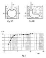
- FIGS. 2A to 2D example different geometries for the hollow body 6 can be seen.
- FIG. 2A is provided a cylindrical geometry of a hollow body 6A with open end faces.
- FIG. 2B is also a cylindrical hollow body 6B is provided, which is closed at its one end face.
- spherical hollow bodies 6C FIG. 2C
- L-shaped hollow body 6D FIG. 2D
- the solids fractions F, G in the suspension 4 have a particle size distribution, as exemplified by the diagram according to FIG. 3 can be seen.
- the particle size x in ⁇ m is plotted against the cumulative solids content a in%. It can be seen that the particle size x ranges from about 0.2 .mu.m to 20 .mu.m, wherein the proportion a of the fine solid fractions F, which have a diameter of less than 1 .mu.m, is more than 95%.
- the proportion of coarse solids G having a particle diameter of more than 5 microns in the range of only a few percentage points based on the total solids content in the suspension 4.
- Based on the suspension 4 is a proportion of 1-15 vol.% Of coarse solids G sought.
- the particle size distribution is chosen such that the largest particles of the coarse solids content have a diameter which corresponds to the maximum pore size of the hollow body 6.
- the coarse solids G With the coarse solids G thereby the pores of the hollow body 6 are added so that the fine solid fractions F do not pass through the wall of the hollow body 20 therethrough. Instead, they deposit on the outside of the hollow body 6 and form a homogeneous and uniform solid layer 32.
- the fine solid fraction F are chosen to be very small and are in particular in a range of about 30% of the size of the small pores. their For example, diameter is typically between 1 and 10 microns.
Landscapes
- Chemical Kinetics & Catalysis (AREA)
- Manufacturing & Machinery (AREA)
- General Chemical & Material Sciences (AREA)
- Engineering & Computer Science (AREA)
- Electrochemistry (AREA)
- Chemical & Material Sciences (AREA)
- Sustainable Development (AREA)
- Sustainable Energy (AREA)
- Life Sciences & Earth Sciences (AREA)
- Fuel Cell (AREA)
- Inert Electrodes (AREA)
- Application Of Or Painting With Fluid Materials (AREA)
- Secondary Cells (AREA)
Description
- Die Erfindung betrifft ein Verfahren zum Aufbringen einer Festelektrolytschicht auf eine poröse Elektrode, insbesondere auf eine Elektrode für eine festkeramische Brennstoffzelle, bei dem auf die Elektrode eine Feststoffschicht aus Festelektrolytmaterial durch Abscheiden von Feststoffanteilen aus einer Suspension aufgebracht wird.
- Eine Brennstoffzelle umfasst regelmäßig eine Anode und eine Kathode, zwischen denen eine Elektrolytschicht aufgebracht ist. Über die Anodenoberfläche wird ein Brennstoff und über die Kathodenoberfläche wird Sauerstoff geleitet. Über die Elektrolytschicht findet ein Ionenaustausch zwischen dem Brennstoff und dem Sauerstoff statt, so dass sich zwischen Anode und Kathode eine Spannung ausbildet.
- Entscheidend für die Effizienz einer Brennstoffzelle ist u.a. die Elektrolytschicht, welche einerseits gut leitfähig für die Ionen sein muss und andererseits weitgehend gasundurchlässig sein sollte, um einen Gasaustausch zwischen Brennstoff und Sauerstoff zu verhindern. An die Elektrolytschicht werden daher hohe Anforderungen gestellt.
- Bei sogenannten festkeramischen Brennstoffzellen (SOFC: Solid Oxide Fuel Cell) ist die Anode sowie die Kathode aus einem porösen keramischen Material gebildet, zwischen denen eine Festelektrolytschicht angeordnet ist. Es sind festkeramische Brennstoffzellen mit einer planaren Geometrie bekannt, bei der die Anode und die Kathode im Wesentlichen planparallel zueinander verlaufen. Daneben ist auch eine zylindrische oder röhrenförmige Ausgestaltung bekannt, bei der die Anode die zylindrisch ausgebildete Kathode unter Einschluss der Festelektrolytschicht umschließt. Zum Aufbringen der Festelektrolytschicht sind eine Vielzahl von Verfahren bekannt. Aus der
DE 196 09 418 C2 ist beispielsweise zu entnehmen, auf eine plane Elektrode eine Suspension aufzubringen, die Feststoffanteile aus dem Festelektrolytmaterial enthält. Überschüssiges Lösungsmittel wird durch Erzeugen eines Unterdrucks auf der der Suspension gegenüberliegenden Seite der porösen Elektrode abgeführt. Die Suspension weist hierbei grobe und feine Feststoffanteile auf, wobei die groben Feststoffanteile zunächst die Poren der Elektrode zusetzen und für eine gute Anbindung zwischen der Elektrolytschicht und der Elektrode sorgen. Die feinen Anteile scheiden sich anschließend auf den groben Anteilen ab. Die Feststoffschicht wird getrocknet und anschließend zur Ausbildung der Festelektrolytschicht gesintert. Dieses Beschichtungsverfahren ist für nicht-plane Flächen kaum geeignet, da das geichmäßige Aufbringen der Suspension auf komplexen Oberflächengeometrien schwierig ist. - Aus der
DE 196 09 418 C2 ist zudem zu entnehmen, dass es bekannt ist, die Elektrolytschicht mittels Elektrophorese oder mittels Foliengießen herzustellen. - Aus dem Aufsatz "Status of Solide Oxide Fuel Cell Technologie" von S.C. Singhal, entnommen aus: High Temperature Electrochemistry: Ceramics and Metals, 17th Risφ International Symposium und Material Sience, Roskilde, Denmark, September 1996, ist zum Aufbringen der Elektrolytschicht ein EVD-Prozess bekannt (EVD: Electrochemical Vapor Deposition). Dieses Verfahren eignet sich auch für komplexe Oberflächengeometrien, insbesondere für die gekrümmten Oberflächen, wie sie bei den Zylinder- oder rohrförmigen Brennstoffzellen vorliegen. Der EVD-Prozess ist jedoch sehr teuer und aufwendig.
- Aus diesem Dokument ist der prinzipielle Aufbau einer röhrenförmigen Brennstoffzelle zu entnehmen. Diese umfasst als Kathode einen porösen keramischen Innenzylinder, auf dem die Elektrolytschicht und anschließend die Anode als Mantel aufgebracht ist. Zur elektrischen Verbindung von zwei Brennstoffzellen in Serie wird die Anode der einen Brennstoffzelle direkt mit einem sogenannten Interkonnektor der zweiten Brennstoffzelle verbunden, wobei die Elektrolytschicht und die Anode der Brennstoffzellen im Bereich des Interkonnektors unterbrochen sind. Aus dem genannten Aufsatz ist zu entnehmen, dass sowohl die Elektrolytschicht als auch der Interkonnektor und die Anode üblicherweise mittels des EVD-Prozesses aufgebracht werden. Der Aufsatz befasst sich mit dem Problem, den teueren EVD-Prozess durch andere Beschichtungssysteme zu ersetzen. Während heute, wie im Aufsatz vorgeschlagen, neue Beschichtungsverfahren für den Interkonnektor und für die Anode entwickelt und auch eingesetzt werden, ist für die Elektrolytschicht weiterhin der EVD-Prozess vorgesehen, um eine ausreichend hohe Qualität zu gewährleisten.
- Der Erfindung liegt die Aufgabe zugrunde, ein einfaches Verfahren zum Aufbringen einer Festelektrolytschicht auf eine poröse Elektrode anzugeben, welches auch für komplexe Geometrien geeignet ist.
- Die Aufgabe wird gemäß der Erfindung gelöst, indem bei dem Verfahren auf die poröse Elektrode, insbesondere auf die Elektrode für eine festkeramische Brennstoffzelle, eine Feststoffschicht aus Festelektrolytmaterial durch Abscheiden von Feststoffanteilen aus einer Suspension aufgebracht wird, wobei die Elektrode als Hohlkörper ausgebildet ist, welcher zur Aufbringung der Feststoffschicht in die Suspension eingetaucht wird.
- Durch das Eintauchen wird in einfacher und vorteilhafter Weise eine gleichmäßige Benetzung der zu beschichtenden Außenfläche des Hohlkörpers erreicht. Durch das Eintauchen können somit auf einfache Art und Weise auch komplexe Bauteilgeometrien beschichtet werden.
- Um ein möglichst rasches Aufbauen der Feststoffschicht zu erzielen, wird zwischen dem Innenraum des Hohlkörpers und der Suspension ein Druckgefälle eingestellt, so dass ein in der Suspension enthaltenes Lösungsmittel in den Innenraum gelangt.
- Ein wesentlicher Vorteil des Eintauchens in die Suspension insbesondere in Verbindung mit dem Anlegen eines Unterdrucks besteht darin, dass unabhängig von der speziellen komplexen Geometrie des Hohlkörpers die Feststoffanteile gleichmäßig auf der Außenfläche abgeschieden werden, so dass am Ende eine dünne, homogene Festelektrolytschicht gleichbleibender Dicke ausgebildet werden kann.
- Vorzugsweise wird das Druckgefälle über eine in den Innenraum reichende Saugleitung aufrecht erhalten, um ein gleichmäßiges Abscheiden der Feststoffanteile zu gewährleisten. Das Druckgefälle oder der Druckunterschied zwischen der suspensionsseitigen Außenseite des Hohlkörpers und der zum Innenraum gewandten Innenseite ist daher während des gesamten Abscheideprozesses möglichst konstant gehalten.
- In einer bevorzugten Ausführung wird das in den Innenraum gelangte Lösungsmittel abgeführt. Dies erlaubt in vergleichsweise einfacher Weise die Aufrechterhaltung eines konstanten Druckgefälles und ist günstig für einen möglichst gleichmäßigen Abscheidungsprozess der Feststoffanteile.
- In besonders zweckdienlicher Weise wird über die Saugleitung zugleich auch das Lösungsmittel abgeführt, so dass ein separates Leitungssystem für das Lösungsmittel nicht erforderlich ist.
- Für einen möglichst einfachen Beschichtungsprozess ist vorteilhafterweise vorgesehen, dass bei Erreichen einer gewünschten Schichtdicke der Feststoffschicht der Hohlkörper aus der Suspension entnommen wird. Die Suspension liegt also im Überschuss vor und es ist nicht notwendig, die Menge der Suspension, in die der Hohlkörper getaucht wird, auf die gewünschte Schichtdicke abzustimmen.
- Um beim Herausnehmen des Hohlkörpers aus der Suspension eine Schädigung der bereits abgeschiedenen Feststoffschicht zu verhindern, wird das Druckgefälle bei der Entnahme des Hohlkörpers vorzugsweise aufrecht erhalten.
- Besonders zweckdienlich ist es, wenn zur Ermittlung der Schichtdicke der bereits abgeschiedenen Feststoffschicht die abgeführte Menge an Lösungsmittel herangezogen wird. Aus der Menge des abgeführten Lösungsmittels ist die Menge der abgeschiedenen Feststoffteile ableitbar. Dies erlaubt ein einfaches Bestimmen der Schichtdicke. Zusätzlich oder alternativ wird die Schichtdicke aus der Menge an eingesaugter Suspension bestimmt. Dies geschieht am einfachsten durch Messung oder Regulierung des Füllstands der Suspension in einem Behälter, in dem die Elektrode eingetaucht ist.
- In einer zweckdienlichen Ausbildung weist die Suspension grobe und feine Feststoffanteile auf, so dass sich eine hochwertige Festelektrolytschicht ausbilden kann. Die groben Feststoffanteile setzen sich in die Poren des Hohlkörpers ab und sorgen damit für eine gute Anbindung der Elektrolytschicht. Die feinen Feststoffanteile scheiden sich anschließend ab und gewährleisten eine weitgehend dichte Ausbildung der Elektrolytschicht.
- Um eine hochwertige Elektrolytschicht zu erreichen, ist vorzugsweise vorgesehen, dass der maximale Durchmesser der groben Feststoffanteile etwa dem maximalen Porendurchmesser des Hohlkörpers entspricht. Typischerweise liegen die Werte für diesen maximalen Durchmesser der groben Feststoffanteile zwischen 5 und 20 µm. Mit einer derartigen Wahl des Durchmessers wird verhindert, dass evtl. zu große grobe Feststoffanteile zu Unebenheiten auf der Oberfläche und damit zu nachteiligen Inhomogenitäten führen. Gleichzeitig wird damit eine gute Ausbildung der Elektrolytschicht auf der Elektrode erreicht.
- Vorzugsweise liegt dabei der Anteil der groben Feststoffanteile etwa zwischen 1 und 15 Vol% der Suspension. Dieser Anteil ist ausreichend, um die oberflächennahen, groben Poren des Hohlkörpers zuzusetzen.
- Um eine möglichst dichte und homogene Elektrolytschicht auszubilden, entspricht der Durchmesser der feinen Feststoffanteile etwa 1/3 des minimalen Porendurchmessers des Hohlkörpers. Vorzugsweise ist der Durchmesser dabei etwa kleiner als 1 µm, da der Porendurchmesser der kleineren Poren etwa zwischen 1 und 10 µm liegt.
- Um die Festigkeit der aufgebrachten Schicht in getrockneter Form zu gewährleisten, wird bevorzugt ein Binder (z.B. Polyethylenimin PEI) der Suspension (4) zugesetzt. Dieses bewirkt ein Verkleben der "grünen" Schichtpartikel.
- Zur gasdichten haftfesten Aufbringung der Festelektrolytschicht wird die Feststoffschicht anschließend vorzugsweise getrocknet und durch Sintern verdichtet. Die entstehende Schicht ist dabei weitgehend gasdicht. Das Sintern erfolgt beispielsweise nach herkömmlicher Art in einem mit Heizstäben beheizten Sinterofen bei Temperaturen von 1300°C bis 1500°C über einen Zeitraum von mehreren Stunden.
- Ein Ausführungsbeispiel der Erfindung wird im Folgenden anhand der Zeichnung näher erläutert. Es zeigen jeweils in schematischen Darstellungen,
- FIG 1
- einen Aufbau zur Durchführung des Verfahrens,
- FIG 2
- beispielhafte Hohlkörper-Geometrien und
- FIG 3
- ein Diagramm zur Teilchengrößenverteilung der Feststoffanteile in einer Suspension
- Gemäß
FIG 1 weist eine Anordnung zur Durchführung des Verfahrens einen Behälter 2 auf, in dem eine Suspension 4 eingefüllt ist. Die Suspension 4 umfasst ein Lösungsmittel L, feine Feststoffanteile F und grobe Feststoffanteile G sowie einen Binder B. Die Feststoffanteile F,G bestehen aus einem Festelektrolytmaterial und sind in der Suspension 4 homogen verteilt. In diese Suspension 4 ist ein zylindrischer Hohlkörper 6 eingetaucht, der als Elektrode, insbesondere Kathode, für eine röhrenförmige Brennstoffzelle dient. Der Hohlkörper 6 besteht aus einer porösen Keramik. Seine offenen Stirnseiten sind über jeweils einen Verschlussstopfen 8A,8B abgedichtet, damit die Suspension 4 nicht in den Innenraum 10 des Hohlkörpers 6 gelangt. Durch den oberen Verschlussstopfen 8A ist eine Saugleitung 12 in den Innenraum 10 geführt und erstreckt sich innerhalb dessen bis in etwa zu dem gegenüberliegenden Verschlussstopfen 8B. Die Saugleitung 12 ist mit einer Pumpeinrichtung 14 verbunden, und an ihr ist ein Durchflussmessgerät 16 angeordnet. Dieses ist mit einer Steuereinrichtung 18 verbunden, über die die Pumpeinrichtung 14 ansteuerbar ist. Die Pumpeinrichtung 14 dient zur Erzeugung eines Druckgefälles über die Wand 20 des Hohlkörpers 6. Zwischen der der Suspension 4 zugewandten Außenseite und der zum Innenraum 10 hin orientierten Innenseite des Hohlkörpers 6 wird also eine Druckdifferenz aufgebaut. - Die Pumpeinrichtung 14 ist zum Trennen von gasförmigen Anteilen von flüssigen Anteilen ausgelegt. Sie weist hierzu eine in einen Auffangbehälter 28 mündende Ableitung 26 sowie eine Abgasleitung 30 auf.
- An der Außenseite des eingetauchten Hohlkörpers 6 scheiden sich die Feststoffanteile F,G,B ab und bilden eine Feststoffschicht 32 aus Festelektrolytmaterial. Durch die Erzeugung der Druckdifferenz über die Pumpeinrichtung 14 wird für einen kontinuierlichen und dauerhaften Schichtaufbau gesorgt. Aufgrund der porösen Ausbildung des Hohlkörpers 6 gelangt das Lösungsmittel L durch den Hohlkörper 6 hindurch in den Innenraum 10. Aus diesem wird das Lösungsmittel über die Saugleitung 12 insbesondere kontinuierlich abgepumpt. Die Saugleitung 12 dient daher gleichzeitig zum Abpumpen von Gas aus dem Innenraum 10 und zum Abpumpen von Lösungsmittel L zur Erzeugung und Aufrechterhaltung des Druckgefälles. Das abgepumpte Lösungsmittel L wird im Auffangbehälter 28 gesammelt. Die Menge des abgepumpten Lösungsmittels L wird über das Durchflussmessgerät 16 gemessen. Aus der gemessenen Menge wird unter Berücksichtigung des Feststoffanteils in der Suspension 4 mittels der Steuereinrichtung 18 die Schichtdicke der abgeschiedenen Feststoffschicht 32 berechnet. Ist der Feststoffgehalt der Suspension (4) bekannt, so kann die Schichtdickeneinstellung über die Regulierung des Niveaus 34, der Suspension 4 im Behälter 2, beispielsweise mit Hilfe einer Skala 36, vorgenommen werden.
- Sobald die gewünschte Schichtdicke erreicht ist, wird der Hohlkörper 6 unter Beibehaltung der Druckdifferenz aus der Suspension 4 entnommen oder die Suspension abgelassen. Der Hohlkörper 6 weist nunmehr eine homogen aufgebrachte Feststoffschicht 32 aus Festelektrolytmaterial auf. Zur Vollendung der Festelektrolytschicht wird in weiteren Verfahrensschritten die Feststoffschicht 32 zunächst vorzugsweise an der Luft getrocknet und anschließend durch Sintern verdichtet. Das Sintern erfolgt beispielsweise durch ein herkömmliches Sinterverfahren bei hohen Temperaturen von 1300°C bis 1500°C und bei einer Sinterzeit von mehreren Stunden.
- Das beschriebene Verfahren dient zum Aufbringen einer Festelektrolytschicht auf der Anode einer Brennstoffzelle mit insbesondere tubularem oder röhrenförmigem Aufbau. Durch das Eintauchen in die Suspension 4 ist in einfacher Weise eine homogene und gleichmäßige Beschichtung des Hohlkörpers 6 ermöglicht. Insbesondere lassen sich damit auch komplexe Körpergeometrien in einfacher Weise homogen beschichten.
- Aus den
FIG 2A bis 2D sind beispielhaft unterschiedliche Geometrien für den Hohlkörper 6 zu entnehmen. GemäßFIG 2A ist eine zylindrische Geometrie eines Hohlkörpers 6A mit offenen Stirnseiten vorgesehen. GemäßFIG 2B ist ein ebenfalls zylindrischer Hohlkörper 6B vorgesehen, welcher an seiner einen Stirnseite verschlossen ist. Ebenso lassen sich kugelförmige Hohlkörper 6C (FIG 2C ) oder andersartig geformte, beispielsweise L-förmige Hohlkörper 6D (FIG 2D ) mit diesem Verfahren homogen beschichten. - Die Feststoffanteile F,G in der Suspension 4 weisen eine Teilchengrößenverteilung auf, wie sie beispielhaft dem Diagramm gemäß
FIG 3 zu entnehmen ist. In dem Diagramm ist die Teilchengröße x in µm gegenüber dem kumulierten Feststoffanteil a in % aufgetragen. Hieraus ist zu entnehmen, dass die Teilchengröße x von etwa 0,2 µm bis 20 µm reicht, wobei der Anteil a der feinen Feststoffanteile F, die einen Durchmesser < 1 µm aufweisen über 95% liegt. Dementsprechend liegt der Anteil der groben Feststoffanteile G mit einem Teilchendurchmesser über 5 µm im Bereich von nur wenigen Prozentpunkten, bezogen auf den gesamten Feststoffanteil in der Suspension 4. Bezogen auf die Suspension 4 wird ein Anteil von 1-15 Vol.% der groben Feststoffanteile G angestrebt. - Die Teilchengrößenverteilung ist derart gewählt, dass die größten Teilchen des groben Feststoffanteils einen Durchmesser aufweisen, welcher der maximalen Porengröße des Hohlkörpers 6 entspricht. Mit den groben Feststoffanteilen G werden dadurch die Poren des Hohlkörpers 6 zugesetzt, so dass die feinen Feststoffanteile F nicht durch die Wand des Hohlkörpers 20 hindurch gelangen. Sie lagern sich vielmehr auf der Außenseite des Hohlkörpers 6 ab und bilden eine homogene und gleichmäßige Feststoffschicht 32 aus. Um eine möglichst dichte Feststoffschicht und damit auch eine möglichst dichte Festelektrolytschicht zu erhalten, sind die feinen Feststoffanteil F sehr klein gewählt und liegen insbesondere in einem Bereich von etwa 30% der Größe der kleinen Poren. Deren Durchmesser liegt beispielsweise typischerweise zwischen 1 und 10 µm.
Claims (13)
- Verfahren zum Aufbringen einer Festelektrolytschicht auf eine poröse Elektrode (6) für eine festkeramische Brennstoffzelle, bei dem auf die Elektrode eine Feststoffschicht (32) aus Festelektrolytmaterial durch Abscheiden von Feststoffanteilen (F, G) aus einer Suspension (4) aufgebracht wird, dadurch gekennzeichnet,- dass die Elektrode (6) als Hohlkörper ausgebildet ist, welcher zur Aufbringung der Feststoffschicht (32) in die Suspension (4) eingetaucht wird und- dass ein Druckgefälle zwischen dem Innenraum (10) des Hohlkörpers (6) und der Suspension (4) eingestellt wird, so dass ein in der Suspension enthaltenes Lösungsmittel (1) in den Innenraum (10) des Hohlkörpers (6) gelangt, und die Feststoffanteile (F, G) außen am Hohlkörper (6) abgeschieden werden.
- Verfahren nach Anspruch 1,
dadurch gekennzeichnet,
dass das Druckgefälle über eine in den Innenraum (10) reichende Saugleitung (12) aufrecht erhalten wird. - Verfahren nach Anspruch 1 bis 2,
dadurch gekennzeichnet,
dass das durch den Hohlkörper (6) gelangtes Lösungsmittel (2) abgeführt wird. - Verfahren nach Anspruch 1 bis 3,
dadurch gekennzeichnet,
dass über die Saugleitung (12) das Lösungsmittel (2) abgeführt wird. - Verfahren nach einem der Ansprüche 1 bis 4,
dadurch gekennzeichnet,
dass bei Erreichen einer gewünschten Schichtdicke der Feststoffschicht (32) der Hohlkörper (6) aus der Suspension (4) entnommen wird. - Verfahren nach Anspruch 1 bis 5,
dadurch gekennzeichnet,
dass das Druckgefälle bei der Entnahme des Hohlkörpers (6) aus der Suspension (4) aufrechterhalten wird. - Verfahren nach einem der Ansprüche 1 bis 6,
dadurch gekennzeichnet,
dass die Schichtdicke durch Messung der abgeführten Menge an Lösungsmittel (1) und/oder durch Messung der Menge an eingesaugter Suspension (4) ermittelt wird. - Verfahren nach einem der Ansprüche 1 bis 7,
dadurch gekennzeichnet,
dass die Suspension (4) grobe Feststoffanteile (G) und feine Feststoffanteile (F) aufweist. - Verfahren nach Anspruch 8,
dadurch gekennzeichnet,
dass der maximale Durchmesser der groben Feststoffanteile (G) etwa dem maximalen Porendurchmesser des Hohlkörpers (6) entspricht und insbesondere etwa zwischen 5 und 20 µm liegt. - Verfahren nach Anspruch 8 bis 9,
dadurch gekennzeichnet,
dass der Anteil der groben Feststoffanteile (G) etwa 1 bis 15 Vol.-% der Suspension (4) beträgt. - Verfahren nach einem der Ansprüche 8 bis 10,
dadurch gekennzeichnet,
dass der Durchmesser der feinen Feststoffanteile (F) etwa 1/3 des minimalen Porendurchmessers des Hohlkörpers (6) entspricht und insbesondere etwa kleiner als 1 µm ist. - Verfahren nach einem der Ansprüche 1 bis 11,
dadurch gekennzeichnet,
dass die Suspension einen Binder (B) aufweist. - Verfahren nach einem der Ansprüche 1 bis 12,
dadurch gekennzeichnet,
dass die abgeschiedene Feststoffschicht (32) getrocknet und anschließend durch Sintern zur Festelektrolytschicht verdichtet wird.
Priority Applications (2)
| Application Number | Priority Date | Filing Date | Title |
|---|---|---|---|
| EP01943466.1A EP1287576B1 (de) | 2000-06-09 | 2001-06-01 | Verfahren zum aufbringen einer festelektrolytschicht auf eine poröse elektrode |
| CY20161100227T CY1117289T1 (el) | 2000-06-09 | 2016-03-17 | Μεθοδος για την εφαρμογη μιας στερεης ηλεκτρολυτικης στρωσης σε ενα πορωδες ηλεκτροδιο |
Applications Claiming Priority (4)
| Application Number | Priority Date | Filing Date | Title |
|---|---|---|---|
| EP00112393 | 2000-06-09 | ||
| EP00112393 | 2000-06-09 | ||
| EP01943466.1A EP1287576B1 (de) | 2000-06-09 | 2001-06-01 | Verfahren zum aufbringen einer festelektrolytschicht auf eine poröse elektrode |
| PCT/EP2001/006251 WO2001095420A1 (de) | 2000-06-09 | 2001-06-01 | Verfahren zum aufbringen einer festelektrolytschicht auf eine poröse elektrode |
Publications (2)
| Publication Number | Publication Date |
|---|---|
| EP1287576A1 EP1287576A1 (de) | 2003-03-05 |
| EP1287576B1 true EP1287576B1 (de) | 2015-12-23 |
Family
ID=8168949
Family Applications (1)
| Application Number | Title | Priority Date | Filing Date |
|---|---|---|---|
| EP01943466.1A Expired - Lifetime EP1287576B1 (de) | 2000-06-09 | 2001-06-01 | Verfahren zum aufbringen einer festelektrolytschicht auf eine poröse elektrode |
Country Status (9)
| Country | Link |
|---|---|
| EP (1) | EP1287576B1 (de) |
| AU (2) | AU2001266040B2 (de) |
| CA (1) | CA2411711C (de) |
| CY (1) | CY1117289T1 (de) |
| DK (1) | DK1287576T3 (de) |
| ES (1) | ES2557739T3 (de) |
| NO (1) | NO328244B1 (de) |
| PT (1) | PT1287576E (de) |
| WO (1) | WO2001095420A1 (de) |
Family Cites Families (3)
| Publication number | Priority date | Publication date | Assignee | Title |
|---|---|---|---|---|
| NL9002168A (nl) * | 1990-10-05 | 1992-05-06 | Blandikus Catharikus Jaspers E | Holle elektrode voor een elektrochemische cel voorzien van ten minste een toe- en een afvoeropening voor gassen, alsmede elektrochemische cel die een dergelijke elektrode omvat. |
| DE19609418C2 (de) * | 1996-03-11 | 1998-08-13 | Forschungszentrum Juelich Gmbh | Beschichtung von porösen Elektroden mit dünnen Elektrolytschichten |
| DE19628593A1 (de) * | 1996-07-16 | 1998-01-22 | Hans Hoffmann | Elektrodenanordnung, daraus hergestellte Brennstoffzelle und Verfahren zu deren Herstellung |
-
2001
- 2001-06-01 AU AU2001266040A patent/AU2001266040B2/en not_active Ceased
- 2001-06-01 DK DK01943466.1T patent/DK1287576T3/en active
- 2001-06-01 AU AU6604001A patent/AU6604001A/xx active Pending
- 2001-06-01 CA CA2411711A patent/CA2411711C/en not_active Expired - Fee Related
- 2001-06-01 WO PCT/EP2001/006251 patent/WO2001095420A1/de not_active Ceased
- 2001-06-01 PT PT1943466T patent/PT1287576E/pt unknown
- 2001-06-01 EP EP01943466.1A patent/EP1287576B1/de not_active Expired - Lifetime
- 2001-06-01 ES ES01943466.1T patent/ES2557739T3/es not_active Expired - Lifetime
-
2002
- 2002-12-04 NO NO20025826A patent/NO328244B1/no not_active IP Right Cessation
-
2016
- 2016-03-17 CY CY20161100227T patent/CY1117289T1/el unknown
Also Published As
| Publication number | Publication date |
|---|---|
| CA2411711C (en) | 2010-11-30 |
| PT1287576E (pt) | 2016-03-03 |
| EP1287576A1 (de) | 2003-03-05 |
| WO2001095420A1 (de) | 2001-12-13 |
| NO20025826D0 (no) | 2002-12-04 |
| AU6604001A (en) | 2001-12-17 |
| NO20025826L (no) | 2003-02-06 |
| NO328244B1 (no) | 2010-01-18 |
| DK1287576T3 (en) | 2016-01-25 |
| CA2411711A1 (en) | 2001-12-13 |
| ES2557739T3 (es) | 2016-01-28 |
| CY1117289T1 (el) | 2017-04-26 |
| AU2001266040B2 (en) | 2006-03-16 |
Similar Documents
| Publication | Publication Date | Title |
|---|---|---|
| DE60222448T2 (de) | Verfahren zur herstellung gesinterter poröser körper | |
| DE69217039T2 (de) | Laminiertes filtermedium, methode zur herstellung des mediums und filter, der das medium verwendet | |
| DE112010001642T5 (de) | Material auf titanbasis, verfahren zum herstellen eines materials auf titanbasis und brenstoffzellenseparator | |
| EP1587969B1 (de) | Verfahren zum herstellen von metallischen formkörpern mit einer keramischen schicht, metallischer formkörper und dessen verwendung | |
| Harbach et al. | Homogeneous functional ceramic components through electrophoretic deposition from stable colloidal suspensions—I. Basic concepts and application to zirconia | |
| DE102014109321A1 (de) | Verfahren zur Herstellung einer Bipolarplatte, Bipolarplatte für eine elektrochemische Zelle und elektrochemische Zelle | |
| EP1246288B1 (de) | Poröser, gasdurchlässiger Schichtunterbau zu einer dünnen, gasdichten Schicht, zur Verwendung als funktionelle Komponente in Hochtemperatur-Brennstoffzellen | |
| DE60123839T2 (de) | Gestapelte mikrostrukturen leitender, keramischer oxidionenmembranen; verwendung zur trennung von sauerstoff von luft | |
| WO2010037755A1 (de) | Verfahren zur herstellung eines interkonnektors für hochtemperatur-brennstoffzellen, zugehörige hochtemperatur-brennstoffzelle sowie damit aufgebaute brennstoffzellenanlage | |
| DE2359505C1 (de) | Verfahren und Vorrichtung zur Herstellung eines rohrförmigen Filterelements | |
| EP1344272A2 (de) | Verfahren zum herstellen einer festkeramischen brennstoffzelle | |
| DE19609418C2 (de) | Beschichtung von porösen Elektroden mit dünnen Elektrolytschichten | |
| DE3019902C2 (de) | Verfahren zur Herstllung eines Sauerstoffsensors mit gesinterter Festelektrolytschicht | |
| DE3238824A1 (de) | Sauerstoffmessfuehlerelement und verfahren zu dessen herstellung | |
| EP3042413A1 (de) | Pulvermetallurgisches formteil als interkonnektor oder endplatte für eine elektrochemische zelle | |
| DE2313104C3 (de) | Verfahren zum Aufbringen einer festhaftenden Schicht nichtmetallischer Stoffe auf einer elektrisch leitenden Unterlage | |
| DE102007026233A1 (de) | Verfahren zur Herstellung einer gasdichten Festelektrolytschicht und Festelektrolytschicht | |
| DE10212966B4 (de) | Hochtemperatur-Brennstoffzelle und Verfahren zu deren Herstellung | |
| EP0745702B1 (de) | Vorrichtung zur elektrophoretischen Beschichtung von Substraten | |
| DE10313847B4 (de) | Verfahren zur Herstellung keramischer Formkörper mit sprunghaftem Strukturgradienten und keramischer Formkörper mit sprunghaftem Strukturgradienten | |
| RU2048974C1 (ru) | Способ изготовления спеченных пористых изделий | |
| WO2001095420A1 (de) | Verfahren zum aufbringen einer festelektrolytschicht auf eine poröse elektrode | |
| DE19801440C2 (de) | Kostengünstiges Verfahren zur Herstellung einer Elektroden-Elektrolyt-Einheit | |
| EP0311804A1 (de) | Verfahren zur Herstellung supraleitender keramischer Schichten | |
| DE19524750A1 (de) | Verfahren zur elektrophoretischen Beschichtung eines Trägersubstrats |
Legal Events
| Date | Code | Title | Description |
|---|---|---|---|
| PUAI | Public reference made under article 153(3) epc to a published international application that has entered the european phase |
Free format text: ORIGINAL CODE: 0009012 |
|
| AK | Designated contracting states |
Kind code of ref document: A1 Designated state(s): AT BE CH CY DE DK ES FI FR GB GR IE IT LI LU MC NL PT SE TR |
|
| AX | Request for extension of the european patent |
Extension state: AL LT LV MK RO SI |
|
| 17P | Request for examination filed |
Effective date: 20021216 |
|
| RIN1 | Information on inventor provided before grant (corrected) |
Inventor name: FLECK, ROBERT Inventor name: JANSING, THOMAS Inventor name: BLASS, GUENTER Inventor name: BUCHKREMER, HANS, PETER Inventor name: FLESCH, UDO |
|
| 17Q | First examination report despatched |
Effective date: 20090202 |
|
| GRAP | Despatch of communication of intention to grant a patent |
Free format text: ORIGINAL CODE: EPIDOSNIGR1 |
|
| GRAS | Grant fee paid |
Free format text: ORIGINAL CODE: EPIDOSNIGR3 |
|
| INTG | Intention to grant announced |
Effective date: 20150916 |
|
| RIN1 | Information on inventor provided before grant (corrected) |
Inventor name: FLECK, ROBERT Inventor name: JANSING, THOMAS Inventor name: BLASS, GUENTER Inventor name: FLESCH, UDO Inventor name: BUCHKREMER, HANS, PETER |
|
| GRAA | (expected) grant |
Free format text: ORIGINAL CODE: 0009210 |
|
| AK | Designated contracting states |
Kind code of ref document: B1 Designated state(s): AT BE CH CY DE DK ES FI FR GB GR IE IT LI LU MC NL PT SE TR |
|
| REG | Reference to a national code |
Ref country code: GB Ref legal event code: FG4D Free format text: NOT ENGLISH |
|
| REG | Reference to a national code |
Ref country code: CH Ref legal event code: EP |
|
| REG | Reference to a national code |
Ref country code: IE Ref legal event code: FG4D Free format text: LANGUAGE OF EP DOCUMENT: GERMAN |
|
| REG | Reference to a national code |
Ref country code: AT Ref legal event code: REF Ref document number: 766892 Country of ref document: AT Kind code of ref document: T Effective date: 20160115 |
|
| REG | Reference to a national code |
Ref country code: DK Ref legal event code: T3 Effective date: 20160118 |
|
| REG | Reference to a national code |
Ref country code: ES Ref legal event code: FG2A Ref document number: 2557739 Country of ref document: ES Kind code of ref document: T3 Effective date: 20160128 |
|
| REG | Reference to a national code |
Ref country code: DE Ref legal event code: R096 Ref document number: 50116520 Country of ref document: DE |
|
| REG | Reference to a national code |
Ref country code: PT Ref legal event code: SC4A Free format text: AVAILABILITY OF NATIONAL TRANSLATION Effective date: 20160126 |
|
| REG | Reference to a national code |
Ref country code: SE Ref legal event code: TRGR |
|
| RIN2 | Information on inventor provided after grant (corrected) |
Inventor name: FLESCH, UDO Inventor name: JANSING, THOMAS Inventor name: BLASS, GUENTER Inventor name: FLECK, ROBERT Inventor name: BUCHKREMER, HANS, PETER |
|
| REG | Reference to a national code |
Ref country code: NL Ref legal event code: FP |
|
| REG | Reference to a national code |
Ref country code: GR Ref legal event code: EP Ref document number: 20160400151 Country of ref document: GR Effective date: 20160414 |
|
| REG | Reference to a national code |
Ref country code: FR Ref legal event code: PLFP Year of fee payment: 16 |
|
| REG | Reference to a national code |
Ref country code: DE Ref legal event code: R097 Ref document number: 50116520 Country of ref document: DE |
|
| PLBE | No opposition filed within time limit |
Free format text: ORIGINAL CODE: 0009261 |
|
| STAA | Information on the status of an ep patent application or granted ep patent |
Free format text: STATUS: NO OPPOSITION FILED WITHIN TIME LIMIT |
|
| 26N | No opposition filed |
Effective date: 20160926 |
|
| REG | Reference to a national code |
Ref country code: FR Ref legal event code: PLFP Year of fee payment: 17 |
|
| PGFP | Annual fee paid to national office [announced via postgrant information from national office to epo] |
Ref country code: DK Payment date: 20170626 Year of fee payment: 17 Ref country code: IE Payment date: 20170622 Year of fee payment: 17 Ref country code: MC Payment date: 20170621 Year of fee payment: 17 |
|
| PGFP | Annual fee paid to national office [announced via postgrant information from national office to epo] |
Ref country code: FI Payment date: 20170620 Year of fee payment: 17 Ref country code: SE Payment date: 20170626 Year of fee payment: 17 Ref country code: NL Payment date: 20170621 Year of fee payment: 17 Ref country code: IT Payment date: 20170622 Year of fee payment: 17 Ref country code: LU Payment date: 20170622 Year of fee payment: 17 Ref country code: PT Payment date: 20170526 Year of fee payment: 17 Ref country code: BE Payment date: 20170621 Year of fee payment: 17 |
|
| PGFP | Annual fee paid to national office [announced via postgrant information from national office to epo] |
Ref country code: TR Payment date: 20170530 Year of fee payment: 17 |
|
| PGFP | Annual fee paid to national office [announced via postgrant information from national office to epo] |
Ref country code: CY Payment date: 20170525 Year of fee payment: 17 Ref country code: ES Payment date: 20170703 Year of fee payment: 17 |
|
| REG | Reference to a national code |
Ref country code: FR Ref legal event code: PLFP Year of fee payment: 18 |
|
| PGFP | Annual fee paid to national office [announced via postgrant information from national office to epo] |
Ref country code: CH Payment date: 20180626 Year of fee payment: 18 Ref country code: DE Payment date: 20180430 Year of fee payment: 18 |
|
| PGFP | Annual fee paid to national office [announced via postgrant information from national office to epo] |
Ref country code: FR Payment date: 20180625 Year of fee payment: 18 Ref country code: AT Payment date: 20180620 Year of fee payment: 18 |
|
| PGFP | Annual fee paid to national office [announced via postgrant information from national office to epo] |
Ref country code: GB Payment date: 20180626 Year of fee payment: 18 |
|
| REG | Reference to a national code |
Ref country code: DK Ref legal event code: EBP Effective date: 20180630 |
|
| REG | Reference to a national code |
Ref country code: SE Ref legal event code: EUG |
|
| PG25 | Lapsed in a contracting state [announced via postgrant information from national office to epo] |
Ref country code: FI Free format text: LAPSE BECAUSE OF NON-PAYMENT OF DUE FEES Effective date: 20180601 Ref country code: CY Free format text: LAPSE BECAUSE OF NON-PAYMENT OF DUE FEES Effective date: 20180601 Ref country code: PT Free format text: LAPSE BECAUSE OF NON-PAYMENT OF DUE FEES Effective date: 20181203 Ref country code: SE Free format text: LAPSE BECAUSE OF NON-PAYMENT OF DUE FEES Effective date: 20180602 |
|
| REG | Reference to a national code |
Ref country code: NL Ref legal event code: MM Effective date: 20180701 |
|
| REG | Reference to a national code |
Ref country code: BE Ref legal event code: MM Effective date: 20180630 |
|
| REG | Reference to a national code |
Ref country code: IE Ref legal event code: MM4A |
|
| PG25 | Lapsed in a contracting state [announced via postgrant information from national office to epo] |
Ref country code: MC Free format text: LAPSE BECAUSE OF NON-PAYMENT OF DUE FEES Effective date: 20180702 Ref country code: LU Free format text: LAPSE BECAUSE OF NON-PAYMENT OF DUE FEES Effective date: 20180601 Ref country code: NL Free format text: LAPSE BECAUSE OF NON-PAYMENT OF DUE FEES Effective date: 20180701 |
|
| PG25 | Lapsed in a contracting state [announced via postgrant information from national office to epo] |
Ref country code: IT Free format text: LAPSE BECAUSE OF NON-PAYMENT OF DUE FEES Effective date: 20180601 Ref country code: IE Free format text: LAPSE BECAUSE OF NON-PAYMENT OF DUE FEES Effective date: 20180601 |
|
| PG25 | Lapsed in a contracting state [announced via postgrant information from national office to epo] |
Ref country code: BE Free format text: LAPSE BECAUSE OF NON-PAYMENT OF DUE FEES Effective date: 20180630 Ref country code: GR Free format text: LAPSE BECAUSE OF NON-PAYMENT OF DUE FEES Effective date: 20190107 |
|
| PG25 | Lapsed in a contracting state [announced via postgrant information from national office to epo] |
Ref country code: DK Free format text: LAPSE BECAUSE OF NON-PAYMENT OF DUE FEES Effective date: 20180630 |
|
| REG | Reference to a national code |
Ref country code: ES Ref legal event code: FD2A Effective date: 20190913 |
|
| PG25 | Lapsed in a contracting state [announced via postgrant information from national office to epo] |
Ref country code: ES Free format text: LAPSE BECAUSE OF NON-PAYMENT OF DUE FEES Effective date: 20180602 |
|
| REG | Reference to a national code |
Ref country code: DE Ref legal event code: R119 Ref document number: 50116520 Country of ref document: DE |
|
| REG | Reference to a national code |
Ref country code: CH Ref legal event code: PL |
|
| REG | Reference to a national code |
Ref country code: AT Ref legal event code: MM01 Ref document number: 766892 Country of ref document: AT Kind code of ref document: T Effective date: 20190601 |
|
| GBPC | Gb: european patent ceased through non-payment of renewal fee |
Effective date: 20190601 |
|
| PG25 | Lapsed in a contracting state [announced via postgrant information from national office to epo] |
Ref country code: GB Free format text: LAPSE BECAUSE OF NON-PAYMENT OF DUE FEES Effective date: 20190601 Ref country code: DE Free format text: LAPSE BECAUSE OF NON-PAYMENT OF DUE FEES Effective date: 20200101 Ref country code: AT Free format text: LAPSE BECAUSE OF NON-PAYMENT OF DUE FEES Effective date: 20190601 |
|
| PG25 | Lapsed in a contracting state [announced via postgrant information from national office to epo] |
Ref country code: LI Free format text: LAPSE BECAUSE OF NON-PAYMENT OF DUE FEES Effective date: 20190630 Ref country code: CH Free format text: LAPSE BECAUSE OF NON-PAYMENT OF DUE FEES Effective date: 20190630 |
|
| PG25 | Lapsed in a contracting state [announced via postgrant information from national office to epo] |
Ref country code: FR Free format text: LAPSE BECAUSE OF NON-PAYMENT OF DUE FEES Effective date: 20190630 |
|
| PG25 | Lapsed in a contracting state [announced via postgrant information from national office to epo] |
Ref country code: TR Free format text: LAPSE BECAUSE OF NON-PAYMENT OF DUE FEES Effective date: 20180601 |