EP1286604B1 - Systeme de filtration d'air comprenant un ensemble casque avec au moins deux sorties d'air pour distribuer l'air autour de la tête d'un utilisateur - Google Patents
Systeme de filtration d'air comprenant un ensemble casque avec au moins deux sorties d'air pour distribuer l'air autour de la tête d'un utilisateur Download PDFInfo
- Publication number
- EP1286604B1 EP1286604B1 EP01908633A EP01908633A EP1286604B1 EP 1286604 B1 EP1286604 B1 EP 1286604B1 EP 01908633 A EP01908633 A EP 01908633A EP 01908633 A EP01908633 A EP 01908633A EP 1286604 B1 EP1286604 B1 EP 1286604B1
- Authority
- EP
- European Patent Office
- Prior art keywords
- air
- assembly
- user
- set forth
- head
- Prior art date
- Legal status (The legal status is an assumption and is not a legal conclusion. Google has not performed a legal analysis and makes no representation as to the accuracy of the status listed.)
- Expired - Lifetime
Links
Images


Classifications
-
- A—HUMAN NECESSITIES
- A42—HEADWEAR
- A42B—HATS; HEAD COVERINGS
- A42B3/00—Helmets; Helmet covers ; Other protective head coverings
- A42B3/04—Parts, details or accessories of helmets
- A42B3/28—Ventilating arrangements
- A42B3/286—Ventilating arrangements with forced flow, e.g. by a fan
-
- A—HUMAN NECESSITIES
- A41—WEARING APPAREL
- A41D—OUTERWEAR; PROTECTIVE GARMENTS; ACCESSORIES
- A41D13/00—Professional, industrial or sporting protective garments, e.g. surgeons' gowns or garments protecting against blows or punches
- A41D13/05—Professional, industrial or sporting protective garments, e.g. surgeons' gowns or garments protecting against blows or punches protecting only a particular body part
- A41D13/11—Protective face masks, e.g. for surgical use, or for use in foul atmospheres
- A41D13/1107—Protective face masks, e.g. for surgical use, or for use in foul atmospheres characterised by their shape
- A41D13/1153—Protective face masks, e.g. for surgical use, or for use in foul atmospheres characterised by their shape with a hood
-
- A—HUMAN NECESSITIES
- A62—LIFE-SAVING; FIRE-FIGHTING
- A62B—DEVICES, APPARATUS OR METHODS FOR LIFE-SAVING
- A62B18/00—Breathing masks or helmets, e.g. affording protection against chemical agents or for use at high altitudes or incorporating a pump or compressor for reducing the inhalation effort
- A62B18/04—Gas helmets
- A62B18/045—Gas helmets with fans for delivering air for breathing mounted in or on the helmet
Definitions
- the subject invention generally relates to an air filtration system for filtering air between a head and body of a user and an environment external to the user.
- the air filtration system is utilized in the medical profession during surgical procedures.
- the subject invention more specifically relates to a helmet assembly and gown for use in the air filtration system.
- Air filtration systems and helmet assemblies utilized in the air filtration systems are known in the art. As indicated above, air filtration systems and helmet assemblies are worn by users throughout the medical profession, such as surgeons, during surgical procedures for filtering air between a head and body of the surgeon and an external environment, such as a clean room.
- United States Patent No. 5,592,936 to Thomas, Jr. et al. discloses an air filtration system and helmet assembly that draws air through a filter medium into the helmet assembly and through an intake grid where the air is then channeled through an air flow channel over a face of the user.
- the air filtration system and helmet assembly of this patent are deficient in that air is not distributed completely about the head of the user. That is, air is not distributed to a back of the head, toward a neck, of the user.
- the intake grid is deficient in that the grid does not extend between a front and rear section of the helmet assembly to maximize an effective intake area for the filter medium.
- a further example of a conventional air filtration system and helmet assembly is disclosed in United States Patent No. 5,054,480 to Bare et al.
- This patent discloses an air filtration system and helmet assembly that draws air into the helmet assembly via an intake fan, and exhausts air from the air filtration system and helmet assembly via an exhaust fan disposed at the rear section of the helmet assembly spaced away from the neck of the user.
- the air filtration system and helmet assembly of this patent is deficient in that they are overly heavy due to the additional fan required to exhaust air.
- the exhaust fan creates excessive strain, and therefore fatigue, in the neck of the user because the exhaust fan is spaced away from the neck of the user.
- the conventional air filtration system and helmet assembly disclosed in United States Patent No. 5,711,033 to Green et al is also deficient.
- This patent discloses an air filtration system and helmet assembly that draws air into the helmet assembly through an intake fan and scroll housing disposed at a rear section of the helmet assembly.
- the air filtration and helmet assembly of this patent is deficient because the intake fan and scroll housing are spaced away from the neck of the user.
- the scroll housing in this patent includes only one air outlet to distribute air about the head of the user resulting in less balanced air flow throughout the helmet assembly. Additional drawbacks of such an air filtration system and helmet assembly including only one air outlet from the scroll housing are excessive fog build-up and poorer heat dissipation in the helmet assembly.
- the prior art air filtration systems and helmet assemblies do not incorporate a strap flexibly connected to the front section of the helmet assembly such that the strap is pulled from the front section of the helmet assembly and the weight of any fans is maintained over the user's neck when the helmet assembly is adjusted to fit various sized heads.
- a novel air filtration system and helmet assembly that utilizes a single fan to distribute air toward both the face and the neck of the user and that includes a scroll housing that includes at least two air outlets for complete balancing of the air flow about the head of the user. It is also desirable to dispose the fan in the helmet assembly such that it is not spaced away from the neck of the user to minimize strain, and to include an intake grid that extends between front and rear sections of the helmet assembly to maximize the effective intake area for filtering the air.
- An air filtration system for filtering air and a helmet assembly for use in the air filtration system is disclosed.
- the air filtration system and helmet assembly are utilized in the medical profession during surgical procedures to filter air between a head and body of a user, such as a surgeon, and an environment external to the user.
- the subject invention in addition to air filtering, assists in controlling carbon dioxide concentration, dissipating heat, and anti-fogging within the helmet assembly. It is to be understood that the subject invention can also be utilized in other situations requiring filtered air including, but not limited to, the manufacturing of semi-conductor chips and other computer components in manufacturing clean rooms.
- the air filtration system and helmet assembly include an inner structural shell and an outer structural shell.
- the outer structural shell extends from the inner structural shell to define at least one air flow channel between the inner and outer shells for channeling air about the head of the user.
- the helmet assembly further includes a base section and a facial section extending from the base section to define a facial opening.
- a fan module is mounted to at least one of the inner and outer shells, and a scroll housing is mounted adjacent the fan module. More specifically, the fan module includes a fan and a motor, and the scroll housing includes at least one air inlet and at least two air outlets. The fan module, including both the fan and the motor, is disposed at the rear section of the base section. In operation, the fan module, specifically the fan, draws air into the air inlet and distributes air out of the scroll housing through the air outlet or outlets and into the air flow channel.
- the subject invention also incorporates at least two helmet air exits, preferably a front and rear air helmet air exit for distributing air from the air flow channel toward the head of the user. More specifically, the front and rear air exits are disposed at the front and rear sections of the helmet assembly, respectively. The front and rear air exits are in fluid communication with the air flow channel and the air outlets. The front air exit distributes air from the air flow channel toward a front, or face, of the head of the user, and the rear air exit distributes air from the air flow channel toward a back, or neck, of the head of the user. As such, a single fan is utilized to distribute air toward both the face and the neck of the user.
- a single fan is utilized to distribute air toward both the face and the neck of the user.
- the air outlets of the scroll housing completely balance the air flow about the head of the user between the front and rear air exits. Further, because the fan is disposed at the rear section of the base section of the helmet assembly, the fan is not spaced away from the user's neck and strain and fatigue in the user is minimized.
- the air filtration system further includes a gown having a body portion and a head portion.
- the body portion covers at least a portion of the body of the user and the head portion covers the base section of the helmet assembly.
- the head portion of the gown operates as a filter medium to filter air between the user and the external environment.
- the gown also includes a skirt. More specifically, the skirt is removably attached to the body portion of the gown exclusively at a front of the gown.
- An intake grid is mounted to the outer shell of the helmet assembly for user with the gown. The intake grid is contoured to the outer shell between the front section and the rear section of the base section to maximize an effective intake area for the filter medium to filter air drawn into the scroll housing.
- the subject invention further includes a face shield mounted to the head portion of the gown to cover the facial opening. As such, the user can view through the head portion of the gown.
- the subject invention provides an air filtration system and helmet assembly that overcomes the deficiencies in the prior art as identified above.
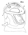
- an air filtration system and helmet assembly are generally disclosed at 10 and 12, respectively.
- the air filtration system 10 filters air between a head 14 and body 16 of a user and an environment external to the user and includes the helmet assembly 12 mounted to the head 14 of a user.
- the helmet assembly 12 distributes air about the head 14 of the user as will be described below. More specifically, the helmet assembly 12 distributes air toward both a front of the head 14, i.e., the face, of the user, and a back of the head 14, i.e., the neck, of the user.
- the helmet assembly 12 includes an inner structural shell 18 and an outer structural shell 20.
- the inner shell 18 includes a cover surface 22 and a rear facing 24 which extend to the outer shell 20.
- the cover surface 22 and rear facing 24 will be discussed further below.
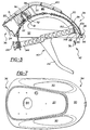
- the outer shell 20 is spaced apart from the inner shell 18 and extends from the inner shell 18 to define at least one air flow channel 26 between the inner and outer shells 18, 20.
- the subject invention may include more than one discrete air flow channel 26.
- the preferred embodiment includes a single unitary air flow channel 26 and the subject invention will be described below in terms of this air flow channel 26.
- the air flow channel 26 channels air about the head 14 of the user.
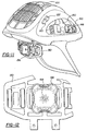
- the inner and outer shells 18, 20 form the air flow channel 26 from a two-sheet thermoforming process which improves the structural strength of the inner and outer shells 18, 20. More specifically, each of the inner and outer shells 18, 20 include an outer periphery 28, and in the two-sheet thermoforming process, the inner and outer shells 18, 20 are pinched together at their outer peripheries 28. The air flow channel 26 is subsequently thermoformed between the pinched outer peripheries 28. As shown best in Figure 7 , dissipation cavities 30 are disposed at opposite lateral sides of the inner and outer shells 18, 20 to provide for increased air release from the air flow channel 26 and from the user out through the helmet assembly 12.
- the helmet assembly 12 further includes a base section 32 having a front section 34 and a rear section 36.
- the inner and outer shells 18, 20 extend between the front and rear sections 34, 36 to define the air flow channel 26.
- the cover surface 22 and the rear facing 24 of the inner shell 18 extend to the outer shell 20 at the rear section 36 of the base section 32.
- a mounting cavity 38 is formed between the cover surface 22 of the inner shell 18 and the outer shell 20.
- the mounting cavity 38 will be discussed further below.
- the inner and outer shells 18, 20 form the base section 32. It is understood that the base section 32 is the portion of the helmet assembly 12 that is mounted over the head 14 of the user. As such, it is also understood that the front section 34 of the base section 32 is at the face of the user as the user wears the helmet assembly 12, and the rear section 36 of the base section 32 is at the neck of the user as the user wears the helmet assembly 12.
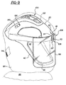
- the helmet assembly 12 also includes a facial section 40 extending from the base section 32 to define a facial opening 42.
- the facial section 40 of the helmet assembly 12 is a chin bar 44.
- the chin bar 44 is flexible and is formed of plastic.
- the chin bar may also be formed of a polypropylene component. The flexibility of the chin bar 44 protects the user's face and also absorbs impact when the user contacts an external object with the helmet assembly 12.
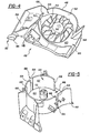
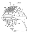
- the air filtration system 10 and helmet assembly 12 further include a fan module 46 mounted to at least one of the inner and outer shells 18, 20 and a scroll housing 48 mounted in the helmet assembly 12 adjacent the fan module 46. More specifically, both the fan module 46 and the scroll housing 48 are disposed within the mounting cavity 38 at the rear section 36 of the helmet assembly 12. Disposing the fan module 46 and the scroll housing 48 in the mounting cavity 38 is space-saving, reduces the overall weight of the helmet assembly 12 because additional mounting connections are not required, and minimizes strain and fatigue on the head 14 and the neck of the user.
- the fan module 46 includes a fan 50 and a motor 52 and is disposed at the rear section 36 of the base section 32.
- the fan 50 includes a plurality of curved blades 54 and a hub portion 56.
- the curved blades 54 of the fan 50 encourage air into the scroll housing 48.
- the motor 52 includes an output 58, or drive shaft, that is operatively connected to the fan 50 to drive the fan 50 at a plurality of rotational speeds correlating to an amount, or a volume, of air flowing into the air flow channel 26.
- the rotational speeds of the fan 50 can be measured in revolutions per minute (RPMs).
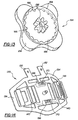
- the scroll housing 48 includes a base portion 60 and an outer wall 62 circumferentially extending around the base portion 60.
- the scroll housing 48 further includes at least one air inlet 64 and at least two air outlets 66.
- the scroll housing includes a plurality of air outlets 66.
- the scroll housing includes at least two air outlets 66.
- Other specific embodiments of the subject invention may also only include the fan module 46 without the scroll housing 48. In such embodiments, the at least one air inlet and the at least two air outlet can be described as components of the fan module 46.
- the motor 52 rotates the fan 50 to draw air into the air inlet 64 of the scroll housing 48 and distributes air out of the scroll housing 48 through the air outlet 66 or outlets 66 and into the air flow channel 26 where the air is distributed about the head 14 of the user.
- the scroll housing 48 also includes at least one air flow cutoff 68 which cuts the air as the fan 50 moves the air within the scroll housing 48. More specifically, as shown in the Figures, the subject invention incorporates several air flow cutoffs 68 in the scroll housing 48 to cut the air.
- a power supply 70 is incorporated in the subject invention to power the motor 52 to rotate the fan 50 via the motor output 58.
- the power supply 70 is a rechargeable DC battery.
- the power supply 70 is disposed within, i.e., integrated into, the helmet assembly 12.
- the power supply 70 is referred to as an integral power supply 71 as shown in Figure 3 .
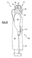
- the power supply 70 can be mounted to the body 16 of the user as shown in Figure 8 .
- the power supply 70 powers the motor 52 through pulse width modulation (PWM) which will be discussed further below.
- PWM pulse width modulation
- the design of the scroll housing 48 provides more efficient movement of air with less power being required from the power supply 70 overall. Furthermore, in addition to such reduced power requirements, the scroll housing 48 provides that sufficient air flow can be maintained with overall less air velocity. This results in a more quiet helmet assembly 12.
- the fan 50 of the fan module 46 is rotatably mounted to the base portion 60 of the scroll housing 48 within the outer wall 62 of the scroll housing 48 to draw air into the air inlet 64.
- the air inlet 64 of the scroll housing 48 is integrally formed within the outer shell 20 of the helmet assembly 12 for drawing air into the scroll housing 48.
- the air inlet 64 is not required to be integrally formed within the outer shell 20 of the helmet assembly 12. That is, in an alternative embodiment of the subject invention, an external structure, not shown in the Figures, can be mounted external to the helmet assembly 12 to establish the air inlet 64 of the scroll housing 48 for drawing air into the scroll housing 48.
- the scroll housing 48 further includes a support pedestal 72 protruding from the base portion 60.
- the support pedestal 72 is integrally formed as a part of the scroll housing 48 to protrude from the base portion 60.
- the support pedestal 72 can be a separate part. That is, the support pedestal 72 can be a separate part that is mounted or connected to the base portion 60 of the scroll housing 48 via connecting screws, snap-fit, and the like.
- the hub portion 56 of the fan 50 is rotatably mounted in the scroll housing 48 on the support pedestal 72 by screws or other fasteners.
- the motor 52 of the fan module 46 is mounted within an underside 74 of the support pedestal 72 between the support pedestal 72 and the cover surface 22 of the inner shell 18 for space-saving purposes in the helmet assembly 12.
- the underside 74 of the support pedestal 72 is essentially hollow.
- the cover surface 22 of the inner shell 18 operates as a motor cover to close the fan module 46 at the inner shell 18.
- the outer wall 62 of the scroll housing 48 is partitioned to define the air outlets 66.
- the subject invention is not limited to at least two air outlets 66. That is, the subject invention may include, for example, three or four air outlets 66.
- the air outlets 66 provide a complete balance of air as the air is distributed from the scroll housing 48 about the head 14 of the user.
- the helmet assembly 12 includes at least two helmet air exits 76, 78.
- the air outlets 66 are in fluid communication with the at least two helmet air exits 76, 78 to distribute the air from the outlets 66, which is in the air flow channel, toward the head of the user.
- the helmet assembly includes the at least two helmet air exits 76, 78 it is not critical that the scroll housing 48 include at least two air outlets 66. To the contrary, the scroll housing, in these embodiments, may only have at least one air outlet 66.
- the first 76 and second 78 air exits are respectively front and rear air exits in that they are disposed at the front and rear sections 34, 36 of the helmet assembly 12, respectively, to effectively distribute air toward both the face and neck of the user.
- the first and second air exits 76, 78 can be customized to distribute air toward any portion of the user's head.
- the first and second air exits 76, 78 can be side air exits such that air is distributed toward the side of the user's head.
- the subject invention will be described below only in terms of the front 76 and rear 78 air exits and will be numbered accordingly.
- the front air exit 76 is disposed at the front section 34 of the base section 32 for distributing air from the air flow channel 26 toward the front of the head 14 of the user
- the rear air exit 78 is disposed at the rear section 36 of the base section 32 for distributing air from the air flow channel 26 toward the back of the head 14 of the user.
- the rear air exit 78 is formed within the rear facing 24 for distributing air from the air flow channel 26 toward the back of the head 14 of the user.
- the air flow channel 26 defined between the inner and outer shells 18, 20 terminates at the front section 34 with the front air exit 76 and at the rear section 36 with the rear air exit 78. More specifically, the inner and outer shells 18, 20 converge toward the front section 34 of the base section 32 to define the front air exit 76.
- the front air exit 76 has an air deflection angle 80.
- the air deflection angle 80 is defined between the outer shell 20 and the inner shell 18 wherein the outer shell 20 angles toward the inner shell 18 at the front air exit 76 for proper deflection of air toward the front of the head 14 of the user.
- the air deflection angle 80 between the outer 20 and inner 18 shell is greater than zero, preferably between 25 - 35 degrees.
- the air flow channel 26 diverges outwardly upon approaching the front air exit 76.
- the convergence and divergence of the air flow channel 26 maintains a balanced flow of air about the user's head 14. Ultimately, this also has the effect of minimizing or even completely eliminating noise within the helmet assembly 12 due to the air flow.
- the subject invention incorporates at least one air bleed valve 82 in the scroll housing 48 to influence the amount, or the volume, of air flowing into the air flow channel 26 from each of the air outlets 66. It is to be understood that, although there is only one air bleed valve 82 shown in Figure 4 , the subject invention may alternatively incorporate more than one air bleed valve.
- the air bleed valve 82 influences the volume of air flowing to the rear air exit 78 thereby affecting the volume of air flowing to the rear air exit 78 that is distributed primarily toward the back of the head 14 of the user.
- the air bleed valve 82 includes a blade 84 that can be rotated to cover, i.e., close, the air outlet 66 of the scroll housing 48 nearest the rear air exit 78. If covered or closed, more air is moved to the front air exit 76 of the helmet assembly 12 and the volume of air flowing is constant, not variable.
- the air bleed valve 82 is mechanically controlled by a mechanical lever or knob 86 in order to manipulate the volume of air flowing into the air flow channel 26 from each of the air outlets 66.
- the air bleed valve 82 may alternatively be electronically controlled to manipulate the volume of air. Also, it is to be understood that the air bleed valve 82 is not required in the subject invention.
- the air filtration system 10 includes a gown 88 having a body portion 90 for covering at least a portion of the body 16 of the user and a head portion, or hood, 92 for covering the base section 32 of the helmet assembly 12, which houses the head 14 of the user. More specifically, the body portion 90 can extend downward to cover any portion of the body 16 of the user. For instance, the body portion 90 can extend downward to the shoulders of the user, or to the waist of the user, or to the ankles of the user.
- the head portion 92 of the gown 88 operates as a filter medium 94 to filter air between the user and the external environment.
- a skirt 93 is attached to the body portion 90 of the gown 88 exclusively at a front, not numbered, of the gown 88.
- skirt 93 which is typically sterile in the industry, is only attached at the front, i.e., does not encircle around a back of the gown 88, cost can be saved. Also, the skirt 93 is removably attached at the front of the body portion 90 of the gown 88 such that a particular user can decide whether to use the skirt 93 or not.
- the skirt 93 is attached to the gown 88 in any known manner in the industry including, but not limited to, adhesive tape.
- the facial section 40 of the helmet assembly 12, introduced above, also operates to maintain the gown 88 away from the head 14 of the user.
- the subject invention also includes a face shield 96 that permits the user to view through the head portion 92 of the gown 88 and the facial opening 42 of the helmet assembly 12.
- the face shield 96 is mounted to the head portion 92 of the gown 88 such that the face shield 96 covers the facial section 40 and the facial opening 42 of the helmet assembly 12 once the user dresses into the air filtration system 10. More specifically, the face shield 96 is sewn into the head portion 92 of the gown 88 to maintain a complete barrier between the user and the external environment.
- the facial opening 42 of the helmet assembly 12 essentially receives the face shield 96.
- the facial section 40 of the helmet assembly 12 includes a hook-and-loop fastener 98 to further facilitate attachment of the face shield 96 to the facial section 40 for covering the facial opening 42.
- the helmet assembly 12 further includes an intake grid 100 mounted to the outer shell 20.
- the intake grid 100 includes a top surface 102 spaced from the outer shell 20 of the helmet assembly 12 to retain the filter medium 94 away from the outer shell 20 and the fan 50. Furthermore, the intake grid 100 is contoured to the outer shell 20 between the front section 34 and the rear section 36 of the base section 32. This improves the effective seal between the gown 88 and the helmet assembly 12, and maximizes an effective intake area 104 for the filter medium 94 to filter air drawn into the scroll housing 48 by the fan 50.
- the controller 118 monitors the RPMs of the output 58 of the motor 52. More specifically, as set forth in the above method, the controller 118 monitors the voltage generated by the motor 52 to receive the RPM information of the output 58 of the motor 52. The controller 118 then converts the information from analog to digital simply by changing the voltage generated by the motor 52 into a digital value representative of the voltage. The controller 118 incorporated into the subject invention also recognizes a set point that is indicative of one of the plurality of rotational speeds of the fan 50. It is to be understood that the set point is indicative of the current rotational speed of the fan 50.
- a memory is included into the controller 118 for retaining the set point, i.e., the last rotational speed of the fan 50, when the power supply 70 is deactivated.
- the power supply 70 is deactivated either when the voltage in the power supply 70 drops to zero or the power supply 70 is disconnected and replaced. In other words, if the battery drains, or is disconnected for any reason, then a new battery can be used, and once connected the controller 118 will control the power supply 70 to rotate the fan 50 at the last set point It is understood that users may use the helmet assembly 12 over a period of time that is longer than the life of the battery, and that once the voltage of the battery drops below a useful value, the batter is replaced with a new battery.
- the controller 118 read the available voltage of the battery and instructs the switch to adjust, through PWM, the ON / OFF ratio to the motor 52 to maintain the predetermined air flow throughout the helmet assembly 12 that is established by the set point.
- the air filtration system 10 and helmet assembly 12 of the subject invention include a front-adjustable support 128 for the helmet assembly 12. Strain and torque on the head 14 and neck of the user is minimized by maintaining the weight of the fan 50 and motor 52 over the neck of the user even upon adjustment of the helmet assembly 12 to fit various sized heads.
- the front-adjustable support 128 includes a rear support 130 that rigidly extends from the rear section 36 of the base section 32. It is to be understood that the rear support 130 can be a separate part that is connected to the helmet assembly 12 or can be an integral part of the helmet assembly 12.
- the rear support 130 includes first and second rigid connectors 132 that connect the rear support 130 to the rear section 36.
- the rear support 130 is connected to and extends from the rear section 36 of the inner shell 18 and will described below in terms of the inner shell 18.
- the rear support 130 can connect to and extend from the rear section 36 of the outer shell 20 without varying the scope of the subject invention.
- an adjustment segment 134 having first 136 and second 138 sides is disclosed.
- the rear support 130 preferably includes the adjustment segment 134. That is, preferably the adjustment segment 134 is integral to, or the same part as, the rear support 130. However, the adjustment segment 134 can alternatively be a discrete component that is simply mounted to the rear support 130. In either situation, the adjustment segment 134 defines an adjustment aperture 140.
- the subject invention also includes a strap 142 flexibly connected to and extending from the front section 34 of the inner shell 18.
- the strap 142 includes a first end 144 disposed within the first side 136 of the adjustment segment 134, and a second end 146 disposed within the second side 138 of the adjustment segment 134.
- the adjustment aperture 140 defined by the adjustment segment 134 receives the first and second ends 144, 146 of the strap 142.
- the first end 144 is movably disposed within the first side 136 of the adjustment segment 134
- the second end 146 is movably disposed within the second side 138 of the adjustment segment 134.
- the first end 144 may be movably disposed within the first side 136 of the adjustment segment 134 and the second end 146 may be fixedly disposed within the second side 138 of the adjustment segment 134.
- the first end 144 may be fixedly disposed within the first side 136 of the adjustment segment 134 and the second end 146 may be movably disposed within the second side 138 of the adjustment segment 134.
- the strap 142 further includes a frontal portion 148 disposed between its first and second ends 144, 146 and opposite the adjustment segment 134 of the rear support 130. At least one hinge 150 extends from the frontal portion 148 of the strap 142 to flexibly connect the strap 142 to the front section 34 of the inner shell 18. Preferably, there are two hinges 150 that extend from the frontal portion 148 of the strap 142. In such a case, the two hinges 150 are connected to the front section 34 of the inner shell 18 and to the frontal portion 148 of the strap 142 equidistant from one another. A gap 152 exists between the frontal portion 148 of the strap 142 and the front section 34 of the inner shell 18.
- An adjustment device 154 is mounted to the adjustment segment 134 of the rear support 130.
- the adjustment device 154 is manipulated to pull the strap 142 from the front section 34 of the inner shell 18 to maintain the weight of the fan 50 and motor 52 over the user's neck. This will described below.
- the adjustment device 154 is further defined as an adjustment knob 156.
- the adjustment knob 156 is rotatably mounted from and extends into the adjustment aperture 140 of the rear support 130 to engage the first and second ends 144, 146 of the strap 142.
- the adjustment knob 156 includes a pinion 158 extending into the adjustment aperture 140.
- the first end 144 of the strap 142 includes a first rack 160 and the second end 146 of the strap 142 includes a second rack 162.
- the pinion 158 of the adjustment knob 156 extends into the adjustment aperture 140 to engage and move the first and second racks 160, 162 upon rotation of the adjustment knob 156.
- the adjustment device 154 engages the first and second ends 144, 146 of the strap 142 to manipulate the first and second ends 144, 146 toward each other. This tightens the strap 142 and pulls the strap 142 from the front section 34 as the rear support 130 remains fixed relative to both the rear section 36 and the strap 142.
- the adjustment device 154 also engages the first and second ends 144, 146 of the strap 142 to manipulate the first and second ends 144, 146 away from each other. This loosens the strap 142 and pushes the strap 142 toward the front section 34 as the rear support 130 remains fixed relative to both the rear section 36 and the strap 142.
- both the first and second ends 144, 146 can move toward each other.
- the subject invention may be 'single-end adjustable.
- the first and second ends may be manipulated toward each other even if the first end 144 is fixed and the second end 146 is the only end of the strap 142 that is manipulated, i.e., moved, by the adjustment device 154, or even if the second end 146 is fixed and the first end 144 is the only end of the strap 142 that is manipulated, i.e., moved, by the adjustment device 154.
- the hinges 150 In operation, as the strap 142 is tightened by the adjustment device 154, the hinges 150 flex to increase the gap 152 between the frontal portion 148 of the strap 142 and the front section 34 of the inner shell 18. Because the strap 142 only moves relative to the front section 34 of the inner shell 18, the weight of the fan module 46 and scroll housing 48 is maintained over the neck of the user when the helmet assembly 12 is adjusted to fit a smaller sized head 14. Alternatively, if the strap 142 is loosened, the hinges 150 relax to decrease the gap 152. As such, the weight of the fan module 46 and scroll housing 48 is maintained over the neck of the user when the helmet assembly 12 is adjusted to fit a larger sized head 14. In a sense, the helmet assembly 12 remains stationary relative to the user's head 14 and neck upon adjustment, only the strap 142 moves within the helmet assembly 12.
- the adjustment knob 156 additionally includes an inner surface 164 facing the rear support 130 of the helmet assembly 12.
- the inner surface 164 includes a plurality of teeth 166.
- the teeth 166 form a ring around the inner surface 164.
- a flexible support bar 168 is molded into and extends from the rear support 130.
- the flexible support bar 168 includes at least one locking detent 170 mating with the teeth 166 of the adjustment knob 156 to lock the strap 142 relative to the rear support 130.
- more than one detent 170 can be utilized.
- the preferred embodiment of the subject invention includes two flexible support bars 168 to lock the strap 142 relative to the rear support 130.
- the flexible support bars 168 flex to disengage the detent 170 from the teeth 166 of the adjustment knob 156 upon manipulation of the adjustment knob 156 such that the strap 142 is allowed to move relative to the rear support 130.
- the flexible support bars 168 act like a spring and rebound to force the detent 170 back into engagement with the teeth 166.
Landscapes
- Health & Medical Sciences (AREA)
- General Health & Medical Sciences (AREA)
- Physical Education & Sports Medicine (AREA)
- Engineering & Computer Science (AREA)
- Textile Engineering (AREA)
- Pulmonology (AREA)
- Business, Economics & Management (AREA)
- Emergency Management (AREA)
- Helmets And Other Head Coverings (AREA)
- Professional, Industrial, Or Sporting Protective Garments (AREA)
- Respiratory Apparatuses And Protective Means (AREA)
Claims (41)
- Ensemble formant un casque (12) d'un système de filtration d'air (10) à monter sur la tête (14) d'un utilisateur pour distribuer de l'air autour de la tête (14) de l'utilisateur, ledit ensemble (12) comprenant :une coque de structure interne (18) ;une coque de structure externe (20) s'étendant à partir de ladite coque de structure interne (18) pour définir au moins un canal d'air (26) entre lesdites coques interne (18) et externe (20) pour acheminer l'air autour de la tête (14) de l'utilisateur ; etun module de ventilation (46) monté sur au moins une desdites coques interne (18) et externe (20) ;ledit ensemble (12) caractérisé par un carter à volute (48) monté de façon adjacente audit module de ventilation (46) et incluant au moins une entrée d'air (64) et au moins deux sorties d'air (66) avec une desdites sorties d'air (66) permettant à l'air d'être distribué dans une première direction et une autre des desdites sorties d'air (66) permettant à l'air d'être distribué dans une deuxième direction qui est différente de ladite première direction, dans lequel ledit module de ventilation (46) aspire l'air dans ladite entrée d'air (64) dudit carter à volute (48) et distribue l'air hors dudit carter à volute (48) à travers lesdites sorties d'air (66) et dans ledit canal d'air (26) dans lesdites différentes directions pour distribuer l'air autour de la tête (14) de l'utilisateur.
- Ensemble (12) selon la revendication 1, dans lequel ledit carter à volute (48) comprend en outre une partie de base (60) et une paroi externe (62) s'étendant de manière circonférentielle autour de ladite partie de base (60).
- Ensemble (12) selon la revendication 2, dans lequel ladite paroi externe (62) dudit carter à volute (48) est divisée pour définir lesdites au moins deux sorties d'air (66).
- Ensemble (12) selon la revendication 3, comprenant en outre une section de base (32) ayant une section avant (34) et une section arrière (36), et une section faciale (40) s'étendant à partir de ladite section de base (32) pour définir une ouverture faciale.
- Ensemble (12) selon la revendication 4, dans lequel lesdites coques interne (18) et externe (20) se s'étendent entre lesdites sections avant (34) et arrière (36) de ladite section de base (32) pour définir ledit canal d'air (26).
- Ensemble (12) selon la revendication 5 comprenant en outre une sortie d'air frontale (76) disposée au niveau de ladite section avant (34) de ladite section de base (32) pour distribuer de l'air à partir dudit canal d'air (26) vers l'avant de la tête (14) de l'utilisateur, et une sortie d'air arrière (78) disposée au niveau de ladite section arrière (36) de ladite section de base (32) pour distribuer de l'air à partir dudit canal d'air (26) vers l'arrière de la tête (14) de l'utilisateur.
- Ensemble (12) selon la revendication 6, dans lequel lesdites au moins deux sorties d'air (66) dudit carter à volute (48) sont en communication fluidique avec lesdites sorties d'air frontale (76) et arrière (78) pour distribuer l'air vers l'avant et l'arrière de la tête (14) de l'utilisateur, respectivement.
- Ensemble (12) selon la revendication 7, dans lequel lesdites coques interne (18) et externe (20) convergent vers ladite section avant (34) de ladite section de base (32) pour définir ladite sortie d'air frontale (76).
- Ensemble (12) selon la revendication 8 comprenant en outre un angle de déflection d'air (80) défini par ladite coque externe (20) donnant une orientation vers ladite coque interne (18) au niveau de ladite sortie d'air frontale (76) pour une déflection appropriée de l'air vers l'ayant de la tête (14) de l'utilisateur.
- Ensemble (12) selon la revendication 9, dans lequel ledit angle de déflection d'air (80) est supérieur à zéro.
- Ensemble (12) selon la revendication 9, dans lequel ledit angle de déflection d'air (80) est compris entre 25 et 35 degrés.
- Ensemble (12) selon la revendication 4, comprenant en outre une grille de prise d'air (100) montée au niveau de ladite coque externe (20), ladite grille de prise d'air (100) étant adaptée pour un usage avec une blouse (88) qui couvre ladite section de base (32) et fonctionne comme un moyen de filtrage (94) pour filtrer l'air aspiré dans ledit carter à volute (48).
- Ensemble (12) selon la revendication 12, dans lequel ladite grille de prise d'air (100) comprend en outre une surface supérieure éloignée de ladite coque externe (20) pour maintenir le moyen de filtrage (94) loin de ladite coque externe (20) et dudit module de ventilation (46).
- Ensemble (12) selon la revendication 13, dans lequel ladite grille de prise d'air (100) est définie par les contours de ladite coque externe (20) entre ladite section avant (34) et ladite section arrière (36) de ladite section de base (32) pour optimiser un secteur de prise d'air efficace pour que le moyen de filtrage (94) filtre l'air aspiré dans ledit carter à volute (48).
- Ensemble (12) selon la revendication 14, comprenant en outre des cavités de dissipation (30) disposées sur les côtés latéraux opposés desdites coques interne (18) et externe (20), lesdites cavités (30) fournissant une libération d'air accrue à partir dudit canal d'air (26) et de l'utilisateur à travers le moyen de filtrage (94).
- Ensemble (12) selon la revendication 6, dans lequel ladite coque interne (18) comprend en outre une surface d'habillage (22) et une partie arrière (24), ladite surface d'habillage (22) et ladite partie arrière (24) s'étendant jusqu'à ladite coque externe (20) au niveau de ladite section arrière (36) de ladite section de base (32).
- Ensemble (12) selon la revendication 16, dans lequel ladite sortie d'air arrière (78) est formée dans ladite partie arrière (24) pour distribuer de l'air à partir dudit canal d'air (26) vers l'arrière de la tête (14) de l'utilisateur.
- Ensemble (12) selon la revendication 16, comprenant en outre une cavité de fixation (38) entre ladite surface d'habillage (22) et ladite coque externe (20) au niveau de ladite section arrière (36) de ladite section de base (32).
- Ensemble (12) selon la revendication 18, dans lequel ledit module de ventilation (46) et ledit carter à volute (48) sont disposés intégralement dans ladite cavité de fixation (38) au niveau de ladite section arrière (36) pour réduire au minimum la pression sur le cou de l'utilisateur.
- Ensemble (12) selon la revendication 19, dans lequel ledit module de ventilation (46) comprend un ventilateur (50) pour aspirer l'air dans ladite entrée d'air (64) et un moteur (52) pour faire tourner ledit ventilateur (50).
- Ensemble (12) selon la revendication 20 comprenant en outre une alimentation électrique (70) actionnant ledit moteur (52) pour faire tourner ledit ventilateur (50).
- Ensemble (12) selon la revendication 21, dans lequel ladite alimentation électrique (70) actionne ledit moteur (52) par une modulation d'impulsions en durée.
- Ensemble (12) selon la revendication 20, dans lequel ledit ventilateur est monté de manière rotative à ladite partie de base (60) dudit carter à volute (48) dans ladite paroi externe (62) pour que ledit ventilateur (50) aspire l'air dans ladite entrée d'air (64) dudit carter à volute (48).
- Ensemble (12) selon la revendication 23, dans lequel ladite entrée d'air (64) dudit carter à volute (48) est formée de manière intégrale dans ladite coque externe (20) pour aspirer l'air dans ledit carter à volute (48).
- Ensemble (12) selon la revendication 24, comprenant en outre un socle de support (72) dépassant de ladite partie de base (60), ledit ventilateur (50) étant monté de manière rotative dans ledit carter à volute (48) sur ledit socle de support (72) pour aspirer l'air dans ladite entrée d'air (64) dudit carter à volute (48).
- Ensemble (12) selon la revendication 25, dans lequel ledit moteur (52) est monté dans une partie de dessous dudit socle de support (72) entre ledit socle de support (72) et ladite surface d'habillage (22) de ladite coque interne (18).
- Ensemble (12) selon la revendication 12, dans lequel ladite section faciale (40) s'étendant à partir de ladite section de base (32) est encore définie comme une mentonnière (44) s'étendant à partir de ladite section de base (32) pour définir ladite ouverture faciale et pour maintenir la blouse (88) loin de la tête (14) de l'utilisateur.
- Ensemble (12) selon la revendication 27, dans lequel ladite mentonnière (44) est flexible.
- Ensemble (12) selon la revendication 27, dans lequel ladite mentonnière flexible (44) est constituée de plastique.
- Ensemble (12) selon la revendication 7 comprenant en outre au moins un clapet de régulation d'air (82) disposé dans ledit carter à volute (48) pour influencer un volume d'air s'écoulant dans ledit canal d'air (26) à partir de chacune desdites au moins deux sorties d'air (66).
- Ensemble (12) selon la revendication 30 dans lequel ledit clapet de régulation d'air (82) est disposé dans ledit carter à volute (48) pour influencer le volume d'air s'écoulant vers ladite sortie d'air arrière (78) pour distribuer l'air vers l'arrière de la tête (14) de l'utilisateur.
- Ensemble (12) selon la revendication 30, dans lequel ledit clapet de régulation d'air (82) est commandé mécaniquement pour manipuler le volume d'air.
- Ensemble (12) selon la revendication 30, dans lequel ledit clapet de régulation d'air (82) est commandé électroniquement pour manipuler le volume d'air.
- Ensemble (12) selon la revendication 1, dans lequel lesdites coques de structure interne (18) et externe (20) forment ledit canal d'air (26) à partir d'un processus de thermoformage de deux feuilles.
- Ensemble (12) selon la revendication 34, dans lequel chacune desdites coques de structure interne (18) et externe (20) comprend une périphérie externe, lesdites coques interne (18) et externe (20) s'étranglant ensemble au niveau desdites périphéries externes.
- Ensemble (12) selon la revendication 35, dans lequel ledit canal d'air (26) est thermoformé entre lesdites périphéries externes étranglées desdites coques interne (18) et externe (20).
- Système de filtration d'air (10) pour filtrer l'air entre la tête et le corps d'un utilisateur et un environnement externe à l'utilisateur, ledit système de filtration d'air comprenant :un ensemble formant un casque (12) selon la revendication 1 ;une blouse (88) comprenant une partie de corps (90) pour recouvrir au moins une partie du corps de l'utilisateur et une partie de tête (92) pour recouvrir ledit ensemble formant un casque (12), ladite partie de tête (92) de ladite blouse (88) fonctionnant comme moyen de filtrage (94) pour filtrer l'air entre l'utilisateur et l'environnement externe ; etun masque de protection faciale (96) monté sur ladite partie de tête (92) de ladite blouse (88) pour recouvrir ladite section faciale dudit ensemble formant un casque permettant ainsi à l'utilisateur de regarder à travers ladite partie de tête de ladite blouse.
- Ensemble (12) selon la revendication 1, dans lequel ladite première direction est encore définie comme une direction avant de telle sorte que celle desdites sorties d'air (66) permet à l'air d'être distribué vers l'avant de la tête (14) de l'utilisateur, et dans lequel ladite seconde direction est encore définie comme une direction arrière telle que l'autre desdites sorties d'air (66) permet à l'air d'être distribué vers l'arrière de la tête (14) de l'utilisateur.
- Ensemble formant un casque (12) d'un système de filtration d'air (10) à monter sur la tête (14) d'un utilisateur pour distribuer de l'air autour de la tête (14) de l'utilisateur, ledit ensemble (12) comprenant :une coque de structure interne (18) ;une coque de structure externe (20) s'étendant à partir de ladite coque de structure interne (18) pour définir au moins un canal d'air (26) entre lesdites coques interne (18) et externe (20) pour acheminer l'air autour de la tête (14) de l'utilisateur ; etun module de ventilation (46) monté sur au moins une desdites coques interne (18) et externe (20) ;ledit ensemble (12) caractérisé en ce qu'il comprend au moins une entrée d'air (64) et au moins deux sorties d'air (66) étant des composants dudit module de ventilation (46), ledit module de ventilation (46) aspirant l'air dans ladite au moins une entrée d'air (64) et distribuant l'air hors desdites sorties d'air (66) et dans ledit canal d'air (26) pour distribuer l'air autour de la tête (14) de l'utilisateur dans au moins deux directions différentes.
- Ensemble selon la revendication 39, comprenant en outre une sortie d'air frontale en communication fluidique avec ledit au moins un canal d'air (26) pour distribuer de l'air à partir dudit canal d'air (26) vers l'avant de la tête (14) de l'utilisateur et une sortie d'air arrière en communication avec ledit au moins un canal d'air (26) pour distribuer de l'air dudit canal d'air (26) vers l'arrière de la tête (14) de l'utilisateur.
- Système de filtration d'air (10) pour filtrer l'air entre la tête et le corps d'un utilisateur et un environnement externe à l'utilisateur, ledit système de filtration d'air comprenant :un ensemble formant un casque (12) selon la revendication 39 ;une blouse (88) comprenant une partie de corps (90) pour recouvrir au moins une partie du corps de l'utilisateur et une partie de tête (92) pour recouvrir ledit ensemble formant un casque (12), ladite partie de tête (92) de ladite blouse (88) fonctionnant comme moyen de filtrage (94) pour filtrer l'air entre l'utilisateur et l'environnement externe ; etun masque de protection faciale (96) monté sur ladite partie de tête (92) de ladite blouse (88) pour recouvrir ladite section faciale dudit ensemble formant un casque permettant ainsi à l'utilisateur de regarder à travers ladite partie de tête de ladite blouse.
Priority Applications (2)
| Application Number | Priority Date | Filing Date | Title |
|---|---|---|---|
| EP08001739A EP1925222B1 (fr) | 2000-01-18 | 2001-01-18 | Ensemble d'une blouse et d'un casque |
| EP10012567.3A EP2316289B1 (fr) | 2000-01-18 | 2001-01-18 | Système de protection personnelle comportant un casque, une capuche et un ensemble pour aligner la capuche et le casque |
Applications Claiming Priority (3)
| Application Number | Priority Date | Filing Date | Title |
|---|---|---|---|
| US17695800P | 2000-01-18 | 2000-01-18 | |
| US176958P | 2000-01-18 | ||
| PCT/US2001/001802 WO2001052675A2 (fr) | 2000-01-18 | 2001-01-18 | Systeme de filtration d'air comprenant un ensemble casque |
Related Child Applications (1)
| Application Number | Title | Priority Date | Filing Date |
|---|---|---|---|
| EP08001739A Division EP1925222B1 (fr) | 2000-01-18 | 2001-01-18 | Ensemble d'une blouse et d'un casque |
Publications (3)
| Publication Number | Publication Date |
|---|---|
| EP1286604A2 EP1286604A2 (fr) | 2003-03-05 |
| EP1286604A4 EP1286604A4 (fr) | 2004-12-15 |
| EP1286604B1 true EP1286604B1 (fr) | 2008-04-30 |
Family
ID=22646597
Family Applications (2)
| Application Number | Title | Priority Date | Filing Date |
|---|---|---|---|
| EP01908633A Expired - Lifetime EP1286604B1 (fr) | 2000-01-18 | 2001-01-18 | Systeme de filtration d'air comprenant un ensemble casque avec au moins deux sorties d'air pour distribuer l'air autour de la tête d'un utilisateur |
| EP10012567.3A Expired - Lifetime EP2316289B1 (fr) | 2000-01-18 | 2001-01-18 | Système de protection personnelle comportant un casque, une capuche et un ensemble pour aligner la capuche et le casque |
Family Applications After (1)
| Application Number | Title | Priority Date | Filing Date |
|---|---|---|---|
| EP10012567.3A Expired - Lifetime EP2316289B1 (fr) | 2000-01-18 | 2001-01-18 | Système de protection personnelle comportant un casque, une capuche et un ensemble pour aligner la capuche et le casque |
Country Status (6)
| Country | Link |
|---|---|
| US (4) | US6481019B2 (fr) |
| EP (2) | EP1286604B1 (fr) |
| JP (3) | JP4508513B2 (fr) |
| AT (1) | ATE393579T1 (fr) |
| DE (1) | DE60133811T2 (fr) |
| WO (1) | WO2001052675A2 (fr) |
Cited By (2)
| Publication number | Priority date | Publication date | Assignee | Title |
|---|---|---|---|---|
| US8261375B1 (en) | 2003-06-19 | 2012-09-11 | Reaux Brian K | Method of forming a protective covering for the face and eyes |
| WO2022009228A1 (fr) * | 2020-07-07 | 2022-01-13 | Somaiya Vidyavihar | Combinaison d'équipement de protection personnelle confortable (ppe) ayant un dispositif d'aspiration. |
Families Citing this family (134)
| Publication number | Priority date | Publication date | Assignee | Title |
|---|---|---|---|---|
| EP1286604B1 (fr) * | 2000-01-18 | 2008-04-30 | Stryker Corporation | Systeme de filtration d'air comprenant un ensemble casque avec au moins deux sorties d'air pour distribuer l'air autour de la tête d'un utilisateur |
| FR2804289B1 (fr) * | 2000-01-28 | 2002-08-16 | Gallet Sa | Dispositif de reglage du tour de tete pour casque de protection |
| US7934497B1 (en) * | 2001-11-19 | 2011-05-03 | The United States Of America As Represented By The Secretary Of The Army | Modular helmet-mask assembly |
| US6752146B1 (en) * | 2001-12-10 | 2004-06-22 | Boris Altshuler | Civilian anti-terrorist attack gas mask |
| US6792944B1 (en) * | 2002-02-26 | 2004-09-21 | Pabban Development Inc. | Air filtration and control system including headgear |
| US6751807B2 (en) * | 2002-03-26 | 2004-06-22 | Depuy Orthopaedics, Inc. | Piezo fan for ventilated garment |
| US20030182710A1 (en) * | 2002-03-26 | 2003-10-02 | Klotz Conrad Lee | Protective garment |
| US20050121031A1 (en) * | 2002-08-06 | 2005-06-09 | Ebersole John F.Jr. | Impact-protected advanced ruggedized augmented reality instrumented self contained breathing apparatus |
| FR2848291B1 (fr) * | 2002-12-06 | 2005-02-04 | Delta Prot | Bloc de ventilation pour vetement comme un scaphandre ou analogue |
| US6826783B1 (en) * | 2003-01-30 | 2004-12-07 | The United States Of America As Represented By The Secretary Of The Army | Chemical/biological helmet |
| US7810492B2 (en) * | 2003-03-27 | 2010-10-12 | Helmet Integrated Systems Limited | Respirator |
| US7275535B1 (en) * | 2003-06-23 | 2007-10-02 | Robert Brockman | Respiration hood useful in biological, radiological and chemical emergencies |
| US20050108813A1 (en) * | 2003-07-10 | 2005-05-26 | Cylena Medical Technologies Inc. | Protective apparel spacers and low resistance air flow |
| US20070192947A1 (en) * | 2003-07-10 | 2007-08-23 | Cylena Medical Technologies Inc. | Protective apparel with improved doffing |
| US6990691B2 (en) * | 2003-07-18 | 2006-01-31 | Depuy Products, Inc. | Head gear apparatus |
| US7156093B2 (en) * | 2003-09-18 | 2007-01-02 | E. D. Bullard Company | Inflatable respirator hood |
| US6918141B2 (en) * | 2003-09-23 | 2005-07-19 | Pabbon Development, Inc. | Protective headgear system |
| US7246382B2 (en) * | 2004-01-09 | 2007-07-24 | Cylena Medical Technology, Inc. | Handwear that improves protective apparel doffing |
| US7222374B2 (en) * | 2004-05-26 | 2007-05-29 | Bell Sports, Inc. | Head gear fitting system |
| US20050284470A1 (en) * | 2004-06-29 | 2005-12-29 | Chengping Wei | Method and apparatus for micro-environment control |
| US7111329B2 (en) * | 2004-06-29 | 2006-09-26 | Bell Sports, Inc. | Helmet reinforcement system |
| US7043772B2 (en) * | 2004-08-31 | 2006-05-16 | E. D. Bullard Company | Ratchet mechanism with unitary knob and pinion construction |
| US7357135B2 (en) * | 2004-09-08 | 2008-04-15 | Steel Grip, Inc. | Protective hood with fan assembly |
| US20060053527A1 (en) * | 2004-09-14 | 2006-03-16 | Schneider Robert E | Modular hat |
| US7114194B2 (en) * | 2004-09-14 | 2006-10-03 | Thomas A. English | Safety helmet having a ventilation assembly |
| EP1865799B1 (fr) | 2005-03-24 | 2010-06-09 | Stryker Corporation | Systeme de protection personnel |
| US20060283455A1 (en) * | 2005-06-15 | 2006-12-21 | Walker Garry J | Convertible respiratory hood assembly |
| US8020219B2 (en) | 2005-07-01 | 2011-09-20 | Bell Sports, Inc. | Strap anchor system and method |
| AU2013200577B8 (en) * | 2005-07-14 | 2014-11-13 | Stryker Corporation | Medical/surgical personal protection system, including a light source positioned so that heat generated thereby carried away therefrom, and head unit and hood for use in same |
| AU2006270252B2 (en) | 2005-07-14 | 2012-08-30 | Stryker Corporation | Head unit, having a head band and a ventilation unit, for a medical/surgical personal protection system |
| AU2012233043B2 (en) * | 2005-07-14 | 2014-04-24 | Stryker Corporation | Medical/surgical personal protection system including a hood having a face shield of varying curvature |
| CA2618982C (fr) * | 2005-08-09 | 2014-08-05 | Viasys Holdings Inc. | Ensemble couvre-chef protecteur chirurgical comprenant un systeme de ventilation a haut volume |
| US7937775B2 (en) | 2005-08-09 | 2011-05-10 | Microtek Medical, Inc. | Surgical protective head gear assembly including high volume air delivery system |
| US9756893B2 (en) * | 2005-08-31 | 2017-09-12 | Bell Sports, Inc. | Integrated fit and retention system |
| US20070061946A1 (en) * | 2005-09-21 | 2007-03-22 | Webb Nicholas J | Fan-based cooler for head-protection gear |
| US20070235031A1 (en) * | 2006-03-31 | 2007-10-11 | 3M Innovative Properties Company | Full face respiratory protection device |
| US8584265B2 (en) * | 2006-04-18 | 2013-11-19 | 3M Innovative Properties Company | Head suspension system and headgear with replaceable headband bridge and method of adjusting same |
| US20070251527A1 (en) * | 2006-04-21 | 2007-11-01 | Tiara Medical Systems, Inc. | Self-contained respiratory therapy apparatus for enhanced patient compliance and therapeutic efficacy |
| US20070277294A1 (en) * | 2006-05-30 | 2007-12-06 | Green Lawrence J | Protective headgear system with filter protector |
| US7861719B1 (en) * | 2006-09-19 | 2011-01-04 | The United States Of America As Represented By The Secretary Of The Army | High surface area chemical/biological air-purifying filter |
| US7802318B2 (en) * | 2006-10-24 | 2010-09-28 | Chun-Nan Chen | Helmet having cooling fan device |
| US8161576B2 (en) * | 2007-02-01 | 2012-04-24 | Sellstrom Manufacturing Company | Protective headgear assembly |
| US8020552B2 (en) * | 2007-02-26 | 2011-09-20 | Microtek Medical, Inc. | Helmets and methods of making and using the same |
| WO2008118768A1 (fr) | 2007-03-23 | 2008-10-02 | 3M Innovative Properties Company | Appareil d'apport d'air pour casque respiratoire |
| JP5295137B2 (ja) | 2007-03-23 | 2013-09-18 | スリーエム イノベイティブ プロパティズ カンパニー | レスピレーターの空気流制御システム |
| CN101815557B (zh) | 2007-10-05 | 2012-12-19 | 3M创新有限公司 | 呼吸器流量控制设备和方法 |
| AU2008321312B2 (en) * | 2007-11-12 | 2012-11-29 | 3M Innovative Properties Company | Respirator assembly with air flow direction control |
| US8234722B2 (en) | 2007-12-14 | 2012-08-07 | Stryker Corporation | Personal protection system with head unit having easy access controls and protective covering having glare avoiding face shield |
| US8136170B2 (en) * | 2008-02-05 | 2012-03-20 | Dean DiPaola | Powered helmet with visor defogging element and accessories |
| US20100050324A1 (en) * | 2008-09-02 | 2010-03-04 | Bell Sports, Inc. | Height-Adjustable Fit System |
| WO2010080709A1 (fr) | 2009-01-08 | 2010-07-15 | Hancock Medical | Systèmes de pression des voies respiratoires positifs intermittents et autonomes, et méthodes de traitement de l'apnée du sommeil, du ronflement et d'autres troubles respiratoires |
| CN107989814B (zh) * | 2009-11-19 | 2020-07-07 | 瑞思迈发动机及马达技术股份有限公司 | 鼓风机 |
| EP2556260B1 (fr) * | 2010-04-06 | 2018-08-15 | 3M Innovative Properties Company | Ventilateur radial présentant un profil en forme de spirale |
| US20170031525A1 (en) | 2010-05-14 | 2017-02-02 | Racing Optics, Inc. | Touch screen shield |
| US9428237B2 (en) | 2010-09-01 | 2016-08-30 | Peer Toftner | Motorcycle with adjustable geometry |
| US8327846B2 (en) | 2011-02-08 | 2012-12-11 | Hancock Medical, Inc. | Positive airway pressure system with head position control |
| US10448685B2 (en) | 2011-03-22 | 2019-10-22 | Medline Industries, Inc. | Protective apparel and support apparatus and method of use |
| US9480290B2 (en) | 2011-03-22 | 2016-11-01 | Medline Industries, Inc. | Protective apparel and support apparatus and method of use |
| WO2012129396A1 (fr) | 2011-03-22 | 2012-09-27 | Medline Industries, Inc. | Vêtement de protection et appareil de support |
| US9360016B2 (en) * | 2011-12-01 | 2016-06-07 | Rodney L. Hamilton | Body cooling system |
| US9155923B2 (en) | 2011-12-06 | 2015-10-13 | East Carolina University | Portable respirators suitable for agricultural workers |
| US8899227B2 (en) | 2011-12-15 | 2014-12-02 | 3M Innovative Properties Company | Air filtration device having subsections lacking fluid communication |
| US8887719B2 (en) | 2011-12-15 | 2014-11-18 | 3M Innovative Properties Company | Air filtration device having tuned air distribution system |
| US20140150163A1 (en) * | 2012-04-24 | 2014-06-05 | James Ronald Hatton | Fan Assembly for a Hat |
| WO2014031671A1 (fr) * | 2012-08-20 | 2014-02-27 | Jamart Tt, Llc | Ensemble respirateur |
| KR101430114B1 (ko) * | 2012-10-16 | 2014-08-14 | 주식회사유풍 | 사이즈 조절장치를 이용한 모자 |
| WO2014117179A1 (fr) | 2013-01-28 | 2014-07-31 | Hancock Medical, Inc. | Dispositifs et procédés de commande de position destinés à être utilisés avec des systèmes de pression de voie aérienne positive |
| WO2014160149A2 (fr) * | 2013-03-14 | 2014-10-02 | Stryker Corporation | Système de protection personnelle médical/chirurgical comprenant une lumière ultraviolette pour purifier l'air aspiré dans le système |
| USD748896S1 (en) * | 2013-04-15 | 2016-02-09 | Clay Edward James Caird | Headgear |
| US10709911B2 (en) | 2013-09-27 | 2020-07-14 | Zimmer Surgical, Inc. | Surgical helmet |
| NL2011579C2 (nl) | 2013-10-09 | 2015-04-13 | Arbin Care Products B V | Filtermasker. |
| KR101527288B1 (ko) * | 2013-10-28 | 2015-06-09 | 전성남 | 다기능 안전모 |
| US10470505B2 (en) | 2014-05-07 | 2019-11-12 | Medline Industries, Inc. | Protective apparel system with impervious protection |
| US9295297B2 (en) | 2014-06-17 | 2016-03-29 | Racing Optics, Inc. | Adhesive mountable stack of removable layers |
| US10881829B2 (en) | 2014-08-18 | 2021-01-05 | Resmed Inc. | Portable pap device with humidification |
| US11166514B2 (en) * | 2015-01-26 | 2021-11-09 | Mohammed A. Hajianpour | Helmet/Hood assembly structure and method to prepare for use |
| US11166515B1 (en) | 2015-01-26 | 2021-11-09 | Mohammed Ali Hajianpour | Helmet/hood assembly structure and method of use thereof |
| USD776802S1 (en) | 2015-03-06 | 2017-01-17 | Hancock Medical, Inc. | Positive airway pressure system console |
| JP5840807B1 (ja) * | 2015-03-20 | 2016-01-06 | 加賀産業株式会社 | 頭部保護用ヘルメット |
| CN104687543B (zh) * | 2015-03-30 | 2016-06-22 | 北京中科盛康科技有限公司 | 一种医用个人防护服 |
| CN104720155A (zh) * | 2015-04-03 | 2015-06-24 | 王金成 | 人工关节手术专用全包围手术衣 |
| US10548363B2 (en) | 2015-08-24 | 2020-02-04 | Bell Sports, Inc. | Helmet dampening fit system |
| WO2017053232A1 (fr) * | 2015-09-21 | 2017-03-30 | Stryker Corporation | Système de protection individuelle comprenant une bande de refroidissement |
| CN105167301B (zh) * | 2015-09-25 | 2023-07-25 | 郑州大学 | 一种用于骑行的智能安全防污染头盔 |
| US9551405B1 (en) * | 2015-11-10 | 2017-01-24 | Tung-Cheng Chen | Length adjusting device |
| KR102419424B1 (ko) * | 2015-12-11 | 2022-07-11 | 울산과학기술원 | 웨어러블 공기청정기 |
| CN109068784B (zh) * | 2016-01-07 | 2021-08-20 | Thi总医疗创新公司 | 具有非接触控制的可穿戴屏障系统、设备和方法 |
| EP3442637B1 (fr) | 2016-04-12 | 2022-10-19 | 3M Innovative Properties Company | Procédé de commande d'un respirateur purificateur d'air électrique |
| US11413479B2 (en) | 2016-04-12 | 2022-08-16 | 3M Innovative Properties Company | Method of controlling a powered air purifying respirator |
| PT3445197T (pt) * | 2016-04-18 | 2020-03-11 | Stryker Corp | Sistema de protecção individual que inclui um capuz com um escudo facial transparente |
| JP2019518520A (ja) | 2016-05-19 | 2019-07-04 | ハンコック メディカル, インコーポレイテッド | 位置閉塞性睡眠時無呼吸検出システム |
| WO2017214670A1 (fr) * | 2016-06-14 | 2017-12-21 | Darryl Rodney Flack | Casque avec zone d'écrasement de menton et ventilation intégrée |
| CN106072960B (zh) * | 2016-07-13 | 2023-03-14 | 杭州克霾环保科技有限公司 | 一种防雾霾帽 |
| WO2018057920A1 (fr) | 2016-09-23 | 2018-03-29 | Pavalarajan Ganesh B | Casque chirurgical |
| US11051984B2 (en) * | 2016-10-13 | 2021-07-06 | Otex Protective, Inc. | Ventilation unit and controller device |
| US10980305B2 (en) * | 2017-10-05 | 2021-04-20 | Honeywell International Inc. | Length adjustable shroud usable with helmet and earmuffs |
| US10384084B2 (en) * | 2017-10-18 | 2019-08-20 | Stryker Corporation | Personal protection system with control member |
| US10750800B2 (en) | 2018-01-26 | 2020-08-25 | Stryker Corporation | Surgical apparel system |
| CA183750S (en) * | 2018-04-04 | 2019-11-15 | Tecmen Electronics Co Ltd | Protective helmet |
| JP1631969S (fr) * | 2018-04-04 | 2019-05-20 | ||
| JP2019214948A (ja) * | 2018-06-12 | 2019-12-19 | 株式会社チロル | 衣服内冷却用送風機、送風機付衣服 |
| US11103024B2 (en) * | 2018-06-25 | 2021-08-31 | Bell Sports, Inc. | Helmet with magnetically-operated air vent |
| CA3104969A1 (fr) * | 2018-06-27 | 2020-01-02 | Stryker Corporation | Systeme de vetement de protection dote d'un ensemble lentille |
| US11528954B2 (en) | 2018-08-24 | 2022-12-20 | O&M Halyard, Inc. | Personal protection and ventilation system |
| MX2021000834A (es) | 2018-08-24 | 2021-03-25 | O & M Halyard Inc | Sistema personal de proteccion y ventilacion. |
| JP6446734B1 (ja) * | 2018-09-14 | 2019-01-09 | 三菱重工環境・化学エンジニアリング株式会社 | 防護服及び防護服の製造方法 |
| AU2019367834A1 (en) * | 2018-10-24 | 2021-05-27 | Stryker Corporation | Surgical helmet assembly having an adjustment mechanism |
| US10420386B1 (en) | 2019-01-25 | 2019-09-24 | Stryker Corporation | Medical garment including a shield |
| US11547169B2 (en) | 2019-01-25 | 2023-01-10 | Stryker Corporation | Surgical apparel system |
| US11846788B2 (en) | 2019-02-01 | 2023-12-19 | Racing Optics, Inc. | Thermoform windshield stack with integrated formable mold |
| US11857378B1 (en) | 2019-02-14 | 2024-01-02 | Onpoint Medical, Inc. | Systems for adjusting and tracking head mounted displays during surgery including with surgical helmets |
| EP4003077A1 (fr) * | 2019-07-31 | 2022-06-01 | Stryker Corporation | Système de protection personnelle comprenant un vêtement médical avec un écran |
| USD979145S1 (en) * | 2019-07-31 | 2023-02-21 | Stryker Corporation | Surgical helmet |
| USD936905S1 (en) | 2019-07-31 | 2021-11-23 | Stryker Corporation | Surgical hood |
| WO2021075312A1 (fr) * | 2019-10-16 | 2021-04-22 | 株式会社モレーンコーポレーション | Vêtement de protection et ventilateur |
| US11648723B2 (en) | 2019-12-03 | 2023-05-16 | Racing Optics, Inc. | Method and apparatus for reducing non-normal incidence distortion in glazing films |
| US11627767B2 (en) | 2019-12-04 | 2023-04-18 | O&M Halyard, Inc. | Total protection garment fold |
| US11548356B2 (en) | 2020-03-10 | 2023-01-10 | Racing Optics, Inc. | Protective barrier for safety glazing |
| US11219254B2 (en) | 2020-03-13 | 2022-01-11 | Pabban Development, Inc. | Personal protection system and method |
| EP4120868A4 (fr) * | 2020-03-20 | 2024-05-15 | Hall Labs LLC | Dispositif de filtration d'air personnel ayant des fonctions de sécurité |
| US11850191B2 (en) | 2020-04-22 | 2023-12-26 | Warsaw Orthopedic, Inc. | Head support and method for use of the head support for positioning a patient relative to a surgical frame |
| WO2021253057A1 (fr) * | 2020-06-12 | 2021-12-16 | Vihelm Company Ltd. | Dispositif de protection des voies respiratoires pour être humain |
| EP4181725A4 (fr) * | 2020-07-15 | 2024-08-14 | Technion Res & Dev Foundation | Écran de rideau d'air pouvant être porté personnel |
| US20230389642A1 (en) * | 2020-10-13 | 2023-12-07 | Gilz Llc | Head protection with integrated air filtration |
| WO2022087625A1 (fr) * | 2020-10-21 | 2022-04-28 | Leba Frank Trung | Combinaison de protection individuelle avec protection contre les contaminants |
| US11528955B1 (en) | 2021-02-01 | 2022-12-20 | Jose Angel RODRIGUEZ | Personal protective headgear |
| US11974627B2 (en) * | 2021-02-18 | 2024-05-07 | John Walker | Apparatus, methods and wearable devices for delivering cooled filtered air for breathing to users thereof |
| WO2022219595A1 (fr) | 2021-04-16 | 2022-10-20 | Est Optimum Sui LLC | Système de distribution d'air ayant un ensemble de filtration d'air à double configuration |
| US11166497B1 (en) | 2021-04-16 | 2021-11-09 | Larin Company | Protective headgear |
| AT17890U1 (de) * | 2021-05-28 | 2023-06-15 | Tb Safety Ag | Schutzhauben-Anordnung |
| US11709296B2 (en) | 2021-07-27 | 2023-07-25 | Racing Optics, Inc. | Low reflectance removable lens stack |
| CA3236240A1 (fr) * | 2021-10-27 | 2023-05-04 | Pabban Development, Inc. | Systeme et procede de protection personnelle |
| JP7227661B1 (ja) * | 2022-02-02 | 2023-02-22 | ジェントス株式会社 | ヘルメット用器具類取付装置 |
| US11933943B2 (en) | 2022-06-06 | 2024-03-19 | Laminated Film Llc | Stack of sterile peelable lenses with low creep |
Family Cites Families (114)
| Publication number | Priority date | Publication date | Assignee | Title |
|---|---|---|---|---|
| US1030203A (en) * | 1911-07-31 | 1912-06-18 | Christen Paulsen | Pasteurizing apparatus. |
| US1037206A (en) * | 1911-09-22 | 1912-09-03 | William Thomas Clifford | Overall-garment. |
| US1766272A (en) * | 1930-02-03 | 1930-06-24 | Samuel W Vallier | Garment |
| US2739310A (en) * | 1952-06-11 | 1956-03-27 | Frieder | Headgear structure |
| US3018776A (en) | 1958-07-17 | 1962-01-30 | Vincent F Saitta | Toxic chemicals mask |
| US3025525A (en) * | 1958-11-24 | 1962-03-20 | Mine Safety Appliances Co | Helmet liner |
| CA665756A (en) | 1959-06-08 | 1963-06-25 | Western Electric Company, Incorporated | Resistivity measuring circuit |
| US3058463A (en) | 1959-11-25 | 1962-10-16 | Jr Edward O Goodrich | Surgical mask |
| US3214809A (en) * | 1963-12-20 | 1965-11-02 | Kedman Company | Length adjustment mechanism |
| GB1208284A (en) * | 1967-06-28 | 1970-10-14 | John Charnley | Protective clothing |
| US3529594A (en) | 1968-07-22 | 1970-09-22 | John Charnley | Clothing to protect the environment from contamination |
| CH522398A (de) * | 1970-04-29 | 1972-06-30 | Allo Pro Ag | Kopfhaube mit Mitteln zum Abführen von verbrauchter Atemluft, insbesondere für an chirurgischen Eingriffen direkt beteiligte Personen |
| US3955570A (en) | 1972-05-18 | 1976-05-11 | Physical Systems, Inc. | Surgical exhaust mask |
| US3822698A (en) * | 1973-01-22 | 1974-07-09 | R Guy | Powered air-purifying respirator helmet |
| US4038979A (en) | 1973-03-05 | 1977-08-02 | Mccosker Doris C | Sanitary face mask |
| US3803640A (en) * | 1973-04-19 | 1974-04-16 | Bard Inc C R | Surgeon{40 s gown with cummerbund |
| US3881198A (en) * | 1973-08-13 | 1975-05-06 | William A Waters | Detachable air conditioning unit for headwear |
| US3950112A (en) * | 1974-04-08 | 1976-04-13 | Robert F. Crump | Fluid moving devices with modular chamber-forming means and multiple outlets |
| CA1044774A (fr) | 1974-07-26 | 1978-12-19 | Gotz Heidelberg | Suspension et propulsion magnetiques d'un vehicule sur une chaussee |
| IT1049232B (it) | 1975-01-10 | 1981-01-20 | Pirelli | Dispositivo per la protezione delle vie respiratorie |
| US4055173A (en) | 1975-04-21 | 1977-10-25 | Knab James V | Surgical masking and ventilating system |
| ZA771283B (en) | 1976-03-31 | 1978-01-25 | Racal Amplivox Communication | Improved sealing means for a respirator |
| GB1564922A (en) | 1976-04-07 | 1980-04-16 | Racal Amplivox Communication | Protective devices |
| US4019508A (en) | 1976-05-21 | 1977-04-26 | Research Development Systems, Inc. | Wearable, self-contained fully mobile personal breathing apparatus for surgeons and operating room personnel |
| GB1574311A (en) * | 1977-05-20 | 1980-09-03 | Martindale Protection Ltd | Protective helmet |
| US4241299A (en) * | 1979-04-06 | 1980-12-23 | Mine Safety Appliances Company | Control system for battery-operated pump |
| US4320256A (en) | 1979-11-27 | 1982-03-16 | Freeman Michael J | Verbally interactive telephone interrogation system with selectible variable decision tree |
| US4296746A (en) | 1979-12-18 | 1981-10-27 | Surgikos | Disposable full-face surgical mask |
| JPS5755288Y2 (fr) * | 1979-12-20 | 1982-11-30 | ||
| US4280491A (en) * | 1980-03-07 | 1981-07-28 | Minnesota Mining And Manufacturing Company | Powered air respirator |
| US4336799A (en) * | 1980-09-03 | 1982-06-29 | Banyaszati Aknamelyito Vallalat | Apparatus for supplying oxygen to a user |
| US4469097A (en) | 1982-05-25 | 1984-09-04 | Kelman Charles D | Medical breathing apparatus |
| US4589408A (en) | 1982-06-09 | 1986-05-20 | Kimberly-Clark Corporation | Surgical face mask and hood |
| US4619254A (en) | 1983-01-13 | 1986-10-28 | E. D. Bullard Company | Protective respirator hood with inner and outer bibs |
| US4590951A (en) | 1983-06-07 | 1986-05-27 | Racal Safety Limited | Breathing apparatus |
| US4676236A (en) | 1983-09-09 | 1987-06-30 | Gentex Corporation | Helmet airflow system |
| US4549541A (en) | 1983-09-28 | 1985-10-29 | Bell Helmets Inc. | Helmet system |
| GB8333836D0 (en) | 1983-12-20 | 1984-02-01 | Howorth Air Eng Ltd | Body exhaust gown |
| DE3437310C1 (de) | 1984-10-11 | 1985-07-18 | Drägerwerk AG, 2400 Lübeck | Schutzhaube mit Verschlusselementen fuer die Nasenfluegel |
| GB8507916D0 (en) | 1985-03-27 | 1985-05-01 | Helmets Ltd | Helmet |
| JP2597976B2 (ja) * | 1985-03-27 | 1997-04-09 | 株式会社東芝 | 半導体装置及びその製造方法 |
| US4711539A (en) | 1985-06-18 | 1987-12-08 | American Optical Corporation | Support structure for protective mask optical insert |
| US4672968A (en) * | 1985-08-30 | 1987-06-16 | Lenox Jerril C | Headwear with built-in cooling means |
| JPH0649085B2 (ja) | 1985-11-15 | 1994-06-29 | ブリティッシュ・テクノロジー・グループ・リミテッド | 自蔵式電動ファン付粉じん用呼吸保護具 |
| US4674492A (en) | 1986-07-25 | 1987-06-23 | Filcon Corporation | Alarm system for respirator apparatus and method of use |
| US4711033A (en) | 1986-12-29 | 1987-12-08 | Mitchell Peter P | Apparatus for and method of setting the height of a desk chair |
| SE8702057L (sv) | 1987-05-19 | 1988-11-19 | Sundstrom Safety Ab | Anordning vid skyddsmask |
| DE3724336A1 (de) | 1987-07-23 | 1989-02-02 | Draegerwerk Ag | Schutzmaske mit eingebautem sensor zur ueberwachung von lebensfunktionen |
| SE457234B (sv) | 1987-07-28 | 1988-12-12 | Stig Soederberg | Andningsskydd |
| US5003973A (en) * | 1988-01-15 | 1991-04-02 | Ford Theodore H | Rescue helmet apparatus |
| GB8809221D0 (en) * | 1988-04-19 | 1988-05-25 | Safety Products Ltd | Improvements in/relating to safety visors |
| US4864654A (en) | 1988-05-06 | 1989-09-12 | The United States Of America As Respresented By The Secretary Of The Army | Protective hood jacket resistant to toxic environments |
| US4888831A (en) * | 1988-06-10 | 1989-12-26 | E. D. Bullard Company | Adjustable head band suspension system for use with hard hat shell |
| US4901716A (en) * | 1989-02-06 | 1990-02-20 | Stackhouse Wyman H | Clean room helmet system |
| US4951662A (en) | 1989-05-08 | 1990-08-28 | Townsend Jr Andrew L | Air circulating surgical mask unit |
| GB8912839D0 (en) | 1989-06-03 | 1989-07-19 | Lowrie Robert | Improvements in or relating to safety helmets |
| US5009225A (en) | 1989-11-30 | 1991-04-23 | Boehringer Mannheim Corporation | Personal ventilating system |
| US5107713A (en) * | 1990-03-16 | 1992-04-28 | A.P. Buck, Inc. | Air sampling pump |
| US5042474A (en) | 1990-04-16 | 1991-08-27 | Williamson Ian M | Self-contained clean room respiration system with breathed air exhausting |
| US5069205A (en) | 1990-04-20 | 1991-12-03 | Figgie International, Inc. | Quick-donning head harness assembly |
| US5125571A (en) * | 1990-05-21 | 1992-06-30 | Kansas State University Research Foundation | Variable speed control of livestock ventilation fans using discrete feedback of motor speed |
| US5410757A (en) | 1990-06-01 | 1995-05-02 | Kemira Oy | Face shield |
| FI87136C (fi) | 1990-06-01 | 1992-12-10 | Kemira Oy | Ansiktsskydd |
| US5054480A (en) | 1990-06-14 | 1991-10-08 | Bio Medical Devices, Inc. | Personal air filtration and control system |
| US5088117A (en) * | 1990-08-01 | 1992-02-18 | Fulmer Dorothy A | Versatile hospital and out-patient gown |
| US5342121A (en) | 1990-11-16 | 1994-08-30 | Brian Koria | Antiseptic containment for biohazardous material |
| US5283914A (en) * | 1990-12-20 | 1994-02-08 | Coal Industry (Patents) Limited | Protective helmets |
| US5245994A (en) * | 1991-01-08 | 1993-09-21 | National Science Council | Air cleaning and supplying system equipped to a helmet for a motorcyclist |
| US5142704A (en) | 1991-04-05 | 1992-09-01 | Chicopee | Surgical hood |
| US5104430A (en) * | 1991-06-11 | 1992-04-14 | Her Mou Lin | Mask with an air filtering device |
| JP3136321B2 (ja) * | 1991-07-15 | 2001-02-19 | ローム株式会社 | モータ制御回路およびモータ制御装置 |
| US5142706A (en) | 1991-08-15 | 1992-09-01 | Layhon Vera F | Dressing gown hood |
| FR2682043A1 (fr) | 1991-10-03 | 1993-04-09 | Intertechnique Sa | Equipement respiratoire a masque oro-nasal. |
| US5687713A (en) | 1991-11-29 | 1997-11-18 | Bahr; Erik W. | Breathing mask |
| FR2687902B1 (fr) * | 1992-02-27 | 1997-03-21 | Petzl Ets | Casque de securite a reglage du dispositif de maintien sur la tete. |
| US5533500A (en) * | 1992-03-04 | 1996-07-09 | Her-Mou; Lin | Helmet with an air filtering device |
| US5253642A (en) * | 1992-03-25 | 1993-10-19 | Stackhouse, Inc. | Surgical gown |
| DE4306447C2 (de) | 1992-03-30 | 1996-11-28 | Hecker & Krosch Gmbh & Co Kg | Recycling-Verfahren für Polyurethan-Hartschaum |
| DE69305173T2 (de) | 1992-07-31 | 1997-05-22 | Mine Safety Appliances Co | Atemvorrichtung für einen helm |
| US5492116A (en) | 1992-12-17 | 1996-02-20 | Respironics Inc. | Respiratory mask with floating seal responsive to pressurized gas |
| US5418438A (en) * | 1993-02-26 | 1995-05-23 | General Electric Company | Draft inducer air flow control |
| US5682826A (en) * | 1993-02-22 | 1997-11-04 | General Electric Company | Systems and methods for controlling a draft inducer for a furnace |
| US5349278A (en) * | 1993-05-13 | 1994-09-20 | Hughes Aircraft Company | Torque oscillation compensation utilizing velocity feedback |
| US5680618A (en) * | 1993-05-26 | 1997-10-21 | Borland International, Inc. | Driver query and substitution for format independent native data access |
| US5520517A (en) * | 1993-06-01 | 1996-05-28 | Sipin; Anatole J. | Motor control system for a constant flow vacuum pump |
| PL174818B1 (pl) * | 1993-09-27 | 1998-09-30 | Diversey Corp | Sposób i układ sterowania pompowaniem cieczy z pomiarem przepływu |
| US5515843A (en) | 1994-01-24 | 1996-05-14 | Chang; Huang | Three-layer helmet assembly with breathing gas throttle |
| DE4425262C1 (de) | 1994-07-16 | 1995-08-31 | Draegerwerk Ag | Atemvorrichtung mit einer Anzeigeeinheit |
| US5549104A (en) | 1994-09-16 | 1996-08-27 | E. D. Bullard Company | Air delivery and exhalation exhaust system for protective helmets |
| US5664566A (en) | 1994-09-30 | 1997-09-09 | Puritan-Bennett Corporation | Quick-donning full face oxygen mask with inflatable harness and soft foldable lens |
| US5503146A (en) | 1994-10-26 | 1996-04-02 | Devilbiss Health Care, Inc. | Standby control for CPAP apparatus |
| US5553500A (en) | 1994-10-26 | 1996-09-10 | Bonneville Scientific Incorporated | Triaxial normal and shear force sensor |
| NL9402012A (nl) * | 1994-11-30 | 1996-07-01 | Dereks Patent Bv | Anti-condens vizier. |
| US5452712A (en) | 1995-01-13 | 1995-09-26 | Richardson; James M. | Disposable smoke hood with mask and dual strap arrangement |
| US5682618A (en) | 1995-04-03 | 1997-11-04 | Minnesota Mining And Manufacturing Company | Viral resistant seam for protective apparel, and method of manufacturing same |
| US5564124A (en) | 1995-04-20 | 1996-10-15 | Bio-Medical Devices, Inc | Personal body ventilation system |
| US5588153A (en) * | 1995-04-28 | 1996-12-31 | Stackhouse, Inc. | Surgical gown |
| US5689833A (en) | 1995-05-03 | 1997-11-25 | Minnesota Mining And Manufacturing Company | Eye shield for a respiratory mask |
| GB9510457D0 (en) | 1995-05-24 | 1995-07-19 | Sabre Safety Ltd | Emergency escape breathing apparatus |
| US5524556A (en) * | 1995-06-09 | 1996-06-11 | Texas Instruments Incorporated | Induced draft fan control for use with gas furnaces |
| US5815848A (en) * | 1995-07-14 | 1998-10-06 | Oakley, Inc. | Impact resistant face shield for sporting helmets |
| US5592936A (en) | 1995-08-28 | 1997-01-14 | Stackhouse, Inc. | Surgical helmet |
| DE19534985C2 (de) | 1995-09-21 | 1998-02-12 | Auergesellschaft Gmbh | Atemschutzmaske |
| US5711033A (en) * | 1995-10-05 | 1998-01-27 | Bio-Medical Devices, Inc. | Air filtration and control system including head gear |
| US5655374A (en) * | 1996-02-21 | 1997-08-12 | Surgical Specialty Products, Inc. | Surgical suit |
| JP3285501B2 (ja) * | 1996-10-25 | 2002-05-27 | ポリプラスチックス株式会社 | ポリアセタール樹脂組成物 |
| DE19782046C2 (de) * | 1996-11-13 | 2002-01-24 | Asahi Chemical Ind | Oxymethylen-Polymerharzzusammensetzung |
| US6014971A (en) | 1997-08-15 | 2000-01-18 | 3M Innovative Properties Company | Protective system for face and respiratory protection |
| WO1999035927A1 (fr) * | 1998-01-16 | 1999-07-22 | Depuy Orthopaedics, Inc. | Appareil d'equipement de tete |
| DE19824264C2 (de) * | 1998-06-02 | 2001-08-30 | Sata Farbspritztechnik | Tragbare Atemschutzvorrichtung |
| US5970514A (en) * | 1999-02-05 | 1999-10-26 | Wang-Lee; Min-Young | Face mask |
| DE19925491A1 (de) * | 1999-06-04 | 2000-12-14 | Ticona Gmbh | Polyoxymethylenformteile mit verbesserter Widerstandsfähigkeit gegen Dieselkraftstoff und agressiven Ottokraftstoff |
| EP1286604B1 (fr) * | 2000-01-18 | 2008-04-30 | Stryker Corporation | Systeme de filtration d'air comprenant un ensemble casque avec au moins deux sorties d'air pour distribuer l'air autour de la tête d'un utilisateur |
| US6374823B1 (en) | 2000-03-14 | 2002-04-23 | Mohammed Ali Hajianpour | Disposable ventilated face shield and head covering |
-
2001
- 2001-01-18 EP EP01908633A patent/EP1286604B1/fr not_active Expired - Lifetime
- 2001-01-18 AT AT01908633T patent/ATE393579T1/de not_active IP Right Cessation
- 2001-01-18 WO PCT/US2001/001802 patent/WO2001052675A2/fr active Application Filing
- 2001-01-18 JP JP2001552736A patent/JP4508513B2/ja not_active Expired - Lifetime
- 2001-01-18 EP EP10012567.3A patent/EP2316289B1/fr not_active Expired - Lifetime
- 2001-01-18 DE DE60133811T patent/DE60133811T2/de not_active Expired - Lifetime
- 2001-01-18 US US09/764,697 patent/US6481019B2/en not_active Expired - Lifetime
-
2002
- 2002-07-02 US US10/188,656 patent/US6622311B2/en not_active Expired - Lifetime
-
2003
- 2003-07-23 US US10/625,309 patent/US20050071909A1/en not_active Abandoned
-
2004
- 2004-12-09 US US11/008,313 patent/US6973677B2/en not_active Expired - Lifetime
-
2009
- 2009-09-28 JP JP2009222746A patent/JP2009299253A/ja not_active Withdrawn
-
2014
- 2014-03-20 JP JP2014058669A patent/JP2014141776A/ja active Pending
Cited By (2)
| Publication number | Priority date | Publication date | Assignee | Title |
|---|---|---|---|---|
| US8261375B1 (en) | 2003-06-19 | 2012-09-11 | Reaux Brian K | Method of forming a protective covering for the face and eyes |
| WO2022009228A1 (fr) * | 2020-07-07 | 2022-01-13 | Somaiya Vidyavihar | Combinaison d'équipement de protection personnelle confortable (ppe) ayant un dispositif d'aspiration. |
Also Published As
| Publication number | Publication date |
|---|---|
| US20050071909A1 (en) | 2005-04-07 |
| WO2001052675A3 (fr) | 2001-12-20 |
| ATE393579T1 (de) | 2008-05-15 |
| US20010032348A1 (en) | 2001-10-25 |
| JP2014141776A (ja) | 2014-08-07 |
| US6973677B2 (en) | 2005-12-13 |
| EP1286604A2 (fr) | 2003-03-05 |
| JP2003524083A (ja) | 2003-08-12 |
| JP4508513B2 (ja) | 2010-07-21 |
| EP2316289A3 (fr) | 2011-08-03 |
| EP1286604A4 (fr) | 2004-12-15 |
| US20050109337A1 (en) | 2005-05-26 |
| WO2001052675A2 (fr) | 2001-07-26 |
| DE60133811T2 (de) | 2009-06-25 |
| EP2316289B1 (fr) | 2013-06-05 |
| DE60133811D1 (de) | 2008-06-12 |
| US6481019B2 (en) | 2002-11-19 |
| JP2009299253A (ja) | 2009-12-24 |
| EP2316289A2 (fr) | 2011-05-04 |
| US20030066121A1 (en) | 2003-04-10 |
| US6622311B2 (en) | 2003-09-23 |
Similar Documents
| Publication | Publication Date | Title |
|---|---|---|
| EP1286604B1 (fr) | Systeme de filtration d'air comprenant un ensemble casque avec au moins deux sorties d'air pour distribuer l'air autour de la tête d'un utilisateur | |
| US4672968A (en) | Headwear with built-in cooling means | |
| US6513168B2 (en) | Head gear apparatus | |
| JP5033786B2 (ja) | 対人保護システム | |
| US5592936A (en) | Surgical helmet | |
| EP2614861B1 (fr) | Système de protection de personnel médical/chirurgical comprenant un système de fixation pour maintenir la cagoule vers le casque de sorte que le rayon de courbure de protection côté face de la cagoule varie | |
| EP1925222B1 (fr) | Ensemble d'une blouse et d'un casque | |
| AU2013202901A1 (en) | Personal protection system with chin bar mounted control buttons | |
| JP6204431B6 (ja) | 対人保護システムに使用されるフードの製造方法 |
Legal Events
| Date | Code | Title | Description |
|---|---|---|---|
| PUAI | Public reference made under article 153(3) epc to a published international application that has entered the european phase |
Free format text: ORIGINAL CODE: 0009012 |
|
| 17P | Request for examination filed |
Effective date: 20020716 |
|
| AK | Designated contracting states |
Kind code of ref document: A2 Designated state(s): AT BE CH CY DE DK ES FI FR GB GR IE IT LI LU MC NL PT SE TR |
|
| A4 | Supplementary search report drawn up and despatched |
Effective date: 20041027 |
|
| 17Q | First examination report despatched |
Effective date: 20060213 |
|
| GRAP | Despatch of communication of intention to grant a patent |
Free format text: ORIGINAL CODE: EPIDOSNIGR1 |
|
| RIN1 | Information on inventor provided before grant (corrected) |
Inventor name: DIAZ, LUIS, A. Inventor name: STALEY, KAREN L. Inventor name: HENNIGES, BRUCE, D. Inventor name: WASSERMAN, MARK, A. |
|
| GRAS | Grant fee paid |
Free format text: ORIGINAL CODE: EPIDOSNIGR3 |
|
| RAP1 | Party data changed (applicant data changed or rights of an application transferred) |
Owner name: STRYKER CORPORATION |
|
| GRAA | (expected) grant |
Free format text: ORIGINAL CODE: 0009210 |
|
| RTI1 | Title (correction) |
Free format text: AIR FILTRATION SYSTEM INCLUDING A HELMET ASSEMBLY WITH AT LEAST TWO AIR OUTLETS TO DISTRIBUTE AIR ABOUT A HEAD OF A USER |
|
| AK | Designated contracting states |
Kind code of ref document: B1 Designated state(s): AT BE CH CY DE DK ES FI FR GB GR IE IT LI LU MC NL PT SE TR |
|
| REG | Reference to a national code |
Ref country code: GB Ref legal event code: FG4D |
|
| REG | Reference to a national code |
Ref country code: CH Ref legal event code: EP |
|
| REG | Reference to a national code |
Ref country code: IE Ref legal event code: FG4D Free format text: LANGUAGE OF EP DOCUMENT: FRENCH |
|
| REF | Corresponds to: |
Ref document number: 60133811 Country of ref document: DE Date of ref document: 20080612 Kind code of ref document: P |
|
| NLV1 | Nl: lapsed or annulled due to failure to fulfill the requirements of art. 29p and 29m of the patents act | ||
| ET | Fr: translation filed | ||
| PG25 | Lapsed in a contracting state [announced via postgrant information from national office to epo] |
Ref country code: NL Free format text: LAPSE BECAUSE OF FAILURE TO SUBMIT A TRANSLATION OF THE DESCRIPTION OR TO PAY THE FEE WITHIN THE PRESCRIBED TIME-LIMIT Effective date: 20080430 Ref country code: FI Free format text: LAPSE BECAUSE OF FAILURE TO SUBMIT A TRANSLATION OF THE DESCRIPTION OR TO PAY THE FEE WITHIN THE PRESCRIBED TIME-LIMIT Effective date: 20080430 Ref country code: ES Free format text: LAPSE BECAUSE OF FAILURE TO SUBMIT A TRANSLATION OF THE DESCRIPTION OR TO PAY THE FEE WITHIN THE PRESCRIBED TIME-LIMIT Effective date: 20080810 Ref country code: PT Free format text: LAPSE BECAUSE OF FAILURE TO SUBMIT A TRANSLATION OF THE DESCRIPTION OR TO PAY THE FEE WITHIN THE PRESCRIBED TIME-LIMIT Effective date: 20080930 |
|
| PG25 | Lapsed in a contracting state [announced via postgrant information from national office to epo] |
Ref country code: AT Free format text: LAPSE BECAUSE OF FAILURE TO SUBMIT A TRANSLATION OF THE DESCRIPTION OR TO PAY THE FEE WITHIN THE PRESCRIBED TIME-LIMIT Effective date: 20080430 |
|
| PG25 | Lapsed in a contracting state [announced via postgrant information from national office to epo] |
Ref country code: DK Free format text: LAPSE BECAUSE OF FAILURE TO SUBMIT A TRANSLATION OF THE DESCRIPTION OR TO PAY THE FEE WITHIN THE PRESCRIBED TIME-LIMIT Effective date: 20080430 Ref country code: SE Free format text: LAPSE BECAUSE OF FAILURE TO SUBMIT A TRANSLATION OF THE DESCRIPTION OR TO PAY THE FEE WITHIN THE PRESCRIBED TIME-LIMIT Effective date: 20080731 |
|
| PG25 | Lapsed in a contracting state [announced via postgrant information from national office to epo] |
Ref country code: BE Free format text: LAPSE BECAUSE OF FAILURE TO SUBMIT A TRANSLATION OF THE DESCRIPTION OR TO PAY THE FEE WITHIN THE PRESCRIBED TIME-LIMIT Effective date: 20080430 |
|
| PLBE | No opposition filed within time limit |
Free format text: ORIGINAL CODE: 0009261 |
|
| STAA | Information on the status of an ep patent application or granted ep patent |
Free format text: STATUS: NO OPPOSITION FILED WITHIN TIME LIMIT |
|
| 26N | No opposition filed |
Effective date: 20090202 |
|
| PG25 | Lapsed in a contracting state [announced via postgrant information from national office to epo] |
Ref country code: MC Free format text: LAPSE BECAUSE OF NON-PAYMENT OF DUE FEES Effective date: 20090131 |
|
| REG | Reference to a national code |
Ref country code: CH Ref legal event code: PL |
|
| PG25 | Lapsed in a contracting state [announced via postgrant information from national office to epo] |
Ref country code: CH Free format text: LAPSE BECAUSE OF NON-PAYMENT OF DUE FEES Effective date: 20090131 Ref country code: LI Free format text: LAPSE BECAUSE OF NON-PAYMENT OF DUE FEES Effective date: 20090131 |
|
| PG25 | Lapsed in a contracting state [announced via postgrant information from national office to epo] |
Ref country code: IE Free format text: LAPSE BECAUSE OF NON-PAYMENT OF DUE FEES Effective date: 20090118 |
|
| PG25 | Lapsed in a contracting state [announced via postgrant information from national office to epo] |
Ref country code: GR Free format text: LAPSE BECAUSE OF FAILURE TO SUBMIT A TRANSLATION OF THE DESCRIPTION OR TO PAY THE FEE WITHIN THE PRESCRIBED TIME-LIMIT Effective date: 20080731 |
|
| PG25 | Lapsed in a contracting state [announced via postgrant information from national office to epo] |
Ref country code: LU Free format text: LAPSE BECAUSE OF NON-PAYMENT OF DUE FEES Effective date: 20090118 |
|
| PG25 | Lapsed in a contracting state [announced via postgrant information from national office to epo] |
Ref country code: TR Free format text: LAPSE BECAUSE OF FAILURE TO SUBMIT A TRANSLATION OF THE DESCRIPTION OR TO PAY THE FEE WITHIN THE PRESCRIBED TIME-LIMIT Effective date: 20080430 |
|
| PG25 | Lapsed in a contracting state [announced via postgrant information from national office to epo] |
Ref country code: CY Free format text: LAPSE BECAUSE OF FAILURE TO SUBMIT A TRANSLATION OF THE DESCRIPTION OR TO PAY THE FEE WITHIN THE PRESCRIBED TIME-LIMIT Effective date: 20080430 |
|
| REG | Reference to a national code |
Ref country code: FR Ref legal event code: PLFP Year of fee payment: 16 |
|
| REG | Reference to a national code |
Ref country code: FR Ref legal event code: PLFP Year of fee payment: 17 |
|
| REG | Reference to a national code |
Ref country code: FR Ref legal event code: PLFP Year of fee payment: 18 |
|
| PGFP | Annual fee paid to national office [announced via postgrant information from national office to epo] |
Ref country code: FR Payment date: 20191216 Year of fee payment: 20 |
|
| PGFP | Annual fee paid to national office [announced via postgrant information from national office to epo] |
Ref country code: GB Payment date: 20200113 Year of fee payment: 20 Ref country code: DE Payment date: 20200107 Year of fee payment: 20 Ref country code: IT Payment date: 20200114 Year of fee payment: 20 |
|
| REG | Reference to a national code |
Ref country code: DE Ref legal event code: R071 Ref document number: 60133811 Country of ref document: DE |
|
| REG | Reference to a national code |
Ref country code: GB Ref legal event code: PE20 Expiry date: 20210117 |
|
| PG25 | Lapsed in a contracting state [announced via postgrant information from national office to epo] |
Ref country code: GB Free format text: LAPSE BECAUSE OF EXPIRATION OF PROTECTION Effective date: 20210117 |