EP1286427B1 - Terminal-block with lock-arm for plug connector - Google Patents
Terminal-block with lock-arm for plug connector Download PDFInfo
- Publication number
- EP1286427B1 EP1286427B1 EP02356125A EP02356125A EP1286427B1 EP 1286427 B1 EP1286427 B1 EP 1286427B1 EP 02356125 A EP02356125 A EP 02356125A EP 02356125 A EP02356125 A EP 02356125A EP 1286427 B1 EP1286427 B1 EP 1286427B1
- Authority
- EP
- European Patent Office
- Prior art keywords
- arm
- locking
- connector
- terminal block
- housing
- Prior art date
- Legal status (The legal status is an assumption and is not a legal conclusion. Google has not performed a legal analysis and makes no representation as to the accuracy of the status listed.)
- Expired - Lifetime
Links
- 230000000903 blocking effect Effects 0.000 claims description 4
- 230000013011 mating Effects 0.000 claims 2
- 230000000295 complement effect Effects 0.000 description 10
- 238000003780 insertion Methods 0.000 description 3
- 230000037431 insertion Effects 0.000 description 3
- 239000004020 conductor Substances 0.000 description 2
- 230000008878 coupling Effects 0.000 description 2
- 238000010168 coupling process Methods 0.000 description 2
- 238000005859 coupling reaction Methods 0.000 description 2
- 230000000694 effects Effects 0.000 description 2
- 238000004519 manufacturing process Methods 0.000 description 2
- 239000011324 bead Substances 0.000 description 1
- 238000006073 displacement reaction Methods 0.000 description 1
- 238000010616 electrical installation Methods 0.000 description 1
- 238000009413 insulation Methods 0.000 description 1
- 238000012986 modification Methods 0.000 description 1
- 230000004048 modification Effects 0.000 description 1
Images
Classifications
-
- H—ELECTRICITY
- H01—ELECTRIC ELEMENTS
- H01R—ELECTRICALLY-CONDUCTIVE CONNECTIONS; STRUCTURAL ASSOCIATIONS OF A PLURALITY OF MUTUALLY-INSULATED ELECTRICAL CONNECTING ELEMENTS; COUPLING DEVICES; CURRENT COLLECTORS
- H01R9/00—Structural associations of a plurality of mutually-insulated electrical connecting elements, e.g. terminal strips or terminal blocks; Terminals or binding posts mounted upon a base or in a case; Bases therefor
- H01R9/22—Bases, e.g. strip, block, panel
- H01R9/24—Terminal blocks
- H01R9/2491—Terminal blocks structurally associated with plugs or sockets
-
- H—ELECTRICITY
- H01—ELECTRIC ELEMENTS
- H01R—ELECTRICALLY-CONDUCTIVE CONNECTIONS; STRUCTURAL ASSOCIATIONS OF A PLURALITY OF MUTUALLY-INSULATED ELECTRICAL CONNECTING ELEMENTS; COUPLING DEVICES; CURRENT COLLECTORS
- H01R13/00—Details of coupling devices of the kinds covered by groups H01R12/70 or H01R24/00 - H01R33/00
- H01R13/62—Means for facilitating engagement or disengagement of coupling parts or for holding them in engagement
- H01R13/639—Additional means for holding or locking coupling parts together, after engagement, e.g. separate keylock, retainer strap
Definitions
- the present invention relates to the technical field of terminal blocks or interconnection, modular or not, used for the supply and control of electrical installations.
- the invention relates more particularly to terminal blocks intended to receive one or more plug-in connectors.
- Such terminal blocks generally comprise an insulating housing in which is arranged at least one receiving housing of a plug connector.
- the abutment and its complementary recess effectively make it possible to lock the connector on the housing, but nevertheless has the drawback of making it particularly difficult to remove the connector once the latter is connected to the terminal block.
- the abutment and its complementary recess are designed so as not to offer too much resistance to the withdrawal of the connector, in which case the locking function is not properly ensured, is, on the contrary, the stop and its recess are designed to provide high resistance to removal of the connector in which case the locking function is perfectly ensured but it is almost impossible to remove the connector without damaging the terminal block or the connector itself.
- the attachment tab is attached to the connector, it is necessary, during the implementation of the connector, to provide this latching lug which increases the number of components necessary for the production of the connector. a junction and connection assembly.
- the attachment tab has a size that makes it difficult to use in a small environment.
- the locking arm is integral with the terminal block, it is not possible to lose it. Moreover, this presence at home avoids any risk of forgetting when assembling and assembling a junction and connection assembly using one or more terminal blocks according to the invention.
- the axis of rotation ⁇ of the arm is substantially perpendicular to the direction D plugging in the connector.
- the locking arm may be made in any suitable manner and, according to a feature of the invention, the locking arm has an elongated shape of axis d and carries, at one end, the fastening element, and at opposite end, hinge means on the housing.
- the hinge means can then be made in any appropriate manner, for example in the form of a bearing intended to cooperate with an axis carried by the terminal block housing.
- the interconnection means may also be in the form of a fixed axis of the locking arm and intended to engage in a bearing arranged on the insulating housing of the terminal block.
- the locking means of the locking arm comprise a stop provided on the housing to provide support for the arm in the locking position and to prevent the passage of the arm in the erasing position from of this locking position.
- the locking arm then has, at its hinge end and opposite the fastening element, a bead intended to bear against the abutment of the housing when the arm is in the locked position.
- the heel is located opposite the receiving housing of the connector relative to the ⁇ axis of rotation of the arm.
- the locking means comprise a rack arranged on the housing and at least one tooth carried by the locking arm and intended to cooperate with the rack to slow the movement of the locking arm between its position. erasure and its locking position, and vice versa. So preferred but not strictly necessary, the rack is used in combination with the stopper on the housing.
- the locking element of the locking arm can be made in any appropriate manner such as for example in the form of a male or female coupling element intended to cooperate with a complementary shaped element arranged on the connector.
- the hooking element is constituted by a finger intended to cooperate with a stop provided by the connector to prevent removal of the connector from the receiving housing.
- the abutment of the connector is formed by the edge of a receiving cavity of the latching finger arranged in the outer wall of the connector.
- the arm has, in order to facilitate its manipulation between the locking position and the erasing position and vice versa, a receiving cavity of an external actuator .
- this operating cavity is arranged at the end of the arm opposite to the hinge end on the housing and has a shape adapted to receive the end of a screwdriver blade.
- the locking arm has connecting means for connecting the locking arm with another locking arm of an adjacent link block.
- the connecting means may be made in any suitable manner and, according to a preferred but not strictly necessary embodiment of the invention, the connecting means comprise a tenon, arranged on a lateral face of the arm, and a mortise of complementary shape. to that of the tenon, arranged on the opposite lateral face of the locking arm.
- the invention also relates to an assembly of at least two junction blocks, according to the invention, juxtaposed.
- This assembly is characterized in that the locking arms of at least two adjacent terminal blocks are connected to each other.
- connection can then result from the implementation of the connection means as mentioned above and is therefore removable.
- the connection of the adjacent block locking arms may also result from the one-piece manufacture of the locking arms of the two adjacent blocks. It can also be envisaged to produce, in one piece, the locking arms of more than two blocks.
- this embodiment does not exclude the possibility of involving removable connecting means, arranged at the side faces of the component part juxtaposed connecting arms.
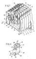
- the figure 1 illustrates a set of six juxtaposed junction blocks 1 to 6 according to the invention.
- Each terminal block comprises an insulating housing 10 in which is disposed an interconnection piece 11 of conductive material.
- the interconnection piece 11 is then equipped with various connection accessories such as for example but not exclusively a spring 12 for connecting an electric cable, a lyre 13 for connecting an interconnection comb 14.
- connection accessories such as for example but not exclusively a spring 12 for connecting an electric cable, a lyre 13 for connecting an interconnection comb 14.
- the interconnection piece 11 could be equipped with any other interconnection accessory such as, for example, screw connection files, insulation displacement connection systems, connector plug connection means or any other combination of these accessories.
- the insulating housing 10 has at least one housing 15 for receiving a plug-in connector 16, as is apparent from FIG. figure 1 .
- the interconnection piece 11 is then equipped with a male or female connection device 17 intended to cooperate with the plug connector 16.
- the connection device 16 is made in the form of a pin D axis corresponding to the direction of insertion of the connector on the block 1.
- the connection device 17 of the terminal block could also be constituted by a female device for, for example, to receive a pin connector.
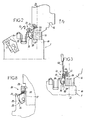
- the terminal block has locking means 20 of the connector 16 on the housing 10.
- the locking means 20 comprise a locking arm 21 which is integral with the housing 10 and which is fitted on the housing so as to be able to oscillate about an axis of rotation ⁇ between a position of erase E, more particularly illustrated in figure 2 , and a locking position V, as illustrated in FIG. figure 3 .
- the axis of rotation ⁇ is preferably substantially perpendicular to the insertion direction D.
- the arm 21 has a substantially parallelepipedal overall shape elongate axis d.
- the locking arm 21 then carries, at one of its so-called hooking ends 22, a hooking element 23 intended to cooperate with a complementary fastening element 24 of the connector 16.
- the fastening element 23 is constituted by a finger intended to bear, in the locking position, on a stop 25 defined by an edge of a cavity 24 which is arranged in the connector and which forms the element of complementary hanging of the finger 23.
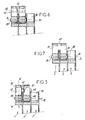
- the arm 21 has, moreover, at its end 27 opposite the attachment end 22, hinge means 28 on the housing 10.
- the hinge means 28 can be made anyway appropriate and, according to the example shown, they are constituted by two pivots 29 of axis ⁇ each arranged on a side face of the arm 21 and intended to engage in a complementary housing 32 offered by the housing 10, as is illustrated at figure 5 .
- the arm 21 is then fitted on the housing 10 in a housing 30 arranged near the housing 15 for receiving the connector 16.
- junction block 1 thus constituted is implemented in the following manner.
- the arm 21 Before placing the connector 16, the arm 21 is placed in the erasing position E as illustrated in FIG. figure 2 .
- the connector 16 can be freely inserted or removed from the housing 15 by a translation movement parallel to the insertion direction D.
- the arm 21 is moved in the direction of the arrow F1 to the locking position V in which the finger 23 is engaged in the housing 24 of the connector 16 to bear against the abutment 25 and thus oppose a removing the connector 16 in the direction of the arrow F2, as illustrated in FIG. figure 3 .
- the locking means 20 further comprise locking means 35 of the arm in the locking position V.
- the locking means 35 comprise a stop 36 arranged in the bottom of the housing 30 in which the arm 21 is mounted.
- the abutment 36 is then intended to provide a support in the locking position of the arm 21, a heel 37 of the hinge end 27 of the arm 21.
- the engagement of the heel 37 on the abutment 36 blocks the movements of the arm and then prevents a return of the arm 21 in the erasing position.
- the locking position V corresponds to a stable position of the arm 21.
- the heel 37 is situated at the opposite end along a diagonal of the fastening element 23.
- the heel 36 is opposite the housing 15 with respect to the hinge axis ⁇ of the arm 21.
- the bottom of the mounting housing of the arm 21 is adapted to oppose the passage of the arm 21 in the locking position. The positions erasure and locking then correspond to two stable states of the arm 21.
- the arm 21 comprises, preferably but not strictly necessary, at its end 22, a cavity 39 for receiving a control member. maneuver.
- the cavity 39 is shaped to receive the end of the screwdriver blade 40 which allows to have a leverage to unlock the arm 21 of its locking position.
- the arm 21 further comprises connecting means 41 with the locking arm 21 'of an adjacent junction block 2.
- This advantageous arrangement of the invention makes it possible to ensure concordance of positions between the locking arms 21, 21 'of the adjacent terminal blocks 1, 2.
- the connecting means 41 are made in the form, on the one hand, of a post 42 arranged in a lateral face of the locking arm 21 and, on the other hand, of a mortise 43, corresponding to the post 42, arranged in the opposite lateral face of the locking arm 21.
- the pin 42 of the connecting arm 21 engages in the corresponding mortise 43 of the adjacent locking arm 21 'during the juxtaposition of the terminal blocks 1 and 2 l one next to the other.
- the connecting means can be made in any other suitable form.
- the figure 6 illustrates another embodiment of the invention according to which the connecting means 40, between the various locking arms 21, are constituted by a through bore 45 arranged in each arm and allowing the establishment of a connecting rod 46 extending between the different locking arms 21, 21 'to be connected.
- the connecting means 40 between the adjacent locking arms 21, 21 'are removable.
- this connection is not necessarily removable.
- the connecting means 40 are formed by a connecting segment 47 connecting the two connecting arms 21.
- the two arms 21, 21 'then form a one-piece assembly, so that it is not possible to separate them.
- the locking means of the movement of the locking arm 21 comprise only the stop 36 intended to cooperate with the post 37 of the arm 21.
- the locking means 20 can be made under another form.
- the figure 8 illustrates an alternative embodiment in which the abutment 36 and the heel 37 are completed by a rack 51 arranged on the housing 10, the rack is then intended to cooperate with at least and, according to the illustrated example, several teeth 52 arranged on the arm 21.
- the friction and the engagement of the teeth 52, on the rack 51, then slow down the movements of the arm 21 and thus make it possible to reinforce its locking in the locked position in particular.
- the rack 51 and the teeth 52 could be implemented alone as locking means 20 without adding the blocking provided by the abutment 36 and the heel 37.
Description
La présente invention concerne le domaine technique des blocs de jonction ou d'interconnexion, modulaires ou non, utilisés pour l'alimentation et le contrôle d'installations électriques.The present invention relates to the technical field of terminal blocks or interconnection, modular or not, used for the supply and control of electrical installations.
Dans le domaine ci-dessus, l'invention concerne plus particulièrement les blocs de jonction destinés à recevoir un ou plusieurs connecteurs enfichables.In the above field, the invention relates more particularly to terminal blocks intended to receive one or more plug-in connectors.
De tels blocs de jonction comprennent généralement un boîtier isolant dans lequel est aménagé au moins un logement de réception d'un connecteur enfichable.Such terminal blocks generally comprise an insulating housing in which is arranged at least one receiving housing of a plug connector.
Afin d'éviter une désolidarisation intempestive du bloc de jonction et du connecteur sous l'effet par exemple de vibrations ou encore des tractions exercées sur les conducteurs raccordés au connecteur, il a été proposé de mettre en oeuvre des moyens de verrouillage du connecteur sur le bloc de jonction.In order to avoid an inadvertent disconnection of the terminal block and the connector under the effect for example of vibrations or of the pulls exerted on the conductors connected to the connector, it has been proposed to use locking means of the connector on the connector. terminal block.
Ainsi, il a été proposé d'aménager, au niveau de l'extrémité du connecteur destiné à venir s'engager dans le logement de réception, une butée destinée à coopérer avec un évidement complémentaire du logement. La butée et son évidement complémentaire permettent effectivement d'assurer un verrouillage du connecteur sur le boîtier mais présente toutefois l'inconvénient de rendre particulièrement difficile le retrait du connecteur une fois ce dernier raccordé au bloc de jonction. En effet, soit la butée et son évidement complémentaire sont conçus de manière à ne pas offrir une résistance trop importante au retrait du connecteur, auquel cas la fonction de verrouillage n'est pas convenablement assurée, soit, au contraire, la butée et son évidement complémentaire sont conçus pour offrir une grande résistance au retrait du connecteur auquel cas la fonction de verrouillage est parfaitement assurée mais il est quasiment impossible de retirer le connecteur sans endommager le bloc de jonction ou le connecteur lui-même.Thus, it has been proposed to arrange, at the end of the connector intended to engage in the receiving housing, a stop for cooperating with a complementary recess of the housing. The abutment and its complementary recess effectively make it possible to lock the connector on the housing, but nevertheless has the drawback of making it particularly difficult to remove the connector once the latter is connected to the terminal block. Indeed, the abutment and its complementary recess are designed so as not to offer too much resistance to the withdrawal of the connector, in which case the locking function is not properly ensured, is, on the contrary, the stop and its recess are designed to provide high resistance to removal of the connector in which case the locking function is perfectly ensured but it is almost impossible to remove the connector without damaging the terminal block or the connector itself.
Afin de remédier à cet inconvénient, il a été proposé de mettre en oeuvre, en tant que moyens de verrouillage du connecteur sur le bloc de jonction, une patte d'accrochage rapportée sur le connecteur et destinée à venir s'engager sur une butée complémentaire du bloc de jonction. Une telle patte donne satisfaction dans sa fonction de verrouillage du connecteur sur le bloc de jonction et permet, par ailleurs, un déverrouillage aisé lorsqu'il est nécessaire de désolidariser le connecteur du bloc de jonction.In order to remedy this disadvantage, it has been proposed to implement, as locking means of the connector on the terminal block, a hooking tab attached to the connector and intended to engage a complementary abutment. of the terminal block. Such a lug is satisfactory in its locking function of the connector on the terminal block and allows, moreover, easy unlocking when it is necessary to separate the connector of the terminal block.
Toutefois, la mise en oeuvre d'une telle patte d'accrochage rapportée, présente l'inconvénient d'augmenter l'encombrement du connecteur. De plus, la patte rapportée vient s'accrocher sur une butée aménagée dans une paroi latérale du bloc de jonction de sorte qu'il n'est pas possible d'utiliser une telle patte d'accrochage pour le verrouillage d'un connecteur enfiché dans une région centrale du bloc de jonction.However, the implementation of such an attachment tab reported, has the disadvantage of increasing the size of the connector. In addition, the insert tab is hooked on a stop arranged in a side wall of the terminal block so that it is not possible to use such a bracket for locking a connector plugged into a central region of the terminal block.
Par ailleurs, dans la mesure où la patte d'accrochage est rapportée sur le connecteur, il est nécessaire, lors de la mise en oeuvre du connecteur, de prévoir cette patte d'accrochage qui vient augmenter le nombre de composants nécessaires à la réalisation d'un ensemble de jonction et de raccordement. De plus, la patte d'accrochage présente un encombrement qui rend difficile son utilisation dans un environnement exigu.Furthermore, insofar as the attachment tab is attached to the connector, it is necessary, during the implementation of the connector, to provide this latching lug which increases the number of components necessary for the production of the connector. a junction and connection assembly. In addition, the attachment tab has a size that makes it difficult to use in a small environment.
D'autre part, des bras de verrouillage d'un connecteur, solidaires du boîtier de réception du connecteur et qui coopèrent avec des crans ménagés sur le connecteur, sont connus du brevet
Il apparaît donc le besoin de disposer de nouveaux moyens de verrouillage qui obviennent aux inconvénients ci-dessus et qui, notamment, soient simples d'utilisation et présentent un encombrement réduit, tout en assurant un verrouillage efficace du connecteur sur le bloc de jonction et qui ne présentent aucun risque de perte.It therefore appears to be necessary to have new locking means that obviate the above drawbacks and which, in particular, are simple to use and have a small footprint, while ensuring effective locking of the connector on the terminal block and which have no risk of loss.
Afin d'atteindre ces objectifs, l'invention concerne un bloc de jonction qui comprend :
- un boîtier isolant dans lequel est aménagé au moins un logement de réception d'un connecteur enfichable dans le logement selon une direction (D),
- et des moyens de verrouillage du connecteur sur le boîtier.
- an insulating housing in which is arranged at least one receiving housing of a plug-in connector in the housing in a direction (D),
- and locking means of the connector on the housing.
Selon l'invention, les moyens de verrouillage comprennent :
- au moins un bras de verrouillage qui est :
- * solidaire du boîtier,
- * oscillant autour d'un axe de rotation (Δ), entre une position d'effacement et une position de verrouillage,
- * équipé un élément d'accrochage destiné à coopérer en position de verrouillage avec un élément d'accrochage complémentaire du connecteur,
- et des moyens de blocage du bras en position de verrouillage.
- at least one locking arm which is:
- * integral with the housing,
- * oscillating about an axis of rotation (Δ), between an erasing position and a locking position,
- * equipped with a hooking element intended to cooperate in the locking position with a complementary coupling element of the connector,
- and means for locking the arm in the locking position.
Ainsi, dans la mesure où le bras de verrouillage est solidaire du bloc de jonction, il n'est pas possible de le perdre. De plus, cette présence à demeure évite tout risque d'oubli lors du montage et de l'assemblage d'un ensemble de jonction et de connexion mettant en oeuvre un ou plusieurs blocs de jonction selon l'invention.Thus, insofar as the locking arm is integral with the terminal block, it is not possible to lose it. Moreover, this presence at home avoids any risk of forgetting when assembling and assembling a junction and connection assembly using one or more terminal blocks according to the invention.
Selon une caractéristique de l'invention, afin de réduire au maximum l'encombrement du bloc de jonction et l'espace dédié, sur ce dernier, aux moyens de verrouillage, l'axe de rotation Δ du bras est sensiblement perpendiculaire à la direction D d'enfichage du connecteur.According to one characteristic of the invention, in order to reduce as much as possible the size of the terminal block and the dedicated space, on the latter, with the locking means, the axis of rotation Δ of the arm is substantially perpendicular to the direction D plugging in the connector.
Le bras de verrouillage peut être réalisé de toute manière appropriée et, selon une caractéristique de l'invention, le bras de verrouillage présente une forme allongée d'axe d et porte, à une extrémité, l'élément d'accrochage, et à l'extrémité opposée, des moyens d'articulation sur le boîtier.The locking arm may be made in any suitable manner and, according to a feature of the invention, the locking arm has an elongated shape of axis d and carries, at one end, the fastening element, and at opposite end, hinge means on the housing.
Les moyens d'articulation peuvent alors être réalisés de toute manière appropriée comme par exemple sous la forme d'un palier destiné à coopérer avec un axe porté par le boîtier du bloc de jonction. De même, les moyens d'interconnexion peuvent aussi être réalisés sous la forme d'un axe solidaire du bras de verrouillage et destiné à venir s'engager dans un palier aménagé sur le boîtier isolant du bloc de jonction.The hinge means can then be made in any appropriate manner, for example in the form of a bearing intended to cooperate with an axis carried by the terminal block housing. Similarly, the interconnection means may also be in the form of a fixed axis of the locking arm and intended to engage in a bearing arranged on the insulating housing of the terminal block.
Selon une forme préférée de réalisation de l'invention, les moyens de blocage du bras de verrouillage comprennent une butée aménagée sur le boîtier pour offrir un appui au bras en position de verrouillage et faire obstacle au passage du bras en position d'effacement à partir de cette position de verrouillage.According to a preferred embodiment of the invention, the locking means of the locking arm comprise a stop provided on the housing to provide support for the arm in the locking position and to prevent the passage of the arm in the erasing position from of this locking position.
Selon une caractéristique de l'invention, le bras de verrouillage présente alors, au niveau de son extrémité d'articulation et à l'opposé de l'élément d'accrochage, un talon destiné à venir en appui sur la butée du boîtier lorsque le bras est en position de verrouillage.According to a feature of the invention, the locking arm then has, at its hinge end and opposite the fastening element, a bead intended to bear against the abutment of the housing when the arm is in the locked position.
Afin d'offrir une grande résistance au déverrouillage notamment sous l'effet d'efforts appliqués au niveau de l'élément d'accrochage par le connecteur verrouillé, le talon est situé à l'opposé du logement de réception du connecteur par rapport à l'axe Δ de rotation du bras.In order to offer a high resistance to unlocking in particular under the effect of forces applied to the fastening element by the locked connector, the heel is located opposite the receiving housing of the connector relative to the Δ axis of rotation of the arm.
Selon une autre caractéristique de l'invention, les moyens de blocage comprennent une crémaillère aménagée sur le boîtier et au moins une dent portée par le bras de verrouillage et destinée à coopérer avec la crémaillère pour freiner le mouvement du bras de verrouillage entre sa position d'effacement et sa position de verrouillage, et inversement. De manière préférée mais non strictement nécessaire, la crémaillère est utilisée en association avec la butée de blocage aménagée sur le boîtier.According to another characteristic of the invention, the locking means comprise a rack arranged on the housing and at least one tooth carried by the locking arm and intended to cooperate with the rack to slow the movement of the locking arm between its position. erasure and its locking position, and vice versa. So preferred but not strictly necessary, the rack is used in combination with the stopper on the housing.
Conformément à l'invention, l'élément d'accrochage du bras de verrouillage peut être réalisé de toute manière appropriée telle que par exemple sous la forme d'un élément d'accrochage mâle ou femelle destiné à coopérer avec un élément de forme complémentaire aménagé sur le connecteur. Selon une forme préférée de réalisation, l'élément d'accrochage est constitué par un doigt destiné à coopérer avec une butée offerte par le connecteur pour faire obstacle au retrait du connecteur hors du logement de réception. De manière préférée mais non strictement nécessaire, la butée du connecteur est constituée par le bord d'une cavité de réception du doigt d'accrochage aménagé dans la paroi externe du connecteur.According to the invention, the locking element of the locking arm can be made in any appropriate manner such as for example in the form of a male or female coupling element intended to cooperate with a complementary shaped element arranged on the connector. According to a preferred embodiment, the hooking element is constituted by a finger intended to cooperate with a stop provided by the connector to prevent removal of the connector from the receiving housing. In a preferred but not strictly necessary manner, the abutment of the connector is formed by the edge of a receiving cavity of the latching finger arranged in the outer wall of the connector.
Par ailleurs, selon une forme préférée, mais non strictement nécessaire, de réalisation, le bras présente, afin de faciliter sa manipulation entre la position de verrouillage et la position d'effacement et inversement, une cavité de réception d'un organe de manoeuvre extérieur. De manière préférée, cette cavité de manoeuvre est aménagée au niveau de l'extrémité du bras opposée à l'extrémité d'articulation sur le boîtier et présente une forme adaptée à la réception de l'extrémité d'une lame de tournevis. Ainsi, lorsqu'il est nécessaire d'effectuer un déverrouillage du bras, il est possible de disposer, en introduisant la lame d'un tournevis dans la cavité de manoeuvre, d'un bras de levier important.Furthermore, according to a preferred embodiment, but not strictly necessary, the arm has, in order to facilitate its manipulation between the locking position and the erasing position and vice versa, a receiving cavity of an external actuator . Preferably, this operating cavity is arranged at the end of the arm opposite to the hinge end on the housing and has a shape adapted to receive the end of a screwdriver blade. Thus, when it is necessary to unlock the arm, it is possible to have, by introducing the blade of a screwdriver into the operating cavity, a large lever arm.
Selon une autre caractéristique de l'invention, le bras de verrouillage présente des moyens de liaison destinés à relier le bras de verrouillage avec un autre bras de verrouillage d'un bloc de liaison adjacent.According to another characteristic of the invention, the locking arm has connecting means for connecting the locking arm with another locking arm of an adjacent link block.
Les moyens de liaison peuvent être réalisés de toute façon appropriée et, selon une forme de réalisation préférée mais non strictement nécessaire de l'invention, les moyens de liaison comprennent un tenon, aménagé sur une face latérale du bras, et une mortaise de forme complémentaire à celle du tenon, aménagé sur la face latérale opposée du bras de verrouillage.The connecting means may be made in any suitable manner and, according to a preferred but not strictly necessary embodiment of the invention, the connecting means comprise a tenon, arranged on a lateral face of the arm, and a mortise of complementary shape. to that of the tenon, arranged on the opposite lateral face of the locking arm.
L'invention concerne également un ensemble d'au moins deux blocs de jonction, selon l'invention, juxtaposés. Cet ensemble est caractérisé en ce que les bras de verrouillage d'au moins deux blocs de jonction adjacents sont liés l'un à l'autre.The invention also relates to an assembly of at least two junction blocks, according to the invention, juxtaposed. This assembly is characterized in that the locking arms of at least two adjacent terminal blocks are connected to each other.
Cette liaison peut alors résulter de la mise en oeuvre des moyens de liaison tels qu'évoqués ci-dessus et se trouve donc démontable. La liaison des bras de verrouillage de blocs adjacents peut aussi résulter de la fabrication en une seule pièce des bras de verrouillage des deux blocs adjacents. Il peut également être envisagé de réaliser, en une seule pièce, les bras de verrouillage de plus de deux blocs. Bien entendu, cette forme de réalisation n'exclut pas la possibilité de faire intervenir des moyens de liaison démontables, aménagés au niveau des faces latérales de la pièce constitutive des bras de liaison juxtaposés.This connection can then result from the implementation of the connection means as mentioned above and is therefore removable. The connection of the adjacent block locking arms may also result from the one-piece manufacture of the locking arms of the two adjacent blocks. It can also be envisaged to produce, in one piece, the locking arms of more than two blocks. Of course, this embodiment does not exclude the possibility of involving removable connecting means, arranged at the side faces of the component part juxtaposed connecting arms.
Diverses autres caractéristiques de l'invention ressortent de la description ci-dessus effectuée en référence aux dessins annexés qui illustrent différentes formes de réalisation non limitatives d'un ou plusieurs blocs de jonction selon l'invention.
- La
figure 1 est une perspective d'un ensemble de blocs de jonction selon l'invention juxtaposés. - La
figure 2 est une vue en élévation d'un bloc de jonction selon l'invention dont le bras de verrouillage est en position d'effacement. - La
figure 3 est une vue analogue à lafigure 2 montrant le bras du bloc de jonction en position de verrouillage. - La
figure 4 est une perspective d'un bras de verrouillage pour un b!oc de jonction se!on l'invention. - La
figure 5 est une coupe selon le plan V-V de lafigure 1 . - Les
figures 6 et 7 sont des coupes analogues à lafigure 5 montrant d'autre forme de réalisation de blocs de jonction selon l'invention. - La
figure 8 est une vue analogue à lafigure 3 montrant une autre forme de réalisation des moyens de verrouillage d'un bloc de jonction selon l'invention.
- The
figure 1 is a perspective of a set of terminal blocks according to the invention juxtaposed. - The
figure 2 is an elevational view of a terminal block according to the invention in which the locking arm is in the erasing position. - The
figure 3 is a view similar to thefigure 2 showing the terminal block arm in the lock position. - The
figure 4 is a perspective of a locking arm for a joining junction according to the invention. - The
figure 5 is a section along the VV plane of thefigure 1 . - The
Figures 6 and 7 are similar cuts to thefigure 5 showing another embodiment of terminal blocks according to the invention. - The
figure 8 is a view similar to thefigure 3 showing another embodiment of the locking means of a terminal block according to the invention.
La
Chaque bloc de jonction comprend un boîtier isolant 10 dans lequel est disposée une pièce d'interconnexion 11 en matériau conducteur. La pièce d'interconnexion 11 est alors équipée de différents accessoires de raccordement tels que par exemple mais non exclusivement un ressort 12 de raccordement d'un câble électrique, une lyre 13 pour le raccordement d'un peigne d'interconnexion 14. Bien entendu, la pièce d'interconnexion 11 pourrait être équipée de tout autre accessoire d'interconnexion tel que par exemple des fichiers de raccordement à vis, des systèmes de raccordement autodénudants, des moyens de raccordement de connecteurs enfichables ou encore toute autre combinaison de ces différents accessoires.Each terminal block comprises an insulating
Conformément à une caractéristique essentielle de l'invention, le boîtier isolant 10 présente au moins un logement 15 de réception d'un connecteur enfichable 16, comme cela ressort de la
Afin de garantir une résistance à l'arrachage et une bonne tenue aux vibrations du raccordement du connecteur 16 sur le boîtier isolant 10, le bloc de jonction présente des moyens de verrouillage 20 du connecteur 16 sur le boîtier 10.In order to guarantee resistance to tearing and good vibration resistance of the connection of the
Selon l'invention, les moyens de verrouillage 20 comprennent un bras de verrouillage 21 qui est solidaire du boîtier 10 et qui est adapté, sur le boîtier, de manière à pouvoir osciller autour d'un axe de rotation Δ, entre une position d'effacement E, plus particulièrement illustrée à la
Selon la forme de réalisation préférée et comme le montre la
Le bras 21 comporte, par ailleurs, au niveau de son extrémité 27 opposée à l'extrémité d'accrochage 22, des moyens d'articulation 28 sur le boîtier 10. Les moyens d'articulation 28 peuvent être réalisés de toute façon appropriée et, selon l'exemple illustré, ils sont constitués par deux pivots 29 d'axe Δ aménagés chacun sur une face latérale du bras 21 et destinés à venir s'engager dans un logement complémentaire 32 offert par le boîtier 10, comme cela est illustré à la
Le bloc de jonction 1 ainsi constitué est mis en oeuvre de la manière suivante.The junction block 1 thus constituted is implemented in the following manner.
Avant mise en place du connecteur 16, le bras 21 est placé en position d'effacement E telle qu'illustrée à la
Afin d'éviter un déverrouillage intempestif du bras 21, les moyens de verrouillage 20 comprennent en outre des moyens de blocage 35 du bras en position de verrouillage V.In order to avoid inadvertent unlocking of the
Selon l'exemple illustré, les moyens de verrouillage 35 comprennent une butée 36 aménagée dans le fond du logement 30 dans lequel le bras 21 est monté. La butée 36 est alors destinée à offrir un appui en position de verrouillage du bras 21, à un talon 37 de l'extrémité d'articulation 27 du bras 21. L'engagement du talon 37 sur la butée 36 bloque les mouvements du bras et empêche alors un retour du bras 21 en position d'effacement. Ainsi, la position de verrouillage V correspond à une position stable du bras 21.According to the illustrated example, the locking means 35 comprise a
Afin d'offrir la meilleure résistance possible aux efforts de traction exercés dans le sens de la flèche F2 sur le connecteur 16, le talon 37 est situé à l'opposé selon une diagonale de l'élément d'accrochage 23. Dans le même sens, le talon 36 se trouve à l'opposé du logement 15 par rapport à l'axe d'articulation Δ du bras 21. Dans le même sens, afin d'éviter un passage intempestif du bras 21 en position de verrouillage V à partir de la position d'effacement E, le fond du logement du montage du bras 21 est adapté pour s'opposer au passage du bras 21 en position de verrouillage. Les positions d'effacement et de verrouillage correspondent alors à deux états stables du bras 21.In order to offer the best possible resistance to the tensile forces exerted in the direction of the arrow F2 on the
Afin de faciliter la manoeuvre du bras 21 entre ses positions d'effacement E et de verrouillage V, le bras 21 comprend, de manière préférée mais non strictement nécessaire, au niveau de son extrémité 22, une cavité 39 de réception d'un organe de manoeuvre.In order to facilitate the maneuvering of the
Selon l'exemple illustré, la cavité 39 est conformée pour recevoir l'extrémité de la lame de tournevis 40 qui permet de disposer d'un effet de levier pour débloquer le bras 21 de sa position de verrouillage.In the example shown, the
Selon une forme de réalisation préférée mais non strictement nécessaire, le bras 21 comprend en outre des moyens de liaison 41 avec le bras de verrouillage 21' d'un bloc de jonction adjacent 2. Cette disposition avantageuse de l'invention permet d'assurer une concordance de positions entre les bras de verrouillage 21, 21' des blocs de jonction adjacents 1, 2.According to a preferred embodiment but not strictly necessary, the
Selon l'exemple illustré à la
Toutefois, conformément à l'invention, les moyens de liaison peuvent être réalisés sous une toute autre forme appropriée.However, according to the invention, the connecting means can be made in any other suitable form.
Ainsi, la
Selon les exemples décrits précédemment, les moyens de liaison 40, entre les bras de verrouillage adjacents 21, 21' sont démontables. Toutefois, selon l'invention, cette liaison n'est pas nécessairement démontable.According to the examples described above, the connecting
Ainsi, selon l'exemple illustré à la
Selon les exemples décrits précédemment, les moyens de blocage du mouvement du bras de verrouillage 21 comprennent uniquement la butée 36 destinée à coopérer avec le tenon 37 du bras 21. Toutefois, conformément à l'invention, les moyens de blocage 20 peuvent être réalisés sous une autre forme.According to the examples described above, the locking means of the movement of the locking
Ainsi, la
Bien entendu, selon l'invention, la crémaillère 51 et les dents 52 pourraient être mises en oeuvre seules en tant que moyens de blocage 20 sans adjonction du blocage assuré par la butée 36 et le talon 37.Of course, according to the invention, the rack 51 and the
L'invention n'est pas limitée aux exemples décrits ci-dessus et différentes modifications peuvent y être apportées sans sortir de son cadre.The invention is not limited to the examples described above and various modifications can be made without departing from its scope.
Claims (10)
- A terminal block of the type comprising:- an insulating casing (10) in which is made at least one housing (15) for receiving a connector (16), pluggable into the housing (15) along a direction (D),- means (20) for locking the connector on the casing,
the locking means comprising:- at least one locking arm (21), which is:* firmly attached to the casing (10),* oscillating around an axis of rotation (Δ), between a withdrawal position (E) and a locking position (V),* equipped with an attachment element intended to co-operate in the locking position with a mating attachment element of the connector,- means (35) for blocking the arm in the locking position (V),
the blocking means (35) comprising an abutment (36) made on the casing in order to provide support to the arm (21) in the locking position, and to hinder the passing of the arm into the withdrawal position,
the locking arm (21) having an elongated shape with an axis (d) and bears at one end (22), the attachment element (23) and, at the opposite end, jointing means (28) on the casing (10), the terminal block being characterized in that the locking arm (21) has, at its jointing end (27) and opposite to the attachment element (23), a heel (37) intended to bear upon the abutment (36) of the casing, in the locking position (V) of the arm (21). - The terminal block according to claim 1, characterized in that the axis of rotation (Δ) of the arm is substantially perpendicular to the direction (D) for plugging in the connector.
- The terminal block according to one of claims 1 or 2, characterized in that the heel (37) is located opposite the housing (15) with respect to the axis of rotation (Δ) of the arm (21).
- The terminal block according to one of claims 1 to 3, characterized in that the blocking means (35) comprise:- a rack (S1) made on the casing (10),- and at least one tooth (S2) borne by the locking arm (21) and intended to co-operate with the rack (51) so as to slow down the movement of the arm.
- The terminal block according to one of claims 1 to 4, characterized in that the element for attaching the arm (21) is formed by a finger (23) intended to co-operate with an abutment (25), provided by the connector (16), for hindering the removal of the connector (16) out of the receiving housing (15).
- The terminal block according to one of claims 1 to 5, characterized in that the arm (21) has a cavity (39) for receiving a maneuvering member.
- The terminal block according to claim 6, characterized in that the cavity (39) is conformed in order to receive the end of a screwdriver blade (40).
- The terminal block according to one of claims 1 to 7, characterized in that the locking arm (21) has connecting means (41) intended to connect the locking arm (21) with another locking arm (21') of an adjacent connecting block.
- The terminal block according to claim 8, characterized in that the connecting means comprise a tenon (42) made on a side face of the arm (21) and a mortise (43) with a shape mating that of the tenon, made in the side face opposite to the locking arm (21).
- An assembly of at least two juxtaposed terminal blocks (1, 2, 3, 4, 5, 6), according to one of claims 1 to 9, characterized in that the locking arms (21, 21') of at least two adjacent terminal blocks (1, 22) are connected to each other.
Applications Claiming Priority (2)
| Application Number | Priority Date | Filing Date | Title |
|---|---|---|---|
| FR0109939 | 2001-07-25 | ||
| FR0109939A FR2828018B1 (en) | 2001-07-25 | 2001-07-25 | JUNCTION BLOCK WITH LOCKING ARM FOR CONNECTABLE CONNECTOR |
Publications (2)
| Publication Number | Publication Date |
|---|---|
| EP1286427A1 EP1286427A1 (en) | 2003-02-26 |
| EP1286427B1 true EP1286427B1 (en) | 2011-06-29 |
Family
ID=8865888
Family Applications (1)
| Application Number | Title | Priority Date | Filing Date |
|---|---|---|---|
| EP02356125A Expired - Lifetime EP1286427B1 (en) | 2001-07-25 | 2002-07-03 | Terminal-block with lock-arm for plug connector |
Country Status (3)
| Country | Link |
|---|---|
| US (1) | US6733330B2 (en) |
| EP (1) | EP1286427B1 (en) |
| FR (1) | FR2828018B1 (en) |
Families Citing this family (4)
| Publication number | Priority date | Publication date | Assignee | Title |
|---|---|---|---|---|
| DE102005040657A1 (en) * | 2005-08-26 | 2007-03-15 | Phoenix Contact Gmbh & Co. Kg | Electrical connection terminal |
| US7462063B1 (en) | 2007-07-31 | 2008-12-09 | Phoenix Contact Development & Manufacturing, Inc. | Modular terminal block |
| DE102012010391A1 (en) | 2011-06-17 | 2012-12-20 | Phoenix Contact Gmbh & Co. Kg | Electrical connection module |
| PL3054533T3 (en) * | 2015-02-05 | 2020-06-29 | Morsettitalia S.P.A. | Base terminal block and auxiliary terminal block for switchboards and two-tier terminal block assembly comprising base terminal block and auxiliary terminal block |
Citations (2)
| Publication number | Priority date | Publication date | Assignee | Title |
|---|---|---|---|---|
| BE847193A (en) * | 1975-10-13 | 1977-01-31 | ASSEMBLY MECHANISM FOR MALES AND FEMALE CONNECTORS, | |
| GB2260654A (en) * | 1991-10-04 | 1993-04-21 | Unisys Corp | Electrical connector cover |
Family Cites Families (4)
| Publication number | Priority date | Publication date | Assignee | Title |
|---|---|---|---|---|
| FR2031698A5 (en) * | 1969-02-04 | 1970-11-20 | Comp Generale Electricite | |
| CH652242A5 (en) * | 1980-12-02 | 1985-10-31 | Sprecher & Schuh Ag | Switchable terminal block for switching installations |
| DE4312667C2 (en) * | 1993-04-19 | 1995-06-08 | Weidmueller Interface | Test plug for terminal blocks |
| DE29908612U1 (en) * | 1999-05-14 | 1999-07-15 | Weidmueller Interface | Terminal block |
-
2001
- 2001-07-25 FR FR0109939A patent/FR2828018B1/en not_active Expired - Fee Related
-
2002
- 2002-07-03 EP EP02356125A patent/EP1286427B1/en not_active Expired - Lifetime
- 2002-07-11 US US10/192,644 patent/US6733330B2/en not_active Expired - Fee Related
Patent Citations (2)
| Publication number | Priority date | Publication date | Assignee | Title |
|---|---|---|---|---|
| BE847193A (en) * | 1975-10-13 | 1977-01-31 | ASSEMBLY MECHANISM FOR MALES AND FEMALE CONNECTORS, | |
| GB2260654A (en) * | 1991-10-04 | 1993-04-21 | Unisys Corp | Electrical connector cover |
Also Published As
| Publication number | Publication date |
|---|---|
| US6733330B2 (en) | 2004-05-11 |
| US20030022551A1 (en) | 2003-01-30 |
| FR2828018B1 (en) | 2006-12-22 |
| FR2828018A1 (en) | 2003-01-31 |
| EP1286427A1 (en) | 2003-02-26 |
Similar Documents
| Publication | Publication Date | Title |
|---|---|---|
| EP2324534B1 (en) | Connection device between an electrical cable and a conducting structure, especially for a current return circuit | |
| EP0371835B1 (en) | Device forming an electrical connector | |
| EP3651275B1 (en) | Housing for connector provided with an improved cable terminal position assurance (tpa) and method of mounting a cable terminal in a connector | |
| FR2720197A1 (en) | Connector for electric cable. | |
| EP2803543A2 (en) | Hydraulic and/or electric connection interface for windscreen-wiper blade | |
| EP1286427B1 (en) | Terminal-block with lock-arm for plug connector | |
| EP3089295B1 (en) | Electrical interconnection device for an equipotential connection between a cable tray piece and an electrical cable piece. | |
| WO2008099093A2 (en) | Connector with simplified mounting for a multiple conductor cable | |
| EP0744088A1 (en) | Electric plug of the british type | |
| EP1928058B1 (en) | Automatic electrical connection terminal | |
| EP2843766B1 (en) | Electrical device including an electric circuit printed on a substrate and an electric connection terminal | |
| FR2688350A1 (en) | Electrical connection device and, more particularly, a charging (load) connector | |
| EP2068411A1 (en) | Embedded electrical appliance with quick connection | |
| EP0884806A2 (en) | Electrical connector with improved contact security | |
| FR2778275A1 (en) | LOCKED ELECTRICAL CONNECTION DEVICE | |
| EP2746521B1 (en) | Supporting plate of a winding tube of a roller shutter | |
| FR3028356A1 (en) | ELECTRICAL CONNECTION TERMINAL WITH IMPERDABLE SCREW | |
| FR2655207A1 (en) | Electrical connector which includes improved terminal retention means | |
| WO2014096681A1 (en) | Equipment module and electrical connector of electrical equipment | |
| EP2936635A1 (en) | Electrical equipment module | |
| FR2800521A1 (en) | ELECTRICAL CONNECTOR WITH PADLOCK CONNECTION LOCK | |
| FR2915026A1 (en) | Tuning fork shaped flat cable connecting device for road vehicle, has closing elements allowing perforation of cable by spigots to establish electrical connection between conductors of cables and maintain cable clamped against base wall | |
| FR2946188A1 (en) | CONNECTING DEVICE | |
| FR3135839A1 (en) | Electrical terminal block provided with a male element and a female electrical connection element. | |
| EP2367238B1 (en) | Low voltage connector for communication system |
Legal Events
| Date | Code | Title | Description |
|---|---|---|---|
| PUAI | Public reference made under article 153(3) epc to a published international application that has entered the european phase |
Free format text: ORIGINAL CODE: 0009012 |
|
| AK | Designated contracting states |
Kind code of ref document: A1 Designated state(s): AT BE BG CH CY CZ DE DK EE ES FI FR GB GR IE IT LI LU MC NL PT SE SK TR |
|
| AX | Request for extension of the european patent |
Extension state: AL LT LV MK RO SI |
|
| 17P | Request for examination filed |
Effective date: 20030602 |
|
| AKX | Designation fees paid |
Designated state(s): BE DE ES GB IT |
|
| RAP1 | Party data changed (applicant data changed or rights of an application transferred) |
Owner name: ABB ENTRELEC |
|
| RAP1 | Party data changed (applicant data changed or rights of an application transferred) |
Owner name: ABB FRANCE |
|
| 17Q | First examination report despatched |
Effective date: 20100820 |
|
| GRAP | Despatch of communication of intention to grant a patent |
Free format text: ORIGINAL CODE: EPIDOSNIGR1 |
|
| GRAS | Grant fee paid |
Free format text: ORIGINAL CODE: EPIDOSNIGR3 |
|
| GRAA | (expected) grant |
Free format text: ORIGINAL CODE: 0009210 |
|
| AK | Designated contracting states |
Kind code of ref document: B1 Designated state(s): BE DE ES GB IT |
|
| REG | Reference to a national code |
Ref country code: GB Ref legal event code: FG4D Free format text: NOT ENGLISH |
|
| REG | Reference to a national code |
Ref country code: DE Ref legal event code: R096 Ref document number: 60240384 Country of ref document: DE Effective date: 20110818 |
|
| BERE | Be: lapsed |
Owner name: ABB FRANCE Effective date: 20110731 |
|
| PG25 | Lapsed in a contracting state [announced via postgrant information from national office to epo] |
Ref country code: BE Free format text: LAPSE BECAUSE OF NON-PAYMENT OF DUE FEES Effective date: 20110731 |
|
| PLBE | No opposition filed within time limit |
Free format text: ORIGINAL CODE: 0009261 |
|
| STAA | Information on the status of an ep patent application or granted ep patent |
Free format text: STATUS: NO OPPOSITION FILED WITHIN TIME LIMIT |
|
| GBPC | Gb: european patent ceased through non-payment of renewal fee |
Effective date: 20110929 |
|
| 26N | No opposition filed |
Effective date: 20120330 |
|
| REG | Reference to a national code |
Ref country code: DE Ref legal event code: R097 Ref document number: 60240384 Country of ref document: DE Effective date: 20120330 |
|
| PG25 | Lapsed in a contracting state [announced via postgrant information from national office to epo] |
Ref country code: GB Free format text: LAPSE BECAUSE OF NON-PAYMENT OF DUE FEES Effective date: 20110929 |
|
| PG25 | Lapsed in a contracting state [announced via postgrant information from national office to epo] |
Ref country code: ES Free format text: LAPSE BECAUSE OF FAILURE TO SUBMIT A TRANSLATION OF THE DESCRIPTION OR TO PAY THE FEE WITHIN THE PRESCRIBED TIME-LIMIT Effective date: 20111010 |
|
| PGFP | Annual fee paid to national office [announced via postgrant information from national office to epo] |
Ref country code: DE Payment date: 20130722 Year of fee payment: 12 |
|
| PGFP | Annual fee paid to national office [announced via postgrant information from national office to epo] |
Ref country code: IT Payment date: 20130730 Year of fee payment: 12 |
|
| REG | Reference to a national code |
Ref country code: DE Ref legal event code: R119 Ref document number: 60240384 Country of ref document: DE |
|
| PG25 | Lapsed in a contracting state [announced via postgrant information from national office to epo] |
Ref country code: DE Free format text: LAPSE BECAUSE OF NON-PAYMENT OF DUE FEES Effective date: 20150203 Ref country code: IT Free format text: LAPSE BECAUSE OF NON-PAYMENT OF DUE FEES Effective date: 20140703 |
|
| REG | Reference to a national code |
Ref country code: DE Ref legal event code: R119 Ref document number: 60240384 Country of ref document: DE Effective date: 20150203 |