EP2367238B1 - Low voltage connector for communication system - Google Patents
Low voltage connector for communication system Download PDFInfo
- Publication number
- EP2367238B1 EP2367238B1 EP11154502.6A EP11154502A EP2367238B1 EP 2367238 B1 EP2367238 B1 EP 2367238B1 EP 11154502 A EP11154502 A EP 11154502A EP 2367238 B1 EP2367238 B1 EP 2367238B1
- Authority
- EP
- European Patent Office
- Prior art keywords
- connector
- cable
- locking member
- opening
- wires
- Prior art date
- Legal status (The legal status is an assumption and is not a legal conclusion. Google has not performed a legal analysis and makes no representation as to the accuracy of the status listed.)
- Active
Links
- 238000004891 communication Methods 0.000 title claims description 5
- 238000006073 displacement reaction Methods 0.000 claims description 16
- 230000000295 complement effect Effects 0.000 claims description 14
- 238000009413 insulation Methods 0.000 claims description 13
- 239000002184 metal Substances 0.000 claims description 5
- 238000000034 method Methods 0.000 claims description 5
- 239000007769 metal material Substances 0.000 claims description 4
- 238000003780 insertion Methods 0.000 description 3
- 230000037431 insertion Effects 0.000 description 3
- 239000000463 material Substances 0.000 description 3
- 239000004020 conductor Substances 0.000 description 1
- 230000005489 elastic deformation Effects 0.000 description 1
- 239000002991 molded plastic Substances 0.000 description 1
- 230000037361 pathway Effects 0.000 description 1
- 239000004033 plastic Substances 0.000 description 1
- 238000011084 recovery Methods 0.000 description 1
Images


Classifications
-
- H—ELECTRICITY
- H01—ELECTRIC ELEMENTS
- H01R—ELECTRICALLY-CONDUCTIVE CONNECTIONS; STRUCTURAL ASSOCIATIONS OF A PLURALITY OF MUTUALLY-INSULATED ELECTRICAL CONNECTING ELEMENTS; COUPLING DEVICES; CURRENT COLLECTORS
- H01R13/00—Details of coupling devices of the kinds covered by groups H01R12/70 or H01R24/00 - H01R33/00
- H01R13/58—Means for relieving strain on wire connection, e.g. cord grip, for avoiding loosening of connections between wires and terminals within a coupling device terminating a cable
- H01R13/582—Means for relieving strain on wire connection, e.g. cord grip, for avoiding loosening of connections between wires and terminals within a coupling device terminating a cable the cable being clamped between assembled parts of the housing
- H01R13/5829—Means for relieving strain on wire connection, e.g. cord grip, for avoiding loosening of connections between wires and terminals within a coupling device terminating a cable the cable being clamped between assembled parts of the housing the clamping part being flexibly or hingedly connected to the housing
-
- H—ELECTRICITY
- H01—ELECTRIC ELEMENTS
- H01R—ELECTRICALLY-CONDUCTIVE CONNECTIONS; STRUCTURAL ASSOCIATIONS OF A PLURALITY OF MUTUALLY-INSULATED ELECTRICAL CONNECTING ELEMENTS; COUPLING DEVICES; CURRENT COLLECTORS
- H01R24/00—Two-part coupling devices, or either of their cooperating parts, characterised by their overall structure
- H01R24/60—Contacts spaced along planar side wall transverse to longitudinal axis of engagement
- H01R24/62—Sliding engagements with one side only, e.g. modular jack coupling devices
- H01R24/64—Sliding engagements with one side only, e.g. modular jack coupling devices for high frequency, e.g. RJ 45
-
- H—ELECTRICITY
- H01—ELECTRIC ELEMENTS
- H01R—ELECTRICALLY-CONDUCTIVE CONNECTIONS; STRUCTURAL ASSOCIATIONS OF A PLURALITY OF MUTUALLY-INSULATED ELECTRICAL CONNECTING ELEMENTS; COUPLING DEVICES; CURRENT COLLECTORS
- H01R13/00—Details of coupling devices of the kinds covered by groups H01R12/70 or H01R24/00 - H01R33/00
- H01R13/46—Bases; Cases
- H01R13/50—Bases; Cases formed as an integral body
- H01R13/501—Bases; Cases formed as an integral body comprising an integral hinge or a frangible part
-
- H—ELECTRICITY
- H01—ELECTRIC ELEMENTS
- H01R—ELECTRICALLY-CONDUCTIVE CONNECTIONS; STRUCTURAL ASSOCIATIONS OF A PLURALITY OF MUTUALLY-INSULATED ELECTRICAL CONNECTING ELEMENTS; COUPLING DEVICES; CURRENT COLLECTORS
- H01R13/00—Details of coupling devices of the kinds covered by groups H01R12/70 or H01R24/00 - H01R33/00
- H01R13/46—Bases; Cases
- H01R13/502—Bases; Cases composed of different pieces
- H01R13/506—Bases; Cases composed of different pieces assembled by snap action of the parts
-
- H—ELECTRICITY
- H01—ELECTRIC ELEMENTS
- H01R—ELECTRICALLY-CONDUCTIVE CONNECTIONS; STRUCTURAL ASSOCIATIONS OF A PLURALITY OF MUTUALLY-INSULATED ELECTRICAL CONNECTING ELEMENTS; COUPLING DEVICES; CURRENT COLLECTORS
- H01R13/00—Details of coupling devices of the kinds covered by groups H01R12/70 or H01R24/00 - H01R33/00
- H01R13/58—Means for relieving strain on wire connection, e.g. cord grip, for avoiding loosening of connections between wires and terminals within a coupling device terminating a cable
- H01R13/5804—Means for relieving strain on wire connection, e.g. cord grip, for avoiding loosening of connections between wires and terminals within a coupling device terminating a cable comprising a separate cable clamping part
- H01R13/5812—Means for relieving strain on wire connection, e.g. cord grip, for avoiding loosening of connections between wires and terminals within a coupling device terminating a cable comprising a separate cable clamping part the cable clamping being achieved by mounting the separate part on the housing of the coupling device
-
- H—ELECTRICITY
- H01—ELECTRIC ELEMENTS
- H01R—ELECTRICALLY-CONDUCTIVE CONNECTIONS; STRUCTURAL ASSOCIATIONS OF A PLURALITY OF MUTUALLY-INSULATED ELECTRICAL CONNECTING ELEMENTS; COUPLING DEVICES; CURRENT COLLECTORS
- H01R4/00—Electrically-conductive connections between two or more conductive members in direct contact, i.e. touching one another; Means for effecting or maintaining such contact; Electrically-conductive connections having two or more spaced connecting locations for conductors and using contact members penetrating insulation
- H01R4/24—Connections using contact members penetrating or cutting insulation or cable strands
- H01R4/2416—Connections using contact members penetrating or cutting insulation or cable strands the contact members having insulation-cutting edges, e.g. of tuning fork type
- H01R4/242—Connections using contact members penetrating or cutting insulation or cable strands the contact members having insulation-cutting edges, e.g. of tuning fork type the contact members being plates having a single slot
- H01R4/2425—Flat plates, e.g. multi-layered flat plates
- H01R4/2429—Flat plates, e.g. multi-layered flat plates mounted in an insulating base
- H01R4/2433—Flat plates, e.g. multi-layered flat plates mounted in an insulating base one part of the base being movable to push the cable into the slot
Definitions
- the present invention relates to a low voltage connector for use in a communication system.
- the invention relates more precisely to an RJ-type connector, more particularly of the RJ45 type.
- the invention also relates to the method of mounting the connector of the invention on a cable.
- An RJ-type connector is often in two parts.
- the first part has insulation displacement contacts.
- the second part comprises a wire organizer support having several locations each for receiving a cable wire. When the first part is assembled on the second part, each wire of the cable positioned at a location of the support is stripped in an insulation displacement contact of the first part so as to establish an electrical contact for each wire of the cable.
- Patent applications EP2061118 , WO0150548 and US6371794 describe such connectors in two parts.
- the object of the invention is to provide a connector whose mounting is easy and certainly avoids the disengagement of the son of the organizer support.
- the locking member is pivotable between an open position and a closed position and articulated on a fixed portion about a second axis of rotation perpendicular to the first axis of rotation.
- the second part comprises means for holding the locking member in the closed position on the fixed part, said holding means comprising a hook adapted to cooperate with a complementary closure element.
- the second axis of rotation is parallel to the path of passage of the cable through the opening.
- the locking member comprises a clamping piece movable in translation transversely with respect to the passage path of the cable and assembled on a spring.
- the opening has the shape of a slot for receiving the cable in a translation movement parallel to its axis, and whose mouth is open or closed according to the position of the locking member.
- the second part comprises a metal part arranged on the wire-organizing support for receiving the drain of the cable and in electrical contact with the metal material body of the second part.
- the closure member comprises a slot adapted to cooperate with a hook made on the first part.
- the hook is operable in pivoting with the help of a button.
- a main axis (A) is defined by the insertion direction of the connector of the invention in a corresponding connector, this axis passing through the front and the rear of the connector.
- the low-voltage connector according to the invention is of the Jack type, more precisely of RJ type (for "Registered Jack"), to be used in a communication system operating for example under the Ethernet protocol.
- the connector according to the invention is of the female type.
- the female connector according to the invention has two distinct configurations depending on whether the cable to which it is connected is shielded (STP for "Shielded Twisted Pair” or FTP for "Foiled Twisted Pair”) or unshielded (UTP for "Unshielded Twisted Pair” ).
- STP shielded
- FTP Flexible Twisted Pair
- UTP unshielded Twisted Pair
- the description below is for both versions of the connector, the STP version being represented on the Figures 1 to 6 and the UTP version on Figures 7 to 9 .
- the connector body is made of metallic material while in the UTP version, the connector body is made of plastic material.
- the connector comprises a body consisting of two parts 1, 2, a first portion 1 and a second portion 2 interconnected by a pivot connection formed around a first axis of rotation (R1) perpendicular to the main axis (A).
- R1 first axis of rotation
- the first part 1 has a front face 10 forming a housing or imprint (not visible) for receiving a complementary male connector (not shown).
- Flexible slats eight in number in an RJ45 connector, are provided in the housing. These flexible strips are able to deform elastically when plugging the complementary male connector to establish electrical contact with tracks formed on the complementary male connector.
- the first part 1 supports a printed circuit having electrical tracks connected on the one hand to insulation displacement contacts 11 (also called “insulating displacement contacts” or IDC) soldered to the printed circuit and on the other hand to the flexible lamellae located in the connector housing.
- insulation displacement contacts 11 also called “insulating displacement contacts” or IDC
- the insulation displacement contacts 11 are, for an RJ45 connector, organized in two rows of four contacts (as in the accompanying figures) or four rows of two contacts and are formed of pins each having a slot adapted to receive a wire of a cable and strip it to establish the electrical contact.
- the insulation displacement contacts 11 rise along an axis parallel to the main axis (A) and perpendicular to the first axis of rotation (R1) of the pivot connection between the two parts 1, 2 of the connector.
- the second part 2 comprises for its part a fixed part 23 and a locking member 22 which is movable between an open position and a closed position relative to the fixed part 23.
- the fixed part 23 comprises a support 20 organizing the son of the cable consisting of a molded plastic part forming a plurality of pads defining between them several slots 200 each constituting a location for receiving a cable wire.
- the support 20 has two rows of locations, with a location corresponding to each insulation displacement contact 11 present on the first part 1 of the connector. Prior to their connection with the insulation displacement contacts 11, the son of the cable are distributed on the support 20 organizer, each locked in a slot 200 thereof.
- a metal part 3 ( figures 3 and 5 ) is arranged on the wire organizer support 20 to receive the drain of the cable.
- This metal part 3 is in electrical contact with the metal material body of the second part 2 to ensure the electrical continuity of the cable drain.
- the metallic contact between the drain and the first part 1 can be achieved via the second part 2 when the latter is closed on the first part 1 or directly via the part 3 which comes into contact with the first part 1 when the connector is closed.
- the fixed part 23 of the second part of the connector is constituted by the support 20 son and therefore does not include an outer body supporting the support 20 son organizer as in the STP version.
- the fixed part 23 and the son-arranging support 20 are therefore one and the same piece.
- the second portion 2 When the locking member 22 is in the closed position, the second portion 2 has an opening 21 forming the passage path of the cable.
- the opening 21 is formed at the rear of the connector along the main axis (A) when the connector is closed. This opening is made so as to open between the two rows of pads of the support 20 son organizer. The cable wires thus access the wire organizer 20 from the back of the connector.
- the opening 21 is made so as to end substantially in the center of the yarn support 20 to facilitate the distribution of the son of the cable to their respective slot 200 on the support 20.
- the opening 21 is made in the form of a wide slot opening on the outside and whose mouth can be closed or open according to the position of the locking member 22.
- the locking member 22 is in the open position ( figures 4 and 9 ), it is thus possible to slide the cable through the opening 21 by a simple translation in the plane including the axis of the opening.
- the locking member 22 is intended to grip the periphery of the cable locally against the edges of the opening 21.
- the locking member 22 makes it possible to secure and lock the cable on the connector before the distribution of the cables. son on the wire organizer support 20.
- the locking member 22 is for example rotatable relative to the fixed part 23 about a second axis of rotation (R2, figure 2 ) perpendicular to the first axis of rotation (R1) and parallel to the main axis (A) when the connector is closed.
- the connector being in the open position ( Figures 3, 4 and 9 ), once the cable is positioned through the opening 21, the locking member 22 can be brought into its closed position to lock the cable on the second part 2 of the connector. With the connector still open, the installer can then separate the wires from the cable and distribute them on the wire organizer.
- the locking member 22 comprises for example indexing means allowing it to park in the open position.
- the second part 2 of the connector comprises means for holding the locking member 22 in the closed position.
- these holding means are for example in the form of a hook 230 ( figure 2 ) pivoting made on the fixed part 23 and a complementary closure element 220 ( figures 4 and 6 ) on the locking member 22.
- the hook 230 is pivotally actuatable by the installer with a pivoting knob 231 ( figure 2 )
- the holding means in the closed position of the locking member 22 comprise for example a hook formed on the locking member 22 cooperating with a complementary member of the fixed part 23 and can disengage from this complementary member by elastic deformation.
- the locking member 22 comprises for example a clamping piece 221 mounted on a spring 222, for clamping the cable against the edges of the opening 21 while adapting to the thickness cable.
- This piece may for example be metallic or have a metallized bearing surface on the cable so as to make a annular recovery 360 ° on the STP cable screen.
- this clamping piece 221 is for example replaced by a clamping element 223 of flexible material of rubber type.
- the piece 223 more specifically comprises a tongue of flexible material which acts, once the locking member 22 closed, as a brake on the cable.
- the connector also comprises a closing system of the connector for locking the first part 1 on the second part 2.
- This system is for example composed of a closure member, for example a hook 12, made on the first part 1 and a complementary closure member, for example a slot 24, made on the second part 2.
- the invention has the particularity that the closure member of the second part 2, that is to say the slot 24, is formed on the locking member 22. In this way, the connector can be closed and locked only when the locking member 22 is itself in the closed position. Thus, the installer is prompted to first lock the cable on the second part 2 of the connector before folding this second part 2 on the first part 1 to close the connector.
- the installer can distribute the son on the son organizer support 20 avoiding any risk of pulling the cable and any inadvertent disengagement of the son of their locations on the support 20.
- the connector is not closed because the locking member 22 has remained in the open position.
- a button 4 can be provided to disengage the hook 12 of the slot 24 and thus open the connector by pivoting the second part 2 relative to the first part 1 or vice versa.
Landscapes
- Details Of Connecting Devices For Male And Female Coupling (AREA)
- Connector Housings Or Holding Contact Members (AREA)
Description
La présente invention se rapporte à un connecteur basse tension destiné à être employé dans un système de communication. L'invention concerne plus précisément un connecteur de type RJ, plus particulièrement de type RJ45. L'invention concerne également le procédé de montage du connecteur de l'invention sur un câble.The present invention relates to a low voltage connector for use in a communication system. The invention relates more precisely to an RJ-type connector, more particularly of the RJ45 type. The invention also relates to the method of mounting the connector of the invention on a cable.
Un connecteur de type RJ se présente souvent en deux parties. La première partie comporte des contacts autodénudants. La deuxième partie comporte un support organisateur de fils disposant de plusieurs emplacements destinés chacun à accueillir un fil du câble. Lorsque la première partie est assemblée sur la deuxième partie, chaque fil du câble positionné à un emplacement du support vient se dénuder dans un contact autodénudant de la première partie de manière à établir un contact électrique pour chaque fil du câble.An RJ-type connector is often in two parts. The first part has insulation displacement contacts. The second part comprises a wire organizer support having several locations each for receiving a cable wire. When the first part is assembled on the second part, each wire of the cable positioned at a location of the support is stripped in an insulation displacement contact of the first part so as to establish an electrical contact for each wire of the cable.
Les demandes de brevets
Lors du montage du connecteur sur le câble et notamment lors de la fermeture du connecteur, un effort trop important sur le câble peut entraîner un désengagement des fils de leur emplacement sur le support. Le montage du connecteur doit alors être effectué de nouveau. Les documents cités ci-dessus ne décrivent pas de solutions permettant de surmonter cet inconvénient. Le document précité
Le but de l'invention est de proposer un connecteur dont le montage est aisé et permet à coup sûr d'éviter le désengagement des fils du support organisateur.The object of the invention is to provide a connector whose mounting is easy and certainly avoids the disengagement of the son of the organizer support.
Ce but est atteint par un connecteur basse tension pour système de communication, ledit connecteur étant destiné à recevoir un câble doté de plusieurs fils, et comportant :
- une première partie apte à se connecter par sa face avant sur un connecteur complémentaire et comprenant des contacts autodénudants sur chacun desquels peut se connecter l'un des fils contenus dans le câble,
- une deuxième partie comportant une ouverture formant un chemin de passage du câble et supportant un support organisateur de fils du câble qui comporte plusieurs emplacements destinés à recevoir chacun une extrémité d'un fil du câble en vue de son insertion dans un contact autodénudant de la première partie,
- un mécanisme de charnière pour articuler la deuxième partie par rapport à la première partie autour d'un premier axe de rotation en vue d'ouvrir ou de fermer le connecteur,
- le connecteur comportant un organe de verrouillage assemblé sur la deuxième partie du connecteur et destiné à verrouiller le câble dans l'ouverture de la deuxième partie du connecteur, et
- l'organe de verrouillage comprenant un organe de fermeture apte à coopérer avec un organe de fermeture complémentaire réalisé sur la première partie pour fixer la première partie sur la deuxième partie.
- a first part adapted to be connected by its front face to a complementary connector and comprising insulation displacement contacts on each of which can connect one of the son contained in the cable,
- a second portion having an opening forming a pathway of the cable and supporting a cable conductor support of the cable which has a plurality of locations for each receiving an end of a wire of the cable for insertion into an insulation displacement contact of the first part,
- a hinge mechanism for articulating the second portion with respect to the first portion about a first axis of rotation to open or close the connector,
- the connector comprising a locking member assembled on the second part of the connector and for locking the cable in the opening of the second part of the connector, and
- the locking member comprising a closure member adapted to cooperate with a complementary closure member formed on the first part to fix the first part on the second part.
Selon une particularité, l'organe de verrouillage est pivotant entre une position d'ouverture et une position de fermeture et articulé sur une partie fixe autour d'un second axe de rotation perpendiculaire au premier axe de rotation.According to one feature, the locking member is pivotable between an open position and a closed position and articulated on a fixed portion about a second axis of rotation perpendicular to the first axis of rotation.
Selon une autre particularité, la deuxième partie comporte des moyens de maintien de l'organe de verrouillage en position de fermeture sur la partie fixe, lesdits moyens de maintien comportant un crochet apte à coopérer avec un élément de fermeture complémentaire.According to another feature, the second part comprises means for holding the locking member in the closed position on the fixed part, said holding means comprising a hook adapted to cooperate with a complementary closure element.
Selon une autre particularité, le second axe de rotation est parallèle au chemin de passage du câble à travers l'ouverture.According to another feature, the second axis of rotation is parallel to the path of passage of the cable through the opening.
Selon une autre particularité, l'organe de verrouillage comporte une pièce de serrage mobile en translation de manière transversale par rapport au chemin de passage du câble et assemblé sur un ressort.According to another feature, the locking member comprises a clamping piece movable in translation transversely with respect to the passage path of the cable and assembled on a spring.
Selon une autre particularité, l'ouverture a la forme d'une fente destinée à accueillir le câble dans un mouvement de translation parallèle à son axe, et dont l'embouchure est ouverte ou fermée selon la position de l'organe de verrouillage.According to another feature, the opening has the shape of a slot for receiving the cable in a translation movement parallel to its axis, and whose mouth is open or closed according to the position of the locking member.
Selon une particularité du connecteur dans sa version STP, la deuxième partie comporte une pièce métallique agencée sur le support organisateur de fils pour recevoir le drain du câble et en contact électrique avec le corps en matériau métallique de la deuxième partie.According to a feature of the connector in its STP version, the second part comprises a metal part arranged on the wire-organizing support for receiving the drain of the cable and in electrical contact with the metal material body of the second part.
Selon une autre particularité, l'organe de fermeture comporte une fente apte à coopérer avec un crochet réalisé sur la première partie.According to another feature, the closure member comprises a slot adapted to cooperate with a hook made on the first part.
Selon une autre particularité, le crochet est actionnable en pivotement à l'aide d'un bouton.According to another feature, the hook is operable in pivoting with the help of a button.
L'invention concerne également le procédé de montage du connecteur décrit ci-dessus sur un câble doté de plusieurs fils. Ce procédé de montage comporte :
- une étape de passage du câble à travers l'ouverture réalisée à travers la deuxième partie du connecteur,
- une étape de verrouillage du câble sur la deuxième partie du connecteur,
- une étape d'organisation des fils du câble sur le support organisateur de fils,
- une étape de fermeture du connecteur en pivotant la deuxième partie sur la première partie de manière à insérer les fils du câble dans les contacts autodénudants.
- a step of passage of the cable through the opening made through the second part of the connector,
- a locking step of the cable on the second part of the connector,
- a step of organizing the wires of the cable on the wire organizer,
- a step of closing the connector by pivoting the second part on the first part so as to insert the son of the cable into the insulation displacement contacts.
D'autres caractéristiques et avantages vont apparaître dans la description détaillée qui suit en se référant à un mode de réalisation donné à titre d'exemple et représenté par les dessins annexés sur lesquels :
- la
figure 1 représente le connecteur de l'invention en version STP en position fermée, - la
figure 2 représente le connecteur de l'invention en version STP dans lequel l'organe de verrouillage est ouvert, - les
figures 3 et 4 représentent, selon deux angles de vue distincts, le connecteur de l'invention en version STP en position ouverte, - la
figure 5 représente un détail de lafigure 3 identifié par le cercle sur cettefigure 3 , - la
figure 6 représente l'organe de verrouillage employé dans le mécanisme de bride, - la
figure 7 représente le connecteur de l'invention en version UTP en position fermée, - la
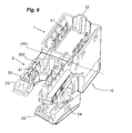
figure 8 représente le connecteur de l'invention en version UTP dans lequel l'organe de verrouillage est ouvert, - la
figure 9 représente le connecteur de l'invention en version UTP en position ouverte.
- the
figure 1 represents the connector of the invention in STP version in closed position, - the
figure 2 represents the connector of the invention in STP version in which the locking member is open, - the
Figures 3 and 4 represent, according to two distinct angles of view, the connector of the invention in STP version in open position, - the
figure 5 represents a detail of thefigure 3 identified by the circle on thisfigure 3 , - the
figure 6 represents the locking member used in the flange mechanism, - the
figure 7 represents the connector of the invention in UTP version in closed position, - the
figure 8 represents the connector of the invention in UTP version in which the locking member is open, - the
figure 9 represents the connector of the invention in UTP version in open position.
Dans la suite de la description, on définit un axe principal (A) par la direction d'introduction du connecteur de l'invention dans un connecteur correspondant, cet axe passant par l'avant et l'arrière du connecteur.In the remainder of the description, a main axis (A) is defined by the insertion direction of the connector of the invention in a corresponding connector, this axis passing through the front and the rear of the connector.
Le connecteur basse tension selon l'invention est de type Jack, plus précisément de type RJ (pour "Registered Jack"), pour pouvoir être utilisé dans un système de communication fonctionnant par exemple sous le protocole Ethernet. Le connecteur selon l'invention est de type femelle.The low-voltage connector according to the invention is of the Jack type, more precisely of RJ type (for "Registered Jack"), to be used in a communication system operating for example under the Ethernet protocol. The connector according to the invention is of the female type.
Le connecteur femelle selon l'invention présente deux configurations distinctes selon que le câble auquel il est raccordé est blindé (STP pour "Shielded Twisted Pair" ou FTP pour "Foiled Twisted Pair") ou non-blindé (UTP pour "Unshielded Twisted Pair"). La description ci-dessous s'adresse aux deux versions du connecteur, la version STP étant représentée sur les
Des références communes sont utilisées pour les deux versions du connecteur dans la mesure où les éléments référencés présentent une fonction identique dans les deux versions.Common references are used for both versions of the connector because the referenced elements have the same function in both versions.
Dans les deux configurations, le connecteur comporte un corps constitué de deux parties 1, 2, une première partie 1 et une deuxième partie 2 reliées entre elles par une liaison en pivot réalisée autour d'un premier axe de rotation (R1) perpendiculaire à l'axe principal (A). Le connecteur est ainsi susceptible d'être en position ouverte lors de l'assemblage sur le câble ou en position fermée lorsque son assemblage sur le câble est terminé.In both configurations, the connector comprises a body consisting of two
La première partie 1 présente une face avant 10 formant un logement ou empreinte (non visible) destiné à recevoir un connecteur mâle complémentaire (non représenté). Des lamelles souples, au nombre de huit dans un connecteur RJ45, sont prévues dans le logement. Ces lamelles souples sont aptes à se déformer élastiquement lors de l'enfichage du connecteur mâle complémentaire pour établir un contact électrique avec des pistes formées sur le connecteur mâle complémentaire.The
En référence aux
De manière bien connue et comme représenté sur les
La deuxième partie 2 comporte pour sa part une partie fixe 23 et un organe de verrouillage 22 qui est mobile entre une position d'ouverture et une position de fermeture par rapport à la partie fixe 23.The
La partie fixe 23 comporte un support 20 organisateur des fils du câble constitué d'une pièce plastique moulée formant plusieurs plots définissant entre eux plusieurs fentes 200 constituant chacune un emplacement pour recevoir un fil du câble. Le support 20 comporte deux rangées d'emplacements, avec un emplacement correspondant à chaque contact autodénudant 11 présent sur la première partie 1 du connecteur. Préalablement à leur connexion avec les contacts autodénudants 11, les fils du câble sont répartis sur le support 20 organisateur, chacun bloqué dans une fente 200 de celui-ci.The
Par ailleurs, dans la version STP du connecteur, une pièce métallique 3 (
Dans la version UTP du connecteur (
Lorsque l'organe de verrouillage 22 est en position de fermeture, la deuxième partie 2 comporte une ouverture 21 formant le chemin de passage du câble. L'ouverture 21 est formée à l'arrière du connecteur, suivant l'axe principal (A) lorsque le connecteur est fermé. Cette ouverture est réalisée de manière à déboucher entre les deux rangées de plots du support 20 organisateur de fils. Les fils du câble accèdent donc au support 20 organisateur de fils par l'arrière du connecteur. L'ouverture 21 est réalisée de manière à aboutir sensiblement au centre du support 20 organisateur de fils pour faciliter la distribution des fils du câble vers leur fente 200 respective sur le support 20.When the locking
Préférentiellement, l'ouverture 21 est réalisée sous la forme d'une large fente débouchant sur l'extérieur et dont l'embouchure peut être fermée ou ouverte selon la position de l'organe de verrouillage 22. Lorsque l'organe de verrouillage 22 est en position d'ouverture (
Selon l'invention, l'organe de verrouillage 22 est destiné à venir serrer localement le pourtour du câble contre les bords de l'ouverture 21. L'organe de verrouillage 22 permet de sécuriser et verrouiller le câble sur le connecteur avant la répartition des fils sur le support 20 organisateur de fils. L'organe de verrouillage 22 est par exemple mobile en rotation par rapport à la partie fixe 23 autour d'un second axe de rotation (R2,
L'organe de verrouillage 22 comporte par exemple des moyens d'indexation lui permettant de stationner en position d'ouverture.The locking
La deuxième partie 2 du connecteur comporte des moyens de maintien de l'organe de verrouillage 22 en position de fermeture. Dans la version STP du connecteur, ces moyens de maintien se présentent par exemple sous la forme d'un crochet 230 (
En référence à la
Selon l'invention, le connecteur comporte également un système de fermeture du connecteur pour verrouiller la première partie 1 sur la deuxième partie 2. Ce système est par exemple composé d'un organe de fermeture, par exemple un crochet 12, réalisé sur la première partie 1 et d'un organe de fermeture complémentaire, par exemple une fente 24, réalisée sur la deuxième partie 2. L'invention présente la particularité que l'organe de fermeture de la deuxième partie 2, c'est-à-dire la fente 24, est formé sur l'organe de verrouillage 22. De cette manière, le connecteur ne peut être fermé et verrouillé que lorsque l'organe de verrouillage 22 est lui-même en position de fermeture. Ainsi, l'installateur est incité à d'abord verrouiller le câble sur la deuxième partie 2 du connecteur avant de rabattre cette deuxième partie 2 sur la première partie 1 pour fermer le connecteur. Lorsque le câble est sécurisé sur la deuxième partie 2 du connecteur, l'installateur peut répartir les fils sur le support 20 organisateur de fils en évitant tout risque d'arrachage du câble et tout désengagement intempestif des fils de leurs emplacements sur le support 20. Sur les
Sur les deux versions du connecteur, un bouton 4 peut être prévu pour désengager le crochet 12 de la fente 24 et ainsi ouvrir le connecteur par pivotement de la deuxième partie 2 par rapport à la première partie 1 ou inversement.On both versions of the connector, a
Le montage d'un connecteur de version STP sur un câble STP ou équivalent est réalisé de la manière suivante :
- l'installateur ouvre le connecteur en appuyant sur le bouton 4 permettant de faire pivoter le crochet 12,
- une fois le connecteur ouvert, l'installateur appuie sur le bouton 231 pour désengager le crochet 230 de l'élément de fermeture 220 complémentaire et ouvrir ainsi l'organe de verrouillage 22,
- le câble dont la gaine externe est dénudée à son extrémité est amené par translation à travers l'ouverture 21 ainsi dégagée,
- le câble est verrouillé sur la deuxième partie 2 du connecteur en ramenant l'organe de verrouillage 22 dans sa position de fermeture,
- l'installateur répartit les fils dans les fentes 200 du
support 20 organisateur de fils et passe le drain en contact avec la pièce métallique 3 prévue à cet effet, - lorsque tous les fils sont correctement répartis, l'installateur arase les extrémités des fils qui dépassent,
- l'installateur ramène la deuxième partie 2 du connecteur sur la première partie 1 du connecteur de manière à insérer les fils du câble dans les contacts autodénudants 11 qui se dressent sur la première partie 1 en vis-à-vis des emplacements du
support 20 organisateur de fils, - le connecteur est alors fermé et assemblé sur le câble.
- the installer opens the connector by pressing the
button 4 to rotate thehook 12, - once the connector is open, the installer presses the
button 231 to disengage thehook 230 from thecomplementary closure element 220 and thereby open the lockingmember 22, - the cable whose outer sheath is stripped at its end is conveyed through the
opening 21 thus disengaged, - the cable is locked on the
second part 2 of the connector by bringing the lockingmember 22 into its closed position, - the installer distributes the son in the
slots 200 of thesupport 20 son organizer and passes the drain in contact with themetal part 3 provided for this purpose, - when all the wires are correctly distributed, the installer flushes the ends of the wires that protrude,
- the installer brings the
second part 2 of the connector to thefirst part 1 of the connector so as to insert the wires of the cable in theinsulation displacement contacts 11 which stand on thefirst part 1 opposite the locations of thesupport 20 organizer of son, - the connector is then closed and assembled on the cable.
Claims (9)
- Low-voltage connector for communication system, said connector being intended to receive a cable provided with a number of wires, and comprising:- a first part (1) suitable for being connected by its front face (10) to a complementary connector and comprising insulation-displacement contacts (11) to each of which one of the wires contained in the cable can be connected,- a second part (2) comprising an opening (21) forming a cable entry path and supporting a support (20) organizing wires of the cable which comprises a number of positions intended to each receive an end of a wire of the cable for it to be inserted into an insulation displacement contact (11) of the first part (1),- a hinge mechanism for articulating the second part relative to the first part about a first rotation axis (R1) in order to open or close the connector,- the connector comprising
a locking member (22) assembled on the second part (2) of the connector and intended to lock the cable in the opening (21) of the second part (2) of the connector,- the locking member (22) comprising
a closure member suitable for
cooperating with a complementary closure member produced on the first part (1) to fix the first part (1) onto the second part (2) characterized in that:- the locking member (22) pivots between a position of opening and a position of closure and articulated on a fixed part (23) about a second rotation axis (R2) at right angles to the first rotation axis (R1). - Connector according to Claim 1, characterized in that the second part (2) comprises means for holding the locking member (22) in the closure position on the fixed part (23), said holding means comprising a catch (230) suitable for co-operating with a complementary closure element (220).
- Connector according to Claim 2, characterized in that the second rotation axis (R2) is parallel to the cable entry path through the opening (21).
- Connector according to one of Claims 1 to 3, characterized in that the locking member (22) comprises a gripping piece (221) that is transversely translationally mobile relative to the cable entry path and assembled on a spring (222).
- Connector according to one of Claims 1 to 4, characterized in that the opening (21) is in the form of a slot intended to receive the cable in a translational movement parallel to its axis, and the mouth of which is open or closed depending on the position of the locking member (22).
- Connector according to one of Claims 1 to 5, characterized in that the second part (2) comprises a metal piece (3) arranged on the wire organizing support (20) to receive the drain of the cable and in electrical contact with the body made of metallic material of the second part (2).
- Connector according to one of Claims 1 to 6, characterized in that the closure member comprises a slot (24) suitable for cooperating with a catch (12) produced on the first part (1).
- Connector according to Claim 7, characterized in that the catch (12) can be actuated by pivoting using a button (4).
- Method for mounting a low-voltage connector as defined in one of Claims 1 to 8 on a cable provided with a number of wires, the method being characterized in that it comprises:- a step of passing the cable through the opening (21) produced through the second part (2) of the connector,- a step of locking the cable on the second part (2) of the connector,- a step of organising the wires of the cable on the wire organizing support (20),- a step of closing of the connector by pivoting the second part (2) onto the first part (1) so as to insert the wires of the cable into the insulation-displacement contacts (11).
Applications Claiming Priority (1)
| Application Number | Priority Date | Filing Date | Title |
|---|---|---|---|
| FR1051861A FR2957720B1 (en) | 2010-03-16 | 2010-03-16 | LOW VOLTAGE CONNECTOR FOR COMMUNICATION SYSTEM |
Publications (2)
| Publication Number | Publication Date |
|---|---|
| EP2367238A1 EP2367238A1 (en) | 2011-09-21 |
| EP2367238B1 true EP2367238B1 (en) | 2015-12-16 |
Family
ID=42697278
Family Applications (1)
| Application Number | Title | Priority Date | Filing Date |
|---|---|---|---|
| EP11154502.6A Active EP2367238B1 (en) | 2010-03-16 | 2011-02-15 | Low voltage connector for communication system |
Country Status (4)
| Country | Link |
|---|---|
| EP (1) | EP2367238B1 (en) |
| DK (1) | DK2367238T3 (en) |
| ES (1) | ES2561498T3 (en) |
| FR (1) | FR2957720B1 (en) |
Family Cites Families (5)
| Publication number | Priority date | Publication date | Assignee | Title |
|---|---|---|---|---|
| US6371794B1 (en) * | 1998-10-13 | 2002-04-16 | The Siemon Company | Telecommunications plug and adapter |
| DK174636B1 (en) * | 1999-12-30 | 2003-08-04 | Lk As | Termination device e.g. for a multi-connector |
| TW537544U (en) * | 2002-03-12 | 2003-06-11 | Jyh Eng Ind Co Ltd | Rotating pressure conductive and piercing type terminal connector |
| TW200414634A (en) * | 2003-01-16 | 2004-08-01 | John Peng | Insulation displacement connector and manufacturing method thereof |
| FR2923659B1 (en) * | 2007-11-13 | 2009-12-11 | Legrand France | EASY ASSEMBLY CONNECTOR FOR MULTICONDUCTOR CABLE. |
-
2010
- 2010-03-16 FR FR1051861A patent/FR2957720B1/en not_active Expired - Fee Related
-
2011
- 2011-02-15 DK DK11154502.6T patent/DK2367238T3/en active
- 2011-02-15 ES ES11154502.6T patent/ES2561498T3/en active Active
- 2011-02-15 EP EP11154502.6A patent/EP2367238B1/en active Active
Also Published As
| Publication number | Publication date |
|---|---|
| EP2367238A1 (en) | 2011-09-21 |
| FR2957720B1 (en) | 2012-04-13 |
| FR2957720A1 (en) | 2011-09-23 |
| DK2367238T3 (en) | 2016-02-01 |
| ES2561498T3 (en) | 2016-02-26 |
Similar Documents
| Publication | Publication Date | Title |
|---|---|---|
| EP0625809B1 (en) | Electrical connector with insertion and extraction drawer | |
| FR2768862A1 (en) | Low current plug | |
| FR2584539A1 (en) | INSERT FOR ELECTRICAL CONNECTOR AND THIS CONNECTOR | |
| FR2741204A1 (en) | ASSEMBLY OF ELECTRICAL CONNECTOR | |
| FR2720197A1 (en) | Connector for electric cable. | |
| FR2694456A1 (en) | "Modular jack" type female socket with integrated connectors. | |
| FR3051079A1 (en) | LOCKING DEVICE FOR ELECTRICAL CONNECTORS AND ELECTRICAL CONNECTORS EQUIPPED WITH THE DEVICE. | |
| EP0596776B1 (en) | Contact bank with adaptable labelling | |
| EP3227966B1 (en) | Electrical connection element penetrating an electrical wire insulation sheath | |
| FR3089068A1 (en) | MULTIPLE OUTPUT CONNECTOR | |
| EP0805605A1 (en) | Interconnecting device for transmission networks, especially for telephony and data processing | |
| EP2839546B1 (en) | Quick one-way connection system | |
| FR3025947A1 (en) | INSULATING BODY FOR DETACHABLE CONNECTOR | |
| EP2367238B1 (en) | Low voltage connector for communication system | |
| EP1999823B1 (en) | Low voltage connector | |
| EP1143580B1 (en) | Electrical connector | |
| EP0062579B1 (en) | Connection device | |
| EP0308307A1 (en) | Separable connection device between a conductive pin and at least one connection wire | |
| EP3336967B1 (en) | Electrical connection element | |
| EP2503644B1 (en) | Electrical device of terminal block type | |
| WO2008099093A2 (en) | Connector with simplified mounting for a multiple conductor cable | |
| EP3758166B1 (en) | Electrical connection device | |
| FR2813997A1 (en) | Connector for conductor wire to printed circuit has blade with flanges to retain wire and spaced contacts to fit into hole in circuit board | |
| FR2815775A1 (en) | Telephone information plug low current modular jack having rapid electrical connections using comb section/teeth and self stripping contacts with removable cover mounted support section pivoting above. | |
| FR2469016A1 (en) | Electrical cable connector - is formed from two engageable plastics pieces with one having teeth for locking wires in openings in other |
Legal Events
| Date | Code | Title | Description |
|---|---|---|---|
| PUAI | Public reference made under article 153(3) epc to a published international application that has entered the european phase |
Free format text: ORIGINAL CODE: 0009012 |
|
| AK | Designated contracting states |
Kind code of ref document: A1 Designated state(s): AL AT BE BG CH CY CZ DE DK EE ES FI FR GB GR HR HU IE IS IT LI LT LU LV MC MK MT NL NO PL PT RO RS SE SI SK SM TR |
|
| AX | Request for extension of the european patent |
Extension state: BA ME |
|
| 17P | Request for examination filed |
Effective date: 20111003 |
|
| 17Q | First examination report despatched |
Effective date: 20140103 |
|
| GRAP | Despatch of communication of intention to grant a patent |
Free format text: ORIGINAL CODE: EPIDOSNIGR1 |
|
| RIC1 | Information provided on ipc code assigned before grant |
Ipc: H01R 107/00 20060101ALI20150904BHEP Ipc: H01R 24/64 20110101ALN20150904BHEP Ipc: H01R 13/58 20060101AFI20150904BHEP Ipc: H01R 13/506 20060101ALN20150904BHEP Ipc: H01R 4/24 20060101ALN20150904BHEP |
|
| INTG | Intention to grant announced |
Effective date: 20150922 |
|
| GRAS | Grant fee paid |
Free format text: ORIGINAL CODE: EPIDOSNIGR3 |
|
| GRAA | (expected) grant |
Free format text: ORIGINAL CODE: 0009210 |
|
| AK | Designated contracting states |
Kind code of ref document: B1 Designated state(s): AL AT BE BG CH CY CZ DE DK EE ES FI FR GB GR HR HU IE IS IT LI LT LU LV MC MK MT NL NO PL PT RO RS SE SI SK SM TR |
|
| REG | Reference to a national code |
Ref country code: GB Ref legal event code: FG4D Free format text: NOT ENGLISH |
|
| REG | Reference to a national code |
Ref country code: CH Ref legal event code: EP |
|
| REG | Reference to a national code |
Ref country code: IE Ref legal event code: FG4D Free format text: LANGUAGE OF EP DOCUMENT: FRENCH |
|
| REG | Reference to a national code |
Ref country code: AT Ref legal event code: REF Ref document number: 765963 Country of ref document: AT Kind code of ref document: T Effective date: 20160115 Ref country code: FR Ref legal event code: PLFP Year of fee payment: 6 |
|
| REG | Reference to a national code |
Ref country code: DE Ref legal event code: R096 Ref document number: 602011021964 Country of ref document: DE |
|
| REG | Reference to a national code |
Ref country code: DK Ref legal event code: T3 Effective date: 20160126 |
|
| REG | Reference to a national code |
Ref country code: ES Ref legal event code: FG2A Ref document number: 2561498 Country of ref document: ES Kind code of ref document: T3 Effective date: 20160226 |
|
| REG | Reference to a national code |
Ref country code: SE Ref legal event code: TRGR |
|
| REG | Reference to a national code |
Ref country code: NL Ref legal event code: MP Effective date: 20151216 |
|
| REG | Reference to a national code |
Ref country code: LT Ref legal event code: MG4D |
|
| PG25 | Lapsed in a contracting state [announced via postgrant information from national office to epo] |
Ref country code: NO Free format text: LAPSE BECAUSE OF FAILURE TO SUBMIT A TRANSLATION OF THE DESCRIPTION OR TO PAY THE FEE WITHIN THE PRESCRIBED TIME-LIMIT Effective date: 20160316 Ref country code: LT Free format text: LAPSE BECAUSE OF FAILURE TO SUBMIT A TRANSLATION OF THE DESCRIPTION OR TO PAY THE FEE WITHIN THE PRESCRIBED TIME-LIMIT Effective date: 20151216 Ref country code: HR Free format text: LAPSE BECAUSE OF FAILURE TO SUBMIT A TRANSLATION OF THE DESCRIPTION OR TO PAY THE FEE WITHIN THE PRESCRIBED TIME-LIMIT Effective date: 20151216 |
|
| REG | Reference to a national code |
Ref country code: AT Ref legal event code: MK05 Ref document number: 765963 Country of ref document: AT Kind code of ref document: T Effective date: 20151216 |
|
| PG25 | Lapsed in a contracting state [announced via postgrant information from national office to epo] |
Ref country code: FI Free format text: LAPSE BECAUSE OF FAILURE TO SUBMIT A TRANSLATION OF THE DESCRIPTION OR TO PAY THE FEE WITHIN THE PRESCRIBED TIME-LIMIT Effective date: 20151216 Ref country code: BE Free format text: LAPSE BECAUSE OF NON-PAYMENT OF DUE FEES Effective date: 20160229 Ref country code: NL Free format text: LAPSE BECAUSE OF FAILURE TO SUBMIT A TRANSLATION OF THE DESCRIPTION OR TO PAY THE FEE WITHIN THE PRESCRIBED TIME-LIMIT Effective date: 20151216 Ref country code: LV Free format text: LAPSE BECAUSE OF FAILURE TO SUBMIT A TRANSLATION OF THE DESCRIPTION OR TO PAY THE FEE WITHIN THE PRESCRIBED TIME-LIMIT Effective date: 20151216 Ref country code: RS Free format text: LAPSE BECAUSE OF FAILURE TO SUBMIT A TRANSLATION OF THE DESCRIPTION OR TO PAY THE FEE WITHIN THE PRESCRIBED TIME-LIMIT Effective date: 20151216 |
|
| PG25 | Lapsed in a contracting state [announced via postgrant information from national office to epo] |
Ref country code: CZ Free format text: LAPSE BECAUSE OF FAILURE TO SUBMIT A TRANSLATION OF THE DESCRIPTION OR TO PAY THE FEE WITHIN THE PRESCRIBED TIME-LIMIT Effective date: 20151216 |
|
| PG25 | Lapsed in a contracting state [announced via postgrant information from national office to epo] |
Ref country code: IS Free format text: LAPSE BECAUSE OF FAILURE TO SUBMIT A TRANSLATION OF THE DESCRIPTION OR TO PAY THE FEE WITHIN THE PRESCRIBED TIME-LIMIT Effective date: 20160416 Ref country code: SM Free format text: LAPSE BECAUSE OF FAILURE TO SUBMIT A TRANSLATION OF THE DESCRIPTION OR TO PAY THE FEE WITHIN THE PRESCRIBED TIME-LIMIT Effective date: 20151216 Ref country code: EE Free format text: LAPSE BECAUSE OF FAILURE TO SUBMIT A TRANSLATION OF THE DESCRIPTION OR TO PAY THE FEE WITHIN THE PRESCRIBED TIME-LIMIT Effective date: 20151216 Ref country code: SK Free format text: LAPSE BECAUSE OF FAILURE TO SUBMIT A TRANSLATION OF THE DESCRIPTION OR TO PAY THE FEE WITHIN THE PRESCRIBED TIME-LIMIT Effective date: 20151216 Ref country code: AT Free format text: LAPSE BECAUSE OF FAILURE TO SUBMIT A TRANSLATION OF THE DESCRIPTION OR TO PAY THE FEE WITHIN THE PRESCRIBED TIME-LIMIT Effective date: 20151216 Ref country code: RO Free format text: LAPSE BECAUSE OF FAILURE TO SUBMIT A TRANSLATION OF THE DESCRIPTION OR TO PAY THE FEE WITHIN THE PRESCRIBED TIME-LIMIT Effective date: 20151216 Ref country code: PT Free format text: LAPSE BECAUSE OF FAILURE TO SUBMIT A TRANSLATION OF THE DESCRIPTION OR TO PAY THE FEE WITHIN THE PRESCRIBED TIME-LIMIT Effective date: 20160418 |
|
| REG | Reference to a national code |
Ref country code: DE Ref legal event code: R097 Ref document number: 602011021964 Country of ref document: DE |
|
| PG25 | Lapsed in a contracting state [announced via postgrant information from national office to epo] |
Ref country code: MC Free format text: LAPSE BECAUSE OF FAILURE TO SUBMIT A TRANSLATION OF THE DESCRIPTION OR TO PAY THE FEE WITHIN THE PRESCRIBED TIME-LIMIT Effective date: 20151216 Ref country code: LU Free format text: LAPSE BECAUSE OF FAILURE TO SUBMIT A TRANSLATION OF THE DESCRIPTION OR TO PAY THE FEE WITHIN THE PRESCRIBED TIME-LIMIT Effective date: 20160215 |
|
| REG | Reference to a national code |
Ref country code: CH Ref legal event code: PL |
|
| PLBE | No opposition filed within time limit |
Free format text: ORIGINAL CODE: 0009261 |
|
| STAA | Information on the status of an ep patent application or granted ep patent |
Free format text: STATUS: NO OPPOSITION FILED WITHIN TIME LIMIT |
|
| PG25 | Lapsed in a contracting state [announced via postgrant information from national office to epo] |
Ref country code: PL Free format text: LAPSE BECAUSE OF FAILURE TO SUBMIT A TRANSLATION OF THE DESCRIPTION OR TO PAY THE FEE WITHIN THE PRESCRIBED TIME-LIMIT Effective date: 20151216 Ref country code: LI Free format text: LAPSE BECAUSE OF NON-PAYMENT OF DUE FEES Effective date: 20160229 Ref country code: CH Free format text: LAPSE BECAUSE OF NON-PAYMENT OF DUE FEES Effective date: 20160229 |
|
| 26N | No opposition filed |
Effective date: 20160919 |
|
| REG | Reference to a national code |
Ref country code: IE Ref legal event code: MM4A |
|
| REG | Reference to a national code |
Ref country code: FR Ref legal event code: PLFP Year of fee payment: 7 |
|
| PG25 | Lapsed in a contracting state [announced via postgrant information from national office to epo] |
Ref country code: IE Free format text: LAPSE BECAUSE OF NON-PAYMENT OF DUE FEES Effective date: 20160215 |
|
| PG25 | Lapsed in a contracting state [announced via postgrant information from national office to epo] |
Ref country code: SI Free format text: LAPSE BECAUSE OF FAILURE TO SUBMIT A TRANSLATION OF THE DESCRIPTION OR TO PAY THE FEE WITHIN THE PRESCRIBED TIME-LIMIT Effective date: 20151216 |
|
| PG25 | Lapsed in a contracting state [announced via postgrant information from national office to epo] |
Ref country code: MT Free format text: LAPSE BECAUSE OF FAILURE TO SUBMIT A TRANSLATION OF THE DESCRIPTION OR TO PAY THE FEE WITHIN THE PRESCRIBED TIME-LIMIT Effective date: 20151216 |
|
| REG | Reference to a national code |
Ref country code: FR Ref legal event code: PLFP Year of fee payment: 8 |
|
| PG25 | Lapsed in a contracting state [announced via postgrant information from national office to epo] |
Ref country code: CY Free format text: LAPSE BECAUSE OF FAILURE TO SUBMIT A TRANSLATION OF THE DESCRIPTION OR TO PAY THE FEE WITHIN THE PRESCRIBED TIME-LIMIT Effective date: 20151216 Ref country code: HU Free format text: LAPSE BECAUSE OF FAILURE TO SUBMIT A TRANSLATION OF THE DESCRIPTION OR TO PAY THE FEE WITHIN THE PRESCRIBED TIME-LIMIT; INVALID AB INITIO Effective date: 20110215 |
|
| PG25 | Lapsed in a contracting state [announced via postgrant information from national office to epo] |
Ref country code: MK Free format text: LAPSE BECAUSE OF FAILURE TO SUBMIT A TRANSLATION OF THE DESCRIPTION OR TO PAY THE FEE WITHIN THE PRESCRIBED TIME-LIMIT Effective date: 20151216 Ref country code: GR Free format text: LAPSE BECAUSE OF FAILURE TO SUBMIT A TRANSLATION OF THE DESCRIPTION OR TO PAY THE FEE WITHIN THE PRESCRIBED TIME-LIMIT Effective date: 20151216 Ref country code: TR Free format text: LAPSE BECAUSE OF FAILURE TO SUBMIT A TRANSLATION OF THE DESCRIPTION OR TO PAY THE FEE WITHIN THE PRESCRIBED TIME-LIMIT Effective date: 20151216 |
|
| PG25 | Lapsed in a contracting state [announced via postgrant information from national office to epo] |
Ref country code: BG Free format text: LAPSE BECAUSE OF FAILURE TO SUBMIT A TRANSLATION OF THE DESCRIPTION OR TO PAY THE FEE WITHIN THE PRESCRIBED TIME-LIMIT Effective date: 20151216 |
|
| PG25 | Lapsed in a contracting state [announced via postgrant information from national office to epo] |
Ref country code: AL Free format text: LAPSE BECAUSE OF FAILURE TO SUBMIT A TRANSLATION OF THE DESCRIPTION OR TO PAY THE FEE WITHIN THE PRESCRIBED TIME-LIMIT Effective date: 20151216 |
|
| PGFP | Annual fee paid to national office [announced via postgrant information from national office to epo] |
Ref country code: ES Payment date: 20240307 Year of fee payment: 14 |
|
| PGFP | Annual fee paid to national office [announced via postgrant information from national office to epo] |
Ref country code: DE Payment date: 20240228 Year of fee payment: 14 Ref country code: GB Payment date: 20240220 Year of fee payment: 14 |
|
| PGFP | Annual fee paid to national office [announced via postgrant information from national office to epo] |
Ref country code: SE Payment date: 20240226 Year of fee payment: 14 Ref country code: IT Payment date: 20240222 Year of fee payment: 14 Ref country code: FR Payment date: 20240226 Year of fee payment: 14 Ref country code: DK Payment date: 20240226 Year of fee payment: 14 |