EP3089295B1 - Electrical interconnection device for an equipotential connection between a cable tray piece and an electrical cable piece. - Google Patents
Electrical interconnection device for an equipotential connection between a cable tray piece and an electrical cable piece. Download PDFInfo
- Publication number
- EP3089295B1 EP3089295B1 EP16166335.6A EP16166335A EP3089295B1 EP 3089295 B1 EP3089295 B1 EP 3089295B1 EP 16166335 A EP16166335 A EP 16166335A EP 3089295 B1 EP3089295 B1 EP 3089295B1
- Authority
- EP
- European Patent Office
- Prior art keywords
- section
- wall
- cable
- elastic metal
- metal clip
- Prior art date
- Legal status (The legal status is an assumption and is not a legal conclusion. Google has not performed a legal analysis and makes no representation as to the accuracy of the status listed.)
- Active
Links
- 230000009975 flexible effect Effects 0.000 claims description 85
- 239000002184 metal Substances 0.000 claims description 80
- 229910052751 metal Inorganic materials 0.000 claims description 80
- 230000004308 accommodation Effects 0.000 claims description 16
- 238000003780 insertion Methods 0.000 claims description 6
- 230000037431 insertion Effects 0.000 claims description 6
- 210000002105 tongue Anatomy 0.000 description 27
- 210000004027 cell Anatomy 0.000 description 4
- 238000004519 manufacturing process Methods 0.000 description 4
- 210000000078 claw Anatomy 0.000 description 2
- 238000009434 installation Methods 0.000 description 2
- 238000000926 separation method Methods 0.000 description 2
- RYGMFSIKBFXOCR-UHFFFAOYSA-N Copper Chemical compound [Cu] RYGMFSIKBFXOCR-UHFFFAOYSA-N 0.000 description 1
- 229910001335 Galvanized steel Inorganic materials 0.000 description 1
- 240000008042 Zea mays Species 0.000 description 1
- 238000012550 audit Methods 0.000 description 1
- 229910052802 copper Inorganic materials 0.000 description 1
- 239000010949 copper Substances 0.000 description 1
- 230000006355 external stress Effects 0.000 description 1
- 239000008397 galvanized steel Substances 0.000 description 1
- 238000002955 isolation Methods 0.000 description 1
- 239000007769 metal material Substances 0.000 description 1
- 230000000717 retained effect Effects 0.000 description 1
Images


Classifications
-
- H—ELECTRICITY
- H02—GENERATION; CONVERSION OR DISTRIBUTION OF ELECTRIC POWER
- H02G—INSTALLATION OF ELECTRIC CABLES OR LINES, OR OF COMBINED OPTICAL AND ELECTRIC CABLES OR LINES
- H02G3/00—Installations of electric cables or lines or protective tubing therefor in or on buildings, equivalent structures or vehicles
- H02G3/02—Details
- H02G3/04—Protective tubing or conduits, e.g. cable ladders or cable troughs
- H02G3/0437—Channels
- H02G3/0443—Channels formed by wire or analogous netting
-
- H—ELECTRICITY
- H01—ELECTRIC ELEMENTS
- H01R—ELECTRICALLY-CONDUCTIVE CONNECTIONS; STRUCTURAL ASSOCIATIONS OF A PLURALITY OF MUTUALLY-INSULATED ELECTRICAL CONNECTING ELEMENTS; COUPLING DEVICES; CURRENT COLLECTORS
- H01R4/00—Electrically-conductive connections between two or more conductive members in direct contact, i.e. touching one another; Means for effecting or maintaining such contact; Electrically-conductive connections having two or more spaced connecting locations for conductors and using contact members penetrating insulation
- H01R4/58—Electrically-conductive connections between two or more conductive members in direct contact, i.e. touching one another; Means for effecting or maintaining such contact; Electrically-conductive connections having two or more spaced connecting locations for conductors and using contact members penetrating insulation characterised by the form or material of the contacting members
- H01R4/64—Connections between or with conductive parts having primarily a non-electric function, e.g. frame, casing, rail
-
- H—ELECTRICITY
- H01—ELECTRIC ELEMENTS
- H01R—ELECTRICALLY-CONDUCTIVE CONNECTIONS; STRUCTURAL ASSOCIATIONS OF A PLURALITY OF MUTUALLY-INSULATED ELECTRICAL CONNECTING ELEMENTS; COUPLING DEVICES; CURRENT COLLECTORS
- H01R4/00—Electrically-conductive connections between two or more conductive members in direct contact, i.e. touching one another; Means for effecting or maintaining such contact; Electrically-conductive connections having two or more spaced connecting locations for conductors and using contact members penetrating insulation
- H01R4/28—Clamped connections, spring connections
- H01R4/48—Clamped connections, spring connections utilising a spring, clip, or other resilient member
Definitions
- the invention relates to electrical interconnection devices configured to establish an equipotential link between a section of cable tray and a section of electric cable.
- the invention also relates to electrical and / or telecommunications cable routing systems, comprising at least one section of cable duct, at least one section of an uninsulated electric cable, and at least one such interconnection device. electric.
- Electric cable routing systems comprising a section of cable duct having the shape of a gutter and having warp threads which extend longitudinally and U-shaped weft threads which extend transversely, a section of an uninsulated electrical cable, and one or more electrical interconnection devices configured to establish an equipotential bond between the section of cable tray and the section of electrical cable.
- these electrical interconnection devices are configured to receive a portion of a warp wire of the cable tray section in a first housing, or related, and also to receive a portion of the uninsulated electrical cable section in a second accommodation.
- Such electrical interconnection devices can be in the form of a wire clamp, comprising a screw, two washers, a nut from which extends an open chimney laterally and whose internal wall is threaded, as well as a screw-threaded clamping plug. taken in the housing provided in the fireplace.
- the system is configured such that once assembled, two portions of two warp threads are sandwiched between the two washers (which thus define a housing) and clamped between them by means of the screw nut assembly. A portion of the electric cable crosses the chimney by through its side openings and the clamping plug clamps this portion of cable in the chimney.
- Electrode interconnection devices with jaws including a lower jaw in which two housings are formed and an upper jaw having clamping claws arranged opposite the housings. A screw brings the two jaws closer together.
- the warp wire portion and the electric cable portion are introduced at the same time into the respective dedicated housings of the lower jaw, and the upper jaw is brought closer to the lower jaw by actuation of the locking screw. so that the claws of the upper jaw clamp the portion of warp wire and the portion of electric cable in the respective dedicated housings.
- Two housings which take the form of a double U, having a bottom wall, two side walls which extend vertically to the bottom wall and a central wall, housed between the side walls, and which also extends vertically to the bottom wall and opposite the side walls.
- the warp yarn portion and the electric cable portion are introduced into the respective dedicated housings and are not retained in these housings so that these portions can be easily extracted therefrom.
- the patent application FR 2 694 141 describes a clip for grounding a cable having an outer sheath encasing a ground braid, the clip consisting of a curved metal plate having two wings facing each other and each having a cutout forming a knife for cutting the cable. sheath in order to expose the ground braid during the translation of the cable between the wings and to establish electrical contact with the ground braid.
- the patent application GB 2 467 426 describes a fishplate for assembling cable tray sections by their ends, comprising elongated elastic tabs forming a non-return once the weft son of the respective cable tray sections are introduced into the respective housings of this fishplate.
- the invention aims to provide an improved electrical interconnection device, which is particularly safe, simple, convenient and economical, both in manufacture and in use.
- a subject of the invention is thus, in a first aspect, an electrical interconnection device comprising the characteristics set out in claim 1.
- the electrical interconnection device according to the invention thanks to its shape as an elastic metal clip, can be assembled without tools both with the first portion of a warp and / or weft thread of the cable tray section and with the portion of the electric cable section.
- the elastic metal clip and the first portion of the warp and / or weft thread can be mechanically secured together by clipping thanks to the biasing of the clip on this first portion of thread so as to introduce the latter into the first slot of the clip.
- the elastic metal clip and the portion of the electrical cable section can be mechanically secured together by clipping thanks to the bias of this cable portion on this clip so as to introduce the cable portion into the second housing of this clip.
- the electrical interconnection device thanks to its flexible tongues, makes it possible to hold in position both the first portion of warp and / or weft yarn of the cable tray section and the portion of the cable section. electrical in the respective dedicated housings of the clip; these portions therefore cannot be withdrawn from the respective dedicated housings without external solicitation.
- the electrical interconnection device according to the invention thanks to its resilient clip configuration and to the flexible tongues that this clip has, also makes it possible to define first and second housings of variable sizes.
- the electrical interconnection device according to the invention is thus adaptable in that it offers the possibility of being assembled with cable trays of different sections and / or of which the warp and / or weft threads have distinct sections. ; and also to be assembled with sections of electric cable also of different sections.
- the electrical interconnection device according to the invention is therefore particularly efficient and safe while remaining particularly simple, convenient and economical, in particular during manufacture and installation.
- the subject of the invention is also, in a second aspect, a system for routing electric and / or telecommunications cables, comprising at least one section of cable duct having the shape of a gutter and having warp threads which extend. longitudinally and U-shaped weft threads which extend transversely, at least one section of an uninsulated electric cable, and at least one electric interconnection device such as that described above and in accordance with the invention.
- the electrical and / or telecommunications cable routing system according to the invention can be assembled and disassembled mechanically without tools and is particularly efficient and safe while remaining particularly simple, convenient and economical, in particular in manufacture and in use.
- said at least one clip elastic metal is configured to receive a portion of a warp wire of said at least one section of cable tray in its first housing and to receive a portion of said at least one section of uninsulated electric cable in its second housing.
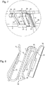
- the figure 1 illustrates a system 1 for routing electric and / or telecommunications cables (not shown).
- This system 1 here comprises a section of cable tray 2 having the shape of a gutter and having warp yarns 3 which extend longitudinally and weft yarns 4 in U which extend transversely.
- the warp threads 3 and the weft threads 4 are made of a metallic material, for example galvanized steel, and are usually welded to each other to form the gutter, substantially U-shaped.
- the cable tray section 2 which is configured to be fixed to a base (not shown), it has a bottom wall (not shown) extending in a horizontal plane, and two side walls (not shown). ) each connected to the bottom wall and which extend opposite each other in a vertical plane.
- the cable tray section 2 can be envisaged, for example with the bottom wall which extends in a vertical plane rather than horizontal and the two side walls which extend in a horizontal plane rather that vertical.
- This system 1 further comprises here a section of an uninsulated electric cable 5, also called a cable, which allows the connection to the ground of the section of cable tray 1.
- This cable 5 is here made of copper and has a section of between approximately 16 mm 2 to approximately 35 mm 2 .
- connection to ground or, in in other words, the establishment of an equipotential link between the warp threads 3 and the weft threads 4 and the cable 5, is generally carried out every 2 m approximately to approximately 20 m.
- the system 1 further comprises a plurality of electrical interconnection devices 6, only one of which is visible on the figure 1 , which is configured to establish the equipotential bond between the section of cable tray 2 visible on the figure 1 and the cable section 5 also visible on the figure 1 .
- the electrical interconnection device 6 is here mounted on a warp wire 3, where a portion of the latter is received in a first housing 7 of the device 6, while the cable section 5 is here mounted on this device 6, where a portion of this cable 5 is received in a second housing 8 of the device.
- the electrical interconnection device 6 will be described in detail with reference to figures 2 to 5 .
- the electrical interconnection device is formed by an elastic metal clip 6, here having the general shape of S.
- the elastic metal clip 6 comprises a main wall 10 having a first end 11 and a second end 12 opposite its first end 11.
- the elastic metal clip 6 further comprises an internal wall 13 which extends from the first end 11 of the main wall 10 and which defines with the latter the first housing 7 of this elastic metal clip 6; as well as an outer wall 14 which extends from the second end 12 of the main wall 10 and which defines with the latter the second housing 8.
- the elastic metal clip 6 comprises a first flexible tongue 15 configured to protrude into the first housing 7 and thus urge the portion of the warp wire 3 of the cable tray section 2 when it is received in the first housing 7. ; as well as a second flexible tongue 16 configured to project into the second housing 8 and thus urge the portion of the cable section 5 when it is received in the second housing 8.
- the first flexible tongue 15 is formed in the internal wall 13 while the second flexible tongue 16 is formed in the external wall 14.
- first flexible tongue 15 is produced by cutting in the internal wall 13 and the second flexible tongue 16 is produced by cutting in the external wall 14.
- the elastic metal clip 6 further comprises a non-return tab 17 formed in the second tab 16, which non-return tab 17 also projects into the second housing 8 and is configured to prevent the portion of the cable section 5 from withdrawing. of the second housing 8 without an external bias on the external wall 14.
- the internal wall 13 has two flexible arms 20 spaced apart from each other and each having a curved portion 21 extending from the first end 11 of the main wall 10 and a straight portion 22 extending the curved portion 21 and s' extending opposite the main wall 10.
- the internal wall 13 also has a junction portion 23 connecting the two flexible arms 20 by their respective straight portions 22.
- junction portion 23 of the internal wall 13 extends from the straight portions 22 of the flexible arms 20 in the direction opposite to the main wall 10 so as to form a first introduction opening 24 of the first housing 7.
- the first flexible tongue 15 protrudes from the junction portion 23 and extends between the two flexible arms 20.
- the outer wall 14 has two flexible arms 25 spaced apart from each other and each having a curved portion 26 extending from the second end 12 of the main wall 10 and a straight portion 27 extending the curved portion. 26 and extending opposite the main wall 20.
- the outer wall 14 also has a junction portion 28 connecting the two flexible arms 20 by their respective straight portions 27.
- junction portion 28 of the outer wall 14 extends from the straight portions 27 of the flexible arms 25 in the direction opposite to the wall. main 10 so as to form a second opening 29 for introducing the second housing 8.
- the second flexible tongue 16 protrudes from the junction portion 28 and extends between the two flexible arms 25.
- main wall 10 generally extends along a horizontal main plane while the flexible arms 20 and 25, respectively of the internal wall 13 and of the external wall 14, extend opposite the main wall 10 according to planes substantially inclined relative to the main horizontal plane.
- the flexible arms 20 of the internal wall 13 extend from the curved portions 21 towards the junction portion 23, approaching the first end 11 of the main wall 10, so that the first housing 7 has a first relatively narrow introduction opening 24, or at the very least which is tightened with respect to the bottom of the first housing 7 at the level of the curved portions 21.
- the flexible arms 25 of the outer wall 14 extend from the curved portions 26 towards the junction portion 28 approaching the second end 12 of the main wall 10, so that the second housing 8 has a second relatively narrow introduction opening 29, or at the very least which is tightened with respect to the bottom of the second housing 8 at the level of the curved portions 26.
- the elastic metal clip 6 further comprises here two curved support legs 30 and 31, substantially U-shaped, each extending from the first end 11 of the main wall 10 and which are provided on either side. flexible arms 20.
- These two curved support legs 30 and 31 are configured to rest on the portion of warp wire 3 of the cable tray section 2 when the elastic metal clip 6 is assembled on the latter.
- These two curved support legs 30 and 31 have here shapes quite similar to those of the shapes of the curved portions 21 of the flexible arms, which are adjacent to them.
- the system 1 further comprises a member 35 for positioning the elastic metal clip 6 on the section of cable tray 2.
- This positioning member 35 is configured to prevent the elastic metal clip 6 from moving in rotation around and / or in translation with respect to the warp yarn portion 3 of the cable tray section 2, when this clip elastic metal 6 is assembled on the section of cable tray 2.
- the positioning member 35 is here formed in one piece with the elastic metal clip 6.
- This positioning member 35 comprises a support wall 36 formed at a distance from the main wall 10 and configured to bear against a portion of a weft wire 4 of the cable tray section 2, which crosses the portion of the wire. chain 3 on which the elastic metal clip 6 is mounted.
- the support wall 36 has at a free end 37 a gutter portion 38 of convexity turned towards the side of the main wall 10.
- the positioning member 35 further comprises a window 39 formed in the support wall 36 and a lug 40 projecting from an edge 41 of the window 39 and extending from the side of the main wall 10.
- This lug 40 is configured to abut against the weft thread portion 4 of the cable tray section 2, which is then interposed between the lug 40 and the gutter portion 38.
- the support wall 36 extends here in a plane inclined relative to the main plane in which the main wall 10 extends overall.
- the positioning member 35 further comprises a junction portion 42 which is connected to the first end 11 of the main wall via a bridge formed here by the curved bearing tab 31; with the bearing wall 36 of the positioning member 35 which is connected, via an end opposite its free end 37, to the junction portion 42.
- junction portion 42 of the positioning member 35 extends here generally facing the main wall 10 and in a plane substantially parallel to the main plane in which this main wall 10 extends overall.
- the elastic metal clip 6 is approached to the cable tray section 2 through the interior of the U of the gutter that it forms, at an intersection 50 between a portion of a warp wire 3 and a portion of a weft thread 4 on a side wall of this section of cable tray 2.
- the elastic metal clip 6 is approached slightly at an angle, that is to say in a manner slightly inclined with respect to the horizontal, so that the first introduction opening 24 of its first housing 7 is in facing the portion of warp yarn 3, and that the positioning member 35 is facing the portion of weft yarn 4.
- junction portion 23 of the internal wall 13 is thus brought substantially into contact with, or in close proximity to, the portion of warp yarn 3 and the positioning member is located in the immediate vicinity of the intersection 50 between the portions of warp 3 and weft 4 yarns.
- the first flexible tongue 15 Before the introduction of the warp yarn portion 3 into the first housing 7, the first flexible tongue 15 is in a rest configuration where it is not stressed, rest configuration in which it protrudes into the first housing 7 and therefore closes it at least partially.
- junction portion 23 of the internal wall 13 is then urged against the warp yarn portion 3 to introduce the warp yarn portion 3 into the first housing 7.
- the warp yarn portion 3 is introduced into the first housing 7 by sliding against the main wall 10, from its first end 11 towards its second end 12, while acting against both the flexible arms 20, in particular straight portions 22, and the first flexible tongue 15, to separate them from the main wall 10, at least temporarily, from a respective initial position ( figure 8 ) to a respective insertion position ( figure 11 ).
- the distance between the flexible arms 20 and the first flexible tongue 15 depends on the diameter of the warp wire 3.
- the flexible arms 20 are generally only moved apart during the introduction of the portion of the warp wire 3 into the first housing. 7 and return to the initial position as soon as this portion of warp yarn 3 is sufficiently introduced into the first housing 7.
- the elastic metal clip 6 is further configured so that the further the first flexible tab 15 is from the main wall 10, the more it urges the warp yarn portion 3 so as to hold it in position in the first housing 7.
- the first flexible tab 15 is thus in a working configuration.
- the positioning member 35 is for its part positioned in abutment against the portion of weft thread 4.
- the face of the support wall 36 which is turned towards the side of the main wall 10 is applied against the portion of weft yarn 4, with the latter which is at least partially interposed, or substantially sandwiched, between the lug 40 and the gutter portion 38 of the positioning member 35.
- the cable section 5 is approached to the elastic metal clip 6 so that a portion of this cable section 5 is facing the second insertion opening 29 of the second housing 8 of the elastic metal clip 6.
- the portion of the cable section 5 is thus brought substantially into contact with, or in close proximity to, the junction portion 28 of the outer wall 14.
- the second flexible tongue 16 Before the introduction of the portion of the cable section 5 into the second housing 8, the second flexible tongue 16 is in a rest configuration where it is not stressed, rest configuration in which it protrudes into the second housing 8 and therefore closes it at least partially.
- the portion of the cable section 5 is biased against the junction portion 28 of the outer wall 14 for its introduction into the second housing 8.
- the portion of the cable section 5 is introduced into the second housing 8 by sliding against the main wall 10, from its second end 12 towards its first end 11, while acting against both flexible arms 25, in particular straight portions 27, and the second flexible tongue 16, to move them away from the main wall 10, at least temporarily, from a respective initial position ( figure 13 ) to a respective insertion position ( figure 15 ).
- the distance between the flexible arms 25 and the second flexible tongue 16 depends on the section of the cable 5.
- the flexible arms 25 can be moved apart only during the introduction of the portion of the cable section 5 in the second housing 8. and return to the initial position (or almost) as soon as this portion of cable section 5 is sufficiently introduced into the second housing 8.
- the separation of the second flexible tongue 16 vis-à-vis the main wall 10 also causes the separation of the non-return tab 17 from this same main wall 10.
- the elastic metal clip 6 is further configured so that, the further the second flexible tab 16 is spaced from the main wall 10, the more it urges the portion of cable section 5 so as to hold it in position in the second housing 8.
- the second flexible tongue 16 is thus in a working configuration.
- the elastic metal clip 6 is configured so that once the portion of cable section 5 is sufficiently inserted into the second housing 8, or at least once this portion of cable section 5 has beyond the non-return tab 17, the latter prevents the portion of cable section 5 from withdrawing from the second housing 8 without an external bias on the external wall 14.
- the elastic metal clip 6 is configured so that the smallest distance left between the free end of the non-return tab 17 and the main wall 10 is at least slightly less than the section of the cable. 5.
- the elastic metal clip 6 can thus be assembled without tools both with the portion of the warp wire 3 of the cable tray section 2 and with the portion of the cable section 5.
- the elastic metal clip 6 and the portion of the warp wire 3 can be mechanically secured together by clipping thanks to the biasing of the clip 6 on this portion of wire so as to introduce the latter into the first housing 7 of clip 6.
- the elastic metal clip 6 and the portion of the cable section 5 can be mechanically secured together by clipping thanks to the bias of this cable portion 5 on this clip 6 so as to introduce the cable portion 5 into the second housing 8 of this clip 6.
- the elastic metal clip 6, thanks to its flexible tabs 15 and 16, makes it possible to hold in position both the portion of warp wire 3 of the section of cable tray 2 and the portion of the section of cable 5 in the dedicated housings respective 7 and 8 of the clip 6; these portions therefore cannot be withdrawn from these respective dedicated housings without external solicitation.
- the electrical interconnection device is thus adaptable in that it offers the possibility of being assembled with cable trays 2 of different sections and / or of which the warp and / or weft threads have distinct diameters or sections. distinct; and also to be assembled with cable sections 5 also of different sections.
- the electrical interconnection device and the system 1 which includes it are consequently particularly efficient and safe while remaining particularly simple, convenient and economical, in particular in manufacture and in installation.
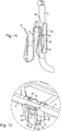
- the figures 16 and 17 show an alternative embodiment of the elastic metal clip, visible respectively in isolation and then mounted on the cable tray.
- the elastic metal clip 106 shown on figures 16 and 17 is relatively similar to the elastic metal clip 6 illustrated in particular on the figures 2 to 5 , but differs in particular by its positioning member 160.
- the resilient metal clip 106 therefore also has a general S-shape, provided with a main wall 110, an internal wall 113 which extends from the first end of the main wall 110 and which defines with this last the first housing 107, and an outer wall 114 which extends from the second end of the main wall 110 and which defines with the latter the second housing 108.
- the elastic metal clip 106 also includes a first flexible tab 115 configured to project into the first housing 107 and thus bias the portion of the warp wire 103 of the cable tray section 102 when it is received in the first housing. 107; as well as a second flexible tab 116 configured to project into the second housing 108 and thus urge the portion of the cable section when it is received in the second housing 108.
- the inner wall 113 and the outer wall 114 of the elastic metal clip 106 are similar to those of the elastic metal clip 6, except that the elastic metal clip 106 is devoid of an anti- return formed in its second flexible tongue 116.
- the inner 113 and outer 114 walls thus each have two flexible arms spaced apart from each other and each having a curved portion extending from the first end of the main wall 110, a straight portion extending the curved portion and s' extending opposite the main wall 110; as well as a junction portion connecting the two respective flexible arms by their respective straight portions and extending from the straight portions of the respective flexible arms in the direction opposite to the main wall 110 so as to form the first and second introduction openings first and second housings 107 and 108 respectively.
- the resilient metal clip 106 has only one curved support tab 131, substantially U-shaped, extending from the first end of the main wall 110 and configured to rest on the warp yarn portion 103 of the cable tray section 102 when the elastic metal clip 106 is assembled thereon.
- the positioning member 160 is here formed in one piece with the elastic metal clip 106.
- This positioning member 160 comprises a support wall 161 formed at a distance from the main wall 110, on the side of the internal wall 113, and configured to come to bear partially against a portion of weft yarn. 104 of the cable tray section 102, which crosses the warp yarn portion 103 on which the elastic metal clip 106 is mounted.
- the support wall 161 is connected to the first end of the main wall 110 via a bridge formed here by the curved support tab 131 and extends generally facing the main wall 110 and in a plane substantially parallel to the plane. main in which this main wall 110 extends overall.
- the support wall 161 has at a free end 162 a folding portion 163 which is directed, in its unfolded configuration, in a direction opposite to the internal wall 113.
- the positioning member 160 further comprises a notch 164 which is formed in the curved bearing tab 131 and the opening of which is on the side opposite to the internal wall 113.
- This notch 164 is configured to receive a portion of weft yarn 104 from the section of cable tray 102.
- a shoulder 165 is formed at the junction between the support portion 161 and the folding portion 163 so as to allow the folding of this folding portion 163 without being hampered by the weft thread, at the intersection between a portion of a warp yarn 103 and a portion of a weft yarn 104 on a side wall of this section of cable tray 102.
- the mounting of the elastic metal clip 106 on the cable tray section is as follows.
- the elastic metal clip 106 is approached to the section of cable tray 102 from the inside or the outside of the U of the gutter that it forms, at an intersection between a portion of a warp wire 103 and a portion of a weft thread 104 on a side wall of this section of cable tray 102.
- the elastic metal clip 106 is approached so that the first opening for introducing its first housing 107 is opposite the portion of warp yarn 103.
- the positioning member 160 is not at this stage. next to the weft thread portion 4.
- junction portion of the internal wall 113 is brought substantially into contact with, or in close proximity to, the portion of warp yarn 103.
- the first flexible tongue 115 Before the introduction of the warp yarn portion 103 in the first housing 107, the first flexible tongue 115 is in a rest configuration, where it is not stressed, and protrudes into the first housing 107 that it therefore closes. at least partially.
- junction portion of the internal wall 113 is then urged against the warp yarn portion 103 to introduce it into the first housing 107.
- the warp yarn portion 103 is introduced into the first housing 107 by sliding against the main wall 110, from its first end towards its second end, while acting against both the flexible arms, in particular the straight portions. , and the first flexible tongue 115, to move them away from the main wall 110, at least temporarily, from a respective initial position to a respective insertion position.
- the distance between the flexible arms and the first flexible tongue 115 depends on the diameter of the warp wire 103.
- the flexible arms are generally only moved apart during the introduction of the portion of the warp wire 103 into the first housing 107 and return to the initial position as soon as this portion of warp yarn 103 is sufficiently introduced into the first housing 107.
- the resilient metal clip 106 is further configured such that the further the first flexible tab 115 is from the main wall 110, the more it urges the warp yarn portion 103 so as to hold it in place. position in the first housing 107.
- the first flexible tongue 115 is thus in a working configuration.
- the elastic metal clip 106 is then translated onto the warp yarn portion 103 until a portion of the weft yarn 104 is introduced into the notch 164 of the positioning member 160.
- the elastic metal clip 106 is then in abutment against the portion of the weft thread 104.
- the hinged portion 163 is then folded back by folding over a portion of weft yarn 4, which is then at least partially interposed, or substantially sandwiched, between this hinged portion 163 and the curved support tab 131, at the level of the 'notch 164.
- the hinged portion 163 is thus in its folded configuration where it extends transversely with respect to the main wall 110 and is directed towards the side of the outer wall 114.
- the mounting of the portion of the cable section in the second housing 108 of the elastic metal clip 106 is done in exactly the same way as in the second housing 8 of the elastic metal clip 6.
Landscapes
- Engineering & Computer Science (AREA)
- Architecture (AREA)
- Civil Engineering (AREA)
- Structural Engineering (AREA)
- Installation Of Indoor Wiring (AREA)
Description
L'invention a trait aux dispositifs d'interconnexion électrique configurés pour établir une liaison équipotentielle entre un tronçon de chemin de câbles et un tronçon de câble électrique.The invention relates to electrical interconnection devices configured to establish an equipotential link between a section of cable tray and a section of electric cable.
L'invention a également trait aux systèmes de cheminement de câbles électriques et/ou de télécommunications, comportant au moins un tronçon de chemin de câbles, au moins un tronçon d'un câble électrique non isolé, et au moins un tel dispositif d'interconnexion électrique.The invention also relates to electrical and / or telecommunications cable routing systems, comprising at least one section of cable duct, at least one section of an uninsulated electric cable, and at least one such interconnection device. electric.
On connaît déjà des systèmes de cheminement de câbles électriques comportant un tronçon de chemin de câbles ayant une forme de gouttière et présentant des fils de chaîne qui s'étendent longitudinalement et des fils de trame en U qui s'étendent transversalement, un tronçon d'un câble électrique non isolé, et un ou plusieurs dispositifs d'interconnexion électrique configurés pour établir une liaison équipotentielle entre le tronçon de chemin de câbles et le tronçon de câble électrique.Electric cable routing systems are already known comprising a section of cable duct having the shape of a gutter and having warp threads which extend longitudinally and U-shaped weft threads which extend transversely, a section of an uninsulated electrical cable, and one or more electrical interconnection devices configured to establish an equipotential bond between the section of cable tray and the section of electrical cable.
Plus précisément, ces dispositifs d'interconnexion électrique sont configurés pour recevoir une portion d'un fil de chaîne du tronçon de chemin de câbles dans un premier logement, ou apparenté, et aussi pour recevoir une portion du tronçon de câble électrique non isolé dans un second logement.More specifically, these electrical interconnection devices are configured to receive a portion of a warp wire of the cable tray section in a first housing, or related, and also to receive a portion of the uninsulated electrical cable section in a second accommodation.
De tels dispositifs d'interconnexion électrique peuvent être en forme de serre-fil, comportant une vis, deux rondelles, un écrou duquel s'étend une cheminée ouverte latéralement et dont la paroi interne est taraudée, ainsi qu'un bouchon de serrage fileté en prise dans le logement ménagé dans la cheminée.Such electrical interconnection devices can be in the form of a wire clamp, comprising a screw, two washers, a nut from which extends an open chimney laterally and whose internal wall is threaded, as well as a screw-threaded clamping plug. taken in the housing provided in the fireplace.
Le système est configuré de telle sorte qu'une fois assemblé, deux portions de deux fils de chaîne sont prises en sandwich entre les deux rondelles (qui définissent ainsi un logement) et serrées entre ces dernières au moyen de l'ensemble vis écrou. Une portion du câble électrique traverse la cheminée par le biais de ses ouvertures latérales et le bouchon de serrage vient serrer cette portion de câble dans la cheminée.The system is configured such that once assembled, two portions of two warp threads are sandwiched between the two washers (which thus define a housing) and clamped between them by means of the screw nut assembly. A portion of the electric cable crosses the chimney by through its side openings and the clamping plug clamps this portion of cable in the chimney.
On connaît aussi des dispositifs d'interconnexion électrique à mâchoires, dont une mâchoire inférieure dans laquelle sont ménagés deux logements et une mâchoire supérieure présentant des griffes de serrage agencées en regard des logements. Une vis permet le rapprochement des deux mâchoires l'une contre l'autre.Electrical interconnection devices with jaws are also known, including a lower jaw in which two housings are formed and an upper jaw having clamping claws arranged opposite the housings. A screw brings the two jaws closer together.
Dans de tels dispositifs à mâchoires, la portion de fil de chaîne et la portion de câble électrique sont introduites en même temps dans les logements dédiés respectifs de la mâchoire inférieure, et la mâchoire supérieure est rapprochée de la mâchoire inférieure par actionnement de la vis de sorte que les griffes de la mâchoire supérieure viennent serrer la portion de fil de chaîne et la portion de câble électrique dans les logements dédiés respectifs.In such jaw devices, the warp wire portion and the electric cable portion are introduced at the same time into the respective dedicated housings of the lower jaw, and the upper jaw is brought closer to the lower jaw by actuation of the locking screw. so that the claws of the upper jaw clamp the portion of warp wire and the portion of electric cable in the respective dedicated housings.
De tels dispositifs en forme de serre-vis ou à mâchoires nécessitent des outils pour leur montage à la fois avec le tronçon de chemin de câbles et le tronçon de câble électrique.Such devices in the form of screw clamps or jaws require tools for their assembly both with the section of cable tray and the section of electric cable.
On connaît aussi des dispositifs à deux logements qui prennent la forme d'un double U, présentant une paroi de fond, deux parois latérales qui s'étendent verticalement à la paroi de fond et une paroi centrale, logée entre les parois latérales, et qui s'étend également verticalement à la paroi de fond et en regard des parois latérales.Devices are also known with two housings which take the form of a double U, having a bottom wall, two side walls which extend vertically to the bottom wall and a central wall, housed between the side walls, and which also extends vertically to the bottom wall and opposite the side walls.
Dans de tels dispositifs en double U, la portion de fil de chaîne et la portion de câble électrique sont introduites dans les logements dédiés respectifs et ne sont pas retenues dans ces logements de sorte que ces portions peuvent en être extraites aisément.In such double-U devices, the warp yarn portion and the electric cable portion are introduced into the respective dedicated housings and are not retained in these housings so that these portions can be easily extracted therefrom.
La demande de brevet
La demande de brevet
L'invention vise à fournir un dispositif d'interconnexion électrique amélioré, qui soit particulièrement sûr, simple, commode et économique, tant à la fabrication qu'à l'utilisation.The invention aims to provide an improved electrical interconnection device, which is particularly safe, simple, convenient and economical, both in manufacture and in use.
L'invention a ainsi pour objet, sous un premier aspect, un dispositif d'interconnexion électrique comportant les caractéristiques exposées dans la revendication 1.A subject of the invention is thus, in a first aspect, an electrical interconnection device comprising the characteristics set out in
Le dispositif d'interconnexion électrique selon l'invention, grâce à sa forme en agrafe métallique élastique, peut être assemblé sans outil à la fois avec la première portion d'un fil de chaîne et/ou de trame du tronçon de chemin de câbles et avec la portion du tronçon de câble électrique.The electrical interconnection device according to the invention, thanks to its shape as an elastic metal clip, can be assembled without tools both with the first portion of a warp and / or weft thread of the cable tray section and with the portion of the electric cable section.
En particulier, l'agrafe métallique élastique et la première portion du fil de chaîne et/ou de trame peuvent être assujetties mécaniquement ensemble par clipsage grâce à la sollicitation de l'agrafe sur cette première portion de fil de sorte à introduire cette dernière dans le premier logement de l'agrafe.In particular, the elastic metal clip and the first portion of the warp and / or weft thread can be mechanically secured together by clipping thanks to the biasing of the clip on this first portion of thread so as to introduce the latter into the first slot of the clip.
En outre, l'agrafe métallique élastique et la portion du tronçon de câble électrique peuvent être assujetties mécaniquement ensemble par clipsage grâce à la sollicitation de cette portion de câble sur cette agrafe de sorte à introduire la portion de câble dans le second logement de cette agrafe.In addition, the elastic metal clip and the portion of the electrical cable section can be mechanically secured together by clipping thanks to the bias of this cable portion on this clip so as to introduce the cable portion into the second housing of this clip. .
Le désassemblage mécanique de l'agrafe métallique élastique vis-à-vis à la fois de la première portion de fil de chaîne et/ou de trame du tronçon de chemin de câbles et de la portion du tronçon de câble électrique se fait par conséquent aisément par des actions de déclipsage.The mechanical disassembly of the elastic metal clip vis-à-vis both the first portion of warp yarn and / or weft of the cable tray section and the portion of the electric cable section is therefore easily done. by unclipping actions.
Le dispositif d'interconnexion électrique selon l'invention, grâce à ses languettes flexibles, permet de maintenir en position à la fois la première portion de fil de chaîne et/ou de trame du tronçon de chemin de câbles et la portion du tronçon de câble électrique dans les logements dédiés respectifs de l'agrafe ; ces portions ne pouvant donc pas se retirer des logements dédiés respectifs sans sollicitation extérieure.The electrical interconnection device according to the invention, thanks to its flexible tongues, makes it possible to hold in position both the first portion of warp and / or weft yarn of the cable tray section and the portion of the cable section. electrical in the respective dedicated housings of the clip; these portions therefore cannot be withdrawn from the respective dedicated housings without external solicitation.
Le dispositif d'interconnexion électrique selon l'invention, grâce à sa configuration en agrafe élastique et aux languettes flexibles que cette agrafe présente, permet également de définir des premier et second logements de tailles variables.The electrical interconnection device according to the invention, thanks to its resilient clip configuration and to the flexible tongues that this clip has, also makes it possible to define first and second housings of variable sizes.
Le dispositif d'interconnexion électrique selon l'invention est ainsi adaptable en ce qu'il offre la possibilité d'être assemblé avec des chemins de câbles de différentes sections et/ou dont les fils de chaîne et/ou de trame ont des sections distinctes ; et aussi d'être assemblé avec des tronçons de câble électrique également de différentes sections.The electrical interconnection device according to the invention is thus adaptable in that it offers the possibility of being assembled with cable trays of different sections and / or of which the warp and / or weft threads have distinct sections. ; and also to be assembled with sections of electric cable also of different sections.
Le dispositif d'interconnexion électrique selon l'invention est donc particulièrement performant et sûr tout en restant particulièrement simple, commode et économique notamment à la fabrication et à la mise en place.The electrical interconnection device according to the invention is therefore particularly efficient and safe while remaining particularly simple, convenient and economical, in particular during manufacture and installation.
Selon des caractéristiques préférées, simples, commodes et économiques du dispositif selon l'invention :
- ladite agrafe métallique élastique comporte une patte anti-retour ménagée dans ladite deuxième languette, saillant dans ledit second logement et configurée pour empêcher ladite portion dudit tronçon de câble électrique de se retirer dudit second logement sans une sollicitation extérieure sur ladite paroi externe ;
- ladite portion de jonction de ladite paroi interne s'étend depuis lesdites portions droites desdits bras flexibles en direction opposée à ladite paroi principale de sorte à former une première ouverture d'introduction dudit premier logement ; et/ou ladite portion de jonction de ladite paroi externe s'étend depuis lesdites portions droites desdits bras flexibles en direction opposée à ladite paroi principale de sorte à former une deuxième ouverture d'introduction dudit second logement ;
- ladite agrafe métallique élastique comporte au moins une patte d'appui incurvée, s'étendant depuis ladite première extrémité de ladite paroi principale et configurée pour reposer sur ladite première portion de fil de chaîne et/ou de trame dudit tronçon de chemin de câbles, lorsque ladite agrafe métallique élastique est assemblée sur ledit tronçon de chemin de câbles ;
- le dispositif comporte un organe de positionnement de ladite agrafe métallique élastique sur ledit tronçon de chemin de câbles, configuré pour empêcher cette dernière de se déplacer en rotation autour et/ou en translation vis-à-vis de ladite première portion de fil de chaîne et/ou de trame dudit tronçon de chemin de câbles, lorsque ladite agrafe métallique élastique est assemblée sur ledit tronçon de chemin de câbles ;
- ledit organe de positionnement est formé en une seule pièce avec ladite agrafe métallique élastique ;
- ledit organe de positionnement comporte une paroi d'appui ménagée à distance de ladite paroi principale et configurée pour venir en appui contre une deuxième portion d'un fil de trame et/ou de chaîne dudit tronçon de chemin de câbles, ladite paroi d'appui présentant à une extrémité libre une portion en gouttière de convexité tournée du côté de ladite paroi principale ;
- ledit organe de positionnement comporte une fenêtre ménagée dans ladite paroi d'appui et un ergot saillant d'un bord de ladite fenêtre et configuré pour venir en butée contre ladite deuxième portion de fil de trame et/ou de chaîne dudit tronçon de chemin de câbles, laquelle deuxième portion est alors interposée entre ledit ergot et ladite portion en gouttière ;
- ladite paroi principale s'étend globalement dans un plan principal et ladite paroi d'appui s'étend dans un plan incliné par rapport audit plan principal ; et/ou
- ladite agrafe métallique élastique comporte un pontet s'étendant depuis ladite première extrémité de ladite paroi principale et se raccordant à une portion de jonction de ladite paroi d'appui.
- said resilient metal clip has a non-return tab formed in said second tab, projecting into said second housing and configured to prevent said portion of said section of electrical cable from withdrawing from said second housing without external stress on said outer wall;
- said junction portion of said inner wall extends from said straight portions of said flexible arms in a direction opposite to said main wall so as to form a first opening for introducing said first housing; and / or said junction portion of said outer wall extends from said straight portions of said flexible arms in a direction opposite to said main wall so as to form a second opening for introducing said second housing;
- said resilient metal clip has at least one curved backing tab extending from said first end of said main wall and configured to rest on said first portion of warp yarn and / or weft of said cable tray section, when said elastic metal clip is assembled on said cable tray section;
- the device comprises a member for positioning said elastic metal clip on said section of cable tray, configured to prevent the latter from moving in rotation around and / or in translation with respect to said first portion of warp wire and / or weft of said cable tray section, when said elastic metal clip is assembled on said cable tray section;
- said positioning member is integrally formed with said elastic metal clip;
- said positioning member comprises a support wall provided at a distance from said main wall and configured to bear against a second portion of a weft and / or warp thread of said cable tray section, said support wall having at a free end a gutter portion of convexity facing the side of said main wall;
- said positioning member comprises a window formed in said support wall and a lug projecting from an edge of said window and configured to abut against said second portion of weft and / or warp thread of said section of cable tray , which second portion is then interposed between said lug and said gutter portion;
- said main wall extends generally in a main plane and said support wall extends in a plane inclined with respect to said main plane; and or
- said elastic metal clip comprises a bridge extending from said first end of said main wall and connecting to a junction portion of said support wall.
L'invention a aussi pour objet, sous un deuxième aspect, un système de cheminement de câbles électriques et/ou de télécommunications, comportant au moins un tronçon de chemin de câbles ayant une forme de gouttière et présentant des fils de chaîne qui s'étendent longitudinalement et des fils de trame en U qui s'étendent transversalement, au moins un tronçon d'un câble électrique non isolé, et au moins un dispositif d'interconnexion électrique tel que celui décrit ci-dessus et conforme à l'invention.The subject of the invention is also, in a second aspect, a system for routing electric and / or telecommunications cables, comprising at least one section of cable duct having the shape of a gutter and having warp threads which extend. longitudinally and U-shaped weft threads which extend transversely, at least one section of an uninsulated electric cable, and at least one electric interconnection device such as that described above and in accordance with the invention.
Le système de cheminement de câbles électriques et/ou de télécommunications selon l'invention peut être assemblé et désassemblé mécaniquement sans outil et est particulièrement performant et sûr tout en restant particulièrement simple, commode et économique notamment à la fabrication et à l'utilisation.The electrical and / or telecommunications cable routing system according to the invention can be assembled and disassembled mechanically without tools and is particularly efficient and safe while remaining particularly simple, convenient and economical, in particular in manufacture and in use.
Selon des caractéristiques préférées, simples, commodes et économiques du système selon l'invention, ladite au moins une agrafe métallique élastique est configurée pour recevoir une portion d'un fil de chaîne dudit au moins un tronçon de chemin de câbles dans son premier logement et pour recevoir une portion dudit au moins un tronçon de câble électrique non isolé dans son second logement.According to preferred, simple, convenient and economical characteristics of the system according to the invention, said at least one clip elastic metal is configured to receive a portion of a warp wire of said at least one section of cable tray in its first housing and to receive a portion of said at least one section of uninsulated electric cable in its second housing.
On va maintenant poursuivre l'exposé de l'invention par la description d'un exemple de réalisation, donnée ci-après à titre illustratif et non limitatif, en référence aux dessins annexés sur lesquels :
- la
figure 1 est une vue en perspective d'un système de cheminement de câbles électriques et/ou de télécommunications, comportant un tronçon de chemin de câbles, un tronçon de câble électrique et un dispositif d'interconnexion électrique formé par une agrafe métallique élastique, conformément à un mode de réalisation ; - les
figures 2 à 4 représentent en perspective isolée l'agrafe métallique élastique visible sur lafigure 1 , prises selon différents angles de vues ; - la
figure 5 est une de côté de l'agrafe métallique élastique illustrée sur lesfigures 2 à 4 ; - les
figures 6 et7 représentent, en perspective et selon différents angles de vues, une première étape d'assemblage du système de cheminement de câbles électriques et/ou de télécommunications illustré sur lafigure 1 ; - la
figure 8 est une vue partielle en coupe, prise selon un plan médian et transversal, de l'agrafe métallique élastique et d'un fil de chaîne du tronçon de chemin de câbles, lors de cette première étape d'assemblage ; - les
figures 9, 10 et11 sont des vues similaires à celles desfigures 6 à 8 , montrant ici une deuxième étape d'assemblage du système illustré sur lafigure 1 ; - les
figures 12 et13 sont des vues similaires à celles desfigures 6 et 8 , ou9 et11 , montrant ici une troisième étape d'assemblage du système illustré sur lafigure 1 ; - les
figures 14 et15 sont des vues similaires à celles desfigures 12 et 13 , montrant ici une quatrième étape d'assemblage du système illustré sur lafigure 1 ; et - les
figures 16 et 17 sont des vues similaires à celles desfigures 2 et14 , montrant une variante de réalisation de l'agrafe métallique élastique.
- the
figure 1 is a perspective view of an electrical and / or telecommunications cable routing system, comprising a cable tray section, an electric cable section and an electrical interconnection device formed by an elastic metal clip, in accordance with a embodiment; - the
figures 2 to 4 represent in isolated perspective the elastic metal clip visible on thefigure 1 , taken from different angles of view; - the
figure 5 is a side of the elastic metal clip shown on thefigures 2 to 4 ; - the
figures 6 and7 represent, in perspective and from different viewing angles, a first step in the assembly of the electrical and / or telecommunications cable routing system illustrated in Figurefigure 1 ; - the
figure 8 is a partial sectional view, taken along a median and transverse plane, of the elastic metal clip and of a warp thread of the cable tray section, during this first assembly step; - the
figures 9, 10 and11 are views similar to those offigures 6 to 8 , showing here a second assembly step of the system illustrated onfigure 1 ; - the
figures 12 and13 are views similar to those offigures 6 and8 , or9 and11 , showing here a third assembly step of the system illustrated onfigure 1 ; - the
figures 14 and15 are views similar to those offigures 12 and13 , showing here a fourth assembly step of the system illustrated onfigure 1 ; and - the
figures 16 and 17 are views similar to those offigures 2 and14 , showing an alternative embodiment of the elastic metal clip.
La
Ce système 1 comporte ici un tronçon de chemin de câbles 2 ayant une forme de gouttière et présentant des fils de chaîne 3 qui s'étendent longitudinalement et des fils de trame 4 en U qui s'étendent transversalement.This
Les fils de chaîne 3 et les fils de trame 4 sont réalisés en un matériau métallique, par exemple en acier zingué, et sont habituellement soudés les uns aux autres pour former la gouttière, sensiblement en U.The
Les fils de chaîne 3 et les fils de trame 4 présentent par exemple ici chacun un diamètre d'environ 3 mm à environ 5 mm.The
Selon une orientation habituelle du tronçon chemin de câbles 2, qui est configuré pour être fixé sur une base (non représentée), il présente une paroi de fond (non représentée) s'étendant dans un plan horizontal, et deux parois latérales (non représentées) raccordées chacune à la paroi de fond et qui s'étendent en regard l'une de l'autre dans un plan vertical.According to a usual orientation of the
En variante, d'autres orientations du tronçon chemin de câbles 2 peuvent être envisagées, par exemple avec la paroi de fond qui s'étend dans un plan vertical plutôt qu'horizontal et les deux parois latérales qui s'étendent dans un plan horizontal plutôt que vertical.As a variant, other orientations of the
Ce système 1 comporte en outre ici un tronçon d'un câble électrique non isolé 5, aussi appelé câblette, qui permet le raccordement à la masse du tronçon de chemin de câbles 1.This
Cette câblette 5 est ici réalisée en cuivre et présente une section comprise entre environ 16 mm2 à environ 35 mm2.This
Dans un tel système 1 de cheminement de câbles électriques et/ou de télécommunications, on notera que le raccordement à la masse ou, en d'autres termes, l'établissement d'une liaison équipotentielle entre les fils de chaînes 3 et les fils de trame 4 et la câblette 5, est généralement réalisé tous les 2 m environ à 20 m environ.In such a
Pour ce faire, le système 1 comporte en outre une pluralité de dispositifs d'interconnexion électrique 6, dont un seul est visible sur la
Le dispositif d'interconnexion électrique 6 est ici monté sur un fil de chaîne 3, où une portion de ce dernier est reçue dans un premier logement 7 du dispositif 6, tandis que le tronçon de câblette 5 est ici monté sur ce dispositif 6, où une portion de cette câblette 5 est reçue dans un second logement 8 du dispositif.The
On va décrire en détail le dispositif d'interconnexion électrique 6 en référence aux
Le dispositif d'interconnexion électrique est formé par une agrafe métallique élastique 6, ayant ici une forme générale de S.The electrical interconnection device is formed by an
Plus précisément, l'agrafe métallique élastique 6 comporte une paroi principale 10 ayant une première extrémité 11 et une seconde extrémité 12 opposée à sa première extrémité 11.More specifically, the
L'agrafe métallique élastique 6 comporte en outre une paroi interne 13 qui s'étend de la première extrémité 11 de la paroi principale 10 et qui définit avec cette dernière le premier logement 7 de cette agrafe métallique élastique 6 ; ainsi qu'une paroi externe 14 qui s'étend de la seconde extrémité 12 de la paroi principale 10 et qui définit avec cette dernière le second logement 8.The
L'agrafe métallique élastique 6 comporte une première languette flexible 15 configurée pour venir en saillie dans le premier logement 7 et ainsi solliciter la portion du fil de chaîne 3 du tronçon de chemin de câbles 2 lorsque qu'elle est reçue dans le premier logement 7 ; ainsi qu'une deuxième languette flexible 16 configurée pour venir en saillie dans le second logement 8 et ainsi solliciter la portion du tronçon de câblette 5 lorsque qu'elle est reçue dans le second logement 8.The
La première languette flexible 15 est ménagée dans la paroi interne 13 tandis que la deuxième languette flexible 16 est ménagée dans la paroi externe 14.The first
Plus précisément, la première languette flexible 15 est réalisée par découpe dans la paroi interne 13 et la deuxième languette flexible 16 est réalisée par découpe dans la paroi externe 14.More specifically, the first
L'agrafe métallique élastique 6 comporte en outre une patte anti-retour 17 ménagée dans la deuxième languette 16, laquelle patte anti-retour 17 saille également dans le second logement 8 et est configurée pour empêcher la portion du tronçon de câblette 5 de se retirer du second logement 8 sans une sollicitation extérieure sur la paroi externe 14.The
La paroi interne 13 présente deux bras flexibles 20 distants l'un de l'autre et ayant chacun une portion incurvée 21 s'étendant depuis la première extrémité 11 de la paroi principale 10 et une portion droite 22 prolongeant la portion incurvée 21 et s'étendant en regard de la paroi principale 10.The
La paroi interne 13 présente en outre une portion de jonction 23 reliant les deux bras flexibles 20 par leurs portions droites respectives 22.The
La portion de jonction 23 de la paroi interne 13 s'étend depuis les portions droites 22 des bras flexibles 20 en direction opposée à la paroi principale 10 de sorte à former une première ouverture d'introduction 24 du premier logement 7.The
La première languette flexible 15 saille de la portion de jonction 23 et s'étend entre les deux bras flexibles 20.The first
De manière similaire, la paroi externe 14 présente deux bras flexibles 25 distants l'un de l'autre et ayant chacun une portion incurvée 26 s'étendant depuis la deuxième extrémité 12 de la paroi principale 10 et une portion droite 27 prolongeant la portion incurvée 26 et s'étendant en regard de la paroi principale 20.Similarly, the
La paroi externe 14 présente en outre une portion de jonction 28 reliant les deux bras flexibles 20 par leurs portions droites respectives 27.The
La portion de jonction 28 de la paroi externe 14 s'étend depuis les portions droites 27 des bras flexibles 25 en direction opposée à la paroi principale 10 de sorte à former une deuxième ouverture d'introduction 29 du second logement 8.The
La deuxième languette flexible 16 saille de la portion de jonction 28 et s'étend entre les deux bras flexibles 25.The second
On notera que la paroi principale 10 s'étend généralement selon un plan principal horizontal tandis que les bras flexibles 20 et 25, respectivement de la paroi interne 13 et de la paroi externe 14, s'étendent en regard de la paroi principale 10 selon des plans sensiblement inclinés par rapport au plan principal horizontal.It will be noted that the
Plus précisément, les bras flexibles 20 de la paroi interne 13 s'étendent depuis les portions incurvées 21 vers la portion de jonction 23 en se rapprochant de la première extrémité 11 de la paroi principale 10, de sorte que le premier logement 7 présente une première ouverture d'introduction 24 relativement étroite, ou à tout le moins qui est resserrée par rapport au fond du premier logement 7 au niveau des portions incurvées 21.More precisely, the
De manière similaire, les bras flexibles 25 de la paroi externe 14 s'étendent depuis les portions incurvées 26 vers la portion de jonction 28 en se rapprochant de la deuxième extrémité 12 de la paroi principale 10, de sorte que le second logement 8 présente une deuxième ouverture d'introduction 29 relativement étroite, ou à tout le moins qui est resserrée par rapport au fond du second logement 8 au niveau des portions incurvées 26.Similarly, the
L'agrafe métallique élastique 6 comporte en outre ici deux pattes d'appui incurvées 30 et 31, sensiblement en forme de U, s'étendant chacune depuis la première extrémité 11 de la paroi principale 10 et qui sont ménagées de part et d'autre des bras flexibles 20.The
Ces deux pattes d'appui incurvées 30 et 31 sont configurées pour reposer sur la portion de fil de chaîne 3 du tronçon de chemin de câbles 2 lorsque l'agrafe métallique élastique 6 est assemblée sur ce dernier.These two
Ces deux pattes d'appui incurvées 30 et 31 présentent ici des formes assez similaires à celles des formes des portions incurvées 21 des bras flexibles, qui leurs sont adjacentes.These two
Le système 1 comporte en outre un organe de positionnement 35 de l'agrafe métallique élastique 6 sur le tronçon de chemin de câbles 2.The
Cet organe de positionnement 35 est configuré pour empêcher l'agrafe métallique élastique 6 de se déplacer en rotation autour et/ou en translation vis-à-vis de la portion de fil de chaîne 3 du tronçon de chemin de câbles 2, lorsque cette agrafe métallique élastique 6 est assemblée sur le tronçon de chemin de câbles 2.This positioning
L'organe de positionnement 35 est ici formé en une seule pièce avec l'agrafe métallique élastique 6.The positioning
Cet organe de positionnement 35 comporte une paroi d'appui 36 ménagée à distance de la paroi principale 10 et configurée pour venir en appui contre une portion d'un fil de trame 4 du tronçon de chemin de câbles 2, qui croise la portion de fil de chaîne 3 sur laquelle est montée l'agrafe métallique élastique 6.This positioning
La paroi d'appui 36 présente à une extrémité libre 37 une portion en gouttière 38 de convexité tournée du côté de la paroi principale 10.The
L'organe de positionnement 35 comporte en outre une fenêtre 39 ménagée dans la paroi d'appui 36 et un ergot 40 saillant d'un bord 41 de la fenêtre 39 et s'étendant du côté de la paroi principale 10.The positioning
Cet ergot 40 est configuré pour venir en butée contre la portion de fil de trame 4 du tronçon de chemin de câbles 2, laquelle est alors interposée entre l'ergot 40 et la portion en gouttière 38.This
La paroi d'appui 36 s'étend ici dans un plan incliné par rapport au plan principal dans lequel s'étend globalement la paroi principale 10.The
L'organe de positionnement 35 comporte en outre une portion de jonction 42 qui se raccorde à la première extrémité 11 de la paroi principale via un pontet formé ici par la patte d'appui incurvée 31 ; avec la paroi d'appui 36 de l'organe de positionnement 35 qui se raccorde, par une extrémité opposée à son extrémité libre 37, à la portion de jonction 42.The positioning
La portion de jonction 42 de l'organe de positionnement 35 s'étend ici globalement en regard de la paroi principale 10 et dans un plan sensiblement parallèle au plan principal dans lequel s'étend globalement cette paroi principale 10.The
On va maintenant décrire l'assemblage du système 1 de cheminement de câbles électriques et/ou de télécommunications, successivement par le montage de l'agrafe métallique élastique 6 sur le chemin de câbles 2 et par le montage de la câblette 5 sur cette agrafe 6.We will now describe the assembly of the
En référence aux
Plus précisément, l'agrafe métallique élastique 6 est approchée légèrement en biais, c'est-à-dire de manière légèrement inclinée par rapport à l'horizontale, de sorte que la première ouverture d'introduction 24 de son premier logement 7 soit en regard de la portion de fil de chaîne 3, et que l'organe de positionnement 35 soit en regard de la portion de fil de trame 4.More precisely, the
La portion de jonction 23 de la paroi interne 13 est ainsi amenée sensiblement au contact, ou à proximité immédiate, de la portion de fil de chaîne 3 et l'organe de positionnement se trouve à proximité immédiate de l'intersection 50 entre les portions de fils de chaîne 3 et de trame 4.The
Avant l'introduction de la portion de fil de chaîne 3 dans le premier logement 7, la première languette flexible 15 est dans une configuration de repos où elle n'est pas sollicitée, configuration de repos dans laquelle elle saille dans le premier logement 7 et l'obture donc au moins partiellement.Before the introduction of the
En référence aux
La portion de fil de chaîne 3 est introduite dans le premier logement 7 en glissant contre la paroi principale 10, depuis sa première extrémité 11 vers sa deuxième extrémité 12, tout en agissant à l'encontre à la fois des bras flexibles 20, en particulier des portions droites 22, et de la première languette flexible 15, pour les écarter de la paroi principale 10, au moins temporairement, depuis une position initiale respective (
La distance d'écartement des bras flexibles 20 et de la première languette flexible 15 dépend du diamètre du fil de chaîne 3. Les bras flexibles 20 ne sont généralement écartés que pendant l'introduction de la portion de fil de chaîne 3 dans le premier logement 7 et reviennent en position initiale dès que cette portion de fil de chaîne 3 est suffisamment introduite dans le premier logement 7.The distance between the
En d'autres termes, plus la portion de fil de chaîne 3 avance vers le fond du premier logement 7, moins la paroi interne 13 est sollicitée.In other words, the more the
Au contraire, plus la portion de fil de chaîne 3 avance vers le fond du premier logement 7, plus elle agit à l'encontre de la première languette flexible 15 et plus cette dernière s'écarte de la paroi principale 10.On the contrary, the more the
L'agrafe métallique élastique 6 est en outre configurée de sorte que, plus la première languette flexible 15 est écartée de la paroi principale 10, plus elle sollicite la portion de fil de chaîne 3 de sorte à la maintenir en position dans le premier logement 7. La première languette flexible 15 est ainsi dans une configuration de travail.The
On observera que les pattes d'appuis incurvées 30 et 31 viennent reposer sur la portion de fil de chaîne 3.It will be observed that the curved support lugs 30 and 31 come to rest on the
L'organe de positionnement 35 est quant à lui positionné en appui contre la portion de fil de trame 4.The positioning
Plus précisément, la face de la paroi d'appui 36 qui est tournée du côté de la paroi principale 10 est appliquée contre la portion de fil de trame 4, avec cette dernière qui est au moins partiellement interposée, ou prise sensiblement en sandwich, entre l'ergot 40 et la portion en gouttière 38 de l'organe de positionnement 35.More precisely, the face of the
En référence aux
La portion du tronçon de câblette 5 est ainsi amenée sensiblement au contact, ou à proximité immédiate, de la portion de jonction 28 de la paroi externe 14.The portion of the
Avant l'introduction de la portion du tronçon de câblette 5 dans le deuxième logement 8, la deuxième languette flexible 16 est dans une configuration de repos où elle n'est pas sollicitée, configuration de repos dans laquelle elle saille dans le second logement 8 et l'obture donc au moins partiellement.Before the introduction of the portion of the
En référence aux
La portion du tronçon de câblette 5 est introduite dans le second logement 8 en glissant contre la paroi principale 10, depuis sa deuxième extrémité 12 vers sa première extrémité 11, tout en agissant à l'encontre à la fois des bras flexibles 25, en particulier des portions droites 27, et de la deuxième languette flexible 16, pour les écarter de la paroi principale 10, au moins temporairement, depuis une position initiale respective (
La distance d'écartement des bras flexibles 25 et de la deuxième languette flexible 16 dépend de la section de la câblette 5. Les bras flexibles 25 peuvent être écartés seulement pendant l'introduction de la portion de tronçon de câblette 5 dans le second logement 8 et revenir en position initiale (ou presque) dès que cette portion de tronçon de câblette 5 est suffisamment introduite dans le second logement 8.The distance between the
L'écartement de la deuxième languette flexible 16 vis-à-vis de la paroi principale 10 entraîne aussi l'écartement de la patte anti-retour 17 de cette même paroi principale 10.The separation of the second
En d'autres termes, plus la portion de tronçon de câblette 5 avance vers le fond du second logement 8, moins la paroi externe 14 est sollicitée.In other words, the more the portion of
Au contraire, plus la portion de tronçon de câblette 5 avance vers le fond du second logement 8, plus elle agit à l'encontre de la deuxième languette flexible 16 et de la patte anti-retour 17 qu'elle comporte et plus ces dernières s'écartent de la paroi principale 10.On the contrary, the more the portion of
L'agrafe métallique élastique 6 est en outre configurée de sorte que, plus la deuxième languette flexible 16 est écartée de la paroi principale 10, plus elle sollicite la portion de tronçon de câblette 5 de sorte à la maintenir en position dans le second logement 8. La deuxième languette flexible 16 est ainsi dans une configuration de travail.The
Au surplus, l'agrafe métallique élastique 6 est configurée de sorte qu'une fois que la portion de tronçon de câblette 5 est suffisamment insérée dans le second logement 8, ou à tout le moins une fois que cette portion de tronçon de câblette 5 a dépassé la patte anti-retour 17, cette dernière empêche la portion de tronçon de câblette 5 de se retirer du second logement 8 sans une sollicitation extérieure sur la paroi externe 14.In addition, the
En d'autres termes, l'agrafe métallique élastique 6 est configurée de sorte que la plus petite distance laissée entre l'extrémité libre de la patte anti-retour 17 et la paroi principale 10 est au moins légèrement inférieure à la section de la câblette 5.In other words, the
L'agrafe métallique élastique 6 peut ainsi être assemblé sans outil à la fois avec la portion du fil de chaîne 3 du tronçon de chemin de câbles 2 et avec la portion du tronçon de câblette 5.The
En particulier, l'agrafe métallique élastique 6 et la portion du fil de chaîne 3 peuvent être assujetties mécaniquement ensemble par clipsage grâce à la sollicitation de l'agrafe 6 sur cette portion de fil de sorte à introduire cette dernière dans le premier logement 7 de l'agrafe 6.In particular, the
En outre, l'agrafe métallique élastique 6 et la portion du tronçon de câblette 5 peuvent être assujetties mécaniquement ensemble par clipsage grâce à la sollicitation de cette portion de câblette 5 sur cette agrafe 6 de sorte à introduire la portion de câblette 5 dans le second logement 8 de cette agrafe 6.In addition, the
Le désassemblage mécanique de l'agrafe métallique élastique 6 vis-à-vis à la fois de la portion de fil de chaîne 3 du tronçon de chemin de câbles 2 et de la portion du tronçon de câblette 5 se fait par conséquent aisément par des actions de déclipsage.The mechanical disassembly of the
L'agrafe métallique élastique 6, grâce à ses languettes flexibles 15 et 16, permet de maintenir en position à la fois la portion de fil de chaîne 3 du tronçon de chemin de câbles 2 et la portion du tronçon de câblette 5 dans les logements dédiés respectifs 7 et 8 de l'agrafe 6 ; ces portions ne pouvant donc pas se retirer de ces logements dédiés respectifs sans sollicitation extérieure.The
L'agrafe élastique 6 et les languettes flexibles 15 et 16 que cette agrafe 6 présente, permettent également de définir des premier et second logements 7 et 8 de tailles variables.The
Le dispositif d'interconnexion électrique est ainsi adaptable en ce qu'il offre la possibilité d'être assemblé avec des chemins de câbles 2 de différentes sections et/ou dont les fils de chaîne et/ou de trame ont des diamètres distinct ou des sections distinctes ; et aussi d'être assemblé avec des tronçons de câblette 5 également de différentes sections.The electrical interconnection device is thus adaptable in that it offers the possibility of being assembled with
Le dispositif d'interconnexion électrique et le système 1 qui le comporte sont par conséquent particulièrement performants et sûrs tout en restant particulièrement simples, commodes et économiques notamment à la fabrication et à la mise en place.The electrical interconnection device and the
Les
D'une manière générale, on a employé pour les éléments similaires, les mêmes numéros de références mais additionnés du nombre 100.In general, the same reference numbers have been used for similar elements, but the number 100 has been added.
L'agrafe métallique élastique 106 illustrée sur les
L'agrafe métallique élastique 106 présente par conséquent elle aussi une forme générale de S, pourvue d'une une paroi principale 110, d'une paroi interne 113 qui s'étend de la première extrémité de la paroi principale 110 et qui définit avec cette dernière le premier logement 107, et d'une paroi externe 114 qui s'étend de la seconde extrémité de la paroi principale 110 et qui définit avec cette dernière le second logement 108.The
L'agrafe métallique élastique 106 comporte également une première languette flexible 115 configurée pour venir en saillie dans le premier logement 107 et ainsi solliciter la portion du fil de chaîne 103 du tronçon de chemin de câbles 102 lorsque qu'elle est reçue dans le premier logement 107 ; ainsi qu'une deuxième languette flexible 116 configurée pour venir en saillie dans le second logement 108 et ainsi solliciter la portion du tronçon de câblette lorsque qu'elle est reçue dans le second logement 108.The
Plus généralement, la paroi interne 113 et la paroi externe 114 de l'agrafe métallique élastique 106 sont similaires à celles de l'agrafe métallique élastique 6, à l'exception que l'agrafe métallique élastique 106 est dépourvue d'une patte anti-retour ménagée dans sa deuxième languette flexible 116.More generally, the
Les parois interne 113 et externe 114 présentent ainsi chacune deux bras flexibles distants l'un de l'autre et ayant chacun une portion incurvée s'étendant depuis la première extrémité de la paroi principale 110, une portion droite prolongeant la portion incurvée et s'étendant en regard de la paroi principale 110 ; ainsi qu'une portion de jonction reliant les deux bras flexibles respectifs par leurs portions droites respectives et s'étendant depuis les portions droites des bras flexibles respectifs en direction opposée à la paroi principale 110 de sorte à former les première et deuxième ouvertures d'introduction respectivement des premier et second logements 107 et 108.The inner 113 and outer 114 walls thus each have two flexible arms spaced apart from each other and each having a curved portion extending from the first end of the
A la différence de l'agrafe métallique élastique 6, l'agrafe métallique élastique 106 ne comporte qu'une seule patte d'appui incurvée 131, sensiblement en forme de U, s'étendant depuis la première extrémité de la paroi principale 110 et configurée pour reposer sur la portion de fil de chaîne 103 du tronçon de chemin de câbles 102 lorsque l'agrafe métallique élastique 106 est assemblée sur ce dernier.Unlike the
L'organe de positionnement 160 est ici formé en une seule pièce avec l'agrafe métallique élastique 106.The positioning
Cet organe de positionnement 160 comporte une paroi d'appui 161 ménagée à distance de la paroi principale 110, du côté de la paroi interne 113, et configurée pour venir partiellement en appui contre une portion de fil de trame 104 du tronçon de chemin de câbles 102, qui croise la portion de fil de chaîne 103 sur laquelle est montée l'agrafe métallique élastique 106.This
La paroi d'appui 161 se raccorde à la première extrémité de la paroi principale 110 via un pontet formé ici par la patte d'appui incurvée 131 et s'étend globalement en regard de la paroi principale 110 et dans un plan sensiblement parallèle au plan principal dans lequel s'étend globalement cette paroi principale 110.The
La paroi d'appui 161 présente à une extrémité libre 162 une portion rabattable 163 par pliage qui est dirigée, dans sa configuration non pliée, dans une direction opposée à la paroi interne 113.The
L'organe de positionnement 160 comporte en outre une encoche 164 qui est ménagée dans la patte d'appui incurvée 131 et dont l'ouverture se trouve du côté opposé à la paroi interne 113.The positioning
Cette encoche 164 est configurée pour recevoir une portion de fil de trame 104 du tronçon de chemin de câbles 102.This
On observera qu'un épaulement 165 est formé à la jonction entre la portion d'appui 161 et la portion rabattable 163 de sorte à permettre le pliage de cette portion rabattable 163 sans être gênée par le fil de trame, à l'intersection entre une portion d'un fil de chaîne 103 et une portion d'un fil de trame 104 sur une paroi latérale de ce tronçon de chemin de câbles 102.It will be observed that a
Le montage de l'agrafe métallique élastique 106 sur le tronçon de chemin de câbles se fait comme suit.The mounting of the
L'agrafe métallique élastique 106 est approchée du tronçon de chemin de câbles 102 par l'intérieur ou l'extérieur du U de la gouttière qu'il forme, au niveau d'une intersection entre une portion d'un fil de chaîne 103 et une portion d'un fil de trame 104 sur une paroi latérale de ce tronçon de chemin de câbles 102.The
Plus précisément, l'agrafe métallique élastique 106 est approchée de sorte que la première ouverture d'introduction de son premier logement 107 soit en regard de la portion de fil de chaîne 103. L'organe de positionnement 160 n'est à ce stade pas en regard de la portion de fil de trame 4.More precisely, the
La portion de jonction de la paroi interne 113 est amenée sensiblement au contact, ou à proximité immédiate, de la portion de fil de chaîne 103.The junction portion of the
Avant l'introduction de la portion de fil de chaîne 103 dans le premier logement 107, la première languette flexible 115 est dans une configuration de repos, où elle n'est pas sollicitée, et saille dans le premier logement 107 qu'elle obture donc au moins partiellement.Before the introduction of the
La portion de jonction de la paroi interne 113 est ensuite sollicitée à l'encontre de la portion de fil de chaîne 103 pour l'introduire dans le premier logement 107.The junction portion of the
La portion de fil de chaîne 103 est introduite dans le premier logement 107 en glissant contre la paroi principale 110, depuis sa première extrémité vers sa deuxième extrémité, tout en agissant à l'encontre à la fois des bras flexibles, en particulier des portions droites, et de la première languette flexible 115, pour les écarter de la paroi principale 110, au moins temporairement, depuis une position initiale respective vers une position d'insertion respective.The
La distance d'écartement des bras flexibles et de la première languette flexible 115 dépend du diamètre du fil de chaîne 103. Les bras flexibles ne sont généralement écartés que pendant l'introduction de la portion de fil de chaîne 103 dans le premier logement 107 et reviennent en position initiale dès que cette portion de fil de chaîne 103 est suffisamment introduite dans le premier logement 107.The distance between the flexible arms and the first
En d'autres termes, plus la portion de fil de chaîne 103 avance vers le fond du premier logement 107, moins la paroi interne 113 est sollicitée.In other words, the more the
Au contraire, plus la portion de fil de chaîne 103 avance vers le fond du premier logement 107, plus elle agit à l'encontre de la première languette flexible 115 et plus cette dernière s'écarte de la paroi principale 110.On the contrary, the more the
L'agrafe métallique élastique 106 est en outre configurée de sorte que, plus la première languette flexible 115 est écartée de la paroi principale 110, plus elle sollicite la portion de fil de chaîne 103 de sorte à la maintenir en position dans le premier logement 107. La première languette flexible 115 est ainsi dans une configuration de travail.The
On observera que la patte d'appuis incurvée 131 vient reposer sur la portion de fil de chaîne 103.It will be observed that the
L'agrafe métallique élastique 106 est ensuite translatée sur la portion de fil de chaîne 103 jusqu'à ce qu'une portion du fil de trame 104 soit introduite dans l'encoche 164 de l'organe de positionnement 160.The
L'agrafe métallique élastique 106 est alors en butée contre la portion du fil de trame 104.The
La portion rabattable 163 est ensuite rabattue par pliage sur une portion de fil de trame 4, laquelle est alors au moins partiellement interposée, ou prise sensiblement en sandwich, entre cette portion rabattable 163 et la patte d'appui incurvée 131, au niveau de l'encoche 164.The hinged
La portion rabattable 163 se trouve ainsi dans sa configuration pliée où elle s'étend transversalement par rapport à la paroi principale 110 et est dirigée du côté de la paroi externe 114.The hinged
Le montage de la portion du tronçon de câblette dans le second logement 108 de l'agrafe métallique élastique 106 se fait exactement de la même manière que dans le second logement 8 de l'agrafe métallique élastique 6.The mounting of the portion of the cable section in the
Dans des variantes non illustrées :
- au moins l'une des parois interne et externe est pourvue de seulement un bras flexible ;
- au moins l'une des première et deuxième languettes flexibles n'est pas réalisée par découpe dans la paroi interne ou externe respective mais est formée par une protubérance s'étendant depuis la paroi interne ou externe respective ;
- la patte anti-retour est ménagée par emboutissage dans la paroi externe ou est formée par une protubérance s'étendant depuis la paroi externe ;
- une patte anti-retour est également ménagée dans ou formée sur la paroi interne ;
- au moins l'une des portions de jonction des parois interne et externe s'étend sensiblement parallèlement à la paroi principale ;
- l'agrafe métallique élastique comporte une seule, ou deux ou plus de deux pattes d'appui incurvées s'étendant depuis la première extrémité de la paroi principale ;
- l'organe de positionnement peut être une pièce distincte assujettie mécaniquement à l'agrafe métallique élastique ;
- la paroi d'appui de l'organe de positionnement présente à son extrémité libre une portion en L plutôt qu'en gouttière ;
- l'ergot de l'organe de positionnement peut être formé par une protubérance rapportée sur la paroi d'appui, qui serait alors dépourvue de fenêtre ;
- la portion du tronçon de câblette peut être introduite dans le second logement avant que l'agrafe métallique élastique ne soit montée sur le tronçon de chemin de câbles ; et/ou
- la portion de fil qui est reçue dans le premier logement de l'agrafe métallique élastique est une portion de fil de trame du tronçon de chemin de câbles plutôt qu'une portion de fil de chaîne.
- at least one of the inner and outer walls is provided with only one flexible arm;
- at least one of the first and second flexible tabs is not produced by cutting in the respective inner or outer wall but is formed by a protrusion extending from the respective inner or outer wall;
- the non-return tab is formed by stamping in the outer wall or is formed by a protuberance extending from the outer wall;
- a non-return tab is also provided in or formed on the internal wall;
- at least one of the junction portions of the inner and outer walls extends substantially parallel to the main wall;
- the resilient metal clip has one, or two or more curved support legs extending from the first end of the main wall;
- the positioning member may be a separate part mechanically secured to the elastic metal clip;
- the support wall of the positioning member has at its free end an L-shaped portion rather than a gutter;
- the lug of the positioning member may be formed by a protuberance attached to the bearing wall, which would then have no window;
- the portion of the cable section can be introduced into the second housing before the elastic metal clip is mounted on the cable tray section; and or
- the portion of wire which is received in the first housing of the elastic metal clip is a portion of weft yarn of the cable tray section rather than a portion of warp yarn.
On rappelle plus généralement que l'invention ne se limite pas aux exemples décrits et représentés.It is recalled more generally that the invention is not limited to the examples described and shown.
Claims (12)
- Electrical interconnection device configured to establish an equipotential connection between a section of cable tray (2 ; 102) and a section of electric cable (5), comprising a first accommodation (7 ; 107) configured to receive a first portion of a warp wire (3 ; 103) and/or of a weft wire (4 ; 104) of said section of cable tray (2 ; 102) and a second accommodation (8 ; 108) configured to receive a portion of said section of electric cable (5); said device being characterized in that it is formed by an elastic metal clip (6 ; 106) comprising a first flexible tab (15 ; 115) configured to come to project into said first accommodation (7 ; 107) and thereby act on said first portion of warp wire and/or of weft wire of said section of cable tray (2 ; 102) when it is received in said first accommodation, as well as a second flexible tab (16 ; 116) configured to come to project into said second accommodation (8 ; 108) and thereby act on said portion of said section of electric cable (2 ; 102) when it is received in said second accommodation, said first flexible tab and second flexible tab making it possible to define respectively first and second accommodations of variable sizes;
said elastic metal clip (6 ; 106) having the general shape of an S, having a first main wall (10 ; 110), an inside wall (13 ; 113) extending from a first end (11) of said main wall (10 ; 110) and defining with the latter said first accommodation (7 ; 107), an outside wall (14 ; 114) extending from a second end (12) of said main wall (10 ; 110), which is an opposite end to its first end (11), and defining with that main wall (10 ; 110) said second accommodation (8 ; 108); said first flexible tab (15 ; 115) being provided in said inside wall (13 ; 113) and said second flexible tab (16 ; 116) being provided in said outside wall (14 ;114);
said first flexible tab (15 ; 115) being made by cutting into said inside wall (13 ; 113) and/or said second flexible tab (16 ; 116) being made by cutting into said outside wall (14 ; 114);
characterized in that said inside wall (13 ; 113) has two flexible arms (20) remote from each other and each having a curved portion (21) extending from said first end (11) of said main wall (10 ; 110) and a straight portion (22) prolonging said curved portion (21) and extending facing opposite said main wall (10 ; 110), as well as a joining portion (23) connecting the two said flexible arms (20) by their respective straight portions (22), said first flexible tab (15 ; 115) projecting from said joining portion (23) which extends between the two said flexible arms (20); and/or said outside wall (14 ; 114) has two flexible arms (25) remote from each other and each having a curved portion (26) extending from said second end (12) of said main wall (10 ; 110) and a straight portion (27) prolonging said curved portion (26) and extending facing opposite said main wall (10 ; 110), as well as a joining portion (28) connecting the two said flexible arms (25) by their respective straight portions (27), said second flexible tab (16 ; 116) projecting from said joining portion (28) which extends between the two said flexible arms (25). - Device according to claim 1, characterized in that said elastic metal clip (6) comprises a non-return lug (17) provided in said second tab (16), projecting into said second accommodation (8) and configured to prevent said portion of said section of electric cable (2) from withdrawing from said second accommodation (8) without external action on said outside wall (14).
- Device according to one of claims 1 and 2, characterized in that said joining portion (23) of said inside wall (13 ; 113) extends from said straight portions (22) of said flexible arms (20) in a direction away from said main wall (10 ; 110) so as to form a first insertion opening (24) of said first accommodation (7 ; 107); and/or said joining portion (28) of said outside wall (14 ; 114) extends from said straight portions (27) of said flexible arms (25) in a direction away from said main wall (10 ; 110) so as to form a second insertion opening (29) of said second accommodation (8 ; 108);
- Device according to any one of claims 1 to 3, characterized in that said elastic metal clip (6 ; 106) comprises at least one curved bearing lug (30, 31 ; 131), extending from said first end (11) of said main wall (10 ; 110) and configured to rest on said first portion of warp wire and/or of weft wire of said section of cable tray (2 ; 102), when said elastic metal clip (6 ; 106) is mounted on said section of cable tray (2 ; 102).
- Device according to any one of claims 1 to 4, characterized in that it comprises a positioning member (35 ; 160) for positioning said elastic metal clip (6 ; 106) on said section of cable tray (2), configured to prevent rotational movement around, and/or translation movement in relation to, said first portion of warp wire and/or of weft wire of said section of cable tray (2 ; 102), when said elastic metal clip (6 ; 106) is mounted on said section of cable tray (2 ; 102).
- Device according to claim 5, characterized in that said positioning member (35 ; 160) is formed as a single part with said elastic metal clip (6 ; 106).
- Device according to claim 6, characterized in that said positioning member (35) comprises a bearing wall (36) provided at a distance from said main wall (10) and configured to come to bear against a second portion of a weft and/or warp wire of said section of cable tray (2), said bearing wall (36) having at a free end (37) a channel portion (38) having convexity turned towards said main wall (10).
- Device according to claim 7, characterized in that said positioning member (35) comprises a window (39) provided in said bearing wall (36) and a projection (40) protruding from an edge (41) of said window (39) and configured to come into abutment against said second portion of weft and/or warp wire of said section of cable tray (2), which second portion is then interposed between said projection (40) and said channel portion (38).
- Device according to claim 8, characterized in that said main wall (10) extends generally in a main plane and said bearing wall (36) extends in a plane inclined relative to said main plane.
- A device according to one of claims 7 to 9, characterized in that said elastic metal clip (6) comprises a bridging member extending from said first end (11) of said main wall (10) joining a joining portion (42) prolonging said bearing wall (36).
- System for conveying electric and/or telecommunication cables, comprising at least one section of cable tray (2 ; 102) having a channel shape and having warp wires (3 ; 103) which extend longitudinally and U-shaped weft wires (4 ; 104) which extend transversely, at least one section of an uninsulated electric cable (5) and at least one electrical interconnection device according to any one of claims 1 to 10.
- System according to claim 11, characterized in that said at least one elastic metal clip (6 ; 106) is configured to receive a portion of a warp wire (3 ; 103) of said at least one section of cable tray (2 ; 102) in its first accommodation (7 ; 107) and to receive a portion of said at least one section of uninsulated electric cable (5) in its second accommodation (8 ; 108).
Applications Claiming Priority (1)
| Application Number | Priority Date | Filing Date | Title |
|---|---|---|---|
| FR1553864A FR3035749B1 (en) | 2015-04-29 | 2015-04-29 | CONFIGURED ELECTRIC INTERCONNECTION DEVICE FOR ESTABLISHING AN EQUIPOTENTIAL CONNECTION BETWEEN A CABLE PATH TRUNK AND AN ELECTRIC CABLE STRING |
Publications (2)
| Publication Number | Publication Date |
|---|---|
| EP3089295A1 EP3089295A1 (en) | 2016-11-02 |
| EP3089295B1 true EP3089295B1 (en) | 2021-04-07 |
Family
ID=54199768
Family Applications (1)
| Application Number | Title | Priority Date | Filing Date |
|---|---|---|---|
| EP16166335.6A Active EP3089295B1 (en) | 2015-04-29 | 2016-04-21 | Electrical interconnection device for an equipotential connection between a cable tray piece and an electrical cable piece. |
Country Status (2)
| Country | Link |
|---|---|
| EP (1) | EP3089295B1 (en) |
| FR (1) | FR3035749B1 (en) |
Cited By (1)
| Publication number | Priority date | Publication date | Assignee | Title |
|---|---|---|---|---|
| EP4293845A1 (en) | 2022-06-15 | 2023-12-20 | Unex Aparellaje Electrico S.L. | Attaching piece for attaching a cable to a support, and corresponding assembly |
Families Citing this family (2)
| Publication number | Priority date | Publication date | Assignee | Title |
|---|---|---|---|---|
| CN107863667A (en) * | 2017-10-31 | 2018-03-30 | 金川集团股份有限公司 | A kind of attachment means for electric welding machine secondary line and weldment |
| DE102021128125A1 (en) * | 2021-10-28 | 2023-05-04 | Helu Kabel Gmbh | Grounding clamp and connection arrangement |
Citations (1)
| Publication number | Priority date | Publication date | Assignee | Title |
|---|---|---|---|---|
| GB2467426A (en) * | 2009-01-30 | 2010-08-04 | Schneider Electric Espana Sa | Joining device for grid trays |
Family Cites Families (4)
| Publication number | Priority date | Publication date | Assignee | Title |
|---|---|---|---|---|
| GB885372A (en) * | 1957-07-25 | 1961-12-28 | Ft Products Ltd | An improved fastener |
| FR2694141B1 (en) * | 1992-07-23 | 1994-08-19 | Cit Alcatel | Self-stripping clip for grounding a cable. |
| US7686625B1 (en) * | 2008-11-07 | 2010-03-30 | Tyco Electronics Corporation | Grounding clip |
| WO2014120272A1 (en) * | 2013-02-04 | 2014-08-07 | Dynoraxx, Inc. | Solar panel grounding system and clip |
-
2015
- 2015-04-29 FR FR1553864A patent/FR3035749B1/en active Active
-
2016
- 2016-04-21 EP EP16166335.6A patent/EP3089295B1/en active Active
Patent Citations (1)
| Publication number | Priority date | Publication date | Assignee | Title |
|---|---|---|---|---|
| GB2467426A (en) * | 2009-01-30 | 2010-08-04 | Schneider Electric Espana Sa | Joining device for grid trays |
Cited By (1)
| Publication number | Priority date | Publication date | Assignee | Title |
|---|---|---|---|---|
| EP4293845A1 (en) | 2022-06-15 | 2023-12-20 | Unex Aparellaje Electrico S.L. | Attaching piece for attaching a cable to a support, and corresponding assembly |
Also Published As
| Publication number | Publication date |
|---|---|
| FR3035749B1 (en) | 2017-06-02 |
| FR3035749A1 (en) | 2016-11-04 |
| EP3089295A1 (en) | 2016-11-02 |
Similar Documents
| Publication | Publication Date | Title |
|---|---|---|
| EP3807956B1 (en) | Metal clip for electrically connecting a conductive wire to a metal element | |
| EP2528166B1 (en) | Earthing clip and earthing assembly | |
| EP3089295B1 (en) | Electrical interconnection device for an equipotential connection between a cable tray piece and an electrical cable piece. | |
| FR2930847A1 (en) | Main cable terminals and drift cables connecting assembly, has comb shaped pin engaged in openings of separator so as to realize mechanical assembly of two bipolar connectors to form four-core connector | |
| FR2759205A1 (en) | ELECTRICAL CONNECTION DEVICE WITH IMPROVED CONTACT SECURITY | |
| EP3598582B1 (en) | Electrical connection device | |
| FR2729507A1 (en) | IMPROVEMENTS ON ELECTRICAL CONNECTORS | |
| FR3029698A1 (en) | ELECTRICAL CONNECTION ELEMENT WITH INSULATING SHEATHING OF AN ELECTRIC WIRE | |
| EP3214701A1 (en) | Structure for the electrical connection of a busbar to an electrical component | |
| WO2013156393A1 (en) | Quick one-way connection system | |
| EP2662931B1 (en) | Connection tip for insulated power-supply cable and method for manufacturing said connection tip | |
| FR2963488A1 (en) | Multipolar electric connection nozzle for connecting e.g. electric copper wire of electrical cable on electric terminal of electric meter in electrical box, has housing whose electrical contact member is connected electrically to wire | |
| EP0637045B1 (en) | Electrical connecting device, especially for high current passage | |
| EP2958195B1 (en) | Modular device for communication box | |
| EP1928058B9 (en) | Automatic electrical connection terminal | |
| FR3032835A1 (en) | METHOD OF FIXING AN ELECTRICAL CONDUCTOR PASSAGE DEVICE THROUGH A WALL AND DEVICE FOR IMPLEMENTING SAID METHOD | |
| EP0172779B1 (en) | Multipole electrical connector | |
| EP1286427B1 (en) | Terminal-block with lock-arm for plug connector | |
| EP3758166B1 (en) | Electrical connection device | |
| EP2068411A1 (en) | Embedded electrical appliance with quick connection | |
| FR2650709A1 (en) | Earth contact device for an element having contacts of the terminal-strip type | |
| EP4150712A1 (en) | Electrical interconnection device for earthing an electrical conductor | |
| FR2507393A1 (en) | Self-insulation-stripping connector terminal for single wires - has grooved folded blade which strips and grips conductor and severs end | |
| FR3028356A1 (en) | ELECTRICAL CONNECTION TERMINAL WITH IMPERDABLE SCREW | |
| EP4381567A1 (en) | Automatic connection terminal comprising two contact zones and associated switchgear mechanism |
Legal Events
| Date | Code | Title | Description |
|---|---|---|---|
| PUAI | Public reference made under article 153(3) epc to a published international application that has entered the european phase |
Free format text: ORIGINAL CODE: 0009012 |
|
| AK | Designated contracting states |
Kind code of ref document: A1 Designated state(s): AL AT BE BG CH CY CZ DE DK EE ES FI FR GB GR HR HU IE IS IT LI LT LU LV MC MK MT NL NO PL PT RO RS SE SI SK SM TR |
|
| AX | Request for extension of the european patent |
Extension state: BA ME |
|
| 17P | Request for examination filed |
Effective date: 20170426 |
|
| RBV | Designated contracting states (corrected) |
Designated state(s): AL AT BE BG CH CY CZ DE DK EE ES FI FR GB GR HR HU IE IS IT LI LT LU LV MC MK MT NL NO PL PT RO RS SE SI SK SM TR |
|
| STAA | Information on the status of an ep patent application or granted ep patent |
Free format text: STATUS: THE APPLICATION HAS BEEN PUBLISHED |
|
| STAA | Information on the status of an ep patent application or granted ep patent |
Free format text: STATUS: REQUEST FOR EXAMINATION WAS MADE |
|
| STAA | Information on the status of an ep patent application or granted ep patent |
Free format text: STATUS: EXAMINATION IS IN PROGRESS |
|
| 17Q | First examination report despatched |
Effective date: 20180411 |
|
| REG | Reference to a national code |
Ref country code: DE Ref legal event code: R079 Ref document number: 602016055516 Country of ref document: DE Free format text: PREVIOUS MAIN CLASS: H02G0003040000 Ipc: H01R0004640000 |
|
| GRAP | Despatch of communication of intention to grant a patent |
Free format text: ORIGINAL CODE: EPIDOSNIGR1 |
|
| STAA | Information on the status of an ep patent application or granted ep patent |
Free format text: STATUS: GRANT OF PATENT IS INTENDED |
|
| RIC1 | Information provided on ipc code assigned before grant |
Ipc: H01R 4/64 20060101AFI20201022BHEP Ipc: H01R 4/48 20060101ALN20201022BHEP Ipc: H02G 3/04 20060101ALI20201022BHEP |
|
| INTG | Intention to grant announced |
Effective date: 20201103 |
|
| GRAS | Grant fee paid |
Free format text: ORIGINAL CODE: EPIDOSNIGR3 |
|
| GRAA | (expected) grant |
Free format text: ORIGINAL CODE: 0009210 |
|
| STAA | Information on the status of an ep patent application or granted ep patent |
Free format text: STATUS: THE PATENT HAS BEEN GRANTED |
|
| AK | Designated contracting states |
Kind code of ref document: B1 Designated state(s): AL AT BE BG CH CY CZ DE DK EE ES FI FR GB GR HR HU IE IS IT LI LT LU LV MC MK MT NL NO PL PT RO RS SE SI SK SM TR |
|
| REG | Reference to a national code |
Ref country code: GB Ref legal event code: FG4D Free format text: NOT ENGLISH |
|
| REG | Reference to a national code |
Ref country code: AT Ref legal event code: REF Ref document number: 1380887 Country of ref document: AT Kind code of ref document: T Effective date: 20210415 Ref country code: CH Ref legal event code: EP |
|
| REG | Reference to a national code |
Ref country code: DE Ref legal event code: R096 Ref document number: 602016055516 Country of ref document: DE |
|
| REG | Reference to a national code |
Ref country code: IE Ref legal event code: FG4D Free format text: LANGUAGE OF EP DOCUMENT: FRENCH |
|
| REG | Reference to a national code |
Ref country code: LT Ref legal event code: MG9D |
|
| REG | Reference to a national code |
Ref country code: NL Ref legal event code: MP Effective date: 20210407 Ref country code: AT Ref legal event code: MK05 Ref document number: 1380887 Country of ref document: AT Kind code of ref document: T Effective date: 20210407 |
|
| PG25 | Lapsed in a contracting state [announced via postgrant information from national office to epo] |
Ref country code: FI Free format text: LAPSE BECAUSE OF FAILURE TO SUBMIT A TRANSLATION OF THE DESCRIPTION OR TO PAY THE FEE WITHIN THE PRESCRIBED TIME-LIMIT Effective date: 20210407 Ref country code: LT Free format text: LAPSE BECAUSE OF FAILURE TO SUBMIT A TRANSLATION OF THE DESCRIPTION OR TO PAY THE FEE WITHIN THE PRESCRIBED TIME-LIMIT Effective date: 20210407 Ref country code: NL Free format text: LAPSE BECAUSE OF FAILURE TO SUBMIT A TRANSLATION OF THE DESCRIPTION OR TO PAY THE FEE WITHIN THE PRESCRIBED TIME-LIMIT Effective date: 20210407 Ref country code: HR Free format text: LAPSE BECAUSE OF FAILURE TO SUBMIT A TRANSLATION OF THE DESCRIPTION OR TO PAY THE FEE WITHIN THE PRESCRIBED TIME-LIMIT Effective date: 20210407 Ref country code: AT Free format text: LAPSE BECAUSE OF FAILURE TO SUBMIT A TRANSLATION OF THE DESCRIPTION OR TO PAY THE FEE WITHIN THE PRESCRIBED TIME-LIMIT Effective date: 20210407 Ref country code: BG Free format text: LAPSE BECAUSE OF FAILURE TO SUBMIT A TRANSLATION OF THE DESCRIPTION OR TO PAY THE FEE WITHIN THE PRESCRIBED TIME-LIMIT Effective date: 20210707 |
|
| PG25 | Lapsed in a contracting state [announced via postgrant information from national office to epo] |
Ref country code: GR Free format text: LAPSE BECAUSE OF FAILURE TO SUBMIT A TRANSLATION OF THE DESCRIPTION OR TO PAY THE FEE WITHIN THE PRESCRIBED TIME-LIMIT Effective date: 20210708 Ref country code: IS Free format text: LAPSE BECAUSE OF FAILURE TO SUBMIT A TRANSLATION OF THE DESCRIPTION OR TO PAY THE FEE WITHIN THE PRESCRIBED TIME-LIMIT Effective date: 20210807 Ref country code: LV Free format text: LAPSE BECAUSE OF FAILURE TO SUBMIT A TRANSLATION OF THE DESCRIPTION OR TO PAY THE FEE WITHIN THE PRESCRIBED TIME-LIMIT Effective date: 20210407 Ref country code: PL Free format text: LAPSE BECAUSE OF FAILURE TO SUBMIT A TRANSLATION OF THE DESCRIPTION OR TO PAY THE FEE WITHIN THE PRESCRIBED TIME-LIMIT Effective date: 20210407 Ref country code: NO Free format text: LAPSE BECAUSE OF FAILURE TO SUBMIT A TRANSLATION OF THE DESCRIPTION OR TO PAY THE FEE WITHIN THE PRESCRIBED TIME-LIMIT Effective date: 20210707 Ref country code: PT Free format text: LAPSE BECAUSE OF FAILURE TO SUBMIT A TRANSLATION OF THE DESCRIPTION OR TO PAY THE FEE WITHIN THE PRESCRIBED TIME-LIMIT Effective date: 20210809 Ref country code: ES Free format text: LAPSE BECAUSE OF FAILURE TO SUBMIT A TRANSLATION OF THE DESCRIPTION OR TO PAY THE FEE WITHIN THE PRESCRIBED TIME-LIMIT Effective date: 20210407 Ref country code: SE Free format text: LAPSE BECAUSE OF FAILURE TO SUBMIT A TRANSLATION OF THE DESCRIPTION OR TO PAY THE FEE WITHIN THE PRESCRIBED TIME-LIMIT Effective date: 20210407 Ref country code: RS Free format text: LAPSE BECAUSE OF FAILURE TO SUBMIT A TRANSLATION OF THE DESCRIPTION OR TO PAY THE FEE WITHIN THE PRESCRIBED TIME-LIMIT Effective date: 20210407 |
|
| PG25 | Lapsed in a contracting state [announced via postgrant information from national office to epo] |
Ref country code: LU Free format text: LAPSE BECAUSE OF NON-PAYMENT OF DUE FEES Effective date: 20210421 |
|
| REG | Reference to a national code |
Ref country code: DE Ref legal event code: R097 Ref document number: 602016055516 Country of ref document: DE |
|
| PG25 | Lapsed in a contracting state [announced via postgrant information from national office to epo] |
Ref country code: SK Free format text: LAPSE BECAUSE OF FAILURE TO SUBMIT A TRANSLATION OF THE DESCRIPTION OR TO PAY THE FEE WITHIN THE PRESCRIBED TIME-LIMIT Effective date: 20210407 Ref country code: SM Free format text: LAPSE BECAUSE OF FAILURE TO SUBMIT A TRANSLATION OF THE DESCRIPTION OR TO PAY THE FEE WITHIN THE PRESCRIBED TIME-LIMIT Effective date: 20210407 Ref country code: CZ Free format text: LAPSE BECAUSE OF FAILURE TO SUBMIT A TRANSLATION OF THE DESCRIPTION OR TO PAY THE FEE WITHIN THE PRESCRIBED TIME-LIMIT Effective date: 20210407 Ref country code: DK Free format text: LAPSE BECAUSE OF FAILURE TO SUBMIT A TRANSLATION OF THE DESCRIPTION OR TO PAY THE FEE WITHIN THE PRESCRIBED TIME-LIMIT Effective date: 20210407 Ref country code: EE Free format text: LAPSE BECAUSE OF FAILURE TO SUBMIT A TRANSLATION OF THE DESCRIPTION OR TO PAY THE FEE WITHIN THE PRESCRIBED TIME-LIMIT Effective date: 20210407 Ref country code: RO Free format text: LAPSE BECAUSE OF FAILURE TO SUBMIT A TRANSLATION OF THE DESCRIPTION OR TO PAY THE FEE WITHIN THE PRESCRIBED TIME-LIMIT Effective date: 20210407 Ref country code: CH Free format text: LAPSE BECAUSE OF NON-PAYMENT OF DUE FEES Effective date: 20210430 Ref country code: LI Free format text: LAPSE BECAUSE OF NON-PAYMENT OF DUE FEES Effective date: 20210430 Ref country code: MC Free format text: LAPSE BECAUSE OF FAILURE TO SUBMIT A TRANSLATION OF THE DESCRIPTION OR TO PAY THE FEE WITHIN THE PRESCRIBED TIME-LIMIT Effective date: 20210407 |
|
| PLBE | No opposition filed within time limit |
Free format text: ORIGINAL CODE: 0009261 |
|
| STAA | Information on the status of an ep patent application or granted ep patent |
Free format text: STATUS: NO OPPOSITION FILED WITHIN TIME LIMIT |
|
| 26N | No opposition filed |
Effective date: 20220110 |
|
| PG25 | Lapsed in a contracting state [announced via postgrant information from national office to epo] |
Ref country code: IE Free format text: LAPSE BECAUSE OF NON-PAYMENT OF DUE FEES Effective date: 20210421 |
|
| PG25 | Lapsed in a contracting state [announced via postgrant information from national office to epo] |
Ref country code: IS Free format text: LAPSE BECAUSE OF FAILURE TO SUBMIT A TRANSLATION OF THE DESCRIPTION OR TO PAY THE FEE WITHIN THE PRESCRIBED TIME-LIMIT Effective date: 20210807 Ref country code: AL Free format text: LAPSE BECAUSE OF FAILURE TO SUBMIT A TRANSLATION OF THE DESCRIPTION OR TO PAY THE FEE WITHIN THE PRESCRIBED TIME-LIMIT Effective date: 20210407 |
|
| PG25 | Lapsed in a contracting state [announced via postgrant information from national office to epo] |
Ref country code: IT Free format text: LAPSE BECAUSE OF FAILURE TO SUBMIT A TRANSLATION OF THE DESCRIPTION OR TO PAY THE FEE WITHIN THE PRESCRIBED TIME-LIMIT Effective date: 20210407 |
|
| PG25 | Lapsed in a contracting state [announced via postgrant information from national office to epo] |
Ref country code: HU Free format text: LAPSE BECAUSE OF FAILURE TO SUBMIT A TRANSLATION OF THE DESCRIPTION OR TO PAY THE FEE WITHIN THE PRESCRIBED TIME-LIMIT; INVALID AB INITIO Effective date: 20160421 |
|
| PG25 | Lapsed in a contracting state [announced via postgrant information from national office to epo] |
Ref country code: CY Free format text: LAPSE BECAUSE OF FAILURE TO SUBMIT A TRANSLATION OF THE DESCRIPTION OR TO PAY THE FEE WITHIN THE PRESCRIBED TIME-LIMIT Effective date: 20210407 |
|
| P01 | Opt-out of the competence of the unified patent court (upc) registered |
Effective date: 20230526 |
|
| PGFP | Annual fee paid to national office [announced via postgrant information from national office to epo] |
Ref country code: DE Payment date: 20230426 Year of fee payment: 8 |
|
| PG25 | Lapsed in a contracting state [announced via postgrant information from national office to epo] |
Ref country code: MK Free format text: LAPSE BECAUSE OF FAILURE TO SUBMIT A TRANSLATION OF THE DESCRIPTION OR TO PAY THE FEE WITHIN THE PRESCRIBED TIME-LIMIT Effective date: 20210407 |
|
| PGFP | Annual fee paid to national office [announced via postgrant information from national office to epo] |
Ref country code: GB Payment date: 20240424 Year of fee payment: 9 |
|
| PGFP | Annual fee paid to national office [announced via postgrant information from national office to epo] |
Ref country code: FR Payment date: 20240425 Year of fee payment: 9 |
|
| PGFP | Annual fee paid to national office [announced via postgrant information from national office to epo] |
Ref country code: BE Payment date: 20240429 Year of fee payment: 9 |