EP2068411A1 - Embedded electrical appliance with quick connection - Google Patents
Embedded electrical appliance with quick connection Download PDFInfo
- Publication number
- EP2068411A1 EP2068411A1 EP08290989A EP08290989A EP2068411A1 EP 2068411 A1 EP2068411 A1 EP 2068411A1 EP 08290989 A EP08290989 A EP 08290989A EP 08290989 A EP08290989 A EP 08290989A EP 2068411 A1 EP2068411 A1 EP 2068411A1
- Authority
- EP
- European Patent Office
- Prior art keywords
- box
- electrical connector
- terminal block
- opening
- connector
- Prior art date
- Legal status (The legal status is an assumption and is not a legal conclusion. Google has not performed a legal analysis and makes no representation as to the accuracy of the status listed.)
- Withdrawn
Links
Images


Classifications
-
- H—ELECTRICITY
- H02—GENERATION; CONVERSION OR DISTRIBUTION OF ELECTRIC POWER
- H02G—INSTALLATION OF ELECTRIC CABLES OR LINES, OR OF COMBINED OPTICAL AND ELECTRIC CABLES OR LINES
- H02G3/00—Installations of electric cables or lines or protective tubing therefor in or on buildings, equivalent structures or vehicles
- H02G3/02—Details
- H02G3/08—Distribution boxes; Connection or junction boxes
- H02G3/16—Distribution boxes; Connection or junction boxes structurally associated with support for line-connecting terminals within the box
Definitions
- the present invention generally relates to the electrical connection to the network of built-in electrical equipment.
- a flush-mounting box of an electrical apparatus comprising a bottom which delimits, at the rear, an interior space for receiving a base of an equipment mechanism, this bottom being provided with an opening intended to receiving, from the rear of said box, an electrical connector so that a portion of this connector emerges in said interior space.
- It also relates to an electrical connector to be fitted on one end of an electric supply cable, specially adapted to the aforementioned mounting box and an equipment mechanism for receiving this electrical connector.
- the invention finds a particularly advantageous application in the realization of an electrical system with fast connection to the electrical network.
- the electrical connection between said electrical components of the equipment mechanism is achieved either by means of flexible electrical conductors, or by plugging into said intermediate connector of a complementary connector provided at the rear of the mechanism.
- connection via flexible conductors is long and tedious to achieve. In addition, it does not have a high level of security.
- the fixed mounting snap of the intermediate connector in the rectangular opening of the bottom of the flush-mounting box imposes the manner in which the equipment mechanism must be positioned in said box so that its connector can cooperate correctly with said intermediate connector.
- This fixed assembly then prevents an installer from adjusting the position of the equipment mechanism in said box to make up for a defect of orientation relative to the horizontal of the box in the mounting hole (catching up) or for adjusting the insertion of the fitting mechanism into said box in order to correctly support the support of the equipment mechanism against the front face of the recess box or against the front face of the recess wall (depth retrofit) .
- the present invention proposes a flush-mounting box as defined in claim 1,
- a possible defect of orientation relative to the horizontal or a possible defect of embedding said recess box in its mounting hole can be easily caught by an installer during assembly in said box of an apparatus mechanism base.
- an installer can simply and quickly plug a connector belonging to the fitting mechanism on said electrical connector connected to said box, then it can adjust the position of the fitting mechanism connected to said electrical connector in said box by moving the latter relative to the bottom of said box to make the catch-ups plumb or depth necessary for the proper positioning of the electrical equipment in the flush wall.
- the invention also relates to an electrical connector according to claim 17.
- the invention also relates to an apparatus mechanism which comprises an insulating base enclosing electrical components and comprising at the rear means for receiving the terminal block of the electrical connector according to the invention.
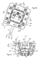
- FIG. 1 there is shown a box 100 for embedding an electrical equipment 300, 400 in any wall.
- this box is a box claw fixing, intended to be embedded in a hollow wall as a honeycomb wall.
- it may be a box secured by gluing in a hollow wall or a wall of plaster or a box to be sealed in a concrete wall.
- this box 100 comprises a bottom 101 which delimits, at the rear, an interior space for receiving a base 310 of apparatus mechanism 300 (see FIG. figure 11 ).
- This interior space is delimited laterally by a side wall 102, here a cylindrical wall which borders the circular base 101.
- the side wall 102 rises perpendicular to the bottom 101. It is connected here to the bottom 101 by a rounded so that there is a continuity without edge or break between the bottom 101 and the side wall 102 of the box 100.
- the box 100 is open to receive the equipment mechanism 300.
- the front opening of the box 100 is bordered by a flange 103 having ears 104 regularly distributed around the periphery of said box 100 and advantageously intended for bear against the front face of the wall (not shown).
- the inner face 102B of the side wall 102 of the box 100 carries two diametrically opposed wells 105 adapted to receive screws (not shown) for actuating claws (not shown) housed in housings provided in recess of the outer face 102A of said side wall 102.
- the screwing of the screws (not shown) in the corresponding wells 105 of the box 100 causes, at first, the output of the claws (not shown) of their housing to project them from the external face 102A of the side wall 102 of the box 100, and, in a second step, the displacement of said claws projecting along the threaded bodies of said screws to come and block them against the rear face of the recess wall (not shown).
- the bottom 101 is provided with an opening 110 intended to receive, from the rear of said box, an electrical connector 200 so that a part 230 of this connector emerges in said inner space of the box 100 (see figures 4 and 8 ).
- the electrical connector 200 is shown which, according to the invention, is particularly adapted to the box 100.
- This electrical connector 200 comprises, on the one hand, an insulating envelope which forms in one piece, at the rear, a sleeve 210 of axis X receiving an end of an electric cable 10 and, at before, a terminal block 230 which generally extends substantially along an axis Y perpendicular to the axis X of said sleeve 210.
- the sleeve 210 internally comprises three parallel conduits 212, isolated from each other, which are intended to receive the cores devoid of the three conductors 11, 12, 13 of phase, neutral and earth of the electric cable 10.
- the terminal block 230 is a parallelepipedal insulating block which comprises three parallel conduits 231, extending along the axis Y perpendicular to the axis X of the sleeve 210. These conduits 231 open out of said insulating envelope of the electrical connector. 200 and communicate inside said insulating envelope with the conduits 212 of the sleeve 210.
- the conduits 231 of the terminal block 230 house conductive strips 21, 22, 23 made of metallic material.
- One end 31, 32, 33 of each conductive blade 21, 22, 23 is accessible via one of the conduits 212 of the sleeve 210 so that the stripped core of each conductor 11, 12, 13 of the electrical cable 10 fitted into said sleeve 210, comes into contact with a conductive blade 21, 22, 23 of the terminal block 230.
- the bottom 101 includes retaining means 130 adapted to bind said electrical connector 200 to the bottom 101 while allowing a displacement of said electrical connector 200 in said opening 110 relative to the bottom 101.
- One of the displacements authorized by said retaining means 130 provided on the box 100 is a displacement in a plane parallel to the plane formed by said bottom 101 (see FIG. figures 4 and 7 ). This is a pivot about an axis R perpendicular to the plane formed by said bottom 101.
- Another displacement authorized by said retaining means 130 of the box 100 is a translation along a perpendicular direction (axis R) to the plane formed by said bottom 101 (see FIG. figures 5 and 14 ).
- the electrical connector 200 comprises mounting means 220, provided on the outer face 211 of the sleeve 210, adapted to cooperate with said retaining means 130 of the box 100 for mounting said electrical connector 200 on the outer face 101A of the bottom 101 of said box 100 such that said terminal 230 emerges, via said opening 110 provided in the bottom 101 of the box 100, in the interior space of said box (see Figures 4 to 6 ).
- said retaining means 130 of the box 100 comprise at least one female element placed near an edge 111 of said opening 110 and adapted to receive a male element 220 provided on said electrical connector 200 .
- the female element of the box 100 is an orifice 130 passing through the bottom 101 of said box 100.
- the orifice 130 is a circular orifice.
- said mounting means 220 of the electrical connector 200 comprise a male element which here comprises two tabs 221 parallel to the Y axis perpendicular to the X axis of said sleeve 210. These tabs 221 comprise two outer faces turned opposite each other which carry, near the free end of said tabs, a hooking tooth 222. In addition, said tabs 221 have a base secured to a rigid pad 223.
- the circular section of the rigid pad 223 surmounted by the tabs 221 has a diameter equal to the clearance close to the diameter of the circular orifice 130 of the box 100, the attachment teeth 222 extending outside this circular section.
- the height taken from the base of the rigid pad 223 secured to the outer face 211 of the sleeve 210 to the attachment face of the attachment teeth 222 is of the order of 5 millimeters.
- the mounting of the electrical connector 200 on the outer face 101A of the bottom 101 of the box 100 is effected by forcibly engaging the tabs 221 of said mounting means 220 through the circular hole 130 of the box 100.
- said tabs 221 slightly bend toward each other to allow the passage of the attachment teeth 222 through the hole 130 of the bottom 101 of the box 100.
- the attachment teeth 222 comprise an outer sloping section which slides against the edge of said orifice 130 and which gradually causes the bending towards each other of said tabs 221.
- the terminal block 230 of the electrical connector 200 emerges in the interior of the box 100 through the opening 110 provided in the bottom 101.
- the terminal 230 extends along the Y axis perpendicular to the bottom 101 of the box 100, parallel to the pivot axis R of said electrical connector 200 (see figure 8 ).
- This axis R corresponds to the axis of the rigid stud 223 of circular section (see figure 6 ).
- the rigid pad 223 forms a pivot pin in said orifice 130 to allow the electrical connector 200 to move in said opening 110 parallel to the plane of the bottom 101 of the box 100.
- the electrical connector 200 can then take several angular positions determined around the R axis (see figures 4 and 7 ).
- the electrical connector 200 can then take several positions parallel to the plane of the outer face 101A of the bottom 101. These positions are between two extreme positions.
- the first extreme position represented on the Figures 5 and 6 , is the position in which the sleeve 210 of the electrical connector 200 is pressed against the outer face 101A of the bottom 101 of the box 100.
- the second extreme position is the position in which the attachment teeth 222 of the mounting means 220 of the electrical connector 200 bear against the inner face 101 B of the bottom 101 of the box 100 on the edge of the orifice 130 in order to retain the connector 200 on the box 100.
- the distance between the two extreme positions is equal to about 5 millimeters.
- the latter comprises locking means 121 of the electrical connector 200 in a determined position relative to the base 101.
- said retaining means 130 and said blocking means 121 of the box 100 are distinct from each other.
- the locking means comprise at least one groove 121 disposed on an edge 112 of said opening 110 of the bottom 101, adapted to receive a rib 241 provided projecting on said electrical connector 200.
- grooves 121 aligned in a circular arc and spaced from each other by an angle of about 20 degrees.
- Each groove 121 of the box 100 is advantageously formed hollow in a guide wall 120 provided on said bottom 101, inside said box 100, along at least a portion of the edge 112 of said opening 110 to guide said electrical connector 200 during its displacement.
- the opening 110 provided in the bottom 101 of the box 100 has an edge 112 in an arc along which are disposed said locking means.
- the guide wall 120 extends along this edge 112 in an arc and has recessed on its face facing said opening 110 the two grooves 121 blocking.
- the electrical connector 200 comprises locking means 241 for locking it in a determined position in said opening 110 of the bottom 101 of said box 100.
- said retaining means 220 and said locking means 241 are distinct from one another.
- said locking means of the electrical connector 200 comprise at least one rib 241 provided as a projection of a guide wall 240 disposed in front of said terminal block 230, along the latter.
- This guide wall 240 projects two ribs 241 aligned in an arc of a circle and spaced from each other by an angle equal to about 20 degrees.
- Each of these ribs 241 is adapted to be wedged by sliding in one of the grooves 121 provided in correspondence in said guide wall 120 of the box 100 (see FIG. figure 9 ).
- the guide wall 240 of the electrical connector 200 extends along an arc of a circle.
- the guide walls 120, 240 of the box 100 and the electrical connector 200 extend along the same arc because they are intended to slide on one another during the pivoting of the electrical connector. 200 in the opening 110 of the box 100 to guide said connector in its movement and prevent any parasitic movement.
- the electrical connector 200 is mounted on the outer face 101A of the bottom 101 of the box 100, so as to center the terminal block 230 on a diameter X1 of the box 100 (see figure 4 ). Then, it can be rotated to the right, according to the arrow F on the figure 4 at an angle A1 of about 20 degrees (here equal to 19.5 degrees) about the axis R to bring the terminal block 230 in a determined position, centered on another diameter X2 of the box 100. In this second position, said electrical connector 200 is temporarily blocked on the bottom 101 by wedging its ribs 241 in the corresponding grooves 121 of the box 100.
- the electrical connector 200 is adapted to be connected to an equipment mechanism 300 specially adapted for such a fast connection and reported in the inner space of the box 100.
- the box 100 has on the inner face 102B of its side wall 102, on either side of the opening 110 of its bottom 101, two wells 140 with an elongate section for screwing screws V for fixing a apparatus support 400 to be brought to the front of said box 100 (see figures 10 and 13 ).
- such an equipment support 400 is conventionally in the form of a frame of small thickness, whose inner edge 401 delimits a central opening, here of square shape, intended to receive the base 310 isolating the gear mechanism 300 (see figure 11 ).
- the equipment support 400 comprises, along at least a portion of its inner edge 401, a rib 402 which projects from the side of the rear face of the support facing the inner space of the box 100.
- This rib 402 serves for hooking the base 310 of the fitting mechanism 300 by means of engaging teeth 311 and a counter-flange 312 provided on the base 310 (see FIG. figure 12 ).
- the equipment support 400 also comprises, in a conventional manner, in each of its branches, latching means 403 of a finishing plate (not shown).
- the equipment mechanism 300 is here a plug-in mechanism, but it could be a switch mechanism or a reciprocating mechanism.
- This equipment mechanism 300 comprises an insulating base 310 enclosing conductive clips 301 forming pin receiving cells of an electrical plug (not shown).
- the base 310 also houses the foot of a ground pin 302 which emerges in the receiving well of the socket formed by a hubcap attached to the base 310.
- the base 310 of this equipment mechanism 300 comprises, at the rear, receiving means 320 of the terminal block 230 of the electrical connector 200 described above (see FIG. figures 11 and 12 ).
- these receiving means comprise a housing 320 for receiving said terminal block 230.
- the housing 320 is defined inside a parallelepiped cassette whose dimensions are adjusted to those of the parallelepiped block of the terminal block 230. This housing 320 is delimited laterally by side walls 321 and is open towards the rear of the base 310 to allow the introduction of the terminal block 230 inside thereof.
- the direction of insertion of the terminal block 230 of the electrical connector 200 in the housing 320 of the base 310 of the equipment mechanism 300 is the direction of the Z axis of the receiving well of the socket according to which extends the pin of 302.
- This axis Z is also the axis in which the base 310 of the equipment mechanism 300 is introduced into the box 100.
- This axis Z is parallel to the axis Y along which the ducts 231 of the terminal block 230 extend. of the electrical connector 200.
- the conductive clamps 301 and the grounding pin 302 of the switchgear mechanism 300 are each connected to a flat conductive pin 305 which extends into said housing 320 along the Z axis (see FIG. figure 11 ).
- Said flat conductive pins 305 are arranged in such a way that they are introduced into the corresponding conduits 231 of the terminal block 230 when the latter is engaged in said housing 320 of the base 310 of the equipment mechanism 300 in order to establish an electrical contact with the conductive strips 21, 22, 23 of the terminal block 230.
- said receiving means 320 of the base 310 comprise guide means 322 for sliding said terminal block 230.
- These guiding means comprise two grooves 322 provided facing the inside face of two of the parallel side walls 321 of said base cassette 310 of the fitting mechanism 300.
- These two grooves 322 extend parallel to the Z axis of the receiving well of the equipment mechanism 300.
- said terminal block 230 of the electrical connector 200 comprises on two parallel lateral sides 230A, two ribs 232 arranged to slide in the grooves 322 of the base 310 of the fitting mechanism 300 (see FIG. figure 12 ).
- the terminal block 230 of the electrical connector 200 is correctly guided in the receiving housing 320 of the base 310 of the fitting mechanism 300 so that said flat conductive pins 305 connected to the electrical components of the switchgear mechanism 300 engage without jamming in the corresponding conduits 231 of the terminal block 230.
- the terminal block 230 comprises hooking means 233 adapted to cooperate with complementary hooking means provided at the rear of the base 310 of the equipment mechanism 300.
- Said attachment means of the base 310 comprise a attachment tooth (not visible in the figures) adapted to catch on an edge of a window 233 provided on a longitudinal wall 230B of the terminal block 230.
- the insulating envelope of the electrical connector 200 forms, in front of said terminal block 230, another terminal block 250, called a transiting terminal, which extends along the axis X of said sleeve 210 in extension thereof.
- Said crossover terminal 250 is a block which comprises several (here three) conduits 251 parallel to each other, extending along the axis X of said sleeve. These ducts 251 open out of said insulating casing and communicate with the inside of said sleeve 210.
- Each duct 251 of the transponding terminal block 250 houses a conductive blade 40 which is electrically connected to a conductive blade 21, 22, 23 of FIG. a conduit 231 of the first terminal block 230 accessible via a conduit 212 of said sleeve 210.
- an installer can electrically connect another electrical equipment to said electrical connector 200 attached to the outer face 101A of the bottom 101 of said box 100. It is sufficient that it introducing the stripped cores of the conductors of an electric cable supplying said apparatus, into the conduits 251 of said transiting terminal block 250 so that they come into contact with the conductive strips 40.
- the box 100 is advantageously made in one piece by molding a synthetic material.
- the insulating jacket of the electrical connector 200 is advantageously made by molding a synthetic material.
- the base 310 of the equipment mechanism 300 provided with its receiving means is advantageously made in one piece by molding a synthetic material.
- the electrical connector 200 is previously fitted on the electrical cable 10 of the supply network so that the stripped cores of its conductors 11, 12, 13 are introduced into the conduits 212 of the sleeve 210 and placed in contact with the ends 31, 32, 33 conductive blades 21, 22, 23.
- the electrical connector 200 is assembled from the back to the box 100, before it is embedded in the recessed hole (not shown) formed in the recessed wall (not shown).
- the electrical connector 200 is mounted on the outer face 101A of the bottom 101 of the box 100, so as to center the terminal block 230 on a diameter X1 of the box 100 (see figure 4 ).
- the electrical connector 200 is mounted by forcibly engaging the tabs 221 of its mounting means 220 through the circular orifice 130 of the box 100.
- the terminal block 230 of the electrical connector 200 emerges in the interior of the box 100 through the opening 110 provided in the bottom 101.
- the terminal 230 extends perpendicular to the bottom 101 of the box 100 , parallel to the axis R of pivoting of said electrical connector 200.
- the rigid pad 223 forms a pivot pin in said orifice 130 to allow the electrical connector 200 to move in said opening 110 parallel to the plane of the bottom 101 of the box 100.
- the electrical connector 200 can then take several angular positions determined around the R axis (see figures 4 and 7 ).
- the electrical connector 200 is pivoted to the right, according to the arrow F on the figure 4 at an angle A1 of about 20 degrees (here equal to 19.5 degrees) about the axis R, to bring the terminal block 230 in a determined position, centered on another diameter X2 of the box 100.
- the electrical connector 200 is temporarily blocked on the bottom 101 by wedging its ribs 241 in the corresponding grooves 121 of the box 100.
- the electrical connector 200 is adapted to be connected to the equipment mechanism 300.
- the box 100 equipped with the electrical connector 200 temporarily blocked, is embedded in the recessing hole provided in the recess wall so that its lugs 104 bear against the front face of said recess wall.
- the base 310 of the equipment mechanism 300 mounted in the central opening of the equipment support 400 is then returned into the interior of the box 100 recessed, along the Z axis of the receiving well of the socket .
- the housing 320 of the base 310 is engaged on the terminal block 230 of the electrical connector 200 so that the ribs 232 of the terminal block 230 slide in the corresponding grooves 322 of the base 310 until the attachment tooth of the base 310 catches on the edge of the window 233 of the terminal block 230.
- the equipment mechanism 300 is electrically connected to the electrical connector 200.
- the equipment support 400 equipped with the equipment mechanism 300 electrically connected to the electrical connector 200, is offset by an angle of about 20 degrees (equal to 19.5 degrees) relative to the horizontal H.
- the rear face of the equipment support 400 is placed at a distance D of about 5 millimeters above the edge 103 of the box 100 recessed.
- the equipment support 400 equipped with the equipment mechanism 300 is then rotated according to the arrow F1 (on the figure 10 ) about the axis R, to release the ribs 241 of the electrical connector 200 of the grooves 121 of the box 100 and make free movement of said electrical connector 200 in the opening 110 of the box to adjust the position of the support of apparatus 400 on the horizontal H (see figure 13 ).
- the equipment support 400 and the equipment mechanism 300 are driven into said box 100 until the rear face of the equipment support 400 bears against the flange 103 of the box 100 or against a possible coating (upholstery or carpet) placed in excess on the front face of the wall.
- the terminal block 230 of the electrical connector 200 is pushed towards the outside of the box 100, and the rigid pad 223 is slid into said orifice 130 along its axis R perpendicular to the plane of the bottom 101.
- the outer face 211 of the sleeve 210 of the electrical connector 200 is no longer in contact with the face external 101A of the bottom 101 of said box 100 and the electrical connector 200 then takes a position parallel to the plane of the outer face 101A of the bottom 101, shown on the figures 14 and 15 , in which the hooking teeth 222 of the mounting means 220 of the electrical connector 200 bear against the inner face 101B of the bottom 101 of the box 100 on the edge of the orifice 130 in order to retain the electrical connector 200 on the box 100.
- This retention of the electrical connector 200 on the box 100 is particularly advantageous because an installer can subsequently intervene on the electrical assembly to disassemble the equipment mechanism 300 to repair or change without losing the electrical connector 200 in the hollow portion of the flush wall.
- the elongated (here oblong) section of these wells 140 makes it possible to adjust the angular position of the equipment support 400 on said box 100 as described above, while leaving the screws V linked to said support.
- the displacement of the electrical connector, authorized by said retaining means of the box is a translation.
- said box retaining means could comprise grooves which border two opposite edges of said opening.
- said retaining means comprise a male element placed near an edge of said opening and adapted to receive a female element provided on said electrical connector.
- said terminal comprises, in place of the parallelepiped block with hollow ducts, a parallelepipedal housing which houses several pins parallel to each other, this housing opening out of said insulating casing and communicating therewith with said sleeve.
- Said male element provided on the electrical connector may comprise at least one rib adapted to slide in a groove of the flush-mounting box.
- said means for mounting the electrical connector on said box may comprise a female element adapted to receive a male element provided on the flush-mounting box.
Abstract
Description
La présente invention concerne de manière générale le raccordement électrique au réseau des appareillages électriques encastrés.The present invention generally relates to the electrical connection to the network of built-in electrical equipment.
Elle concerne plus particulièrement une boîte d'encastrement d'un appareillage électrique, comprenant un fond qui délimite, à l'arrière, un espace intérieur de réception d'un socle de mécanisme d'appareillage, ce fond étant pourvu d'une ouverture destinée à accueillir, par l'arrière de ladite boîte, un connecteur électrique de sorte qu'une partie de ce connecteur émerge dans ledit espace intérieur.It relates more particularly to a flush-mounting box of an electrical apparatus, comprising a bottom which delimits, at the rear, an interior space for receiving a base of an equipment mechanism, this bottom being provided with an opening intended to receiving, from the rear of said box, an electrical connector so that a portion of this connector emerges in said interior space.
Elle concerne également un connecteur électrique à emmancher sur une extrémité d'un câble électrique d'alimentation, spécialement adapté à la boîte d'encastrement précitée ainsi qu'un mécanisme d'appareillage destiné à recevoir ce connecteur électrique.It also relates to an electrical connector to be fitted on one end of an electric supply cable, specially adapted to the aforementioned mounting box and an equipment mechanism for receiving this electrical connector.
Elle concerne enfin un ensemble électrique comprenant une telle boîte électrique, un tel connecteur électrique ainsi qu'un tel mécanisme d'appareillage.Finally, it relates to an electrical assembly comprising such an electrical box, such an electrical connector and such an equipment mechanism.
L'invention trouve une application particulièrement avantageuse dans la réalisation d'un système électrique à connexion rapide au réseau électrique.The invention finds a particularly advantageous application in the realization of an electrical system with fast connection to the electrical network.
On connaît déjà du document
Selon ce document, la connexion électrique entre lesdits composants électriques du mécanisme d'appareillage est réalisée soit par l'intermédiaire de conducteurs électriques souples, soit par l'enfichage dans ledit connecteur intermédiaire d'un connecteur complémentaire prévu à l'arrière du mécanisme.According to this document, the electrical connection between said electrical components of the equipment mechanism is achieved either by means of flexible electrical conductors, or by plugging into said intermediate connector of a complementary connector provided at the rear of the mechanism.
La connexion par l'intermédiaire de conducteurs souples est longue et fastidieuse à réaliser. En outre, elle ne présente pas un haut niveau de sécurité.The connection via flexible conductors is long and tedious to achieve. In addition, it does not have a high level of security.
Dans le cas où la connexion entre le mécanisme d'appareillage et le connecteur intermédiaire est réalisée via l'enfichage d'un connecteur prévu sur le mécanisme d'appareillage, le montage fixe par encliquetage du connecteur intermédiaire dans l'ouverture rectangulaire du fond de la boîte d'encastrement impose la manière dont le mécanisme d'appareillage doit être positionné dans ladite boîte pour que son connecteur puisse coopérer correctement avec ledit connecteur intermédiaire. Ce montage fixe empêche alors un installateur d'ajuster la position du mécanisme d'appareillage dans ladite boîte pour rattraper un défaut d'orientation par rapport à l'horizontale de la boîte dans le trou d'encastrement (rattrapage d'aplomb) ou pour ajuster l'enfoncement du mécanisme d'appareillage dans ladite boîte afin d'appuyer correctement le support du mécanisme d'appareillage contre la face avant de la boîte d'encastrement ou contre la face avant de la paroi d'encastrement (rattrapage de profondeur).In the case where the connection between the switchgear mechanism and the intermediate connector is made via the plugging of a connector provided on the switchgear mechanism, the fixed mounting snap of the intermediate connector in the rectangular opening of the bottom of the flush-mounting box imposes the manner in which the equipment mechanism must be positioned in said box so that its connector can cooperate correctly with said intermediate connector. This fixed assembly then prevents an installer from adjusting the position of the equipment mechanism in said box to make up for a defect of orientation relative to the horizontal of the box in the mounting hole (catching up) or for adjusting the insertion of the fitting mechanism into said box in order to correctly support the support of the equipment mechanism against the front face of the recess box or against the front face of the recess wall (depth retrofit) .
Afin de remédier aux inconvénients précités de l'état de la technique précité, la présente invention propose une boîte d'encastrement telle que définie dans la revendication 1,In order to overcome the aforementioned drawbacks of the above-mentioned state of the art, the present invention proposes a flush-mounting box as defined in
Ainsi, avantageusement grâce à l'invention, un éventuel défaut d'orientation par rapport à l'horizontale ou un éventuel défaut d'enfoncement de ladite boîte d'encastrement dans son trou d'encastrement peut être facilement rattrapé par un installateur lors du montage dans ladite boîte d'un socle de mécanisme d'appareillage.Thus, advantageously thanks to the invention, a possible defect of orientation relative to the horizontal or a possible defect of embedding said recess box in its mounting hole can be easily caught by an installer during assembly in said box of an apparatus mechanism base.
En effet, grâce auxdits moyens de retenue particuliers de la boîte d'encastrement conforme à l'invention qui autorisent un déplacement par rapport à son fond du connecteur électrique rapporté par l'arrière dans ladite ouverture, un installateur peut de manière simple et rapide enficher un connecteur appartenant au mécanisme d'appareillage sur ledit connecteur électrique lié à ladite boîte, puis il peut ajuster la position du mécanisme d'appareillage lié audit connecteur électrique dans ladite boîte en déplaçant ce dernier par rapport au fond de ladite boîte pour effectuer les rattrapages d'aplomb ou de profondeur nécessaires au bon positionnement de l'appareillage électrique dans la paroi d'encastrement.Indeed, thanks to said particular retaining means of the flush-mounting box according to the invention which allow a displacement relative to its bottom of the electrical connector reported by the rear in said opening, an installer can simply and quickly plug a connector belonging to the fitting mechanism on said electrical connector connected to said box, then it can adjust the position of the fitting mechanism connected to said electrical connector in said box by moving the latter relative to the bottom of said box to make the catch-ups plumb or depth necessary for the proper positioning of the electrical equipment in the flush wall.
D'autres caractéristiques non limitatives et avantageuses de la boîte d'encastrement conforme à l'invention sont énoncées dans les revendications 2 à 16.Other non-limiting and advantageous features of the flush-mounting box according to the invention are set forth in claims 2 to 16.
L'invention concerne également un connecteur électrique selon la revendication 17.The invention also relates to an electrical connector according to claim 17.
D'autres caractéristiques non limitatives et avantageuses du connecteur électrique selon l'invention sont énoncées dans les revendications 18 à 33.Other non-limiting and advantageous features of the electrical connector according to the invention are set forth in claims 18 to 33.
L'invention concerne également un mécanisme d'appareillage qui comporte un socle isolant renfermant des composants électriques et comprenant à l'arrière des moyens de réception du bornier du connecteur électrique selon l'invention.The invention also relates to an apparatus mechanism which comprises an insulating base enclosing electrical components and comprising at the rear means for receiving the terminal block of the electrical connector according to the invention.
D'autres caractéristiques non limitatives et avantageuses du mécanisme d'appareillage selon l'invention sont énoncées dans les revendications 35 à 41.Other non-limiting and advantageous features of the fitting mechanism according to the invention are set forth in claims 35 to 41.
Enfin l'invention concerne un ensemble électrique à connexion rapide, comprenant :
- une boîte d'encastrement selon l'invention,
- un connecteur électrique selon l'invention emmanché sur une extrémité d'un câble électrique d'alimentation, à rapporter par l'arrière de ladite boîte d'encastrement dans ladite ouverture dudit fond de telle manière que ledit connecteur est retenu sur la face externe dudit fond par la coopération des moyens de montage dudit connecteur avec lesdits moyens de retenue de ladite boîte, et
- un mécanisme d'appareillage selon l'invention dont le socle est adapté, d'une part, à être monté sur un support d'appareillage à rapporter à l'avant de ladite boîte d'encastrement, et, d'autre part, à être engagé dans l'espace intérieur de ladite boîte d'encastrement de façon à recevoir à l'arrière ledit bornier du connecteur électrique.
- a flush-mounting box according to the invention,
- an electrical connector according to the invention fitted on one end of an electric supply cable, to be brought from the back of said embedding box into said opening of said bottom so that said connector is retained on the outer face of said bottom by the cooperation of the mounting means of said connector with said retaining means of said box, and
- an apparatus mechanism according to the invention, the base of which is adapted, on the one hand, to be mounted on an equipment support to be brought to the front of said mounting box, and, on the other hand, to to be engaged in the interior space of said flush-mounting box so as to receive said terminal block of the electrical connector at the rear.
La description qui va suivre en regard des dessins annexés, donnée à titre d'exemple non limitatif, fera bien comprendre en quoi consiste l'invention et comment elle peut être réalisée.The following description with reference to the accompanying drawings, given by way of non-limiting example, will make it clear what the invention is and how it can be achieved.
Sur les dessins annexés :
- la
figure 1 est une vue schématique en perspective de dessus d'une boîte d'encastrement conforme à l'invention ; - la
figure 2 est une vue schématique en perspective d'un connecteur électrique conforme à l'invention, emmanché sur l'extrémité d'un câble électrique ; - la
figure 3 est une vue schématique en perspective du connecteur de lafigure 2 ; - la
figure 4 est une vue schématique de face de la boîte d'encastrement de lafigure 1 sur le fond de laquelle est monté le connecteur électrique de lafigure 3 ;' - la
figure 5 est une vue en coupe selon le plan B-B de lafigure 4 ; - la
figure 6 est une vue du détail C de lafigure 5 ; - la
figure 7 est une vue schématique de face de la boîte d'encastrement de lafigure 1 sur le fond de laquelle est bloqué dans une position déterminée le connecteur électrique de lafigure 3 ; - la
figure 8 est une vue en coupe selon le plan A-A de lafigure 7 ; - la
figure 9 est une vue du détail D de lafigure 8 ; - la
figure 10 est une vue schématique de face d'un mécanisme d'appareillage selon l'invention, monté sur un support d'appareillage rapporté à l'avant de la boîte d'encastrement de lafigure 7 ; - la
figure 11 est une vue en coupe selon le plan C-C de lafigure 10 ; - la
figure 12 est une vue en coupe selon le plan D-D de lafigure 10 ; - la
figure 13 est une vue schématique de face du mécanisme d'appareillage de lafigure 10 dont l'orientation par rapport à l'horizontale et dont l'enfoncement dans ladite boîte d'encastrement ont été ajustés après avoir été connecté audit connecteur électrique rapporté sur le fond de la boîte ; - la
figure 14 est une vue en coupe selon le plan E-E de lafigure 13 ; et - la
figure 15 est une vue du détail B de lafigure 14 .
- the
figure 1 is a schematic perspective view from above of a flush-mounting box according to the invention; - the
figure 2 is a schematic perspective view of an electrical connector according to the invention, fitted on the end of an electric cable; - the
figure 3 is a schematic perspective view of the connector of thefigure 2 ; - the
figure 4 is a schematic front view of the flush-mounting box of thefigure 1 on the bottom of which is mounted the electrical connector of thefigure 3 ; ' - the
figure 5 is a sectional view along the plane BB of thefigure 4 ; - the
figure 6 is a detail view C of thefigure 5 ; - the
figure 7 is a schematic front view of the flush-mounting box of thefigure 1 on the bottom of which is blocked in a certain position the electrical connector of thefigure 3 ; - the
figure 8 is a sectional view according to the plane AA of thefigure 7 ; - the
figure 9 is a detail view D of thefigure 8 ; - the
figure 10 is a schematic front view of an equipment mechanism according to the invention, mounted on an equipment support attached to the front of the flush mounting box of thefigure 7 ; - the
figure 11 is a sectional view along the plane CC of thefigure 10 ; - the
figure 12 is a sectional view along the plane DD of thefigure 10 ; - the
figure 13 is a schematic front view of the fitting mechanism of thefigure 10 whose orientation relative to the horizontal and whose depression in said recess box have been adjusted after being connected to said electrical connector attached to the bottom of the box; - the
figure 14 is a sectional view according to the EE plan of thefigure 13 ; and - the
figure 15 is a detail view B of thefigure 14 .
Sur la
Ici, cette boîte est une boîte à fixation par griffes, destinée à être encastrée dans une paroi creuse comme une paroi alvéolaire.Here, this box is a box claw fixing, intended to be embedded in a hollow wall as a honeycomb wall.
En variante, il peut s'agir d'une boîte solidarisée par collage dans une paroi creuse ou une paroi de plâtre ou encore une boîte à sceller dans une paroi béton.Alternatively, it may be a box secured by gluing in a hollow wall or a wall of plaster or a box to be sealed in a concrete wall.
De manière classique, cette boîte 100 comporte un fond 101 qui délimite, à l'arrière, un espace intérieur de réception d'un socle 310 de mécanisme d'appareillage 300 (voir
La paroi latérale 102 s'élève perpendiculairement au fond 101. Elle se raccorde ici au fond 101 par un arrondi de sorte qu'il y a une continuité sans arête ni cassure entre le fond 101 et la paroi latérale 102 de la boîte 100.The
À l'avant, la boîte 100 est ouverte pour recevoir le mécanisme d'appareillage 300. L'ouverture avant de la boîte 100 est bordée par un rebord 103 comportant des oreilles 104 régulièrement réparties sur le pourtour de ladite boîte 100 et destinées avantageusement à prendre appui contre la face avant de la paroi d'encastrement (non représentée).At the front, the
La face intérieure 102B de la paroi latérale 102 de la boîte 100 porte deux puits 105 diamétralement opposés adaptés à recevoir des vis (non représentées) d'actionnement de griffes (non représentées) logées dans des logements prévus en renfoncement de la face externe 102A de ladite paroi latérale 102.The
De manière usuelle, le vissage des vis (non représentées) dans les puits 105 correspondants de la boîte 100 provoque, dans un premier temps, la sortie des griffes (non représentées) de leur logement pour les placer en saillie de la face externe 102A de la paroi latérale 102 de la boîte 100, et, dans un deuxième temps, le déplacement desdites griffes en saillie le long des corps filetés desdites vis pour venir les bloquer contre la face arrière de la paroi d'encastrement (non représentée).In the usual way, the screwing of the screws (not shown) in the corresponding
Selon une caractéristique particulièrement avantageuse de la boîte 100 conforme à l'invention, le fond 101 est pourvu d'une ouverture 110 destinée à accueillir, par l'arrière de ladite boîte, un connecteur électrique 200 de sorte qu'une partie 230 de ce connecteur émerge dans ledit espace intérieur de la boîte 100 (voir
Sur les
Ce connecteur électrique 200 comprend, d'une part, une enveloppe isolante qui forme d'une seule pièce, à l'arrière, un manchon 210 d'axe X de réception d'une extrémité d'un câble électrique 10 et, à l'avant, un bornier 230 qui s'étend globalement sensiblement selon un axe Y perpendiculaire à l'axe X dudit manchon 210.This
Comme le montre plus particulièrement la
Le bornier 230 est un bloc isolant parallélépipédique qui comprend trois conduits 231 parallèles entre eux, s'étendant selon l'axe Y perpendiculaire à l'axe X du manchon 210. Ces conduits 231 débouchent à l'extérieur de ladite enveloppe isolante du connecteur électrique 200 et communiquent à l'intérieur de ladite enveloppe isolante avec les conduits 212 du manchon 210.The
Les conduits 231 du bornier 230 logent des lames conductrices 21, 22, 23 en matière métallique. Une extrémité 31, 32, 33 de chaque lame conductrice 21, 22, 23 est accessible via l'un des conduits 212 du manchon 210 de sorte que l'âme dénudée de chaque conducteur 11, 12, 13 du câble électrique 10 emmanché dans ledit manchon 210, vient au contact d'une lame conductrice 21, 22, 23 du bornier 230.The
Selon une caractéristique essentielle de la boîte 100, le fond 101 comporte des moyens de retenue 130 adaptés à lier ledit connecteur électrique 200 au fond 101 tout en autorisant un déplacement dudit connecteur électrique 200 dans ladite ouverture 110 par rapport à ce fond 101.According to an essential characteristic of the
Un des déplacements autorisés par lesdits moyens de retenue 130 prévus sur la boîte 100 est un déplacement dans un plan parallèle au plan formé par ledit fond 101 (voir
Un autre déplacement autorisé par lesdits moyens de retenue 130 de la boîte 100 est une translation suivant une direction perpendiculaire (axe R) au plan formé par ledit fond 101 (voir
En correspondance, le connecteur électrique 200 comporte des moyens de montage 220, prévus sur la face externe 211 du manchon 210, adaptés à coopérer avec lesdits moyens de retenue 130 de la boîte 100 pour le montage dudit connecteur électrique 200 sur la face externe 101A du fond 101 de ladite boîte 100 de telle manière que ledit bornier 230 émerge, via ladite ouverture 110 prévue dans le fond 101 de la boîte 100, dans l'espace intérieur de ladite boîte (voir les
Selon l'exemple représenté sur les figures, lesdits moyens de retenue 130 de la boîte 100 comprennent au moins un élément femelle placé à proximité d'un bord 111 de ladite ouverture 110 et adapté à recevoir un élément mâle 220 prévu sur ledit connecteur électrique 200.According to the example shown in the figures, said retaining means 130 of the
Plus particulièrement, l'élément femelle de la boîte 100 est un orifice 130 traversant le fond 101 de ladite boîte 100. Ici, l'orifice 130 est un orifice circulaire.More particularly, the female element of the
Comme le montre plus particulièrement la
La section circulaire du plot rigide 223 surmonté des pattes 221 présente un diamètre égal au jeu près au diamètre de l'orifice 130 circulaire de la boîte 100, les dents d'accrochage 222 s'étendant en dehors de cette section circulaire.The circular section of the
Ici, la hauteur prise à partir de la base du plot rigide 223 solidarisée à la face externe 211 du manchon 210 jusqu'à la face d'accrochage des dents d'accrochage 222 est de l'ordre de 5 millimètres.Here, the height taken from the base of the
Ainsi, comme le montrent les
Lors du montage, lesdites pattes 221 fléchissent légèrement l'une vers l'autre pour permettre le passage des dents d'accrochage 222 au travers de l'orifice 130 du fond 101 de la boîte 100.During assembly, said
Pour faciliter leur introduction au travers de cet orifice 130, les dents d'accrochage 222 comportent un pan incliné extérieur qui glisse contre le bord dudit orifice 130 et qui provoque progressivement le fléchissement l'une vers l'autre desdites pattes 221.To facilitate their introduction through this
Lorsque lesdites dents d'accrochage 222 ont traversé l'orifice 130 du fond 101 de la boîte 100, les pattes 221 reviennent élastiquement dans leur position initiale parallèles l'une à l'autre et le plot rigide 223 prévu à la base des pattes 221 s'engage dans l'orifice 130 jusqu'à ce que la face externe 211 du manchon 210 vienne au contact de la face externe 101A du fond 101 de la boîte 100 (voir
Dans cette position de montage, le bornier 230 du connecteur électrique 200 émerge dans l'espace intérieur de la boîte 100 au travers de l'ouverture 110 prévue dans le fond 101. Le bornier 230 s'étend selon l'axe Y perpendiculairement au fond 101 de la boîte 100, parallèlement à l'axe R de pivotement dudit connecteur électrique 200 (voir
En outre, en poussant le bornier 230 du connecteur électrique 200 vers l'extérieur de la boîte 100, on fait coulisser le plot rigide 223 dans ledit orifice 130, selon son axe R perpendiculaire au plan du fond 101. Le connecteur électrique 200 peut alors prendre plusieurs positions parallèlement au plan de la face externe 101A du fond 101. Ces positions sont comprises entre deux positions extrêmes. La première position extrême, représentée sur les
Selon une caractéristique particulièrement avantageuse de la boîte 100, celle-ci comporte des moyens de blocage 121 du connecteur électrique 200 dans une position déterminée par rapport au fond 101.According to a particularly advantageous characteristic of the
lci, lesdits moyens de retenue 130 et lesdits moyens de blocage 121 de la boîte 100 sont distincts les uns des autres.Here, said retaining means 130 and said blocking means 121 of the
Comme le montrent plus particulièrement les
Ici, il est prévu deux rainures 121 alignées suivant un arc de cercle et espacées l'une de l'autre d'un angle égal à environ 20 degrés.Here, there are two
Chaque rainure 121 de la boîte 100 est avantageusement formée en creux dans une paroi de guidage 120 prévue sur ledit fond 101, à l'intérieur de ladite boîte 100, le long d'au moins une partie du bord 112 de ladite ouverture 110 pour guider ledit connecteur électrique 200 lors de son déplacement.Each
Préférentiellement, l'ouverture 110 prévue dans le fond 101 de la boîte 100 comporte un bord 112 en arc de cercle le long duquel sont disposés lesdits moyens de blocage. La paroi de guidage 120 s'étend le long de ce bord 112 en arc de cercle et comporte en creux sur sa face tournée vers ladite ouverture 110 les deux rainures 121 de blocage.Preferably, the
Comme énoncé ci-dessus, en correspondance des moyens de blocage 121 de la boîte 100, le connecteur électrique 200 comprend des moyens de blocage 241 pour le bloquer dans une position déterminée dans ladite ouverture 110 du fond 101 de ladite boîte 100.As stated above, in correspondence of the blocking means 121 of the
Ici également, dans le connecteur électrique 200, lesdits moyens de retenue 220 et lesdits moyens de blocage 241 sont distincts les uns des autres.Here again, in the
Plus particulièrement, comme le montrent les
Cette paroi de guidage 240 porte en saillie deux nervures 241 alignées suivant un arc de cercle et espacées l'une de l'autre d'un angle égal à environ 20 degrés.This
Chacune de ces nervures 241 est adaptée à être coincée par coulissement dans une des rainures 121 prévue en correspondance dans ladite paroi de guidage 120 de la boîte 100 (voir
Préférentiellement, la paroi de guidage 240 du connecteur électrique 200 s'étend selon un arc de cercle.Preferably, the
En particulier, les parois de guidage 120, 240 de la boîte 100 et du connecteur électrique 200 s'étendent suivant le même arc de cercle car elles sont destinées à glisser l'une sur l'autre lors du pivotement du connecteur électrique 200 dans l'ouverture 110 de la boîte 100 pour guider ledit connecteur dans son déplacement et éviter tout mouvement parasite.In particular, the
Ainsi, avantageusement, comme le montrent les
Dans cette position bloquée, le connecteur électrique 200 est adapté à être connecté à un mécanisme d'appareillage 300 spécialement adapté à une telle connexion rapide et rapporté dans l'espace intérieur de la boîte 100.In this locked position, the
Avantageusement, la boîte 100 comporte sur la face intérieure 102B de sa paroi latérale 102, de part et d'autre de l'ouverture 110 de son fond 101, deux puits 140 à section allongée pour le vissage de vis V de fixation d'un support d'appareillage 400 à rapporter à l'avant de ladite boîte 100 (voir
Comme le montrent les
Le support d'appareillage 400 comporte, le long d'au moins une partie de son bord intérieur 401, une nervure 402 qui fait saillie du côté de la face arrière du support tournée vers l'espace intérieur de la boîte 100. Cette nervure 402 sert à l'accrochage du socle 310 du mécanisme d'appareillage 300 par l'intermédiaire de dents d'accrochage 311 et d'un contre-rebord 312 prévus sur le socle 310 (voir
Le support d'appareillage 400 comporte également, de manière classique, dans chacune de ses branches, des moyens d'encliquetage 403 d'une plaque de finition (non représentée).The
Le mécanisme d'appareillage 300 est ici un mécanisme de prise de courant, mais il pourrait s'agir d'un mécanisme d'interrupteur ou encore d'un mécanisme de va-et-vient.The
Ce mécanisme d'appareillage 300 comporte un socle 310 isolant renfermant des pinces conductrices 301 formant des alvéoles de réception de broches d'une fiche électrique (non représentée). Le socle 310 loge également le pied d'une broche de terre 302 qui émerge dans le puits de réception de la prise de courant formé par un enjoliveur rapporté sur ce socle 310.This
Selon une caractéristique essentielle, le socle 310 de ce mécanisme d'appareillage 300 comprend, à l'arrière, des moyens de réception 320 du bornier 230 du connecteur électrique 200 décrit ci-dessus (voir
Selon le mode de réalisation représenté sur les figures, ces moyens de réception comprennent un logement 320 d'accueil dudit bornier 230.According to the embodiment shown in the figures, these receiving means comprise a
Le logement 320 est défini à l'intérieur d'une cassette parallélépipédique dont les dimensions sont ajustées à celles du bloc parallélépipédique du bornier 230. Ce logement 320 est délimité latéralement par des parois latérales 321 et il est ouvert vers l'arrière du socle 310 pour permettre l'introduction du bornier 230 à l'intérieur de celui-ci.The
La direction d'introduction du bornier 230 du connecteur électrique 200 dans le logement 320 du socle 310 du mécanisme d'appareillage 300 est la direction de l'axe Z du puits de réception de la prise de courant selon lequel s'étend la broche de terre 302. Cet axe Z est également l'axe selon lequel le socle 310 du mécanisme d'appareillage 300 est introduit dans la boîte 100. Cet axe Z est parallèle à l'axe Y selon lequel s'étendent les conduits 231 du bornier 230 du connecteur électrique 200.The direction of insertion of the
Les pinces conductrices 301 et la broche de terre 302 du mécanisme d'appareillage 300 sont chacune reliées à une broche conductrice 305 plate qui s'étend dans ledit logement 320 selon l'axe Z (voir
Lesdites broches conductrices 305 plates sont agencées de manière qu'elles s'introduisent dans les conduits 231 correspondants du bornier 230 lorsque celui-ci est engagé dans ledit logement 320 du socle 310 du mécanisme d'appareillage 300 afin d'établir un contact électrique avec les lames conductrices 21, 22, 23 du bornier 230.Said flat
Avantageusement, lesdits moyens de réception 320 du socle 310 comprennent des moyens de guidage 322 à coulissement dudit bornier 230.Advantageously, said receiving means 320 of the base 310 comprise guide means 322 for sliding said
Ces moyens de guidage comprennent deux rainures 322 prévues en vis-à-vis sur la face intérieure de deux des parois latérales 321 parallèles de ladite cassette du socle 310 du mécanisme d'appareillage 300.These guiding means comprise two
Ces deux rainures 322 s'étendent parallèlement à l'axe Z du puits de réception du mécanisme d'appareillage 300.These two
En correspondance, ledit bornier 230 du connecteur électrique 200 comporte sur deux côtés latéraux 230A parallèles, deux nervures 232 agencées pour coulisser dans les rainures 322 du socle 310 du mécanisme d'appareillage 300 (voir
De cette manière, le bornier 230 du connecteur électrique 200 est correctement guidé dans le logement 320 d'accueil du socle 310 du mécanisme d'appareillage 300 pour que lesdites broches conductrices 305 plates reliées aux composants électriques du mécanisme d'appareillage 300 s'engagent sans coincement dans les conduits 231 correspondants du bornier 230.In this manner, the
Par ailleurs, préférentiellement, le bornier 230 comporte des moyens d'accrochage 233 adaptés à coopérer avec des moyens d'accrochage complémentaires prévus à l'arrière du socle 310 du mécanisme d'appareillage 300. Lesdits moyens d'accrochage du socle 310 comprennent une dent d'accrochage (non visible sur les figures) adaptée à s'accrocher sur un bord d'une fenêtre 233 prévue sur une paroi longitudinale 230B du bornier 230.Furthermore, preferably, the
Enfin, comme le montrent plus particulièrement les
Ledit bornier de repiquage 250 est un bloc qui comprend plusieurs (ici trois) conduits 251 parallèles entre eux, s'étendant suivant l'axe X dudit manchon. Ces conduits 251 débouchent à l'extérieur de ladite enveloppe isolante et communiquent avec l'intérieur dudit manchon 210. Chaque conduit 251 du bornier de repiquage 250 loge une lame conductrice 40 qui est liée électriquement à une lame conductrice 21, 22, 23 d'un conduit 231 du premier bornier 230 accessible via un conduit 212 dudit manchon 210.Said
Grâce au bornier de repiquage 250, un installateur peut connecter électriquement un autre appareillage électrique audit connecteur électrique 200 rapporté sur la face externe 101A du fond 101 de ladite boîte 100. Il suffit qu'il introduise les âmes dénudées des conducteurs d'un câble électrique alimentant ledit appareillage, dans les conduits 251 dudit bornier de repiquage 250 pour que celles-ci viennent au contact des lames conductrices 40.With the plug-in
La boîte 100 est avantageusement réalisée d'une seule pièce par moulage d'une matière synthétique.The
L'enveloppe isolante du connecteur électrique 200 est avantageusement réalisée par moulage d'une matière synthétique.The insulating jacket of the
Enfin, le socle 310 du mécanisme d'appareillage 300 pourvu de ses moyens de réception est avantageusement réalisé d'une seule pièce par moulage d'une matière synthétique.Finally, the
En référence aux
Le connecteur électrique 200 est préalablement emmanché sur le câble électrique 10 du réseau d'alimentation de manière que les âmes dénudées de ses conducteurs 11, 12, 13 soient introduites dans les conduits 212 du manchon 210 et placées au contact des extrémités 31, 32, 33 des lames conductrices 21, 22, 23.The
Puis le connecteur électrique 200 est assemblé par l'arrière à la boîte 100, avant que celle-ci ne soit encastrée dans le trou d'encastrement (non représenté) formé dans la paroi d'encastrement (non représentée).Then the
Plus particulièrement, le connecteur électrique 200 est monté sur la face externe 101A du fond 101 de la boîte 100, de manière à centrer le bornier 230 sur un diamètre X1 de la boîte 100 (voir
Le montage du connecteur électrique 200 s'effectue en engageant à force les pattes 221 de ses moyens de montage 220 au travers de l'orifice 130 circulaire de la boîte 100.The
Lors du montage, les pans inclinés extérieurs des dents d'accrochage 222 portées par lesdites pattes 221 glissent contre le bord dudit orifice 130 et provoquent le fléchissement progressif desdites pattes 221 l'une vers l'autre pour permettre le passage des dents d'accrochage 222 au travers de l'orifice 130 du fond 101 de la boîte 100.During assembly, the outer inclined faces of the
Lorsque lesdites dents d'accrochage 222 ont traversé l'orifice 130 du fond 101 de la boîte 100, les pattes 221 reviennent élastiquement dans leur position initiale parallèles l'une à l'autre et le plot rigide 223 prévu à la base des pattes 221 s'engage dans l'orifice 130 jusqu'à ce que la face externe 211 du manchon 210 vienne au contact de la face externe 101A du fond 101 de la boîte 100.When said
Dans cette position de montage, le bornier 230 du connecteur électrique 200 émerge dans l'espace intérieur de la boîte 100 au travers de l'ouverture 110 prévue dans le fond 101. Le bornier 230 s'étend perpendiculairement au fond 101 de la boîte 100, parallèlement à l'axe R de pivotement dudit connecteur électrique 200.In this mounting position, the
Le plot rigide 223 forme un tourillon de pivotement dans ledit orifice 130 pour autoriser le déplacement du connecteur électrique 200 dans ladite ouverture 110 parallèlement au plan du fond 101 de la boîte 100. Le connecteur électrique 200 peut prendre alors plusieurs positions angulaires déterminées autour de l'axe R (voir
Puis, le connecteur électrique 200 est pivoté vers la droite, selon la flèche F sur la
Dans cette position bloquée, le connecteur électrique 200 est adapté à être connecté au mécanisme d'appareillage 300.In this locked position, the
La boîte 100 équipée du connecteur électrique 200 bloqué temporairement, est encastrée dans le trou d'encastrement prévu dans la paroi d'encastrement de telle manière que ses oreilles 104 appuient contre la face avant de ladite paroi d'encastrement.The
Comme le montrent les
Le logement 320 du socle 310 est engagé sur le bornier 230 du connecteur électrique 200 de manière que les nervures 232 du bornier 230 coulissent dans les rainures 322 correspondantes du socle 310 jusqu'à ce que la dent d'accrochage du socle 310 s'accroche sur le bord de la fenêtre 233 du bornier 230.The
Dans cette position accrochée, les broches conductrices 305 plates du socle 310, reliées aux pinces conductrices 301 et à la broche de terre 302 du mécanisme d'appareillage 300, sont introduites dans les conduits 231 du bornier 230 et sont placées au contact des lames conductrices 21, 22, 23 de ces derniers.In this hooked position, the flat
Le mécanisme d'appareillage 300 est connecté électriquement au connecteur électrique 200.The
Toutefois, dans cette position connectée, comme le montre la
Le support d'appareillage 400 équipé du mécanisme d'appareillage 300 est alors pivoté selon la flèche F1 (sur la
Puis, le support d'appareillage 400 et le mécanisme d'appareillage 300 sont enfoncés dans ladite boîte 100 jusqu'à ce que la face arrière du support d'appareillage 400 vienne en appui contre le rebord 103 de la boîte 100 encastrée ou contre un éventuel revêtement (tapisserie ou moquette) placé en surépaisseur sur la face avant de la paroi d'encastrement.Then, the
Lors de ce mouvement d'ajustement en hauteur du support d'appareillage 400, le bornier 230 du connecteur électrique 200 est poussé vers l'extérieur de la boîte 100, et le plot rigide 223 est coulissé dans ledit orifice 130, selon son axe R perpendiculaire au plan du fond 101. La face externe 211 du manchon 210 du connecteur électrique 200 n'est plus en contact avec la face externe 101A du fond 101 de ladite boîte 100 et le connecteur électrique 200 prend alors une position parallèle au plan de la face externe 101A du fond 101, représentée sur les
Cette retenue du connecteur électrique 200 sur la boîte 100 est particulièrement avantageuse car un installateur peut intervenir ultérieurement sur l'ensemble électrique pour démonter le mécanisme d'appareillage 300 afin de le réparer ou de le changer sans perdre le connecteur électrique 200 dans la partie creuse de la paroi d'encastrement.This retention of the
Finalement, une fois que les ajustements d'aplomb et de profondeur du support d'appareillage 400 ont été réalisés, il ne reste plus qu'à visser les vis V du support d'appareillage 400 dans les puits 140 correspondants de la boîte 100 pour lier ledit support à cette dernière.Finally, once the plumb and depth adjustments of the
La section allongée (ici oblongue) de ces puits 140 permet d'ajuster la position angulaire du support d'appareillage 400 sur ladite boîte 100 comme cela a été décrit ci-dessus, tout en laissant les vis V liées audit support.The elongated (here oblong) section of these
La présente invention n'est nullement limitée au mode de réalisation décrit et représenté, mais l'homme du métier saura y apporter toute variante conforme à son esprit.The present invention is not limited to the embodiment described and shown, but the art can apply any variant within his mind.
Selon une variante non représentée de la boîte conforme à l'invention, on pourrait prévoir que le déplacement du connecteur électrique, autorisé par lesdits moyens de retenue de la boîte, soit une translation.According to a variant not shown of the box according to the invention, it could be provided that the displacement of the electrical connector, authorized by said retaining means of the box, is a translation.
Dans ce cas, lesdits moyens de retenue de la boîte pourraient comprendre des rainures qui bordent deux bords opposés de ladite ouverture.In this case, said box retaining means could comprise grooves which border two opposite edges of said opening.
Selon une autre variante de la boîte non représentée, on pourrait prévoir que lesdits moyens de retenue comprennent un élément mâle placé à proximité d'un bord de ladite ouverture et adapté à recevoir un élément femelle prévu sur ledit connecteur électrique.According to another variant of the box not shown, it could be provided that said retaining means comprise a male element placed near an edge of said opening and adapted to receive a female element provided on said electrical connector.
On pourrait également prévoir, en variante, que ledit bornier comprenne, à la place du bloc parallélépipédique à conduits creux, un logement parallélépipédique qui loge plusieurs broches parallèles entre elles, ce logement débouchant à l'extérieur de ladite enveloppe isolante et communiquant à l'intérieur de celle-ci avec ledit manchon.One could also provide, alternatively, that said terminal comprises, in place of the parallelepiped block with hollow ducts, a parallelepipedal housing which houses several pins parallel to each other, this housing opening out of said insulating casing and communicating therewith with said sleeve.
Ledit élément mâle prévu sur le connecteur électrique peut comprendre au moins une nervure adaptée à coulisser dans une rainure de la boîte d'encastrement.Said male element provided on the electrical connector may comprise at least one rib adapted to slide in a groove of the flush-mounting box.
Enfin, lesdits moyens de montage du connecteur électrique sur ladite boîte peuvent comprendre un élément femelle adapté à recevoir un élément mâle prévu sur la boîte d'encastrement.Finally, said means for mounting the electrical connector on said box may comprise a female element adapted to receive a male element provided on the flush-mounting box.
Claims (42)
Applications Claiming Priority (1)
| Application Number | Priority Date | Filing Date | Title |
|---|---|---|---|
| FR0708468A FR2924535B1 (en) | 2007-12-04 | 2007-12-04 | ELECTRICAL DEVICE RECESSED WITH QUICK CONNECTION |
Publications (1)
| Publication Number | Publication Date |
|---|---|
| EP2068411A1 true EP2068411A1 (en) | 2009-06-10 |
Family
ID=39166381
Family Applications (1)
| Application Number | Title | Priority Date | Filing Date |
|---|---|---|---|
| EP08290989A Withdrawn EP2068411A1 (en) | 2007-12-04 | 2008-10-21 | Embedded electrical appliance with quick connection |
Country Status (2)
| Country | Link |
|---|---|
| EP (1) | EP2068411A1 (en) |
| FR (1) | FR2924535B1 (en) |
Cited By (1)
| Publication number | Priority date | Publication date | Assignee | Title |
|---|---|---|---|---|
| FR3020520A1 (en) * | 2014-04-28 | 2015-10-30 | Legrand France | CONNECTOR FOR ELECTRICAL EQUIPMENT LODGING IN A RECESSED BOX |
Families Citing this family (1)
| Publication number | Priority date | Publication date | Assignee | Title |
|---|---|---|---|---|
| FR2957199B1 (en) | 2010-03-03 | 2015-01-16 | Hager Controls | PRE-EQUIPPED BUILDING DEVICE FOR ELECTRICAL EQUIPMENT |
Citations (3)
| Publication number | Priority date | Publication date | Assignee | Title |
|---|---|---|---|---|
| WO1981002225A1 (en) * | 1980-02-01 | 1981-08-06 | L Denckert | Electric terminal box |
| DE19508552A1 (en) * | 1995-03-10 | 1996-09-12 | Gerhard Glabischnig | Electrical installation multiple socket-outlet in flush or cavity assembly |
| GB2430087A (en) | 2005-09-10 | 2007-03-14 | Schneider Electric Ltd | Mounting box for electrical wiring accessories with pluggable connector |
-
2007
- 2007-12-04 FR FR0708468A patent/FR2924535B1/en not_active Expired - Fee Related
-
2008
- 2008-10-21 EP EP08290989A patent/EP2068411A1/en not_active Withdrawn
Patent Citations (3)
| Publication number | Priority date | Publication date | Assignee | Title |
|---|---|---|---|---|
| WO1981002225A1 (en) * | 1980-02-01 | 1981-08-06 | L Denckert | Electric terminal box |
| DE19508552A1 (en) * | 1995-03-10 | 1996-09-12 | Gerhard Glabischnig | Electrical installation multiple socket-outlet in flush or cavity assembly |
| GB2430087A (en) | 2005-09-10 | 2007-03-14 | Schneider Electric Ltd | Mounting box for electrical wiring accessories with pluggable connector |
Cited By (7)
| Publication number | Priority date | Publication date | Assignee | Title |
|---|---|---|---|---|
| FR3020520A1 (en) * | 2014-04-28 | 2015-10-30 | Legrand France | CONNECTOR FOR ELECTRICAL EQUIPMENT LODGING IN A RECESSED BOX |
| WO2015166170A1 (en) | 2014-04-28 | 2015-11-05 | Legrand France | Connector for an electrical device housed in a recessed box |
| CN106415965A (en) * | 2014-04-28 | 2017-02-15 | 勒格朗法国公司 | Connector for an electrical device housed in a recessed box |
| CN106415965B (en) * | 2014-04-28 | 2018-05-29 | 勒格朗法国公司 | For being contained in the connector of the electrical equipment in embedded case |
| RU2671841C2 (en) * | 2014-04-28 | 2018-11-07 | Легран Франс | Connector for electrical device installed in embedded box |
| US10135231B2 (en) | 2014-04-28 | 2018-11-20 | Legrand France | Connector for an electrical device housed in a recessed box |
| AU2015255088B2 (en) * | 2014-04-28 | 2019-03-14 | Legrand France | Connector for an electrical device housed in a recessed box |
Also Published As
| Publication number | Publication date |
|---|---|
| FR2924535B1 (en) | 2009-12-04 |
| FR2924535A1 (en) | 2009-06-05 |
Similar Documents
| Publication | Publication Date | Title |
|---|---|---|
| EP2936634B1 (en) | Electrical equipment module | |
| WO2014096674A1 (en) | Electrical housing for electrical equipment | |
| WO2015166162A2 (en) | Secured assembly electrical apparatus | |
| FR3020520A1 (en) | CONNECTOR FOR ELECTRICAL EQUIPMENT LODGING IN A RECESSED BOX | |
| EP3138166B1 (en) | Module of electrical equipment to be snap-fitted into an electrical box | |
| WO2015118241A1 (en) | Build-in electrical equipment | |
| EP2068411A1 (en) | Embedded electrical appliance with quick connection | |
| EP2951899B1 (en) | Two-part installation box | |
| EP0660461B1 (en) | Multiple base for socket | |
| EP3255732B1 (en) | Electrical connection terminal comprising a connection lever and associated electrical switchgear | |
| EP3345269B1 (en) | Box to be mounted in a wall | |
| EP2936624B1 (en) | Equipment module and electrical connector of electrical equipment | |
| WO2014177784A1 (en) | Electrical housing equipped with a connection lever | |
| FR3020506A1 (en) | TERMINAL OF ELECTRICAL CONNECTION MULTI-CONDUCTORS | |
| FR2945893A1 (en) | Power socket for receiving electrical plug, has security lock occupying locking and releasing positions and formed from piece distinct from metallic strip of earth pin, where piece is movably mounted at back of trimming cover | |
| FR3043853A1 (en) | RECEPTION RING OF A ELECTRICAL BOX RECESSED IN A WALL WALL | |
| WO2014096677A1 (en) | Electrical equipment module | |
| FR2974456A1 (en) | MULTI-APPARATUS BLOCK EQUIPPED WITH WALL MOUNTING MEANS | |
| WO2014096673A1 (en) | Connection accessory of an electrical device to electric wires coming from a routing sheath | |
| WO2017194891A1 (en) | Electrical switchgear provided with claw attachment systems | |
| FR3129788A1 (en) | Electrical equipment support | |
| EP1465310A1 (en) | Flush mounted box for dry wall | |
| FR2885457A1 (en) | Box or panel type distribution enclosure, has mounting clip and incoming contacts conformed so that cut out apparatuses placed on socket are in flattened position in which apparatus main side faces screw terminal |
Legal Events
| Date | Code | Title | Description |
|---|---|---|---|
| PUAI | Public reference made under article 153(3) epc to a published international application that has entered the european phase |
Free format text: ORIGINAL CODE: 0009012 |
|
| AK | Designated contracting states |
Kind code of ref document: A1 Designated state(s): AT BE BG CH CY CZ DE DK EE ES FI FR GB GR HR HU IE IS IT LI LT LU LV MC MT NL NO PL PT RO SE SI SK TR |
|
| AX | Request for extension of the european patent |
Extension state: AL BA MK RS |
|
| AKX | Designation fees paid | ||
| REG | Reference to a national code |
Ref country code: DE Ref legal event code: 8566 |
|
| STAA | Information on the status of an ep patent application or granted ep patent |
Free format text: STATUS: THE APPLICATION IS DEEMED TO BE WITHDRAWN |
|
| 18D | Application deemed to be withdrawn |
Effective date: 20091211 |