EP1286121A2 - Absorptionskühl- und Heizgerät und Austreiber für ein solches Gerät - Google Patents
Absorptionskühl- und Heizgerät und Austreiber für ein solches Gerät Download PDFInfo
- Publication number
- EP1286121A2 EP1286121A2 EP02017940A EP02017940A EP1286121A2 EP 1286121 A2 EP1286121 A2 EP 1286121A2 EP 02017940 A EP02017940 A EP 02017940A EP 02017940 A EP02017940 A EP 02017940A EP 1286121 A2 EP1286121 A2 EP 1286121A2
- Authority
- EP
- European Patent Office
- Prior art keywords
- heat transfer
- gas
- solution
- generator
- chamber
- Prior art date
- Legal status (The legal status is an assumption and is not a legal conclusion. Google has not performed a legal analysis and makes no representation as to the accuracy of the status listed.)
- Granted
Links
- 238000010521 absorption reaction Methods 0.000 title claims abstract description 176
- 239000007788 liquid Substances 0.000 claims abstract description 95
- 238000000926 separation method Methods 0.000 claims abstract description 75
- 238000011084 recovery Methods 0.000 claims abstract description 52
- 239000003507 refrigerant Substances 0.000 claims description 62
- 239000006096 absorbing agent Substances 0.000 claims description 27
- 239000011810 insulating material Substances 0.000 claims description 7
- 230000001105 regulatory effect Effects 0.000 claims description 5
- 238000007599 discharging Methods 0.000 claims description 2
- 229910000831 Steel Inorganic materials 0.000 claims 1
- 239000010959 steel Substances 0.000 claims 1
- 239000000243 solution Substances 0.000 description 300
- 239000012530 fluid Substances 0.000 description 18
- XLYOFNOQVPJJNP-UHFFFAOYSA-N water Substances O XLYOFNOQVPJJNP-UHFFFAOYSA-N 0.000 description 17
- 238000010438 heat treatment Methods 0.000 description 16
- 238000010586 diagram Methods 0.000 description 10
- 238000001816 cooling Methods 0.000 description 8
- 239000000498 cooling water Substances 0.000 description 8
- 230000001174 ascending effect Effects 0.000 description 6
- 238000005057 refrigeration Methods 0.000 description 6
- 230000005514 two-phase flow Effects 0.000 description 6
- 239000000203 mixture Substances 0.000 description 5
- 239000007921 spray Substances 0.000 description 5
- 238000005192 partition Methods 0.000 description 4
- 239000007864 aqueous solution Substances 0.000 description 2
- 230000000694 effects Effects 0.000 description 2
- 238000001704 evaporation Methods 0.000 description 2
- 230000008020 evaporation Effects 0.000 description 2
- 239000007791 liquid phase Substances 0.000 description 2
- AMXOYNBUYSYVKV-UHFFFAOYSA-M lithium bromide Chemical compound [Li+].[Br-] AMXOYNBUYSYVKV-UHFFFAOYSA-M 0.000 description 2
- 239000012071 phase Substances 0.000 description 2
- 238000009835 boiling Methods 0.000 description 1
- 238000009833 condensation Methods 0.000 description 1
- 230000005494 condensation Effects 0.000 description 1
- 238000007689 inspection Methods 0.000 description 1
- 238000009413 insulation Methods 0.000 description 1
- 238000012986 modification Methods 0.000 description 1
- 230000004048 modification Effects 0.000 description 1
- 150000003839 salts Chemical class 0.000 description 1
- 238000003756 stirring Methods 0.000 description 1
Images


Classifications
-
- F—MECHANICAL ENGINEERING; LIGHTING; HEATING; WEAPONS; BLASTING
- F25—REFRIGERATION OR COOLING; COMBINED HEATING AND REFRIGERATION SYSTEMS; HEAT PUMP SYSTEMS; MANUFACTURE OR STORAGE OF ICE; LIQUEFACTION SOLIDIFICATION OF GASES
- F25B—REFRIGERATION MACHINES, PLANTS OR SYSTEMS; COMBINED HEATING AND REFRIGERATION SYSTEMS; HEAT PUMP SYSTEMS
- F25B15/00—Sorption machines, plants or systems, operating continuously, e.g. absorption type
- F25B15/008—Sorption machines, plants or systems, operating continuously, e.g. absorption type with multi-stage operation
-
- F—MECHANICAL ENGINEERING; LIGHTING; HEATING; WEAPONS; BLASTING
- F25—REFRIGERATION OR COOLING; COMBINED HEATING AND REFRIGERATION SYSTEMS; HEAT PUMP SYSTEMS; MANUFACTURE OR STORAGE OF ICE; LIQUEFACTION SOLIDIFICATION OF GASES
- F25B—REFRIGERATION MACHINES, PLANTS OR SYSTEMS; COMBINED HEATING AND REFRIGERATION SYSTEMS; HEAT PUMP SYSTEMS
- F25B15/00—Sorption machines, plants or systems, operating continuously, e.g. absorption type
-
- F—MECHANICAL ENGINEERING; LIGHTING; HEATING; WEAPONS; BLASTING
- F25—REFRIGERATION OR COOLING; COMBINED HEATING AND REFRIGERATION SYSTEMS; HEAT PUMP SYSTEMS; MANUFACTURE OR STORAGE OF ICE; LIQUEFACTION SOLIDIFICATION OF GASES
- F25B—REFRIGERATION MACHINES, PLANTS OR SYSTEMS; COMBINED HEATING AND REFRIGERATION SYSTEMS; HEAT PUMP SYSTEMS
- F25B33/00—Boilers; Analysers; Rectifiers
-
- F—MECHANICAL ENGINEERING; LIGHTING; HEATING; WEAPONS; BLASTING
- F25—REFRIGERATION OR COOLING; COMBINED HEATING AND REFRIGERATION SYSTEMS; HEAT PUMP SYSTEMS; MANUFACTURE OR STORAGE OF ICE; LIQUEFACTION SOLIDIFICATION OF GASES
- F25B—REFRIGERATION MACHINES, PLANTS OR SYSTEMS; COMBINED HEATING AND REFRIGERATION SYSTEMS; HEAT PUMP SYSTEMS
- F25B15/00—Sorption machines, plants or systems, operating continuously, e.g. absorption type
- F25B15/02—Sorption machines, plants or systems, operating continuously, e.g. absorption type without inert gas
- F25B15/06—Sorption machines, plants or systems, operating continuously, e.g. absorption type without inert gas the refrigerant being water vapour evaporated from a salt solution, e.g. lithium bromide
-
- F—MECHANICAL ENGINEERING; LIGHTING; HEATING; WEAPONS; BLASTING
- F25—REFRIGERATION OR COOLING; COMBINED HEATING AND REFRIGERATION SYSTEMS; HEAT PUMP SYSTEMS; MANUFACTURE OR STORAGE OF ICE; LIQUEFACTION SOLIDIFICATION OF GASES
- F25B—REFRIGERATION MACHINES, PLANTS OR SYSTEMS; COMBINED HEATING AND REFRIGERATION SYSTEMS; HEAT PUMP SYSTEMS
- F25B27/00—Machines, plants or systems, using particular sources of energy
- F25B27/02—Machines, plants or systems, using particular sources of energy using waste heat, e.g. from internal-combustion engines
-
- Y—GENERAL TAGGING OF NEW TECHNOLOGICAL DEVELOPMENTS; GENERAL TAGGING OF CROSS-SECTIONAL TECHNOLOGIES SPANNING OVER SEVERAL SECTIONS OF THE IPC; TECHNICAL SUBJECTS COVERED BY FORMER USPC CROSS-REFERENCE ART COLLECTIONS [XRACs] AND DIGESTS
- Y02—TECHNOLOGIES OR APPLICATIONS FOR MITIGATION OR ADAPTATION AGAINST CLIMATE CHANGE
- Y02A—TECHNOLOGIES FOR ADAPTATION TO CLIMATE CHANGE
- Y02A30/00—Adapting or protecting infrastructure or their operation
- Y02A30/27—Relating to heating, ventilation or air conditioning [HVAC] technologies
- Y02A30/274—Relating to heating, ventilation or air conditioning [HVAC] technologies using waste energy, e.g. from internal combustion engine
-
- Y—GENERAL TAGGING OF NEW TECHNOLOGICAL DEVELOPMENTS; GENERAL TAGGING OF CROSS-SECTIONAL TECHNOLOGIES SPANNING OVER SEVERAL SECTIONS OF THE IPC; TECHNICAL SUBJECTS COVERED BY FORMER USPC CROSS-REFERENCE ART COLLECTIONS [XRACs] AND DIGESTS
- Y02—TECHNOLOGIES OR APPLICATIONS FOR MITIGATION OR ADAPTATION AGAINST CLIMATE CHANGE
- Y02B—CLIMATE CHANGE MITIGATION TECHNOLOGIES RELATED TO BUILDINGS, e.g. HOUSING, HOUSE APPLIANCES OR RELATED END-USER APPLICATIONS
- Y02B30/00—Energy efficient heating, ventilation or air conditioning [HVAC]
- Y02B30/62—Absorption based systems
-
- Y—GENERAL TAGGING OF NEW TECHNOLOGICAL DEVELOPMENTS; GENERAL TAGGING OF CROSS-SECTIONAL TECHNOLOGIES SPANNING OVER SEVERAL SECTIONS OF THE IPC; TECHNICAL SUBJECTS COVERED BY FORMER USPC CROSS-REFERENCE ART COLLECTIONS [XRACs] AND DIGESTS
- Y02—TECHNOLOGIES OR APPLICATIONS FOR MITIGATION OR ADAPTATION AGAINST CLIMATE CHANGE
- Y02E—REDUCTION OF GREENHOUSE GAS [GHG] EMISSIONS, RELATED TO ENERGY GENERATION, TRANSMISSION OR DISTRIBUTION
- Y02E20/00—Combustion technologies with mitigation potential
- Y02E20/14—Combined heat and power generation [CHP]
-
- Y—GENERAL TAGGING OF NEW TECHNOLOGICAL DEVELOPMENTS; GENERAL TAGGING OF CROSS-SECTIONAL TECHNOLOGIES SPANNING OVER SEVERAL SECTIONS OF THE IPC; TECHNICAL SUBJECTS COVERED BY FORMER USPC CROSS-REFERENCE ART COLLECTIONS [XRACs] AND DIGESTS
- Y02—TECHNOLOGIES OR APPLICATIONS FOR MITIGATION OR ADAPTATION AGAINST CLIMATE CHANGE
- Y02P—CLIMATE CHANGE MITIGATION TECHNOLOGIES IN THE PRODUCTION OR PROCESSING OF GOODS
- Y02P80/00—Climate change mitigation technologies for sector-wide applications
- Y02P80/10—Efficient use of energy, e.g. using compressed air or pressurized fluid as energy carrier
- Y02P80/15—On-site combined power, heat or cool generation or distribution, e.g. combined heat and power [CHP] supply
Definitions
- the present invention relates to an absorption chiller-heater and a generator for use in such absorption chiller-heater, and more particularly to an absorption chiller-heater which is driven by an exhaust gas and can effectively utilize a high-temperature exhaust gas discharged from an external apparatus such as a gas turbine to increase exhaust heat utilization efficiency, and to a generator for use in such absorption chiller-heater.
- the high-temperature exhaust gas discharged from the gas turbine is supplied to an exhaust-gas boiler to produce hot water for thereby performing a hot-water supply operation and a heating operation, or to produce hot water for thereby performing a cooling operation by an absorption chiller which uses the produced hot water as a heat source.
- the present invention has been made in view of the above drawbacks in the prior art, and it is therefore a first object of the present invention to provide an absorption chiller-heater which is driven by an exhaust gas, can effectively utilize a high-temperature exhaust gas by a simple apparatus structure, and has a high thermal efficiency.
- a second object of the present invention is to provide a generator for use in such absorption chiller-heater which can reduce the amount of absorption solution to be reserved by a simple apparatus structure, is free from local superheat and has a high reliability with a compact structure, and can effectively utilize a gas serving as a heat source (heat source gas) by causing the heat source gas and the absorption solution to flow in a countercurrent flow by a simple apparatus structure.
- a gas serving as a heat source heat source gas
- an absorption chiller-heater comprising: an absorber; a low-temperature generator; an exhaust heat recovery generator; a high-temperature generator; a condenser; an evaporator; a solution path and a refrigerant path for connecting the absorber, the low-temperature generator, the exhaust heat recovery generator, the high-temperature generator, the condenser, and the evaporator; and an exhaust gas path for introducing a high-temperature exhaust gas serving as a heat source into the high-temperature generator, and then the exhaust heat recovery generator, the exhaust gas path being substantially straight in a flow direction of the exhaust gas; wherein the high-temperature generator and the exhaust heat recovery generator comprise a vertical heat transfer tube bank for allowing the high-temperature exhaust gas to flow therethrough, a gas-liquid separation chamber is provided above the vertical heat transfer tube bank so as to cover opening portions of the vertical heat transfer tube bank, a solution supply chamber is provided below the
- the exhaust gas path may comprise an upper tube plate and a lower tube plate for the vertical heat transfer tube bank, and both side plates, and have a rectangular cross section for thereby achieving a desired simple structure.
- a heat exchanger for recovering heat from the exhaust gas may be provided between the high-temperature generator and the exhaust heat recovery generator in the exhaust gas path, and/or downstream of the exhaust heat recovery generator in a flow direction of the exhaust gas.
- the heat exchanger for recovering heat from the exhaust gas may comprise a horizontal heat transfer tube bank provided in the exhaust gas path having a rectangular cross section.
- a downcomer may be provided between the gas-liquid separation chamber and the solution supply chamber in the high-temperature generator and the exhaust heat recovery generator to circulate the solution smoothly.
- a generator for use in an absorption chiller-heater comprising: an upper tube plate; a lower tube plate; a vertical heat transfer tube bank provided between the upper tube plate and the lower tube plate, the vertical heat transfer tube bank comprising a plurality of heat transfer tubes for allowing absorption solution to flow therethrough, and a gas serving as a heat source flowing outside of the heat transfer tubes; and a plurality of downcomers provided between the upper tube plate and the lower tube plate for allowing the absorption solution to flow therethrough downwardly.
- the solution can be circulated smoothly between the gas-liquid separation chamber and the solution supply chamber to improve heat transfer and prevent local superheat.
- the downcomer may be provided in the same manner as the vertical heat transfer tube bank, i.e. may be provided in the vertical heat transfer tube bank and between the tube plates, thus making an apparatus structure compact and increasing a reliability of the apparatus.
- the downcomer may be thermally isolated from the exhaust gas, or may comprise a double tube so that a downcomer portion does not contact the exhaust gas directly.
- the solution reserving section may be composed mainly of the interior of the vertical heat transfer tube bank, the solution supply chamber and the gas-liquid separation chamber, and hence may be reduced extremely.
- a generator for use in an absorption chiller-heater comprising: an upper tube plate; a lower tube plate; a vertical heat transfer tube bank provided between the upper tube plate and the lower tube plate, the vertical heat transfer tube bank comprising a plurality of heat transfer tubes for allowing absorption solution to flow therethrough, and a gas serving as a heat source flowing outside of the heat transfer tubes; a gas-liquid separation chamber provided above the upper tube plate so as to cover opening portions of the vertical heat transfer tube bank; a solution supply chamber provided below the lower tube plate so as to cover opening portions of the vertical heat transfer tube bank; at least one baffle plate provided in each of the gas-liquid separation chamber and the solution supply chamber for dividing the vertical heat transfer tube bank into a plurality of blocks in a flow direction of the gas; an absorption solution inlet for supplying the absorption solution to one of the gas-liquid separation chamber and the solution supply chamber, the absorption solution inlet being provided at an outlet side of
- the solution can be smoothly circulated up and down and the whole flow of the solution can be regulated. Further, the solution and the exhaust gas flow in a countercurrent flow to increase the temperature difference for heat transfer, thus utilizing the exhaust gas effectively.
- a generator for use in an absorption chiller-heater comprising: an upper tube plate; a lower tube plate; a vertical heat transfer tube bank provided between the upper tube plate and the lower tube plate, the vertical heat transfer tube bank comprising a plurality of heat transfer tubes for allowing absorption solution to flow therethrough, and a gas serving as a heat source flowing outside of the heat transfer tubes; wherein the upper tube plate comprises an integral component, and an upper chamber is provided above the upper tube plate so as to cover the upper tube plate; the lower tube plate comprises an integral component, and a lower chamber is provided below the lower tube plate so as to cover the lower tube plate; both sides of the vertical heat transfer tube bank are covered by flat plates which connect the upper chamber and the lower chamber; and the upper tube plate, the lower tube plate and the flat plates define a gas flow path for allowing the gas to flow therethrough.
- the solution reserving section is composed mainly of the interior of the vertical heat transfer tube bank, the upper chamber and the lower chamber, and hence the amount of the solution to be reserved can be reduced extremely.
- a downcomer may be provided to connect the upper chamber and the lower chamber.
- a baffle plate for regulating the flow of the solution may be provided to allow the gas and the solution to flow in a countercurrent flow.
- a high-temperature generator and an exhaust heat recovery generator are provided in series at a two-stage, and a vertical heat transfer tube bank is provided in the respective generators to construct an exhaust gas path for allowing the exhaust gas to pass therethrough.
- water is generally used as refrigerant, and an aqueous solution of inorganic salts such as an aqueous solution of lithium bromide is generally used as absorption solution.
- an aqueous solution of inorganic salts such as an aqueous solution of lithium bromide is generally used as absorption solution.
- the same working medium is used.
- an absorber A In the absorption chiller-heater shown in FIGS. 1A and 2A, there are provided an absorber A, a low-temperature generator GL, a high-temperature generator GH, an exhaust heat recovery generator GR, a condenser C, an evaporator E, a low-temperature heat exchanger XL, a high-temperature heat exchanger XH, and exhaust heat recovery heat exchangers XA and XB. Further, in the absorption chiller-heater, there are provided a solution pump SP, and a refrigerant pump RP.
- reference numerals 1 and 2 represent refrigerant vapor passage
- reference numerals 3 and 4 represent cooling water passages
- reference numeral 5 represents a high-temperature exhaust gas
- reference numeral 6 represents a cold or hot water passage
- reference numeral 7 represents a strong solution spray pipe
- reference numeral 8 represents a solution spray pipe of the low-temperature generator GL
- reference numeral 9 represents a refrigerant liquid spray pipe.
- reference numerals 11 through 16 represent solution passages
- reference numerals 18 through 21 represent refrigerant passages.
- Reference numeral 23 represents vertical heat transfer tubes
- reference numeral 24 represents a gas-liquid separation chamber
- reference numeral 25 represents a solution supply chamber.
- the absorber A, the evaporator E, the low-temperature generator GL, and the condenser C are housed in a single rectangular shell.
- the absorber A is disposed in the lower part of the shell, and the evaporator E is disposed in the upper part of the shell and located in an obliquely upward direction of the absorber A.
- the condenser C is disposed above the absorber A, and the low-temperature generator GL is disposed above the condenser C.
- the low pressure side of the absorber A and the evaporator E, and the high pressure side of the low-temperature generator GL and the condenser C are separated by an obliquely extending partition wall 48, and the passage 1 is defined above the partition wall 48 to allow refrigerant vapor to flow from the low-temperature generator GL to the condenser C and the passage 2 is defined below the partition wall 48 to allow refrigerant vapor to flow from the evaporator E to the absorber A.
- the high-temperature generator GH and the exhaust heat recovery generator GR which utilize the high-temperature exhaust gas 5 as a heat source, and the solution heat exchangers XH and XL are provided discretely from the shell.
- the absorber A and the low-temperature generator GL in the shell, the high-temperature generator GH, and the exhaust heat recovery generator GR are connected to each other by the solution passages 11 through 16, and the refrigerant passages 20 and 21.
- a vertical heat transfer tube bank comprising the vertical heat transfer tubes 23 for allowing the high-temperature exhaust gas 5 therearound is provided in the high-temperature generator GH and the exhaust heat recovery generator GR, respectively.
- the gas-liquid separation chamber 24 is provided above the vertical heat transfer tube bank, and the solution supply chamber is provided below the vertical heat transfer tube bank.
- FIG. 1A shows an example of a branch flow in which weak solution from the absorber A passes through the side to be heated of the low-temperature heat exchanger XL and is then branched from the passage 11, and a part of the solution is introduced into the high-temperature generator GH and the remaining solution is introduced into the low-temperature generator GL.
- the weak solution which has absorbed refrigerant is supplied by the solution pump SP from the absorber A to the side to be heated of the low-temperature heat exchanger XL through the passage 11, and then passes through the low-temperature heat exchanger XL and is branched at the branch point 10. Then, a part of the weak solution passes through the side to be heated of the high-temperature heat exchanger XH, and is led to the high-temperature generator GH through the passage 11.
- the weak solution is heated by the high-temperature exhaust gas 5 discharged from an external gas turbine or the like and serving as a heat source to generate refrigerant and is thus concentrated.
- the concentrated strong solution passes through the passage 12 and is introduced into the high-temperature heat exchanger XH. After heat exchange is performed in the high-temperature heat exchanger XH, the strong solution joins the solution flowing through the passage 14 extending from the exhaust heat recovery generator GR.
- the remaining weak solution branched at the branch point 10 passes through the passage 16 and is introduced into the low-temperature generator GL.
- the weak solution introduced into the low-temperature generator GL is heated by the refrigerant vapor supplied from the high-temperature generator GH and is concentrated in the low-temperature generator GL, and is then introduced into the exhaust heat recovery generator GR through the passage 13. Thereafter, in the exhaust heat recovery generator GR, the solution is heated by the high-temperature exhaust gas which has been used as a heat source in the high-temperature generator GH, and is concentrated.
- the concentrated strong solution passes through the passage 14 and joins the strong solution supplied from the high-temperature generator GH and flowing through the passage 12.
- the combined solution passes through the heating side of the low-temperature heat exchanger XL, and is then introduced through the passage 15 into the absorber A.
- the refrigerant vapor generated in the exhaust heat recovery generator GR passes through the passage 21, and is then introduced into the heat transfer tube bank of the low-temperature generator GL.
- the absorption solution sprayed in the low-temperature generator GL is weak solution, and the concentration of the absorption solution in the low-temperature generator GL is low, and hence the condensation temperature of the refrigerant vapor supplied from the high-temperature generator GH can be lowered and the thermal efficiency of the high-temperature generator GH which utilizes the high-temperature exhaust gas can be increased.
- the refrigerant vapor generated in the high-temperature generator GH passes through the refrigerant passage 20, and is utilized as a heat source of the low-temperature generator GL and condensed, and is then introduced into the condenser C.
- the condenser C the refrigerant vapor supplied from the low-temperature generator GL through the passage 1 is cooled by cooling water and is condensed, and then the condensed refrigerant is supplied together with the above condensed liquid through the passage 18 to the evaporator E.
- the refrigerant is circulated through the passage 19 by the refrigerant pump RP and is evaporated, whereby cold water of the load side is deprived of heat of evaporation for thereby being cooled, and the cooled cold water is utilized for air cooling.
- the evaporated refrigerant is absorbed by the strong solution in the absorber A to become weak solution, and the weak solution is circulated by the solution pump SP.
- FIG. 1B shows a modified embodiment of FIG. 1A.
- the high-temperature exhaust gas and the solution flow in a parallel current flow.
- the high-temperature exhaust gas and the solution flow in a countercurrent flow, and hence utilization efficiency of heat of the high-temperature exhaust gas is further increased compared with the embodiment shown in FIG. 1B.
- the weak solution which has absorbed refrigerant is supplied by the solution pump SP from the absorber A through the passage 11, the side to be heated of the low-temperature heat exchanger XL, the side to be heated of the high-temperature heat exchanger XH to the high-temperature generator GH.
- the weak solution is heated by the high-temperature exhaust gas 5 serving as a heat source to generate refrigerant and is concentrated, and the strong solution flows through the passage 12 into the high-temperature heat exchanger XH in which heat exchange is carried out, and is then introduced into the low-temperature generator GL through the passage 16.
- the solution introduced into the low-temperature generator GL is heated by the refrigerant vapor supplied from the high-temperature generator GH and is concentrated in the low-temperature generator GL, and is then introduced into the exhaust heat recovery generator GR through the passage 13. Thereafter, in the exhaust heat recovery generator GR, the solution is heated by the high-temperature exhaust gas which has been used as a heat source in the high-temperature generator GH, and is concentrated.
- the strong solution passes through the passage 14 and the heating side of the low-temperature heat exchanger XL, and is then introduced through the passage 15 into the absorber A.
- the refrigerant vapor generated in the exhaust heat recovery generator GR passes through the passage 21, and is then introduced into a heat transfer tube bank of the low-temperature generator GL.
- the refrigerant gas generated in the high-temperature generator GH passes through the refrigerant passage 20, and is utilized as a heat source of the low-temperature generator GL and then introduced into the condenser C and cooled by cooling water.
- the condenser C the refrigerant gas supplied from the low-temperature generator GL through the passage 1 is cooled by cooling water and is condensed. Then, the condensed refrigerant is supplied through the passage 18 to the evaporator E.
- the refrigerant is circulated through the passage 19 by the refrigerant pump RP and is evaporated, whereby cold water of the load side is deprived of heat of evaporation for thereby being cooled, and the cooled cold water is utilized for air cooling.
- the evaporated refrigerant is absorbed by the strong solution in the absorber A to become weak solution, and the weak solution is circulated by the solution pump SP.
- the exhaust heat recovery heat exchanger XA for heating the solution to be introduced into the high-temperature generator GH is provided downstream of the high-temperature generator GH in the flow path of the high-temperature exhaust gas
- the exhaust heat recovery heat exchanger XB for heating the solution to be introduced into the high-temperature heat exchanger XH is provided downstream of the exhaust heat recovery generator GR in the flow path of the high-temperature exhaust gas.
- the exhaust heat recovery heat exchangers XA and XB preferably comprise horizontal heat transfer tubes so that even if vapor is generated, the generated vapor can be easily discharged therefrom.
- One of the exhaust heat recovery heat exchangers XA and XB may be omitted.
- FIG. 2B shows a modified embodiment of FIG. 2A.
- the high-temperature exhaust gas and the solution flow in a parallel current flow.
- the high-temperature exhaust gas and the solution flow in a countercurrent flow, and hence utilization efficiency of heat of the high-temperature exhaust gas is further increased compared with the embodiment shown in FIG. 2B.
- Heat transfer tubes used for vertical heat transfer tubes and horizontal heat transfer tubes according to the present invention are selected from smooth tubes, low finned tubes, middle finned tubes and high finned tubes according to a temperature level of the exhaust gas. In the case of the exhaust gas discharged from the gas turbine or the like, in many cases, finned tubes are used.
- FIGS. 3A and 3B, and FIGS. 4A through 4C show a high-temperature generator and an exhaust heat recovery generator which are used in the absorption chiller-heater shown in FIGS. 1A and 1B, and 2A and 2B.
- FIG. 3A is a cross-sectional view taken along a flow direction of an exhaust gas
- FIG. 3B is a cross-sectional view taken along a direction perpendicular to the flow direction of the exhaust gas.
- separators 27 are provided in the gas-liquid separation chamber 24, and fins 26 are provided on each of the vertical heat transfer tubes 23 over the entire height of the vertical heat transfer tube.
- a plurality of downcomers 28 for leading liquid in the gas-liquid separation chamber 24 above the vertical heat transfer tubes 23 to the solution supply chamber 25 below the vertical heat transfer tubes 23 are disposed at plural locations in a longitudinal direction of the respective generators.
- the tube plates for the vertical heat transfer tubes 23 are provided at the upper and lower portions of the generator, and flat plates for defining an exhaust gas path are provided at the sides of the generator.
- the exhaust gas path having a rectangular cross section is defined by the upper tube plate 34, the lower tube plate 35, and the right and left sides comprising the flat plates.
- the vertical heat transfer tubes 23 have upper ends which are connected to the upper tube plate 34, and lower ends which are connected to the lower tube plate 35.
- the gas-liquid separation chamber 24 is defined above the upper tube plate 34 so as to cover openings of the vertical heat transfer tubes 23, and the solution supply chamber 25 is defined below the lower tube plate 35 so as to cover openings of the vertical heat transfer tubes 23.
- the side of the generator comprising the flat plate is simpler in structure than a liquid-cooled wall comprising a double wall having solution therebetween. In the case of a direct fired generator, a high-temperature exhaust gas is generated, and hence a liquid-cooled wall is desirable. However, if the exhaust gas has a temperature of about 300 to 400°C or lower, the side of the generator may comprise a simple flat plate and heat insulating material.
- the tube plate and flat plate may be separately provided in the high-temperature generator GH and the exhaust heat recovery generator GR, or may be integrally provided in the high-temperature generator GH and the exhaust heat recovery generator GR.
- FIGS. 4A, 4B and 4C show another embodiment of the high-temperature generator and the exhaust heat recovery generator.
- the embodiment shown in FIGS. 4A, 4B and 4C is different from the embodiment shown in FIGS. 3A, 3B and 3C in that a solution heat exchanger XA is horizontally provided between the high-temperature generator GH and the exhaust heat recovery generator GR in the exhaust gas path, and a solution heat exchanger XB is horizontally provided downstream of the exhaust heat recovery generator GR in the exhaust gas path.
- FIG. 4A is a cross-sectional view taken along a flow direction of an exhaust gas
- FIG. 4B is a cross-sectional view taken along a direction perpendicular to the flow direction of the exhaust gas
- FIG. 4C is a view as viewed from line IV-IV.
- the sides of the generator comprise a liquid-cooled wall
- the heat exchangers XA and XB comprise a solution heat exchanger having horizontal finned tubes 29.
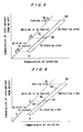
- FIGS. 5 and 6 are absorption refrigeration cycle diagrams of the absorption chiller-heater.
- the horizontal axis represents the temperature of solution
- the vertical axis represents the temperature of refrigerant (saturation temperature of refrigerant vapor).
- the cycles are illustrated on the Dlicking Diagram.
- FIG. 5 shows an absorption refrigeration cycle in the absorption chiller-heater shown in FIG. 1A
- FIG. 6 shows an absorption refrigeration cycle in the absorption chiller-heater shown in FIG. 2A.
- the solution is supplied from the absorber A to the side to be heated of the low-temperature heat exchanger XL, and then passes through the low-temperature heat exchanger XL and is branched at the branch point 10.
- a part of the solution branched at the branch point 10 is introduced into the low-temperature generator GL.
- the remaining solution branched at the branch point 10 passes through the side to be heated of the high-temperature heat exchanger XH, and is introduced into the high-temperature generator GH.
- the solution is heated by the high-temperature exhaust gas, and hence the solution is concentrated while refrigerant vapor 1 ⁇ is generated.
- the generated refrigerant vapor 1 ⁇ is introduced into the heating side of the low-temperature generator GL to heat the solution in the side to be heated of the low-temperature generator GL, and thus becomes condensed liquid and is led to the condenser C.
- the solution discharged from the high-temperature generator GH is supplied to the heating side of the high-temperature heat exchanger XH to supply heat to weak solution, and thus the temperature of the solution is lowered.
- the solution led to the low-temperature generator GL is heated by the refrigerant vapor 1 ⁇ supplied from the high-temperature generator GH, and is thus concentrated while refrigerant vapor 2 ⁇ is generated.
- the strong solution is then introduced into the exhaust heat recovery generator GR where the strong solution is heated by the exhaust gas which has passed through the high-temperature generator GH.
- the strong solution is concentrated while refrigerant vapor 2 ⁇ is generated in the exhaust heat recovery GR.
- the concentrated strong solution joins the strong solution discharged from the high-temperature heat exchanger XH, and the combined strong solution is introduced into the heating side of the low-temperature heat exchanger XL to supply heat to the weak solution.
- the combined strong solution lowers its temperature, and is returned to the absorber A.
- the strong solution absorbs refrigerant vapor 3 ⁇ supplied from the evaporator E to become weak solution.
- the temperature of the solution is increased by the exhaust heat recovery heat exchanger XB after the solution passes through the side to be heated of the low-temperature heat exchanger XL. Further, the temperature of the solution is increased by the exhaust heat recovery heat exchanger XA after the solution passes through the side to be heated of the high-temperature heat exchanger XH.
- Other operations of the embodiment shown in FIG. 6 are the same as those of the embodiment shown in FIG. 5.
- the flow of the solution is not limited to the embodiments shown in FIGS. 1A and 2A.
- the weak solution from the absorber may be introduced in parallel into the high-temperature generator and the exhaust heat recovery generator. Further, the solution introduced into the low-temperature generator may be weak solution as described above, or strong solution concentrated in the high-temperature generator.
- the structure shown in FIGS. 1A and 1B, and 2A and 2B can deal with various absorption refrigeration cycle flow.
- the high-temperature generator and the exhaust heat recovery generator which have the above structure and utilize a high-temperature exhaust gas as a heat source are disposed in series, the generators which can utilize a high-temperature exhaust gas effectively by a simple apparatus structure can be constructed.
- the absorption chiller-heater which is driven by the exhaust gas and has high heat exchanger effectiveness can be constructed.
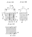
- FIGS. 7A, 7B and 7C, and FIGS. 8A and 8B a generator for use in an absorption chiller-heater according to an embodiment of a second aspect of the present invention will be described with reference to FIGS. 7A, 7B and 7C, and FIGS. 8A and 8B.
- a vertical heat transfer tube bank is provided between an upper tube plate and a lower tube plate, and a plurality of vertical downcomers are provided between the upper tube plate and the lower tube plate.
- heat insulating material is wound around the outer surface of the vertical heat transfer tube to change the function of the heat transfer tube to the function of the downcomer.
- a tube is inserted into the vertical heat transfer tube, and the interior of the inserted tube is used as a downcomer.
- a separator having a semicylindrical shape should be provided at the upper part of the inserted tube to separate ascending gas-liquid two-phase flow and descending solution from each other.
- FIGS. 7A, 7B and 7C are enlarged views showing a generator for use in the absorption chiller-heater according to an embodiment of the present invention
- FIG. 7A is a cross-sectional view taken along a flow direction of an exhaust gas
- FIG. 7B is a cross-sectional view taken along a direction perpendicular to the flow direction of the exhaust gas
- FIG. 7C is a view as viewed from line VII-VII of FIG. 7A.
- reference numeral 31 represents a generator
- reference numeral 32 represents vertical heat transfer tubes
- reference numeral 33 represents a downcomer
- reference numeral 34 represents an upper tube plate
- reference numeral 35 represents a lower tube plate.
- reference numeral 36 represents a solution supply chamber
- reference numeral 37 represents a gas-liquid separation chamber
- reference numeral 38 represents absorption solution (weak solution)
- reference numeral 39 represents absorption solution (strong solution).
- reference numeral 40 represents refrigerant vapor
- reference numeral 41 represents an exhaust gas (gaseous fluid)
- reference numeral 42 represents heat insulating material.
- a vertical heat transfer tube bank comprising the vertical heat transfer tubes 32, and the donwcomers 33 are provided between the upper tube plate 34 and the lower tube plate 35, the gas-liquid separation chamber 37 is provided above the vertical heat transfer tube bank so as to cover opening portions of the vertical heat transfer tube bank, and the solution supply chamber 36 is provided below the vertical heat transfer tube bank so as to cover opening portions of the vertical heat transfer tube bank.
- the sides of the generator comprise flat plates for defining an exhaust gas path which allows the exhaust gas 41 to pass therethrough.
- the absorption solution 38 passes through the vertical heat transfer tubes 32, and the gaseous fluid (exhaust gas) 41 serving as a heat source flows outside the vertical heat transfer tubes 32.
- the generator is simpler in structure than the conventional generator whose sides comprise a liquid-cooled wall (double wall having solution therebetween).
- a liquid-cooled wall is desirable.
- the exhaust gas has a temperature of about 300 to 400°C or lower, a simple flat plate may be employed.
- the absorption solution 38 in the vertical heat transfer tubes 32 is heated by the exhaust gas 41 outside the tubes and is boiled to form gas-liquid two-phase flow, and is then blown into the gas-liquid separation chamber 37.
- the gas-liquid mixture is separated into the refrigerant vapor 40 and the absorption solution.
- the absorption solution 38 is supplied from the solution supply chamber 36 to the lower portions of the vertical heat transfer tubes 32.
- a part of the absorption solution in the gas-liquid separation chamber 37 passes through the dowmcomers 33, and is returned to the solution supply chamber 36 and circulated as the absorption solution 38.
- the downcomer 33 is provided in the vertical heat transfer tube 32, and hence the downcomer 33 is heated by the gaseous fluid (exhaust gas) 41 serving as a heat source.
- the solution in the downcomer 33 is prevented from being heated as much as possible by the heat insulating material 42 outside the downcomer, thus becoming in a liquid phase condition or a condition containing a small amount of vapor.
- the absorption solution 38 in the downcomer 33 has larger apparent density than the solution of two-phase condition in the vertical heat transfer tube 32, and hence forms a descending flow.
- the downcomer 33 because apparent density of the solution in the downcomer 33 is larger than that of the solution in the vertical heat transfer tube 32, a descending flow of the solution is formed in the downcomer and an ascending flow of the solution is formed in the vertical heat transfer tube.
- the present invention is applicable to the conventional generator whose sides comprise a liquid-cooled wall (double wall with solution therebetween).
- the downcomer may be provided in the vertical heat transfer tube bank.
- FIGS. 8A and 8B are enlarged views showing a generator for use in the absorption chiller-heater according to another embodiment of the present invention, and FIG. 8A is a front sectional view and FIG. 8B is a view as viewed from line VIII-VIII of FIG. 8A.
- reference numeral 43 represents a clearance of a double tube
- reference numeral 44 represents an inner tube
- reference numeral 45 represents a separator
- reference numeral 46 represents a baffle plate.
- Other structure in the embodiment shown in FIGS. 8A and 8B is the same as that in the embodiment shown in FIGS. 7A, 7B and 7C.
- the downcomer 33 comprising the inner tube 44 of the double tube is provided in the vertical heat transfer tube 32.
- the absorption solution 38 in the clearance 43 of the double tube is heated by the gaseous fluid (exhaust gas) 41 serving as a heat source and flowing outside the double tube to generate vapor.
- the absorption solution 38 in the inner tube 44 is heated by the absorption solution 38 in the clearance 43 of the double tube, and hence a heating degree of the absorption solution in the inner tube 44 is lower than that of the absorption solution heated directly by the gaseous fluid 41 serving as a heating source. Therefore, in this case also, the same effect as the case shown in FIGS. 7A through 7C where heat insulation is performed can be obtained and a descending flow of the absorption solution is formed in the downcomer 33 comprising the inner tube 44.
- the outer tube of the double tube is constructed to have no fins so that the difference of the quantity of heat to be transferred is large, and hence the difference of apparent density can be enlarged.
- a releasing location of vapor is provided, and this releasing location and the inflow location of liquid at the upper portion of the double tube are separated from each other.
- a half-cut section of the inner tube serves as the separator 45, and the baffle plate 46 located at the clearance serves as a connecting passage for leading liquid to the inner tube.
- the present invention having the above structure is applicable to the generator having no liquid-cooled wall. Further, in the present invention, a downcomer is not provided outside the outer wall of the generator to make the structure of the generator simple. Therefore, the generator for use in the absorption chiller-heater which can reduce the amount of absorption solution to be reserved and has high efficiency can be constructed.
- a gas-liquid separation chamber is provided above the vertical heat transfer tube bank so as to cover opening portions of the vertical heat transfer tube bank, at least one baffle plate is provided in the gas-liquid separation chamber to divide the vertical heat transfer tube bank into a plurality of blocks in a flow direction of the gaseous fluid, a solution supply chamber is provided below the vertical heat transfer tube bank so as to cover opening portions of the vertical heat transfer tube bank, and at least one baffle plate is provided in the solution supply chamber so as to divide the vertical heat transfer tube bank into a plurality of blocks in a flow direction of the gaseous fluid.
- a solution inlet is provided at the upper block or the lower block located at the outlet side of the gaseous fluid
- a solution outlet is provided at the upper block located at the inlet side of the gaseous fluid.
- the positional relationship of the inlet and outlet of the solution is arranged such that the solution flows as a whole in a countercurrent flow to the gaseous fluid, the flow of the solution is regulated by the baffle plate, and the solution is not mixed as a whole in the flow direction.
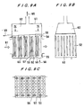
- FIGS. 9A, 9B and 9C are enlarged views showing a generator for use in an absorption chiller-heater according to an embodiment of the present invention
- FIG. 9A is a cross-sectional view taken along a flow direction of an exhaust gas
- FIG. 9B is a cross-sectional view taken along a direction perpendicular to the flow direction of the exhaust gas
- FIG. 9C is a view as viewed from line IX-IX of FIG. 9A.
- FIGS. 10 through 12 are schematic views of a generator for use in an absorption chiller-heater according to other embodiments of the present invention.
- reference numeral 51 represents a generator
- reference numeral 52 represents vertical heat transfer tubes
- reference numeral 53 represents a downcomer
- reference numeral 54 represents an upper tube plate
- reference numeral 55 represents a lower tube plate
- reference numeral 56 represents an upper baffle plate
- reference numeral 57 represents a lower baffle plate
- reference numeral 58 represents absorption solution (weak solution)
- reference numeral 59 represents absorption solution (strong solution).
- reference numeral 60 represents refrigerant vapor
- reference numeral 61 represents an exhaust gas (gaseous fluid) serving as a heat source
- reference numeral 62 represents a gas-liquid separation chamber
- reference numeral 63 represents a solution supply chamber.
- a vertical heat transfer tube bank comprising the vertical heat transfer tubes 52 is provided between the upper tube plate 54 and the lower tube plate 55, the gas-liquid separation chamber 62 is provided above the vertical heat transfer tube bank so as to cover opening portions of the vertical heat transfer tube bank, and the solution supply chamber 63 is provided below the vertical heat transfer tube bank so as to cover opening portions of the vertical heat transfer tube bank.
- the baffle plates 56 and 57 are provided so as to divide the vertical heat transfer tube bank into a plurality of blocks in a flow direction of the exhaust gas. That is, a plurality of the baffle plates 57 are provided to divide the solution supply chamber 63 into a plurality of small chambers in a flow direction of the exhaust gas.
- Each of the baffle plates 57 extends from the lower tube plate 55 to the bottom wall of the solution supply chamber 63 to divide the solution supply chamber 63 into a plurality of small chambers.
- the solution supply chamber 63 is divided into five small chambers.
- a plurality of the baffle plates 56 are provided in the gas-liquid separation chamber 62.
- Each of the baffle plates 56 extends from the upper tube plate 54, and has a certain height so that the gas-liquid separation chamber 62 is not divided above the upper end of the baffle plate 56 but is divided below the upper end of the baffle plate 56.
- five spaces for storing the solution therein are formed above the upper tube plate 54 in the gas-liquid separation chamber 62.
- the upper baffle plate 56 and the lower baffle plate 57 form a pair or a counterpart.
- the vertical heat transfer tube bank is functionally divided into five blocks by the upper baffle plates 56 and the lower baffle plates 57 so that the solution can flow separately in the respective blocks each comprising the vertical heat transfer tubes 52.
- the absorption solution 58 passes through the vertical heat transfer tubes 52, and the gaseous fluid 61 serving as a heat source flows outside the vertical heat transfer tubes 52.
- the absorption solution 58 in the vertical heat transfer tubes 52 is heated by the exhaust gas 61 outside the tubes and is boiled to form gas-liquid two-phase flow, and is then blown into the gas-liquid separation chamber 62.
- the gas-liquid mixture is separated into the refrigerant vapor 60 and the absorption solution.
- the absorption solution 58 is supplied from the solution supply chamber 63 to the lower portions of the vertical heat transfer tubes 52.
- a part of the absorption solution in the gas-liquid separation chamber 62 passes through the dowmcomers 53, and is returned to the solution supply chamber 63 and circulated as the absorption solution.
- the remaining solution overflows the baffle plate 56 in the gas-liquid separation chamber 62 and flows into the subsequent block.
- the solution is supplied from the gas-liquid separation chamber 62 to the solution supply chamber 63 through the downcomers 53.
- an ascending flow of the solution is generated in the vertical heat transfer tubes 52, the solution is circulated between the upper chamber and the lower chamber, and a part of the solution overflows into the following block.
- the absorption solution supplied to the first small chamber (first block) in the solution supply chamber 63 located at the right side end in FIG. 9A flows into the first block of the vertical heat transfer tube bank located at the right side end in FIG. 9A.
- a part of solution in the first space (first block) in the gas-liquid separation chamber 62 located at the right side end in FIG. 9A passes through the downcomers 53, and is returned to the first small chamber in the solution supply chamber 63 and circulated as the absorption solution.
- the remaining solution overflows the baffle plate 56 located at the right side end in FIG. 9A and flows into the second space (second block).
- the solution is supplied from the second space of the gas-liquid separation chamber 62 to the second small chamber (second block) in the solution supply chamber 63 through the downcomers 53.
- an ascending flow of the solution is generated in the heat transfer tubes 52 at the second block, the solution is circulated between the second space (second block) and the second small chamber (second block), and a part of the solution overflows into the third space (third block). The same flow of the solution is created in the subsequent blocks.
- the vertical heat transfer tube bank is divided into five blocks. Even if the vertical heat transfer tube bank is divided into more than five blocks, the same flow of the solution is created.
- the solution which has overflowed the baffle plate 56 in the preceding space (preceding block) in the gas-liquid separation chamber 62 enters the final space (final block), and the solution is supplied from the final space in the gas-liquid separation chamber 62 to the final small chamber (final block) in the solution supply chamber 63 through the downcomers 53.
- an ascending flow of the solution is generated in the vertical heat transfer tubes 52, the solution is circulated between the upper chamber and the lower chamber, and a part of the solution becomes strong solution and is discharged from the outlet of the generator 51.
- the concentration of the absorption solution 58 is gradually increased from the inlet block to the outlet block, and while the boiling temperature of the absorption solution 58 is gradually increased, the absorption solution 58 flows toward the outlet block.
- the absorption solution 58 and the gaseous fluid serving as a heat source flow in a countercurrent flow.
- the exhaust gas is utilized as a heat source.
- the present invention is applicable to the case where the flat-flamed burner is provided. Further, the present invention is applicable to a vertical heat transfer tube section in the generator which incorporates a cylindrical-flamed burner.
- the downcomers are provided in the vertical heat transfer tube bank.
- the downcomers may be provided outside the shell.
- the absorption chiller-heater according to the present invention can be applied to a single-effect absorption chiller-heater or a double-effect absorption chiller-heater or a single-effect and double-effect absorption chiller-heater which incorporates a generator connected thereto.
- the baffle plates in the solution supply chamber may be provided so as to partition the adjacent blocks. However, a hole may be formed in the baffle plate so as to allow the solution to flow between the adjacent two blocks.
- the baffle plate in the gas-liquid separation chamber employs an overflowing arrangement in the embodiment.
- a notch may be formed in the lower part of the baffle plate to allow a part of the solution to pass therethrough.
- FIG. 10 is a schematic view of a generator for use in an absorption chiller-heater according to another embodiment of the present invention.
- the solution overflows the baffle plate 56 in the gas-liquid separation chamber 62 and flows into the subsequent block.
- the solution may be supplied to the subsequent block by the downcomer 53. That is, the solution in the first block of the gas-liquid separation chamber 62 may be supplied to the second block of the solution supply chamber 63.
- FIG. 11 is a schematic view of a generator for use in an absorption chiller-heater according to another embodiment of the present invention.
- the absorption solution 58 (weak solution) is supplied to the small chamber in the solution supply chamber 63 in the generator, and the absorption solution 58 in the vertical heat transfer tubes is heated by the exhaust gas 61 outside the tubes and is boiled to form gas-liquid two-phase flow, and is then blown into the gas-liquid separation chamber 62.
- the gas-liquid mixture is separated into the refrigerant vapor 60 and the absorption solution.
- the absorption solution in the space (block) in the gas-liquid separation chamber 62 is supplied to the subsequent small chamber (subsequent block) in the solution supply chamber 63 through the downcomer 53. Further, the whole solution may be supplied to the subsequent block through the downcomer 53, or may be supplied to the subsequent block by overflowing the baffle plate 56 in the gas-liquid separation chamber 62. The same holds true for the following blocks.
- a part of the solution of the second block in the solution supply chamber 63 flows upwardly to the first block in the gas-liquid separation chamber 62 through the vertical heat transfer tubes 52, and the remaining solution flows upwardly to the second block in the gas-liquid separation chamber 62 through the vertical heat transfer tubes 52.
- the solution flows as a whole from the first block to the second block. However, a part of the solution is returned from the second block to the first block, and circulated up and down.
- the absorption solution of the second block in the gas-liquid separation chamber 62 is supplied to the third block of the solution supply chamber 63 through the downcomer 53.
- a part of the solution of the third block in the solution supply chamber 63 flows upwardly to the second block in the gas-liquid separation chamber 62 through the vertical heat transfer tubes 52, and the remaining solution flows upwardly to the third block in the gas-liquid separation chamber 62 through the vertical heat transfer tubes 52.
- a part of the solution of the third block in the gas-liquid separation chamber 62 is returned to the solution supply chamber 63 through the downcomer 53, and the remaining solution is discharged from the generator 51.
- FIG. 12 is a schematic view of a generator for use in an absorption chiller-heater according to still another embodiment of the present invention.
- the absorption solution 58 (weak solution) is supplied to the solution supply chamber 63 in the generator, the absorption solution 58 in the vertical heat transfer tubes 52 is heated by the exhaust gas 61 outside the tubes and is boiled to form gas-liquid two-phase flow, most part of the solution is blown into the block in the gas-liquid separation chamber 62 in the same order and the remaining solution is blown into the subsequent block in the gas-liquid separation chamber 62.
- the gas-liquid mixture is separated into the refrigerant vapor 60 and the absorption solution.
- the absorption solution of the gas-liquid separation chamber 62 is supplied to the block in the solution supply chamber 63 in the same order through the downcomer 53, a part of the solution moves to the subsequent block in the gas-liquid separation chamber 62 while it is circulated.
- the solution is supplied together with vapor from the second block of the solution supply chamber 63 to the third block of the gas-liquid separation chamber 62 through the vertical heat transfer tubes 52, a part of the solution is returned to the third block of the solution supply chamber 63 through the downcomer 53 and is circulated, and the remaining solution is discharged from the generator.
- the gaseous fluid serving as a heat source and the absorption solution flow as a whole in a countercurrent flow, and the gaseous fluid and the absorption solution are rarely mixed in a flow direction, thus making it possible to utilize the heat source gas effectively.
- FIGS. 13A, 13B and 13C, and FIGS. 14A and 14B a generator for use in an absorption chiller-heater according to an embodiment of the present invention will be described with reference to FIGS. 13A, 13B and 13C, and FIGS. 14A and 14B.
- the present invention is applied to an absorption chiller-heater which is driven by an exhaust gas having a temperature of 300 to 400°C or lower.
- the amount of solution to be reserved can be extremely small.
- the tube plates for the vertical transfer tubes are provided at the upper and lower portions of the generator, and the flat plates for defining an exhaust gas path are provided at the sides of the generator.
- the upper chamber and the lower chamber may be connected by downcomers. Further, since a temperature of the exhaust gas is low, a baffle plate for regulating the flow of the solution may be provided in the upper and lower chambers so that the exhaust gas and the solution flow as a whole in a countercurrent flow.
- FIGS. 13A, 13B and 13C are enlarged views showing a generator for use in an absorption chiller-heater according to an embodiment of the present invention
- FIG. 13A is a cross-sectional view taken along a flow direction of an exhaust gas
- FIG. 13B is a cross-sectional view taken along a direction perpendicular to the flow direction of the exhaust gas
- FIG. 13C is a view as viewed from line XIII-XIII of FIG. 13A.
- FIGS. 14A and 14B are enlarged views showing a generator for use in the absorption chiller-heater according to the embodiment of the fourth aspect of the present invention
- FIG. 14A is a cross-sectional view taken along a flow direction of an exhaust gas
- FIG. 14B is a cross-sectional view taken along a direction perpendicular to the flow direction of the exhaust gas.
- reference numeral 71 represents a generator
- reference numeral 72 represents an upper tube plate
- reference numeral 73 represents a lower tube plate
- reference numeral 74 represents vertical heat transfer tubes
- reference numeral 75 represents an upper chamber (gas-liquid separation chamber)
- reference numeral 76 represents a lower chamber (solution supply chamber).
- reference numeral 77 represents a flat plate which connects the upper and lower chambers
- reference numeral 78 represents absorption solution (weak solution)
- reference numeral 79 represents absorption solution (strong solution)
- reference numeral 80 represents refrigerant vapor
- reference numeral 81 represents an exhaust gas (heat source).
- reference numeral 82 represents a downcomer
- reference numeral 83 represents heat insulating material
- reference numeral 84 represents a baffle plate of the upper chamber
- reference numeral 85 represents a baffle plate of the lower chamber.
- a vertical heat transfer tube bank comprising the vertical heat transfer tubes 74 is provided between the upper tube plate 72 and the lower tube plate 73, the upper chamber (gas-liquid separation chamber) 75 is provided above the vertical heat transfer tube bank so as to cover opening portions of the vertical heat transfer tube bank, and the lower chamber (solution supply chamber) 76 is provided below the vertical heat transfer tube bank so as to cover opening portions of the vertical heat transfer tube bank. Further, the upper chamber 75 and the lower chamber 76 are connected by the flat plates 77, an exhaust gas path is formed so as to enclose the vertical heat transfer tube bank by the upper and lower tube plates 72 and 73, and the flat plates 77.
- the absorption solution 78 passes through the vertical heat transfer tubes 74, and the gaseous fluid (exhaust gas) 81 serving as a heat source flows outside the vertical heat transfer tubes 74. Further, the downcomers 82 are provided in a part of the vertical heat transfer tube bank.
- the absorption solution 78 in the vertical heat transfer tubes 74 is heated by the exhaust gas 81 outside the tubes and is boiled to form gas-liquid two-phase flow, and is then blown into the upper chamber (gas-liquid separation chamber) 75.
- the gas-liquid mixture is separated into the refrigerant vapor 80 and the absorption solution.
- the absorption solution is supplied from the solution supply chamber 76 to the lower portions of the vertical heat transfer tubes 74.
- a part of the absorption solution in the gas-liquid separation chamber 75 passes through the downcomers 82, and is returned to the solution supply chamber 76 and circulated as the absorption solution.
- the downcomer 82 is provided in the vertical heat transfer tube 74, and hence the downcomer 82 is heated by the gaseous fluid 81 serving as a heat source. However, the solution in the downcomer 82 is prevented from being heated as much as possible by the heat insulating material 83 outside the downcomer 82, thus becoming in a liquid phase condition or a condition containing a small amount of vapor.
- the absorption solution 78 in the downcomer 82 has larger apparent density than the solution of two-phase condition in the vertical heat transfer tube 74, and hence forms a descending flow.
- the vertical heat transfer tubes are shown in tessellated arrangement or in staggered arrangement.
- the vertical heat transfer tube is shown as a smooth tube. However, a part of the vertical heat transfer tubes or the whole of the vertical heat transfer tubes may comprise finned tubes.
- the downcomers 82 are provided in the vertical heat transfer tube bank. However, as shown in FIGS. 14A and 14B, the downcomers 82 may be provided outside the shell.
- baffle plates 84 and 85 are provided in the upper chamber 75 and the lower chamber 76, respectively. If the absorption solution 78 and the exhaust gas 81 flow as a whole in a countercurrent flow as shown by arrows, then heat transfer can be effectively performed. Further, the mean temperature difference between the gas and the solution can be large, and the quantity of heat to be transferred can be increased.
- the amount of solution to be reserved can be extremely smaller than the conventional generator whose sides comprise a liquid-cooled wall (double wall with solution therebetween), the structure of the generator can be simple, the generator can be easily manufactured, and inspection of airtightness can be easily performed.
- an exhaust gas generally has a low pressure of 10 to 200 mmAq, and the differential pressure applied to the side wall is about 0.1 to 2 % of the conventional vacuum container.
- the required strength of the plate for forming the side wall is extremely small.
- the generator according to the second through forth aspects of the present invention may be applied to a single-effect absorption chiller-heater or a double-effect absorption chiller-heater or a single-effect and double-effect absorption chiller-heater shown in FIG. 1A.
- FIG. 15 is a schematic circuit diagram of an absorption chiller-heater according to an embodiment of the present invention.
- an absorber A a low-temperature generator GL, a high-temperature generator GH, a condenser C, an evaporator E, a low-temperature heat exchanger XL, and a high-temperature heat exchanger XH.
- a solution pump SP and a refrigerant pump RP.
- reference numerals 1 and 2 represent refrigerant vapor passages
- reference numerals 3 and 4 represent cooling water circulation passages
- reference numeral 5 represents a high-temperature exhaust gas
- reference numeral 6 represents a cold or hot water circulation passage.
- reference numerals 7, 8 and 9 represent spray pipes
- the reference numeral 10 represents a branch point
- reference numerals 11 through 16 represent solution passages
- reference numerals 18 through 20 represent refrigerant passages.
- the solution which has absorbed refrigerant is supplied by the solution pump SP from the absorber A to the side to be heated of the low-temperature heat exchanger XL through the passage 11, and then passes through the low-temperature heat exchanger XL and is branched at the branch point 10.
- a part of the solution branched at the branch point 10 passes through the passage 16 and is introduced into the low temperature generator GL.
- the remaining solution passes through the side to be heated of the high-temperature heat exchanger XH, and is led to the high-temperature generator GH through the passage 11.
- the solution is heated by the exhaust gas 5 discharged from an external gas turbine or the like and serving as a heat source to generate refrigerant and is thus concentrated.
- the concentrated solution passes through the passage 12 and is introduced into the high-temperature heat exchanger XH.
- the solution joins the solution flowing through the passage 13, and the combined solution is introduced into the heating side of the low-temperature heat exchanger XL.
- the solution which has been introduced into the low-temperature generator GL through the passage 16 is sprayed from the spray nozzle 8 on the vertical heat transfer tube bank and heated by the refrigerant vapor generated in the high-temperature generator GH and is concentrated. Then, the concentrated solution joins the solution flowing through the passage 13.
- the combined solution passes through the heating side of the low-temperature heat exchanger XL and the passage 15, and is introduced into the absorber A.
- the refrigerant vapor generated in the low-temperature generator GL is introduced into the condenser C.
- the refrigerant vapor is condensed by heat exchange with cooling water flowing through the cooling water circulation passage 4.
- the refrigerant vapor which has generated in the high-temperature generator GH and served as a heat source of the low-temperature generator GL becomes condensed liquid and enters the condenser C, and is then introduced together with the above condensed refrigerant liquid condensed in the condenser C into the evaporator E.
- the refrigerant liquid deprives the cold water of heat to achieve a refrigerating effect, and becomes refrigerant vapor.
- the strong solution passes through the heating side of the low-temperature heat exchanger XL and is returned to the absorber A, and is then sprayed on the heat transfer surface which is being cooled by the cooling water. Then, the sprayed strong solution absorbs the refrigerant vapor supplied from the evaporator E and becomes weak solution.
Landscapes
- Engineering & Computer Science (AREA)
- Physics & Mathematics (AREA)
- Mechanical Engineering (AREA)
- Thermal Sciences (AREA)
- General Engineering & Computer Science (AREA)
- Power Engineering (AREA)
- Sorption Type Refrigeration Machines (AREA)
Applications Claiming Priority (8)
| Application Number | Priority Date | Filing Date | Title |
|---|---|---|---|
| JP2001242285A JP2003056939A (ja) | 2001-08-09 | 2001-08-09 | 排ガス駆動吸収冷温水機 |
| JP2001242285 | 2001-08-09 | ||
| JP2002022088A JP2003222434A (ja) | 2002-01-30 | 2002-01-30 | 排ガス駆動吸収冷温水機用再生器 |
| JP2002022087 | 2002-01-30 | ||
| JP2002022087A JP2003222433A (ja) | 2002-01-30 | 2002-01-30 | 吸収冷温水機用再生器 |
| JP2002022088 | 2002-01-30 | ||
| JP2002022086A JP4148496B2 (ja) | 2002-01-30 | 2002-01-30 | 吸収冷温水機用再生器 |
| JP2002022086 | 2002-01-30 |
Publications (3)
| Publication Number | Publication Date |
|---|---|
| EP1286121A2 true EP1286121A2 (de) | 2003-02-26 |
| EP1286121A3 EP1286121A3 (de) | 2004-09-08 |
| EP1286121B1 EP1286121B1 (de) | 2012-10-10 |
Family
ID=27482494
Family Applications (1)
| Application Number | Title | Priority Date | Filing Date |
|---|---|---|---|
| EP02017940A Expired - Lifetime EP1286121B1 (de) | 2001-08-09 | 2002-08-09 | Austreiber für ein Absorptionskühl- und Heizgerät |
Country Status (4)
| Country | Link |
|---|---|
| US (1) | US6694772B2 (de) |
| EP (1) | EP1286121B1 (de) |
| KR (1) | KR100907513B1 (de) |
| CN (1) | CN1262803C (de) |
Cited By (5)
| Publication number | Priority date | Publication date | Assignee | Title |
|---|---|---|---|---|
| WO2005059466A1 (en) * | 2003-12-11 | 2005-06-30 | Utc Power, Llc. | High-efficiency turbulators for high-stage generator of absorption chiller/heater |
| CN1321311C (zh) * | 2005-06-23 | 2007-06-13 | 上海交通大学 | 基于燃气内燃机的冷热电三联供系统的热管理器 |
| CN102287958A (zh) * | 2011-06-20 | 2011-12-21 | 沈阳化工大学 | 一种溴化锂溶液吸收式空调的制冷工艺 |
| CN103512265A (zh) * | 2013-09-28 | 2014-01-15 | 昆山市周市溴化锂溶液厂 | 溴化锂溶液吸收式制冷装置 |
| EP2803923B1 (de) * | 2013-05-15 | 2017-11-29 | Ago Ag Energie + Anlagen | Absorptionsprozess und -maschine |
Families Citing this family (20)
| Publication number | Priority date | Publication date | Assignee | Title |
|---|---|---|---|---|
| WO2003091163A2 (en) * | 2002-04-24 | 2003-11-06 | Liprie Randal C | Cogeneration wasteheat evaporation system and method for wastewater treatment utilizing wasteheat recovery |
| JP2004239558A (ja) * | 2003-02-07 | 2004-08-26 | Yazaki Corp | 吸収式冷温水機 |
| US7284709B2 (en) * | 2003-11-07 | 2007-10-23 | Climate Energy, Llc | System and method for hydronic space heating with electrical power generation |
| JP2006009713A (ja) * | 2004-06-28 | 2006-01-12 | Hitachi Ltd | コージェネレーションシステム及びエネルギー供給システム |
| KR100579576B1 (ko) * | 2004-08-17 | 2006-05-15 | 엘지전자 주식회사 | 열병합 발전 시스템 |
| KR100600752B1 (ko) * | 2004-08-17 | 2006-07-14 | 엘지전자 주식회사 | 열병합 발전 시스템 |
| KR100812712B1 (ko) * | 2006-11-09 | 2008-03-12 | 주식회사 신성엔지니어링 | 흡수식 냉동기용 고온재생기 |
| CN100453927C (zh) * | 2007-02-12 | 2009-01-21 | 庞启东 | 利用尾气余热的氨水吸收式制冷装置用的尾气换热器 |
| CN100447502C (zh) * | 2007-08-30 | 2008-12-31 | 南京工业大学 | 两级热管废热溴化锂制冷机发生器 |
| FR2921468B1 (fr) * | 2007-09-25 | 2009-12-18 | Peugeot Citroen Automobiles Sa | Procede de calcul et de regulation de la concentration de fluide absorbant dans un dispositif de climatisation par absorption, et dispositif de climatisation par absorption pour la mise en oeuvre d'un tel procede |
| US8286431B2 (en) * | 2009-10-15 | 2012-10-16 | Siemens Energy, Inc. | Combined cycle power plant including a refrigeration cycle |
| CN102242982B (zh) * | 2010-05-14 | 2015-04-29 | 荏原冷热系统株式会社 | 吸收热泵 |
| US9181876B2 (en) | 2012-01-04 | 2015-11-10 | General Electric Company | Method and apparatus for operating a gas turbine engine |
| US20140277754A1 (en) * | 2013-03-15 | 2014-09-18 | Tmg Energy Systems, Inc. | Integrated Sustainable Energy System |
| GB2547456B (en) * | 2016-02-18 | 2018-09-19 | Chilltechnologies Ltd | An absorption chiller |
| US10577973B2 (en) | 2016-02-18 | 2020-03-03 | General Electric Company | Service tube for a turbine engine |
| CN107477907A (zh) * | 2017-08-15 | 2017-12-15 | 双良节能系统股份有限公司 | 烟气热水复合型溴化锂吸收式冷水机组 |
| KR102800374B1 (ko) * | 2019-04-11 | 2025-04-25 | 엘지전자 주식회사 | 흡수식 냉동기 |
| CN115560959B (zh) * | 2021-06-30 | 2025-11-25 | 中国航发商用航空发动机有限责任公司 | 高温高压疲劳试验系统和方法 |
| US12092376B2 (en) * | 2022-07-19 | 2024-09-17 | King Fahd University Of Petroleum And Minerals | Absorption chiller refrigerator system |
Family Cites Families (17)
| Publication number | Priority date | Publication date | Assignee | Title |
|---|---|---|---|---|
| US3796045A (en) * | 1971-07-15 | 1974-03-12 | Turbo Dev Inc | Method and apparatus for increasing power output and/or thermal efficiency of a gas turbine power plant |
| US4009575A (en) * | 1975-05-12 | 1977-03-01 | said Thomas L. Hartman, Jr. | Multi-use absorption/regeneration power cycle |
| GB1515793A (en) * | 1976-08-02 | 1978-06-28 | Maloney Crawford Tank | Flameless reboiler for reconcentrating liquid desiccant |
| JPS57148673A (en) | 1981-03-11 | 1982-09-14 | Ricoh Co Ltd | Recording paper feeder |
| JPS58203371A (ja) * | 1982-05-21 | 1983-11-26 | 株式会社日立製作所 | 蒸気発生装置 |
| JP3283621B2 (ja) * | 1993-03-09 | 2002-05-20 | 川重冷熱工業株式会社 | 低温再生器と排熱回収用低温再生器とを併用した吸収冷凍機・冷温水機 |
| US5600967A (en) * | 1995-04-24 | 1997-02-11 | Meckler; Milton | Refrigerant enhancer-absorbent concentrator and turbo-charged absorption chiller |
| US5964103A (en) * | 1995-10-06 | 1999-10-12 | Hitachi, Ltd. | Absorption refrigerator and production method thereof |
| US5766519A (en) * | 1995-11-13 | 1998-06-16 | Erickson; Donald C. | Locally cocurrent globally crosscurrent pressure equalized absorber and process |
| US5862679A (en) * | 1996-04-30 | 1999-01-26 | Sanyo Electric Co., Ltd. | High-temperature regenerator |
| JP3837196B2 (ja) * | 1997-01-10 | 2006-10-25 | 三洋電機株式会社 | 高温再生器 |
| JP3927679B2 (ja) | 1998-02-27 | 2007-06-13 | 三洋電機株式会社 | 高温再生器 |
| JPH11304274A (ja) * | 1998-04-20 | 1999-11-05 | Kawasaki Thermal Eng Co Ltd | 廃熱利用吸収式冷温水機・冷凍機 |
| JP3824436B2 (ja) * | 1998-12-08 | 2006-09-20 | 荏原冷熱システム株式会社 | 三重効用吸収冷凍機 |
| GB9918581D0 (en) * | 1999-08-06 | 1999-10-06 | British Gas Plc | A generator for an absorption chiller |
| JP2002162131A (ja) * | 2000-11-27 | 2002-06-07 | Takuma Co Ltd | 吸収式廃熱回収設備 |
| KR100878514B1 (ko) * | 2001-07-09 | 2009-01-13 | 가부시키가이샤 에바라 세이사꾸쇼 | 흡수냉온수기 |
-
2002
- 2002-08-05 US US10/211,288 patent/US6694772B2/en not_active Expired - Fee Related
- 2002-08-08 KR KR1020020046718A patent/KR100907513B1/ko not_active Expired - Fee Related
- 2002-08-09 CN CNB021285284A patent/CN1262803C/zh not_active Expired - Fee Related
- 2002-08-09 EP EP02017940A patent/EP1286121B1/de not_active Expired - Lifetime
Non-Patent Citations (1)
| Title |
|---|
| None |
Cited By (7)
| Publication number | Priority date | Publication date | Assignee | Title |
|---|---|---|---|---|
| WO2005059466A1 (en) * | 2003-12-11 | 2005-06-30 | Utc Power, Llc. | High-efficiency turbulators for high-stage generator of absorption chiller/heater |
| US7117686B2 (en) | 2003-12-11 | 2006-10-10 | Utc Power, Llc | High-efficiency turbulators for high-stage generator of absorption chiller/heater |
| US7275393B2 (en) | 2003-12-11 | 2007-10-02 | Utc Power, Llc | High-efficiency turbulators for high-stage generator of absorption chiller/heater |
| CN1321311C (zh) * | 2005-06-23 | 2007-06-13 | 上海交通大学 | 基于燃气内燃机的冷热电三联供系统的热管理器 |
| CN102287958A (zh) * | 2011-06-20 | 2011-12-21 | 沈阳化工大学 | 一种溴化锂溶液吸收式空调的制冷工艺 |
| EP2803923B1 (de) * | 2013-05-15 | 2017-11-29 | Ago Ag Energie + Anlagen | Absorptionsprozess und -maschine |
| CN103512265A (zh) * | 2013-09-28 | 2014-01-15 | 昆山市周市溴化锂溶液厂 | 溴化锂溶液吸收式制冷装置 |
Also Published As
| Publication number | Publication date |
|---|---|
| EP1286121B1 (de) | 2012-10-10 |
| KR20030014640A (ko) | 2003-02-19 |
| CN1262803C (zh) | 2006-07-05 |
| EP1286121A3 (de) | 2004-09-08 |
| CN1405517A (zh) | 2003-03-26 |
| KR100907513B1 (ko) | 2009-07-14 |
| US20030029188A1 (en) | 2003-02-13 |
| US6694772B2 (en) | 2004-02-24 |
Similar Documents
| Publication | Publication Date | Title |
|---|---|---|
| US6694772B2 (en) | Absorption chiller-heater and generator for use in such absorption chiller-heater | |
| JP3445941B2 (ja) | 多段蒸発吸収型の吸収冷温水機及びそれを備えた大温度差空調システム | |
| KR100878514B1 (ko) | 흡수냉온수기 | |
| US5373709A (en) | Absorption type refrigerator | |
| KR890004393B1 (ko) | 공냉형 흡수식 냉수기 | |
| JP3997594B2 (ja) | 空冷吸収器 | |
| KR200155867Y1 (ko) | 수액기 일체형 응축기 | |
| JP3443786B2 (ja) | 吸収冷凍機 | |
| CN100513934C (zh) | 用在吸收式制冷加热装置中的发生器 | |
| US4468934A (en) | Absorption refrigeration system | |
| JP2004198087A (ja) | 吸収冷凍装置及び吸収冷凍システム | |
| JPS59158507A (ja) | 変圧器の熱交換装置 | |
| KR100286833B1 (ko) | 흡수식 냉난방 시스템의 재생기용 열교환기 | |
| KR100314471B1 (ko) | 암모니아를이용한흡수식열펌프의발생기 | |
| KR100360449B1 (ko) | 흡수식 냉난방기의 일체형 열교환기 | |
| JP2994253B2 (ja) | 吸収式空調装置 | |
| JP3413927B2 (ja) | 吸収式冷凍装置 | |
| JP3182166B2 (ja) | 吸収式冷凍機 | |
| KR100208181B1 (ko) | 흡수식 사이클의 냉매증기와 약용액 동향유로 시스템 | |
| JPH0354377Y2 (de) | ||
| JP3236722B2 (ja) | 吸収冷凍機用再生器 | |
| JPH07120098A (ja) | エンジン排熱回収吸収式冷温水機 | |
| JPH07208829A (ja) | 吸収式冷凍サイクルの発生器 | |
| JP2002310535A (ja) | 吸収冷凍機 | |
| JPH07318193A (ja) | 吸収式冷凍装置 |
Legal Events
| Date | Code | Title | Description |
|---|---|---|---|
| PUAI | Public reference made under article 153(3) epc to a published international application that has entered the european phase |
Free format text: ORIGINAL CODE: 0009012 |
|
| AK | Designated contracting states |
Kind code of ref document: A2 Designated state(s): AT BE BG CH CY CZ DE DK EE ES FI FR GB GR IE IT LI LU MC NL PT SE SK TR |
|
| AX | Request for extension of the european patent |
Extension state: AL LT LV MK RO SI |
|
| PUAL | Search report despatched |
Free format text: ORIGINAL CODE: 0009013 |
|
| AK | Designated contracting states |
Kind code of ref document: A3 Designated state(s): AT BE BG CH CY CZ DE DK EE ES FI FR GB GR IE IT LI LU MC NL PT SE SK TR |
|
| AX | Request for extension of the european patent |
Extension state: AL LT LV MK RO SI |
|
| RIC1 | Information provided on ipc code assigned before grant |
Ipc: 7F 25B 15/06 A Ipc: 7F 25B 33/00 B |
|
| 17P | Request for examination filed |
Effective date: 20041210 |
|
| AKX | Designation fees paid |
Designated state(s): DE DK ES GB IT NL |
|
| 17Q | First examination report despatched |
Effective date: 20060303 |
|
| REG | Reference to a national code |
Ref country code: DE Ref legal event code: R079 Ref document number: 60243828 Country of ref document: DE Free format text: PREVIOUS MAIN CLASS: F25B0015060000 Ipc: F25B0015000000 |
|
| RIC1 | Information provided on ipc code assigned before grant |
Ipc: F25B 15/00 20060101AFI20120209BHEP Ipc: F25B 33/00 20060101ALI20120209BHEP |
|
| RTI1 | Title (correction) |
Free format text: GENERATOR FOR USE IN AN ABSORPTION CHILLER-HEATER |
|
| GRAP | Despatch of communication of intention to grant a patent |
Free format text: ORIGINAL CODE: EPIDOSNIGR1 |
|
| GRAS | Grant fee paid |
Free format text: ORIGINAL CODE: EPIDOSNIGR3 |
|
| GRAA | (expected) grant |
Free format text: ORIGINAL CODE: 0009210 |
|
| AK | Designated contracting states |
Kind code of ref document: B1 Designated state(s): DE DK ES GB IT NL |
|
| REG | Reference to a national code |
Ref country code: GB Ref legal event code: FG4D |
|
| REG | Reference to a national code |
Ref country code: DE Ref legal event code: R096 Ref document number: 60243828 Country of ref document: DE Effective date: 20121206 |
|
| REG | Reference to a national code |
Ref country code: NL Ref legal event code: VDEP Effective date: 20121010 |
|
| PG25 | Lapsed in a contracting state [announced via postgrant information from national office to epo] |
Ref country code: NL Free format text: LAPSE BECAUSE OF FAILURE TO SUBMIT A TRANSLATION OF THE DESCRIPTION OR TO PAY THE FEE WITHIN THE PRESCRIBED TIME-LIMIT Effective date: 20121010 Ref country code: ES Free format text: LAPSE BECAUSE OF FAILURE TO SUBMIT A TRANSLATION OF THE DESCRIPTION OR TO PAY THE FEE WITHIN THE PRESCRIBED TIME-LIMIT Effective date: 20130121 |
|
| PG25 | Lapsed in a contracting state [announced via postgrant information from national office to epo] |
Ref country code: DK Free format text: LAPSE BECAUSE OF FAILURE TO SUBMIT A TRANSLATION OF THE DESCRIPTION OR TO PAY THE FEE WITHIN THE PRESCRIBED TIME-LIMIT Effective date: 20121010 |
|
| PLBE | No opposition filed within time limit |
Free format text: ORIGINAL CODE: 0009261 |
|
| STAA | Information on the status of an ep patent application or granted ep patent |
Free format text: STATUS: NO OPPOSITION FILED WITHIN TIME LIMIT |
|
| 26N | No opposition filed |
Effective date: 20130711 |
|
| REG | Reference to a national code |
Ref country code: DE Ref legal event code: R097 Ref document number: 60243828 Country of ref document: DE Effective date: 20130711 |
|
| PGFP | Annual fee paid to national office [announced via postgrant information from national office to epo] |
Ref country code: DE Payment date: 20170801 Year of fee payment: 16 Ref country code: IT Payment date: 20170824 Year of fee payment: 16 Ref country code: GB Payment date: 20170809 Year of fee payment: 16 |
|
| REG | Reference to a national code |
Ref country code: DE Ref legal event code: R119 Ref document number: 60243828 Country of ref document: DE |
|
| GBPC | Gb: european patent ceased through non-payment of renewal fee |
Effective date: 20180809 |
|
| PG25 | Lapsed in a contracting state [announced via postgrant information from national office to epo] |
Ref country code: DE Free format text: LAPSE BECAUSE OF NON-PAYMENT OF DUE FEES Effective date: 20190301 Ref country code: IT Free format text: LAPSE BECAUSE OF NON-PAYMENT OF DUE FEES Effective date: 20180809 |
|
| PG25 | Lapsed in a contracting state [announced via postgrant information from national office to epo] |
Ref country code: GB Free format text: LAPSE BECAUSE OF NON-PAYMENT OF DUE FEES Effective date: 20180809 |