EP1286024A2 - Anordnung einer Nockenwelle im Zylinderkopf einer Brennkraftmaschine - Google Patents
Anordnung einer Nockenwelle im Zylinderkopf einer Brennkraftmaschine Download PDFInfo
- Publication number
- EP1286024A2 EP1286024A2 EP02015997A EP02015997A EP1286024A2 EP 1286024 A2 EP1286024 A2 EP 1286024A2 EP 02015997 A EP02015997 A EP 02015997A EP 02015997 A EP02015997 A EP 02015997A EP 1286024 A2 EP1286024 A2 EP 1286024A2
- Authority
- EP
- European Patent Office
- Prior art keywords
- shaft collar
- housing
- bearing
- cylinder head
- camshaft
- Prior art date
- Legal status (The legal status is an assumption and is not a legal conclusion. Google has not performed a legal analysis and makes no representation as to the accuracy of the status listed.)
- Granted
Links
- 238000002485 combustion reaction Methods 0.000 title claims description 8
- RDYMFSUJUZBWLH-UHFFFAOYSA-N endosulfan Chemical compound C12COS(=O)OCC2C2(Cl)C(Cl)=C(Cl)C1(Cl)C2(Cl)Cl RDYMFSUJUZBWLH-UHFFFAOYSA-N 0.000 claims description 8
- 238000007789 sealing Methods 0.000 claims description 5
- 230000001050 lubricating effect Effects 0.000 claims description 3
- 238000005461 lubrication Methods 0.000 description 7
- 230000000694 effects Effects 0.000 description 1
- 230000008030 elimination Effects 0.000 description 1
- 238000003379 elimination reaction Methods 0.000 description 1
- 230000010354 integration Effects 0.000 description 1
Images
Classifications
-
- F—MECHANICAL ENGINEERING; LIGHTING; HEATING; WEAPONS; BLASTING
- F01—MACHINES OR ENGINES IN GENERAL; ENGINE PLANTS IN GENERAL; STEAM ENGINES
- F01L—CYCLICALLY OPERATING VALVES FOR MACHINES OR ENGINES
- F01L1/00—Valve-gear or valve arrangements, e.g. lift-valve gear
- F01L1/02—Valve drive
- F01L1/022—Chain drive
-
- F—MECHANICAL ENGINEERING; LIGHTING; HEATING; WEAPONS; BLASTING
- F01—MACHINES OR ENGINES IN GENERAL; ENGINE PLANTS IN GENERAL; STEAM ENGINES
- F01L—CYCLICALLY OPERATING VALVES FOR MACHINES OR ENGINES
- F01L1/00—Valve-gear or valve arrangements, e.g. lift-valve gear
- F01L1/02—Valve drive
- F01L1/04—Valve drive by means of cams, camshafts, cam discs, eccentrics or the like
- F01L1/047—Camshafts
- F01L1/053—Camshafts overhead type
-
- F—MECHANICAL ENGINEERING; LIGHTING; HEATING; WEAPONS; BLASTING
- F01—MACHINES OR ENGINES IN GENERAL; ENGINE PLANTS IN GENERAL; STEAM ENGINES
- F01L—CYCLICALLY OPERATING VALVES FOR MACHINES OR ENGINES
- F01L1/00—Valve-gear or valve arrangements, e.g. lift-valve gear
- F01L1/34—Valve-gear or valve arrangements, e.g. lift-valve gear characterised by the provision of means for changing the timing of the valves without changing the duration of opening and without affecting the magnitude of the valve lift
-
- F—MECHANICAL ENGINEERING; LIGHTING; HEATING; WEAPONS; BLASTING
- F01—MACHINES OR ENGINES IN GENERAL; ENGINE PLANTS IN GENERAL; STEAM ENGINES
- F01L—CYCLICALLY OPERATING VALVES FOR MACHINES OR ENGINES
- F01L1/00—Valve-gear or valve arrangements, e.g. lift-valve gear
- F01L1/34—Valve-gear or valve arrangements, e.g. lift-valve gear characterised by the provision of means for changing the timing of the valves without changing the duration of opening and without affecting the magnitude of the valve lift
- F01L1/344—Valve-gear or valve arrangements, e.g. lift-valve gear characterised by the provision of means for changing the timing of the valves without changing the duration of opening and without affecting the magnitude of the valve lift changing the angular relationship between crankshaft and camshaft, e.g. using helicoidal gear
- F01L1/34403—Valve-gear or valve arrangements, e.g. lift-valve gear characterised by the provision of means for changing the timing of the valves without changing the duration of opening and without affecting the magnitude of the valve lift changing the angular relationship between crankshaft and camshaft, e.g. using helicoidal gear using helically teethed sleeve or gear moving axially between crankshaft and camshaft
- F01L1/34406—Valve-gear or valve arrangements, e.g. lift-valve gear characterised by the provision of means for changing the timing of the valves without changing the duration of opening and without affecting the magnitude of the valve lift changing the angular relationship between crankshaft and camshaft, e.g. using helicoidal gear using helically teethed sleeve or gear moving axially between crankshaft and camshaft the helically teethed sleeve being located in the camshaft driving pulley
Definitions
- the invention relates according to the preamble of claim 1 to a Arrangement of a camshaft in the cylinder head of an internal combustion engine, in which the arranged in the cylinder head via a plain bearing combined with a thrust bearing Camshaft is equipped with a hydraulically controlled phaser, the a hydraulic medium from arranged in the cylinder head channels over a circumferential with a cylinder head side housing cooperating shaft collar and further channels in the camshaft is supplied, wherein the first channels with the second channels arranged in the shaft collar, covered by the housing and outwardly sealed circumferential grooves are in communication.
- Such an arrangement of a camshaft is known for example from FIGS and 4 of the German patent DE 195 25 836 C1.
- This known arrangement of a separate Wellenbundes next to a separate combined sliding / thrust bearing disadvantageously requires an additional length of the camshaft.
- the invention is based on the object, the generic arrangement of a To improve camshaft so that a camshaft with a shorter overall length achieved.
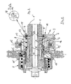
- camshafts 1, 1 ' which are each shown in half in FIGS. 1 and 2, differ from each other by phaser side differently shaped ends, what in relation to the inventive arrangement of a camshaft 1, 1 'in Cylinder head 2 of an internal combustion engine not shown in detail but without meaning is.
- a camshaft 1, 1 'in Cylinder head 2 of an internal combustion engine not shown in detail but without meaning is.
- the cylinder head 2 via a combined with a thrust bearing 3
- Slide bearing 4 arranged camshaft 1, 1 'with a hydraulically controlled Phasing plate 5 equipped.
- This phaser 5 is a hydraulic medium from arranged in the cylinder head 2 channels 6 and 7 over a circumferentially with a cylinder head side housing 8 cooperating shaft collar 9 and further channels 10 and 11 in the camshaft 1, 1 'supplied, wherein the first Channels 6, 7 with the second channels 10, 11 arranged in the shaft collar 9, Covered from the housing 8 and sealed to the outside circumferential grooves 12, 12 'in Connection stand.
- Camshaft is inventively proposed that divided in one trained housing 8 arranged shaft collar 9 an integrated arranged Slide bearing 4 with thrust bearing 3 comprises trained with both sides of the sliding bearing 4 axial thrust bearing abutment surfaces 13, 13 'in relation to the slide bearing diameter larger recesses 14, 14 'in the housing 8. In these recesses 14, 14 'engages the camshaft 1, 1' with diameter-adapted Weilbund sections 9 ', 9 "with circumferential or radial clearance such that in the shaft collar sections 9 ', 9 "arranged circumferential grooves 12, 12' only to the respective outer end side 15, 15 'of the housing 8 out in the recesses 14, 14' sealed are.
- a particularly effective and reliable sealing of the circumferential grooves 12, 12 'in the shaft collar sections 9', 9 "against the recesses 14, 14 'in the housing 8 is achieved by means arranged in annular grooves 17 hook rings 18, which in FIG 3 are shown in enlarged detail with cooperating at 19 Hook.
Landscapes
- Engineering & Computer Science (AREA)
- Mechanical Engineering (AREA)
- General Engineering & Computer Science (AREA)
- Valve-Gear Or Valve Arrangements (AREA)
- Valve Device For Special Equipments (AREA)
Abstract
Description
- Figur 1
- die Anordnung einer Nockenwelle mit kurzem stirnseitigem Ende,
- Figur 2
- die Anordnung einer Nockenwelle mit einem langen, stirnseitigen Überstand,
- Figur 3
- in einem vergrößerten Ausschnitt die ineinander greifenden Haken eines Hakenringes.
Claims (3)
- Anordnung einer Nockenwelle im Zylinderkopf einer Brennkraftmaschine,dadurch gekennzeichnet,bei der die im Zylinderkopf (2) über ein mit einem Spurlager (3) kombiniertes Gleitlager (4) angeordnete Nockenwelle (1, 1') mit einem hydraulisch gesteuerten Phasensteller (5) ausgerüstet ist, demein Hydraulikmedium aus im Zylinderkopf (2) angeordneten Kanälen (6, 7) über einen umfänglich mit einem zylinderkopfseitigen Gehäuse (8) zusammenwirkenden Wellenbund (9) und weiteren Kanälen (10, 11) in der Nockenwelle (1, 1') zugeführt ist, wobeidie ersten Kanäle (6, 7) mit den zweiten Kanälen (10, 11) über im Wellenbund (9) angeordnete, vom Gehäuse (8) abgedeckte und nach außen abgedichtete Umfangsnuten (12, 12') in Verbindung stehen,dass der in einem geteilt ausgebildeten Gehäuse (8) angeordnete Wellenbund (9) ein integriert angeordnetes Gleitlager (4) mit Spurlager (3) umfasst mit beiderseits des Gleitlagers (4) ausgebildeten axialen Spurlager-Anschlagflächen (13, 13') in gegenüber dem Gleitlager-Durchmesser größeren Ausnehmungen (14, 14') im Gehäuse (8), in diedie Nockenwelle (1, 1') mit im Durchmesser angepassten Wellenbund-Abschnitten (9', 9") mit Umfangs- bzw. Radialspiel derart eingreift, dassdie in den Wellenbund-Abschnitten (9', 9") angeordneten Umfangsnuten (12, 12') lediglich zur jeweiligen äußeren Stirnseite (15, 15') des Gehäuses (8) hin in den Ausnehmungen (14, 14') abgedichtet sind.
- Anordnung nach Anspruch 1, dadurch gekennzeichnet,dass ein im Gleitlager (4) austretender Schmierkanal (16) und die ersten und zweiten Hydraulikkanäle (6, 7; 10, 11) für den Phasensteller (5) mit dem Schmiersystem der Brennkraftmaschine in Verbindung stehen, unddass die Wellenbund-Abschnitte (9', 9") relativ zur Breite des Gleitlagers (4) zwischen den Spurlager-Anschlagflächen (13, 13') mit Axialspiel beabstandet angeordnet sind.
- Anordnung nach Anspruch 1 oder 2, dadurch gekennzeichnet, dass die Abdichtung der Umfangsnuten (12, 12') in den Wellenbund-Abschnitten (9', 9") gegen die Ausnehmungen (14, 14') im Gehäuse (8) mittels in Ringnuten (17) angeordneten Hakenringen (18) bewirkt ist.
Applications Claiming Priority (2)
| Application Number | Priority Date | Filing Date | Title |
|---|---|---|---|
| DE2001141213 DE10141213B4 (de) | 2001-08-23 | 2001-08-23 | Anordnung einer Nockenwelle im Zylinderkopf einer Brennkraftmaschine |
| DE10141213 | 2001-08-23 |
Publications (3)
| Publication Number | Publication Date |
|---|---|
| EP1286024A2 true EP1286024A2 (de) | 2003-02-26 |
| EP1286024A3 EP1286024A3 (de) | 2003-11-19 |
| EP1286024B1 EP1286024B1 (de) | 2008-02-27 |
Family
ID=7696286
Family Applications (1)
| Application Number | Title | Priority Date | Filing Date |
|---|---|---|---|
| EP20020015997 Expired - Lifetime EP1286024B1 (de) | 2001-08-23 | 2002-07-18 | Anordnung einer Nockenwelle im Zylinderkopf einer Brennkraftmaschine |
Country Status (2)
| Country | Link |
|---|---|
| EP (1) | EP1286024B1 (de) |
| DE (2) | DE10141213B4 (de) |
Cited By (2)
| Publication number | Priority date | Publication date | Assignee | Title |
|---|---|---|---|---|
| WO2008028902A1 (de) * | 2006-09-07 | 2008-03-13 | Mahle International Gmbh | Verstellbare nockenwelle |
| CN103080484A (zh) * | 2010-09-03 | 2013-05-01 | 株式会社捷太格特 | 凸轮轴装置 |
Families Citing this family (1)
| Publication number | Priority date | Publication date | Assignee | Title |
|---|---|---|---|---|
| CN108915814B (zh) * | 2018-08-28 | 2023-10-20 | 河南柴油机重工有限责任公司 | 一种共轨柴油机凸轮轴驱动装置 |
Citations (1)
| Publication number | Priority date | Publication date | Assignee | Title |
|---|---|---|---|---|
| DE19525836C1 (de) | 1995-07-15 | 1996-08-01 | Bayerische Motoren Werke Ag | Stellvorrichtung zur relativen Winkelverstellung einer angetriebenen Welle, insbesondere Nockenwelle einer Brennkraftmaschine |
Family Cites Families (6)
| Publication number | Priority date | Publication date | Assignee | Title |
|---|---|---|---|---|
| JP2924777B2 (ja) * | 1996-04-08 | 1999-07-26 | トヨタ自動車株式会社 | 内燃機関のバルブタイミング可変機構 |
| DE19616266A1 (de) * | 1996-04-24 | 1997-10-30 | Schaeffler Waelzlager Kg | Verdrehsicherung für Dichtringe einer Nockenwellenverstelleinrichtung |
| DE69611440T2 (de) * | 1996-07-11 | 2001-08-23 | Carraro S.P.A., Campodarsego | Eine Phasenverstellvorrichtung |
| DE19724989A1 (de) * | 1997-06-13 | 1998-12-17 | Schaeffler Waelzlager Ohg | Vorrichtung zum Verändern der Steuerzeiten in einer Brennkraftmaschine |
| DE19747244A1 (de) * | 1997-10-27 | 1999-04-29 | Schaeffler Waelzlager Kg | Zylinderkopf |
| DE19951391A1 (de) * | 1999-10-26 | 2001-07-05 | Schaeffler Waelzlager Ohg | Vorrichtung zum Verändern der Steuerzeiten von Gaswechselventilen einer Brennkraftmaschine, insbesondere hydraulische Nockenwellen-Verstelleinrichtung in Rotationsrichtung |
-
2001
- 2001-08-23 DE DE2001141213 patent/DE10141213B4/de not_active Expired - Fee Related
-
2002
- 2002-07-18 EP EP20020015997 patent/EP1286024B1/de not_active Expired - Lifetime
- 2002-07-18 DE DE50211771T patent/DE50211771D1/de not_active Expired - Lifetime
Patent Citations (1)
| Publication number | Priority date | Publication date | Assignee | Title |
|---|---|---|---|---|
| DE19525836C1 (de) | 1995-07-15 | 1996-08-01 | Bayerische Motoren Werke Ag | Stellvorrichtung zur relativen Winkelverstellung einer angetriebenen Welle, insbesondere Nockenwelle einer Brennkraftmaschine |
Cited By (5)
| Publication number | Priority date | Publication date | Assignee | Title |
|---|---|---|---|---|
| WO2008028902A1 (de) * | 2006-09-07 | 2008-03-13 | Mahle International Gmbh | Verstellbare nockenwelle |
| CN103080484A (zh) * | 2010-09-03 | 2013-05-01 | 株式会社捷太格特 | 凸轮轴装置 |
| EP2613029A4 (de) * | 2010-09-03 | 2015-01-07 | Jtekt Corp | Nockenwellenvorrichtung |
| US8991359B2 (en) | 2010-09-03 | 2015-03-31 | Jtekt Corporation | Camshaft device |
| CN103080484B (zh) * | 2010-09-03 | 2015-12-02 | 株式会社捷太格特 | 凸轮轴装置 |
Also Published As
| Publication number | Publication date |
|---|---|
| DE50211771D1 (de) | 2008-04-10 |
| DE10141213A1 (de) | 2003-03-06 |
| EP1286024B1 (de) | 2008-02-27 |
| EP1286024A3 (de) | 2003-11-19 |
| DE10141213B4 (de) | 2008-11-20 |
Similar Documents
| Publication | Publication Date | Title |
|---|---|---|
| DE69511627T2 (de) | Zwei-Stufen-Ventilstössel | |
| DE69800204T2 (de) | Verbesserte Nockenwelle einer Brennkraftmaschine | |
| DE19908286B4 (de) | Variable Ventilsteuerung für Brennkraftmaschinen | |
| DE2620910A1 (de) | Kolben | |
| DE19757504B4 (de) | Gebaute Nockenwelle für eine Brennkraftmaschine | |
| DE4236655A1 (de) | Ventilantrieb für eine Brennkraftmaschine | |
| DE69405555T2 (de) | Ventilsteueranordnung | |
| DE102016208470A1 (de) | Anordnung zur Lagerung von wenigstens einem Ventiltriebelement | |
| EP2627877B1 (de) | Aktuator eines elektrohydraulischen gaswechselventiltriebs einer brennkraftmaschine | |
| DE102011014277B4 (de) | Motorbaugruppe | |
| EP2653672B1 (de) | Brennkraftmaschine | |
| EP1286024B1 (de) | Anordnung einer Nockenwelle im Zylinderkopf einer Brennkraftmaschine | |
| EP1358397B1 (de) | Kipphebel für einen ventiltrieb eines verbrennungsmotors mit vorrichtung zur selbsttätigen ein-/nachstellung des ventilspiels | |
| DE102017112574B3 (de) | Hydraulisches Abstützelement mit einem Ringfilter | |
| DE102016208392A1 (de) | Nockenwelle | |
| DE102016200424A1 (de) | Variabler Ventiltrieb | |
| WO2017012614A1 (de) | Hydraulikelement mit motorbremsfunktion für eine viertakthubkolbenbrennkraftmaschine und viertakthubkolbenbrennkraftmaschine | |
| DE102017104629A1 (de) | Variabler Ventiltrieb eines Verbrennungskolbenmotors | |
| DE102012206178A1 (de) | Kipphebel | |
| DE102017104631A1 (de) | Vorrichtung und Verfahren zur Ventilhubsteuerung und Brennkraftmaschine | |
| DE19645964A1 (de) | Schaltbarer Tassenstößel für Gaswechselventile von Brennkraftmaschinen, insbesondere mit Zylinderabschaltung | |
| DE102017106987A1 (de) | Rückschlagventil für ein Pleuel für eine Brennkraftmaschine mit variabler Verdichtung | |
| DE102007037332A1 (de) | Schaltbare Abstützvorrichtung für einen Ventiltrieb einer Brennkraftmaschine | |
| DE102013209862A1 (de) | Anordnung eines Elektromagneten zur Ansteuerung eines Zentralventils | |
| DE102012106216A1 (de) | Schiebenockensystem mit einer Arretiervorrichtung bei einer Brennkraftmaschine |
Legal Events
| Date | Code | Title | Description |
|---|---|---|---|
| PUAI | Public reference made under article 153(3) epc to a published international application that has entered the european phase |
Free format text: ORIGINAL CODE: 0009012 |
|
| AK | Designated contracting states |
Kind code of ref document: A2 Designated state(s): AT BE BG CH CY CZ DE DK EE ES FI FR GB GR IE IT LI LU MC NL PT SE SK TR Designated state(s): AT BE BG CH CY CZ DE DK EE ES FI FR GB GR IE IT LI LU MC NL PT SE SK TR |
|
| AX | Request for extension of the european patent |
Extension state: AL LT LV MK RO SI |
|
| PUAL | Search report despatched |
Free format text: ORIGINAL CODE: 0009013 |
|
| AK | Designated contracting states |
Kind code of ref document: A3 Designated state(s): AT BE BG CH CY CZ DE DK EE ES FI FR GB GR IE IT LI LU MC NL PT SE SK TR |
|
| AX | Request for extension of the european patent |
Extension state: AL LT LV MK RO SI |
|
| RIC1 | Information provided on ipc code assigned before grant |
Ipc: 7F 01L 1/34 B Ipc: 7F 16D 3/10 B Ipc: 7F 01L 1/344 A |
|
| 17P | Request for examination filed |
Effective date: 20031205 |
|
| AKX | Designation fees paid |
Designated state(s): DE FR GB |
|
| GRAP | Despatch of communication of intention to grant a patent |
Free format text: ORIGINAL CODE: EPIDOSNIGR1 |
|
| GRAS | Grant fee paid |
Free format text: ORIGINAL CODE: EPIDOSNIGR3 |
|
| GRAA | (expected) grant |
Free format text: ORIGINAL CODE: 0009210 |
|
| AK | Designated contracting states |
Kind code of ref document: B1 Designated state(s): DE FR GB |
|
| REG | Reference to a national code |
Ref country code: GB Ref legal event code: FG4D Free format text: NOT ENGLISH |
|
| REF | Corresponds to: |
Ref document number: 50211771 Country of ref document: DE Date of ref document: 20080410 Kind code of ref document: P |
|
| GBT | Gb: translation of ep patent filed (gb section 77(6)(a)/1977) |
Effective date: 20080415 |
|
| ET | Fr: translation filed | ||
| PLBE | No opposition filed within time limit |
Free format text: ORIGINAL CODE: 0009261 |
|
| STAA | Information on the status of an ep patent application or granted ep patent |
Free format text: STATUS: NO OPPOSITION FILED WITHIN TIME LIMIT |
|
| 26N | No opposition filed |
Effective date: 20081128 |
|
| REG | Reference to a national code |
Ref country code: FR Ref legal event code: PLFP Year of fee payment: 15 |
|
| REG | Reference to a national code |
Ref country code: FR Ref legal event code: PLFP Year of fee payment: 16 |
|
| REG | Reference to a national code |
Ref country code: FR Ref legal event code: PLFP Year of fee payment: 17 |
|
| PGFP | Annual fee paid to national office [announced via postgrant information from national office to epo] |
Ref country code: FR Payment date: 20210721 Year of fee payment: 20 |
|
| PGFP | Annual fee paid to national office [announced via postgrant information from national office to epo] |
Ref country code: GB Payment date: 20210722 Year of fee payment: 20 Ref country code: DE Payment date: 20210720 Year of fee payment: 20 |
|
| REG | Reference to a national code |
Ref country code: DE Ref legal event code: R071 Ref document number: 50211771 Country of ref document: DE |
|
| REG | Reference to a national code |
Ref country code: GB Ref legal event code: PE20 Expiry date: 20220717 |
|
| PG25 | Lapsed in a contracting state [announced via postgrant information from national office to epo] |
Ref country code: GB Free format text: LAPSE BECAUSE OF EXPIRATION OF PROTECTION Effective date: 20220717 |
|
| P01 | Opt-out of the competence of the unified patent court (upc) registered |
Effective date: 20230503 |