EP1283992B1 - Microstructured time dependent indicators - Google Patents
Microstructured time dependent indicators Download PDFInfo
- Publication number
- EP1283992B1 EP1283992B1 EP00983760A EP00983760A EP1283992B1 EP 1283992 B1 EP1283992 B1 EP 1283992B1 EP 00983760 A EP00983760 A EP 00983760A EP 00983760 A EP00983760 A EP 00983760A EP 1283992 B1 EP1283992 B1 EP 1283992B1
- Authority
- EP
- European Patent Office
- Prior art keywords
- article
- fluid
- substrate
- channels
- time
- Prior art date
- Legal status (The legal status is an assumption and is not a legal conclusion. Google has not performed a legal analysis and makes no representation as to the accuracy of the status listed.)
- Expired - Lifetime
Links
- 230000036962 time dependent Effects 0.000 title abstract description 4
- 239000000758 substrate Substances 0.000 claims abstract description 487
- 239000012530 fluid Substances 0.000 claims description 575
- 230000004913 activation Effects 0.000 claims description 105
- 230000004888 barrier function Effects 0.000 claims description 53
- 230000009471 action Effects 0.000 claims description 10
- 238000010998 test method Methods 0.000 claims description 3
- 239000000463 material Substances 0.000 abstract description 57
- 239000010410 layer Substances 0.000 description 90
- -1 poly(vinyl chloride) Polymers 0.000 description 51
- 239000000203 mixture Substances 0.000 description 44
- 229920000435 poly(dimethylsiloxane) Polymers 0.000 description 39
- 230000008859 change Effects 0.000 description 36
- 239000007788 liquid Substances 0.000 description 36
- 238000000034 method Methods 0.000 description 33
- 239000007787 solid Substances 0.000 description 28
- 239000000047 product Substances 0.000 description 24
- 239000004820 Pressure-sensitive adhesive Substances 0.000 description 23
- 239000000243 solution Substances 0.000 description 21
- 230000003287 optical effect Effects 0.000 description 19
- 238000007639 printing Methods 0.000 description 19
- 239000000126 substance Substances 0.000 description 18
- 239000003190 viscoelastic substance Substances 0.000 description 16
- 239000002390 adhesive tape Substances 0.000 description 14
- 238000009792 diffusion process Methods 0.000 description 14
- 229920001971 elastomer Polymers 0.000 description 14
- 235000013305 food Nutrition 0.000 description 14
- 239000000853 adhesive Substances 0.000 description 13
- 230000001070 adhesive effect Effects 0.000 description 13
- 239000012790 adhesive layer Substances 0.000 description 13
- 230000005012 migration Effects 0.000 description 13
- 238000013508 migration Methods 0.000 description 13
- 230000001186 cumulative effect Effects 0.000 description 12
- 239000000806 elastomer Substances 0.000 description 12
- 230000015556 catabolic process Effects 0.000 description 11
- 238000006731 degradation reaction Methods 0.000 description 11
- 239000011159 matrix material Substances 0.000 description 11
- 239000000975 dye Substances 0.000 description 10
- 230000006870 function Effects 0.000 description 10
- 229920000642 polymer Polymers 0.000 description 10
- OCQDPIXQTSYZJL-UHFFFAOYSA-N 1,4-bis(butylamino)anthracene-9,10-dione Chemical compound O=C1C2=CC=CC=C2C(=O)C2=C1C(NCCCC)=CC=C2NCCCC OCQDPIXQTSYZJL-UHFFFAOYSA-N 0.000 description 9
- 238000010276 construction Methods 0.000 description 9
- 230000000694 effects Effects 0.000 description 9
- 230000009477 glass transition Effects 0.000 description 9
- 239000000178 monomer Substances 0.000 description 9
- 239000012190 activator Substances 0.000 description 8
- 230000004044 response Effects 0.000 description 8
- 238000000926 separation method Methods 0.000 description 8
- 230000035882 stress Effects 0.000 description 8
- 238000012360 testing method Methods 0.000 description 8
- 230000000007 visual effect Effects 0.000 description 8
- 238000006243 chemical reaction Methods 0.000 description 7
- 238000013461 design Methods 0.000 description 7
- 239000003814 drug Substances 0.000 description 7
- 238000003754 machining Methods 0.000 description 7
- 238000012544 monitoring process Methods 0.000 description 7
- 238000005266 casting Methods 0.000 description 6
- 238000000576 coating method Methods 0.000 description 6
- 229920001296 polysiloxane Polymers 0.000 description 6
- 230000008569 process Effects 0.000 description 6
- 239000002904 solvent Substances 0.000 description 6
- 239000002250 absorbent Substances 0.000 description 5
- 230000002745 absorbent Effects 0.000 description 5
- 230000003466 anti-cipated effect Effects 0.000 description 5
- 238000003491 array Methods 0.000 description 5
- 239000003795 chemical substances by application Substances 0.000 description 5
- 239000011248 coating agent Substances 0.000 description 5
- 230000007423 decrease Effects 0.000 description 5
- 230000001419 dependent effect Effects 0.000 description 5
- 229940079593 drug Drugs 0.000 description 5
- 238000004049 embossing Methods 0.000 description 5
- 238000004519 manufacturing process Methods 0.000 description 5
- 238000005259 measurement Methods 0.000 description 5
- 238000002844 melting Methods 0.000 description 5
- 230000008018 melting Effects 0.000 description 5
- 239000002480 mineral oil Substances 0.000 description 5
- 239000003921 oil Substances 0.000 description 5
- 230000036961 partial effect Effects 0.000 description 5
- 239000004014 plasticizer Substances 0.000 description 5
- 229920000139 polyethylene terephthalate Polymers 0.000 description 5
- 239000005020 polyethylene terephthalate Substances 0.000 description 5
- 229920002545 silicone oil Polymers 0.000 description 5
- 239000004215 Carbon black (E152) Substances 0.000 description 4
- 230000005484 gravity Effects 0.000 description 4
- 229930195733 hydrocarbon Natural products 0.000 description 4
- 150000002430 hydrocarbons Chemical class 0.000 description 4
- 238000003475 lamination Methods 0.000 description 4
- 239000004005 microsphere Substances 0.000 description 4
- 230000000149 penetrating effect Effects 0.000 description 4
- 229920000098 polyolefin Polymers 0.000 description 4
- 238000009877 rendering Methods 0.000 description 4
- 238000000518 rheometry Methods 0.000 description 4
- 238000003860 storage Methods 0.000 description 4
- 238000012546 transfer Methods 0.000 description 4
- 230000007704 transition Effects 0.000 description 4
- 229960005486 vaccine Drugs 0.000 description 4
- 239000011345 viscous material Substances 0.000 description 4
- DXPPIEDUBFUSEZ-UHFFFAOYSA-N 6-methylheptyl prop-2-enoate Chemical compound CC(C)CCCCCOC(=O)C=C DXPPIEDUBFUSEZ-UHFFFAOYSA-N 0.000 description 3
- 239000004743 Polypropylene Substances 0.000 description 3
- YXFVVABEGXRONW-UHFFFAOYSA-N Toluene Chemical compound CC1=CC=CC=C1 YXFVVABEGXRONW-UHFFFAOYSA-N 0.000 description 3
- 230000003213 activating effect Effects 0.000 description 3
- 125000005250 alkyl acrylate group Chemical group 0.000 description 3
- 239000012620 biological material Substances 0.000 description 3
- 229920001400 block copolymer Polymers 0.000 description 3
- 125000004432 carbon atom Chemical group C* 0.000 description 3
- 239000013043 chemical agent Substances 0.000 description 3
- 229920001577 copolymer Polymers 0.000 description 3
- 235000013870 dimethyl polysiloxane Nutrition 0.000 description 3
- 238000010894 electron beam technology Methods 0.000 description 3
- 238000001704 evaporation Methods 0.000 description 3
- 230000008020 evaporation Effects 0.000 description 3
- 238000002474 experimental method Methods 0.000 description 3
- 230000001788 irregular Effects 0.000 description 3
- 235000015110 jellies Nutrition 0.000 description 3
- 239000008274 jelly Substances 0.000 description 3
- 230000007246 mechanism Effects 0.000 description 3
- 235000010446 mineral oil Nutrition 0.000 description 3
- 239000000049 pigment Substances 0.000 description 3
- 229920001155 polypropylene Polymers 0.000 description 3
- 239000011148 porous material Substances 0.000 description 3
- 230000005855 radiation Effects 0.000 description 3
- 239000012815 thermoplastic material Substances 0.000 description 3
- XLYOFNOQVPJJNP-UHFFFAOYSA-N water Substances O XLYOFNOQVPJJNP-UHFFFAOYSA-N 0.000 description 3
- 239000001993 wax Substances 0.000 description 3
- NIXOWILDQLNWCW-UHFFFAOYSA-M Acrylate Chemical compound [O-]C(=O)C=C NIXOWILDQLNWCW-UHFFFAOYSA-M 0.000 description 2
- NLHHRLWOUZZQLW-UHFFFAOYSA-N Acrylonitrile Chemical compound C=CC#N NLHHRLWOUZZQLW-UHFFFAOYSA-N 0.000 description 2
- VGGSQFUCUMXWEO-UHFFFAOYSA-N Ethene Chemical compound C=C VGGSQFUCUMXWEO-UHFFFAOYSA-N 0.000 description 2
- 239000005977 Ethylene Substances 0.000 description 2
- 230000005483 Hooke's law Effects 0.000 description 2
- 229920002633 Kraton (polymer) Polymers 0.000 description 2
- PXHVJJICTQNCMI-UHFFFAOYSA-N Nickel Chemical compound [Ni] PXHVJJICTQNCMI-UHFFFAOYSA-N 0.000 description 2
- 239000005062 Polybutadiene Substances 0.000 description 2
- PPBRXRYQALVLMV-UHFFFAOYSA-N Styrene Chemical compound C=CC1=CC=CC=C1 PPBRXRYQALVLMV-UHFFFAOYSA-N 0.000 description 2
- BGYHLZZASRKEJE-UHFFFAOYSA-N [3-[3-(3,5-ditert-butyl-4-hydroxyphenyl)propanoyloxy]-2,2-bis[3-(3,5-ditert-butyl-4-hydroxyphenyl)propanoyloxymethyl]propyl] 3-(3,5-ditert-butyl-4-hydroxyphenyl)propanoate Chemical compound CC(C)(C)C1=C(O)C(C(C)(C)C)=CC(CCC(=O)OCC(COC(=O)CCC=2C=C(C(O)=C(C=2)C(C)(C)C)C(C)(C)C)(COC(=O)CCC=2C=C(C(O)=C(C=2)C(C)(C)C)C(C)(C)C)COC(=O)CCC=2C=C(C(O)=C(C=2)C(C)(C)C)C(C)(C)C)=C1 BGYHLZZASRKEJE-UHFFFAOYSA-N 0.000 description 2
- 238000004458 analytical method Methods 0.000 description 2
- 230000033228 biological regulation Effects 0.000 description 2
- 239000002775 capsule Substances 0.000 description 2
- 238000004040 coloring Methods 0.000 description 2
- 239000002131 composite material Substances 0.000 description 2
- 150000001875 compounds Chemical class 0.000 description 2
- RKTYLMNFRDHKIL-UHFFFAOYSA-N copper;5,10,15,20-tetraphenylporphyrin-22,24-diide Chemical compound [Cu+2].C1=CC(C(=C2C=CC([N-]2)=C(C=2C=CC=CC=2)C=2C=CC(N=2)=C(C=2C=CC=CC=2)C2=CC=C3[N-]2)C=2C=CC=CC=2)=NC1=C3C1=CC=CC=C1 RKTYLMNFRDHKIL-UHFFFAOYSA-N 0.000 description 2
- 239000002537 cosmetic Substances 0.000 description 2
- 239000004205 dimethyl polysiloxane Substances 0.000 description 2
- 239000013013 elastic material Substances 0.000 description 2
- 230000006355 external stress Effects 0.000 description 2
- 238000001125 extrusion Methods 0.000 description 2
- 239000002778 food additive Substances 0.000 description 2
- 235000013373 food additive Nutrition 0.000 description 2
- 239000011521 glass Substances 0.000 description 2
- 229920001519 homopolymer Polymers 0.000 description 2
- 229910052500 inorganic mineral Inorganic materials 0.000 description 2
- 238000005304 joining Methods 0.000 description 2
- 239000012939 laminating adhesive Substances 0.000 description 2
- PBOSTUDLECTMNL-UHFFFAOYSA-N lauryl acrylate Chemical compound CCCCCCCCCCCCOC(=O)C=C PBOSTUDLECTMNL-UHFFFAOYSA-N 0.000 description 2
- 239000000155 melt Substances 0.000 description 2
- 239000002184 metal Substances 0.000 description 2
- 229910052751 metal Inorganic materials 0.000 description 2
- 230000000813 microbial effect Effects 0.000 description 2
- 239000011707 mineral Substances 0.000 description 2
- 239000012466 permeate Substances 0.000 description 2
- 229920003023 plastic Polymers 0.000 description 2
- 239000004033 plastic Substances 0.000 description 2
- 229920002857 polybutadiene Polymers 0.000 description 2
- 229920001195 polyisoprene Polymers 0.000 description 2
- 230000001681 protective effect Effects 0.000 description 2
- 238000011002 quantification Methods 0.000 description 2
- 239000011800 void material Substances 0.000 description 2
- PSGCQDPCAWOCSH-UHFFFAOYSA-N (4,7,7-trimethyl-3-bicyclo[2.2.1]heptanyl) prop-2-enoate Chemical compound C1CC2(C)C(OC(=O)C=C)CC1C2(C)C PSGCQDPCAWOCSH-UHFFFAOYSA-N 0.000 description 1
- JWYVGKFDLWWQJX-UHFFFAOYSA-N 1-ethenylazepan-2-one Chemical compound C=CN1CCCCCC1=O JWYVGKFDLWWQJX-UHFFFAOYSA-N 0.000 description 1
- GOXQRTZXKQZDDN-UHFFFAOYSA-N 2-Ethylhexyl acrylate Chemical compound CCCCC(CC)COC(=O)C=C GOXQRTZXKQZDDN-UHFFFAOYSA-N 0.000 description 1
- CUXGDKOCSSIRKK-UHFFFAOYSA-N 7-methyloctyl prop-2-enoate Chemical compound CC(C)CCCCCCOC(=O)C=C CUXGDKOCSSIRKK-UHFFFAOYSA-N 0.000 description 1
- RSWGJHLUYNHPMX-UHFFFAOYSA-N Abietic-Saeure Natural products C12CCC(C(C)C)=CC2=CCC2C1(C)CCCC2(C)C(O)=O RSWGJHLUYNHPMX-UHFFFAOYSA-N 0.000 description 1
- 108010011485 Aspartame Proteins 0.000 description 1
- MQIUGAXCHLFZKX-UHFFFAOYSA-N Di-n-octyl phthalate Natural products CCCCCCCCOC(=O)C1=CC=CC=C1C(=O)OCCCCCCCC MQIUGAXCHLFZKX-UHFFFAOYSA-N 0.000 description 1
- 239000004593 Epoxy Substances 0.000 description 1
- 244000043261 Hevea brasiliensis Species 0.000 description 1
- 241000238631 Hexapoda Species 0.000 description 1
- CERQOIWHTDAKMF-UHFFFAOYSA-N Methacrylic acid Chemical class CC(=C)C(O)=O CERQOIWHTDAKMF-UHFFFAOYSA-N 0.000 description 1
- WHNWPMSKXPGLAX-UHFFFAOYSA-N N-Vinyl-2-pyrrolidone Chemical compound C=CN1CCCC1=O WHNWPMSKXPGLAX-UHFFFAOYSA-N 0.000 description 1
- 239000004677 Nylon Substances 0.000 description 1
- 239000004952 Polyamide Substances 0.000 description 1
- 239000004698 Polyethylene Substances 0.000 description 1
- 229920002367 Polyisobutene Polymers 0.000 description 1
- 208000035018 Product tampering Diseases 0.000 description 1
- KHPCPRHQVVSZAH-HUOMCSJISA-N Rosin Natural products O(C/C=C/c1ccccc1)[C@H]1[C@H](O)[C@@H](O)[C@@H](O)[C@@H](CO)O1 KHPCPRHQVVSZAH-HUOMCSJISA-N 0.000 description 1
- 239000013504 Triton X-100 Substances 0.000 description 1
- 229920004890 Triton X-100 Polymers 0.000 description 1
- XTXRWKRVRITETP-UHFFFAOYSA-N Vinyl acetate Chemical compound CC(=O)OC=C XTXRWKRVRITETP-UHFFFAOYSA-N 0.000 description 1
- 238000010521 absorption reaction Methods 0.000 description 1
- 239000002253 acid Substances 0.000 description 1
- 150000003926 acrylamides Chemical class 0.000 description 1
- 150000001252 acrylic acid derivatives Chemical class 0.000 description 1
- NIXOWILDQLNWCW-UHFFFAOYSA-N acrylic acid group Chemical group C(C=C)(=O)O NIXOWILDQLNWCW-UHFFFAOYSA-N 0.000 description 1
- 239000002386 air freshener Substances 0.000 description 1
- 125000000217 alkyl group Chemical group 0.000 description 1
- 125000005233 alkylalcohol group Chemical group 0.000 description 1
- 239000000605 aspartame Substances 0.000 description 1
- 235000010357 aspartame Nutrition 0.000 description 1
- IAOZJIPTCAWIRG-QWRGUYRKSA-N aspartame Chemical compound OC(=O)C[C@H](N)C(=O)N[C@H](C(=O)OC)CC1=CC=CC=C1 IAOZJIPTCAWIRG-QWRGUYRKSA-N 0.000 description 1
- 229960003438 aspartame Drugs 0.000 description 1
- QVGXLLKOCUKJST-UHFFFAOYSA-N atomic oxygen Chemical compound [O] QVGXLLKOCUKJST-UHFFFAOYSA-N 0.000 description 1
- 229920005601 base polymer Polymers 0.000 description 1
- 230000009286 beneficial effect Effects 0.000 description 1
- 230000008901 benefit Effects 0.000 description 1
- 235000013361 beverage Nutrition 0.000 description 1
- 239000011230 binding agent Substances 0.000 description 1
- BJQHLKABXJIVAM-UHFFFAOYSA-N bis(2-ethylhexyl) phthalate Chemical compound CCCCC(CC)COC(=O)C1=CC=CC=C1C(=O)OCC(CC)CCCC BJQHLKABXJIVAM-UHFFFAOYSA-N 0.000 description 1
- DQXBYHZEEUGOBF-UHFFFAOYSA-N but-3-enoic acid;ethene Chemical compound C=C.OC(=O)CC=C DQXBYHZEEUGOBF-UHFFFAOYSA-N 0.000 description 1
- CQEYYJKEWSMYFG-UHFFFAOYSA-N butyl acrylate Chemical compound CCCCOC(=O)C=C CQEYYJKEWSMYFG-UHFFFAOYSA-N 0.000 description 1
- 229920005549 butyl rubber Polymers 0.000 description 1
- 239000001913 cellulose Substances 0.000 description 1
- 229920002678 cellulose Polymers 0.000 description 1
- 239000002415 cerumenolytic agent Substances 0.000 description 1
- 238000004140 cleaning Methods 0.000 description 1
- 239000002178 crystalline material Substances 0.000 description 1
- 238000005520 cutting process Methods 0.000 description 1
- 230000003247 decreasing effect Effects 0.000 description 1
- FWLDHHJLVGRRHD-UHFFFAOYSA-N decyl prop-2-enoate Chemical compound CCCCCCCCCCOC(=O)C=C FWLDHHJLVGRRHD-UHFFFAOYSA-N 0.000 description 1
- 230000002939 deleterious effect Effects 0.000 description 1
- 230000001627 detrimental effect Effects 0.000 description 1
- HBGGXOJOCNVPFY-UHFFFAOYSA-N diisononyl phthalate Chemical compound CC(C)CCCCCCOC(=O)C1=CC=CC=C1C(=O)OCCCCCCC(C)C HBGGXOJOCNVPFY-UHFFFAOYSA-N 0.000 description 1
- 238000004090 dissolution Methods 0.000 description 1
- 238000009826 distribution Methods 0.000 description 1
- 230000008030 elimination Effects 0.000 description 1
- 238000003379 elimination reaction Methods 0.000 description 1
- 238000005516 engineering process Methods 0.000 description 1
- 230000007613 environmental effect Effects 0.000 description 1
- 230000002255 enzymatic effect Effects 0.000 description 1
- 125000003700 epoxy group Chemical group 0.000 description 1
- 150000002148 esters Chemical class 0.000 description 1
- HQQADJVZYDDRJT-UHFFFAOYSA-N ethene;prop-1-ene Chemical group C=C.CC=C HQQADJVZYDDRJT-UHFFFAOYSA-N 0.000 description 1
- 239000005038 ethylene vinyl acetate Substances 0.000 description 1
- 125000002534 ethynyl group Chemical group [H]C#C* 0.000 description 1
- 230000001747 exhibiting effect Effects 0.000 description 1
- 239000004744 fabric Substances 0.000 description 1
- 238000009472 formulation Methods 0.000 description 1
- 230000008014 freezing Effects 0.000 description 1
- 238000007710 freezing Methods 0.000 description 1
- 235000013611 frozen food Nutrition 0.000 description 1
- 239000007789 gas Substances 0.000 description 1
- 235000011187 glycerol Nutrition 0.000 description 1
- 150000002314 glycerols Chemical class 0.000 description 1
- 230000036541 health Effects 0.000 description 1
- LNMQRPPRQDGUDR-UHFFFAOYSA-N hexyl prop-2-enoate Chemical compound CCCCCCOC(=O)C=C LNMQRPPRQDGUDR-UHFFFAOYSA-N 0.000 description 1
- 239000012943 hotmelt Substances 0.000 description 1
- 238000011065 in-situ storage Methods 0.000 description 1
- 230000010354 integration Effects 0.000 description 1
- 230000002427 irreversible effect Effects 0.000 description 1
- 238000010030 laminating Methods 0.000 description 1
- 230000000670 limiting effect Effects 0.000 description 1
- 239000011344 liquid material Substances 0.000 description 1
- 229920001684 low density polyethylene Polymers 0.000 description 1
- 239000004702 low-density polyethylene Substances 0.000 description 1
- 239000003550 marker Substances 0.000 description 1
- 238000010339 medical test Methods 0.000 description 1
- 239000012528 membrane Substances 0.000 description 1
- 230000005499 meniscus Effects 0.000 description 1
- 150000002739 metals Chemical class 0.000 description 1
- MYWUZJCMWCOHBA-VIFPVBQESA-N methamphetamine Chemical compound CN[C@@H](C)CC1=CC=CC=C1 MYWUZJCMWCOHBA-VIFPVBQESA-N 0.000 description 1
- 239000012229 microporous material Substances 0.000 description 1
- 229920003052 natural elastomer Polymers 0.000 description 1
- 229920001194 natural rubber Polymers 0.000 description 1
- 238000006386 neutralization reaction Methods 0.000 description 1
- 229910052759 nickel Inorganic materials 0.000 description 1
- 239000002736 nonionic surfactant Substances 0.000 description 1
- 235000016709 nutrition Nutrition 0.000 description 1
- 230000035764 nutrition Effects 0.000 description 1
- 229920001778 nylon Polymers 0.000 description 1
- FSAJWMJJORKPKS-UHFFFAOYSA-N octadecyl prop-2-enoate Chemical compound CCCCCCCCCCCCCCCCCCOC(=O)C=C FSAJWMJJORKPKS-UHFFFAOYSA-N 0.000 description 1
- 229940065472 octyl acrylate Drugs 0.000 description 1
- ANISOHQJBAQUQP-UHFFFAOYSA-N octyl prop-2-enoate Chemical compound CCCCCCCCOC(=O)C=C ANISOHQJBAQUQP-UHFFFAOYSA-N 0.000 description 1
- 150000007524 organic acids Chemical class 0.000 description 1
- 239000001301 oxygen Substances 0.000 description 1
- 229910052760 oxygen Inorganic materials 0.000 description 1
- 238000012536 packaging technology Methods 0.000 description 1
- 239000002245 particle Substances 0.000 description 1
- 239000000825 pharmaceutical preparation Substances 0.000 description 1
- 229940127557 pharmaceutical product Drugs 0.000 description 1
- JTJMJGYZQZDUJJ-UHFFFAOYSA-N phencyclidine Chemical compound C1CCCCN1C1(C=2C=CC=CC=2)CCCCC1 JTJMJGYZQZDUJJ-UHFFFAOYSA-N 0.000 description 1
- 125000005498 phthalate group Chemical class 0.000 description 1
- 230000000704 physical effect Effects 0.000 description 1
- 229920001084 poly(chloroprene) Polymers 0.000 description 1
- 229920001200 poly(ethylene-vinyl acetate) Polymers 0.000 description 1
- 229920003229 poly(methyl methacrylate) Polymers 0.000 description 1
- 229920000058 polyacrylate Polymers 0.000 description 1
- 229920013639 polyalphaolefin Polymers 0.000 description 1
- 229920002647 polyamide Polymers 0.000 description 1
- 239000004417 polycarbonate Substances 0.000 description 1
- 229920000515 polycarbonate Polymers 0.000 description 1
- 229920000015 polydiacetylene Polymers 0.000 description 1
- 229920000647 polyepoxide Polymers 0.000 description 1
- 229920000728 polyester Polymers 0.000 description 1
- 229920000573 polyethylene Polymers 0.000 description 1
- 239000004926 polymethyl methacrylate Substances 0.000 description 1
- 229920005606 polypropylene copolymer Polymers 0.000 description 1
- 229920000346 polystyrene-polyisoprene block-polystyrene Polymers 0.000 description 1
- 229920000915 polyvinyl chloride Polymers 0.000 description 1
- 239000004800 polyvinyl chloride Substances 0.000 description 1
- 238000002360 preparation method Methods 0.000 description 1
- 238000003825 pressing Methods 0.000 description 1
- 238000012545 processing Methods 0.000 description 1
- 238000005057 refrigeration Methods 0.000 description 1
- 230000003014 reinforcing effect Effects 0.000 description 1
- 229920005989 resin Polymers 0.000 description 1
- 239000011347 resin Substances 0.000 description 1
- 229930195734 saturated hydrocarbon Natural products 0.000 description 1
- 238000007789 sealing Methods 0.000 description 1
- 238000010008 shearing Methods 0.000 description 1
- 230000011664 signaling Effects 0.000 description 1
- 239000002356 single layer Substances 0.000 description 1
- 239000011343 solid material Substances 0.000 description 1
- 239000006104 solid solution Substances 0.000 description 1
- 238000003892 spreading Methods 0.000 description 1
- 230000007480 spreading Effects 0.000 description 1
- 230000008542 thermal sensitivity Effects 0.000 description 1
- 230000010512 thermal transition Effects 0.000 description 1
- KHPCPRHQVVSZAH-UHFFFAOYSA-N trans-cinnamyl beta-D-glucopyranoside Natural products OC1C(O)C(O)C(CO)OC1OCC=CC1=CC=CC=C1 KHPCPRHQVVSZAH-UHFFFAOYSA-N 0.000 description 1
- 239000012780 transparent material Substances 0.000 description 1
- 239000011782 vitamin Substances 0.000 description 1
- 229940088594 vitamin Drugs 0.000 description 1
- 229930003231 vitamin Natural products 0.000 description 1
- 235000013343 vitamin Nutrition 0.000 description 1
Images


Classifications
-
- G—PHYSICS
- G04—HOROLOGY
- G04F—TIME-INTERVAL MEASURING
- G04F1/00—Apparatus which can be set and started to measure-off predetermined or adjustably-fixed time intervals without driving mechanisms, e.g. egg timers
-
- G—PHYSICS
- G01—MEASURING; TESTING
- G01K—MEASURING TEMPERATURE; MEASURING QUANTITY OF HEAT; THERMALLY-SENSITIVE ELEMENTS NOT OTHERWISE PROVIDED FOR
- G01K3/00—Thermometers giving results other than momentary value of temperature
- G01K3/02—Thermometers giving results other than momentary value of temperature giving means values; giving integrated values
- G01K3/04—Thermometers giving results other than momentary value of temperature giving means values; giving integrated values in respect of time
-
- G—PHYSICS
- G04—HOROLOGY
- G04F—TIME-INTERVAL MEASURING
- G04F13/00—Apparatus for measuring unknown time intervals by means not provided for in groups G04F5/00 - G04F10/00
Definitions
- the present invention provides time dependent indicators including but not limited to timers and time/temperature indicators that preferably have a high level of accuracy and are easy to read.
- the invention also provides indicators that have uses as greeting cards, calendars, announcements, game pieces, novelty items, etc.
- time indicators may be divided into two broad categories.
- the first category requires time indicators that measure not only time but take into account the actual cumulative thermal exposure of the product. This objective is accomplished by having the rate of change of the indicator increase with temperature according to a desired function. Some such indicators exhibit a threshold temperature, below which the indicator does not change. Others respond more continuously to changes in temperature. This type of time indicator is typically referred to as a "time-temperature indicator.”
- time indicators in which the thermal sensitivity is minimized.
- the time indicators work much like a timepiece, giving a visual indication of time elapsed.
- This type of time indicator is frequently referred to as a "timer.”
- Timers and time-temperature indicators are known which operate by chemical reaction mechanisms, diffusion mechanisms, and capillary drive fluid wicking mechanisms.
- chemical reaction mechanisms diffusion mechanisms
- capillary drive fluid wicking mechanisms For a discussion of several types of indicators, reference is made to Dee Lynn Johnson “,Indicating Devices", in The Wiley Encyclopedia of Packaging Technology, 400-406 (John Wiley & Sons, 1986 ).
- a selectively activated time-temperature integrating device providing a visually observable indication of cumulative thermal exposure is disclosed in U.S. Patent No. 5,667,303 (Arens et al. ).
- a viscoelastic material migrates into a porous matrix at a rate varying with temperature and progressively changes the transmissivity of light through the porous film to provide a visually observable indication.
- the viscoelastic material can comprise a pressure sensitive adhesive.
- the visually observable indication comprises latent indicia which are not initially visible and become visible later.
- the device is activated by lamination of a front and back part.
- a time-temperature indicator that operates on diffusion properties and provides a visual indication by means of a chemical reaction is disclosed in U.S. Patent No. 5,053,339 (Patel ).
- This patent discloses a color changing device for monitoring the time-temperature history of perishable products containing an activator tape and an indicating tape.
- the activator tape contains an activator composition matrix that includes an activating composition such as an organic acid.
- the indicating tape includes an indicating composition matrix that includes an indicating composition such as an acid-base dye indicator.
- One or both of the matrices is a pressure sensitive adhesive.
- the indicator produces a color change as the activating composition diffuses out of the activator matrix and into the indicator matrix and chemically reacts with the indicating composition in the indicating matrix. The color intensifies with time and temperature as more activator composition diffuses into the indicator matrix and reacts.
- U.S. Patent No. 3,954,011 Manske .
- This patent discloses an indicator including a porous fluid carrying pad, a saturant material, a wick material for the saturant, and an indicator means whereby the progress of the saturant from the porous carrying pad along the wick material can be visibly indicated and used to measure the passage of time, the exposure to a given minimum temperature, or a time-temperature relationship.
- the indicator indicates the passage of a time interval as the liquid progresses along the wick.
- the saturant may instead be selected so as to be solid at desired storage temperatures at which frozen foods are stored and to become liquid at temperatures at which the food is thawed.
- the saturant will remain solid while the indicator is at the desired storage temperature.
- the saturant will melt to a penetrating state and then progress along the wick while the indicator is above the predetermined temperature, thereby indicating the passage of time above the predetermined temperature.
- a plurality of saturant materials having varying freezing points, each having its own wicking path, can be used to indicate time of exposure to discrete predetermined temperature ranges.
- U.S. Patent No. 4,428,321 (Arens ).
- This patent discloses a device which provides a visual indication that permissible time within a predetermined temperature range has been exceeded.
- the device includes an opaque microporous sheet with a colored stratum on its back and a transparent fusible coating bonded to its face.
- the fusible coating is a solid solution of an amorphous rubbery polymer dissolved in a crystallizable solvent such as wax.
- the solvent has a melting point below the lower end of the predetermined temperature range and the polymer has a glass transition temperature below the lower end of the predetermined temperature range. Below the melting temperature of the solvent, the composition is a non-penetrating solid.
- the solid wax solvent melts and dissolves the rubbery polymer, resulting in a liquid penetrating state which gradually penetrates the microporous layer.
- the refractive index of the polymer and wax composition is essentially the same as that of the solid component of the microporous layer, rendering the microporous layer gradually transparent.
- U. S. Patent No. 4,154,107 (Giezen et al. ) describes a time temperature indicating device having an indicator layer and a signaling component in a reservoir which migrates to the indicating layer and causes the indicator layer to undergo a visually perceptible change.
- U.S. Patent No. 2,896,568 discloses a temperature indicating device comprising substances introduced in liquid form into a plurality of wells and frozen in situ, which substances melt and migrate out of the wells as a result of gravity or capillary attraction or both and the migration may be detected by observation.
- U.S. Patent No. 3,999,946 (Patel et al. ) describes a time-temperature history indicator, which contains compositions containing at least two conjugated acetylene groups which exhibit sequences of irreversible color changes at combinations of time and temperature.
- the device may be supported on the surface of a product or on a substrate.
- time indicators which are generally short-term time indicators, are based on the gradual diffusion or migration of a substance such as an ink from one substrate through another substrate, i.e. in a path perpendicular to the surface of the substrate. After the ink or other substance migrates through the substrate(s) it is viewed on a display surface to thereby indicate that the predetermined time period has elapsed.
- U.S. Patent No. 4,903,254 (Haas ) describes a time indicator comprising a number of layers that are adhered together.
- the indicator has a front part and a rear part.
- the rear part comprises an ink pattern layer upon rear support member and the front part comprises a transparent support member and an opaque adhesive layer.
- the adhesive layer is capable of dissolving the ink pattern and has a front ink display surface. Contacting the front part and rear part activates the dissolution and migration of ink from the ink pattern layer to the front ink display surface.
- U.S. Patent No. 5,364,132 (Haas et al ) describes a reusable self-expiring security identification badge including a base substrate having a void indicia area, an ink substrate having an expired indicia area of a soluble ink and an adhesive surface and an overlay substrate having an ink dissolver and a display surface.
- the badge When the badge is issued, the inked substrate is attached to the base substrate, the inked substrate covering the void indicia area.
- the overlay substrate is then placed over and attached to the inked substrate, the ink dissolver in contact with the ink substrate.
- the ink dissolver of the overlay substrate contacts and co-acts with the soluble ink of the inked substrate to dissolve the ink and allow the ink to migrate through to the overlay substrate to the display surface, where it can be visually perceived, in a preselected time interval.
- U.S. Patent No. 3,520,124 (Myers ) describes a timer device based on two or more reactive materials which react either physically or chemically over a predetermined period to produce a termination signal.
- the reacting materials are carried on a base member and separated by a barrier preventing contact. Elimination of the barrier commences the timer reaction.
- U.S. Patent No. 4,212,153 (Kydonieus et al. ) describes a laminated indicator that changes in a visually perceptible mode with the passage of time.
- the indicator comprises at least two layers, whereby the molecular migration of an agent in an interior layer to the outermost surface of the exterior layer causes a change which is visually perceptible.
- US 5,045,283 (Patel ) describes a device comprising an activator tape, which includes an activator composition in an activator matrix, and an indicating tape that includes an indicator composition in an indicator matrix.
- the tapes are adhesively bound together to form a wedge-shaped composite matrix.
- the activating composition diffuses through the increasingly thicker composite matrix to contact the indicating composition to produce a visually observable color change at the temperature being monitored.
- the color change appears as a moving boundary at the color/non-color interface that moves transversely along the length of the device toward the thicker end.
- U.S. Patent No. 5,107,470 (Pedicano et al. ) describes a time color indicator comprising a first segment comprising a transparent non-permeable web coated on the bottom side with an opaque non-curing coating and a release sheet removably attached to the coating.
- the top side contains a message printed with an ink containing a migrating agent.
- the second segment comprises a transparent non-permeable web coated on the bottom side with an opaque non-curing coating. A portion of the bottom side of the second segment is adhered to the first segment top surface, the remainder is covered with a release paper. When the release paper is removed, the second segment overlies and adheres to the printed portion of the first segment obscuring the printed area until the printed message migrates through the opaque layer to display the message.
- U.S. Patent No. 5,446,705 (Haas et al. ) describes a time indicator that changes color or produces an image or information after a specific time interval.
- the time indicator includes a base with color dye deposited on a first surface and a substrate having an adhesive on a first surface thereof, the adhesive positioned at discrete locations on the first surface of the substrate.
- the adhesive contacts and co-acts with the colored dye to dissolve the dye and permit the dye to migrate through the adhesive to cause a color change visible through the substrate.
- the discrete adhesive inhibits lateral migration of the dye to preserve the image or information of the dye in a clear and/or understandable condition.
- U.S. Patent No. 4,643,122 (Seybold ) describes a diffusion controlled security tag comprising a carrier containing a solution of a compound which changes color upon diffusion or evaporation of the solvent.
- the carrier is enveloped in a barrier film which controls the rate of diffusion/evaporation of the solvent from the carrier, such that a change in color of the carrier indicates undesirable storage or product tampering.
- U.S. Patent No. 5,058,088 (Haas ) describes a time indicator which includes a first substrate having first and second surfaces and at least two indicia areas on the first surface. A second substrate having first and second surfaces is also provided. A first chemical agent is provided on each of the indicia areas and a second chemical agent is provided on the first surface of the second substrate. The first surfaces of each substrate overlay and are in contact with each other, the chemical agents coacting to cause a visually perceptible change at one of the second surfaces overlaying the first indicia area in a first selected time interval and a visually perceptible change in said second surface overlaying the second indicia area in a second selected time interval, the first selected time interval differing from the second selected time interval.
- timers and time-temperature indicators are based on the migration of liquids or jelly through wicks to indicate the passage of time or thermal exposure.
- U.S. Patent No. 4,229,813 (Lilly et al. ) describes a time indicator which includes a reservoir of silicone oil contained in a fragile housing which, upon crushing, releases then silicone oil which is slowly absorbed onto and moves up a porous strip at a rate which is a function of time.
- One side of the strip is printed with an oil soluble ink, while the other side is unprinted.
- the printed side of the strip is laminated to an unprinted strip.
- the silicone oil moves up the strip, the oil contacts the ink, causing a dye in the ink to migrate from the printed side to the unprinted side, thus providing a measurable color front moving up the strip.
- U.S. Patent No. 4,382,700 (Youngren ) describes an indicator which contains a capsule of mineral jelly which is in contact with a wick, such that the mineral jelly diffuses into the wick in accordance with the changes in ambient temperature over a period of time. The amount of diffusion is indicated by an apparent change in color of the wick.
- U.S. Patent No. 4,408,557 (Bradley et al. ) describes a time indicator wherein a migrating carrier mixture is contained in a confined area above a base layer. An absorptive layer is disposed on the base layer and accepts the carrier mixture at a predetermined rate upon removal of a barrier to activate the timer.
- U.S. Patent No. 4,432,656 (Allmendinger ) describes a time/temperature indicator for indicating the history of a deep frozen product through diffusion of water along a cellulose wick.
- U.S. Patent No. 4,629,330 (Nichols ) describes a color change indicator of time and temperature.
- the device includes a reservoir of liquid having a predetermined index of refraction and a rate of evaporation.
- the liquid is covered by an opacifying layer of microporous material.
- the opacifying layer has an index of refraction approximately the same as that of a liquid and has an open cell network of pores for absorbing liquid from the reservoir.
- the layer is in a first radiation scattering condition when the liquid occupies the opacifying layer and, after a specified period of time, in a second scattering condition when the liquid is depleted from the opacifying layer.
- U.S. Patent No. 3,243,303 discloses a temperature monitor including an absorbent body having an indicating area on a surface thereof and a fluid composition for producing a visual indication at the indicating area.
- the fluid composition preferably is arranged for absorption by the absorbent body at a zone remote from the indicating area, and the fluid composition travels to the indicating area under certain temperature conditions and provides a visual indication.
- U.S. Patent No. 4,195,058 (Patel ) describes a device for monitoring time-temperature histories in which a vapor is allowed to permeate through a permeable vapor barrier to contact a liquid polydiacetylene indicator to provide a color response after a predetermined period of time.
- time or time-temperature indicators rely primarily upon chemical reactions to cause a visually perceptible change over a desired time period rather than the migration of fluids or compounds. These indicators rely upon exposure to light and/or oxygen to trigger the chemical reaction. Examples of these types of indicators include U.S. Patent No. 2,337,534 (Barber ); U.S. Patent No. 3,018,611 (Biritz ); U.S. Patent No. 3,480,402 (Jackson ); U.S. Patent No. 4,432,630 (Haas ); U.S. Patent No. 4,542,982 (Haas ); U.S. Patent No. 4,779,120 (Haas ); U.S. Patent No.
- indicators that can provide a visual indication of a predetermined period of time.
- This type of indicator would be useful in a variety of applications, such as, for example, monitoring the useful life of a perishable item.
- perishable products include, but are not limited to, foods, food additives such as aspartame, biological materials, drugs, cosmetics, photographic supplies, and vaccines.
- Time indicators would also be useful to monitor time elapsed and expiration in a variety of applications that do not involve perishable items.
- security badges could have a time indicator to mark expiration.
- Time indicators could also be used as reminders that a certain task and/or item needs to be completed, replaced or renewed. Time indicators could also be used in novelty items and gaming pieces.
- the rate of degradation or other change at a given temperature is different from product to product, as is the variation in the rate of degradation with temperature. Some products show a greater increase in rate of change for a given temperature increase than other products.
- One useful way to quantify this is with reference to the Q 10 of a reaction.
- the Q 10 is an indication of how much faster a reaction (such as chemical change, microbial growth, or enzymatic spoilage of a perishable product) occurs in response to a 10°C increase in temperature wherein T is provided in °C:
- Q 10 Rate of change at T + 10 ⁇ °C / Rate of change at T
- Q 10 values based on spoilage by microbial growth, which have Q 10 ranges from about 2 to 10.
- the rate of degradation will increase by a factor of from about 2 to 10, depending on the particular food, in response to an increase in temperature of 10°C.
- Other perishable items such as drugs, biological materials, and vaccines will likewise show different Q 10 values for each particular item.
- the Arrhenius relationship is also a useful tool for quantifying the effect of temperature on many chemical and physical processes.
- Timers should have a minimal dependence on temperature.
- a perfect timer would have a Q 10 value of 1 or, alternatively, an E a value of 0.
- virtually any timer will be slightly dependent on temperature.
- an indicator that has an inactivated state in which it may be stored at varying temperatures for long periods of time without changing. While in some cases it may be acceptable to activate the indicator while it is being fabricated, it is preferable that the indicator be capable of selectively being switched to an activated state before, after, or at the time it is affixed to an object to be monitored, after a container is filled with contents to be monitored, after opening a container of contents to be monitored, or at any other desired time after the indicator is fabricated. Such an indicator, whether activated or inactivated, should not be deleteriously affected by environmental factors such as humidity and light.
- time-temperature indicators and timers that rely upon a color change to indicate the passage of time, are generally based on color changes that occur by a diffusion process that begins upon activation. In these systems, it is difficult for the observer to identify and determine exactly when the image or color indicates that the predetermined time interval has elapsed. This is because in time indicators based on diffusion, the time interval for the image or color appearance is proportional to the predetermined time for which the time indicator has been designed.
- the time indicator stays in its "off' state for about a month, after which, the entire indicator starts to change color.
- the observer sees a definite color change of, say 10-20% tint
- the time indicator is in a "grey area", i.e., "The Grey Time”, between expired and unexpired is subject to interpretation by the viewer. This lack of a sharp transition time is the problem with known time indicators based on diffusion.
- wicking materials unlike the microstructed substrates of the invention, do not have a predetermined structure. Since the pore structure in wicking material is not easily controlled, the behavior of the indicator is often insufficient for timers or time/temperature indicator needs.
- the articles of the invention are preferably capable of solving the problems with the known indicator devices.
- the present invention provides time dependent indicators including, but not limited to, timers and time/temperature indicators that preferably have a high level of accuracy and are easy to read.
- the articles of the invention are preferably self-contained and preferably allow for activation upon demand.
- the article may function, for example, as a time/temperature indicator or a timer.
- the article is preferably capable of providing a highly accurate readout on progress and end-point determination.
- the articles of this invention can optionally be made to comprise innocuous and nonreactive materials, thus providing a safer article over those which do not employ such materials.
- the article of the invention can remain in an unactivated state for a long period of time without suffering deleterious affects.
- One aspect of the present invention provides an article comprising: at least one substrate, each substrate having a microstructured surface, wherein the microstructured surface of each substrate defines a plurality of channels; at least one fluid, wherein each fluid is separate from the substrate or substrates until activation of the article is desired; wherein the article is designed such that it can be manipulated at a desired point in time to allow contact of the fluid or fluids with at least some of the channels of at least one of the substrates in order to activate the article; and wherein the article is designed in such a manner as to provide an indication of progress of the fluid or fluids as it migrates or they migrate through the channels of the substrate or substrates.
- An article of the invention may comprise only one fluid and only one substrate, for example.
- the article of the invention may comprise a plurality of the fluids.
- the article may comprise a plurality of the substrates.
- the article may comprise a plurality of the fluids and a plurality of the substrates.
- each fluid is selected from the group consisting of viscous fluids, viscoelastic fluids, and combinations thereof.
- each substrate may be retroreflective such as a cube-corner retroreflective sheeting.
- each substrate is retroreflective and the progress of each fluid as it migrates through the channels is evidenced by frustration of the total internal reflectance in the retroreflective substrate.
- the article is designed such that there is essentially no leakage of fluid or fluids from the article prior to or subsequent to activation.
- each fluid has a fluid flow front as it migrates through the channels and each fluid front variation is preferably less than about 5 mm, more preferably less than about 3 mm, and most preferably less than about 1 mm.
- the article of the invention may, for example, be selected from the group consisting of timers, time/temperature indicators, game pieces, greeting cards, announcements, invitations, calendars, etc.
- the article When the article is a timer it may, according to the Capillary Action Test Method, display a time when in a vertical position within about ⁇ 50 percent, more preferably about ⁇ 25 percent, and most preferably about ⁇ 10 of an identical timer in a horizontal position.
- the article may display a time at an expiration point which is within about ⁇ 25 percent of the actual elapsed time, more preferably within about ⁇ 10 percent of the actual elapsed time, and most preferably within about ⁇ 5 percent of the actual elapsed time.
- each substrate has two opposing major surfaces, one being identified as the first major surface and the other being identified as the second major surface, wherein the second major surface has a series of essentially parallel channels therein, wherein the channels are essentially of uniform length and uniform shape.
- each fluid is separated from the substrate or substrates by a barrier or barriers until activation of the article is desired, wherein the barrier or barriers can subsequently be manipulated at a desired point in time to allow contact of the fluid or fluids with at least some of the channels of at least one of the substrates.
- the article further comprises a covering which sufficiently encases the substrate or substrates, the barrier or barriers, and the fluid or fluids in such a manner as to allow the fluid or fluids, upon activation of the article 2, to travel along the channels of the substrate or substrates, but not to substantially escape from the article, wherein at least a portion of the covering is sufficiently transparent and wherein the coloring and levels of transparency of the covering, substrate or substrates and fluid or fluids are selected to allow an observer to the view the fluid or fluids with the unaided eye as the fluids or fluids travel along the substrate channels.
- the article of the invention comprises: (a) a plurality of substrates, each substrate having a microstructed surface, wherein the microstructured surface of each substrate defines a plurality of channels; and (b) a fluid, wherein the fluid is separated from the substrates until activation of the article is desired; wherein the article is designed such that it can be manipulated at a desired point in time to allow contact of the fluid with at least some of the channels of each substrate, either simultaneously or in any desired order, in order to activate the article; wherein the article is designed in such a manner as to provide an indication of the progress of the fluid as it migrates through the channels of each substrate, and wherein the article is designed to prevent fluid from migrating from one substrate onto another substrate.
- An article of the invention may be designed such that the fluid contacts at least some of the channels of each substrate simultaneously, upon activation of the article.
- an article of the invention may be designed such that the fluid contacts at least some of the channels of each substrate consecutively, upon activation of the article.
- the article may comprise a plurality of substrates that are positioned adjacent to each other. In another embodiment of the invention, the article may comprise a plurality of substrates that are stacked one upon another. In another embodiment of the invention, the article may comprise a plurality of substrates, wherein the plurality of substrates are all retroreflective.
- the article may comprise a plurality of substrates, wherein the plurality of substrates are all non-retroreflective. In another embodiment of the invention, the article may comprise a plurality of substrates, wherein each of the substrates has a different fluid flow rate with respect to the fluid.
- the article of the invention comprises: (a) a plurality of substrates, each substrate having a microstructured surface, wherein the microstructured surface of each substrate defines a plurality of channels; and (b) a plurality of fluids, wherein each fluid is separated from the substrates until activation of the article is desired; wherein the article is designed such that it can be manipulated at a desired point in time to allow contact of each the fluids with at least some of the channels of at least one of the substrates, either simultaneously or in any order desired, to activate the article; wherein the article is designed in such a manner as to provide an indication of the progress of each fluid as the fluid migrates through the channels of one of the substrates; and wherein the article is designed to prevent fluid from flowing from one substrate onto another substrate.
- the number of fluids is equal to the number of substrates.
- the article is designed such that each fluid contacts at least some of the channels of a separate substrate simultaneously upon activation of the article. In another embodiment of the invention, the article is designed such that each fluid contacts at least some of the channels of a separate substrate consecutively upon activation of the article.
- the article comprises a plurality of substrates, wherein the plurality of substrates are positioned adjacent to each other. In another embodiment of the invention, the article comprises a plurality of substrates stacked one upon another.
- the article comprises a plurality of substrates, wherein the plurality of substrates are all retroreflective. In another embodiment of the invention, the article comprises a plurality of substrates, wherein the plurality of substrates are all non-retroreflective.
- the article of the invention comprises: (a) at least one substrate having two opposing major surfaces, one being identified as the first major surface and the other being identified as the second major surface, wherein the second major surface is a microstructured surface which defines a plurality of channels, the channels having inlets; (b) at least one fluid, wherein the fluid or fluids are separated from the substrate or substrates by a barrier or barriers until activation of the article is desired, wherein the barrier or barriers can subsequently be manipulated at a desired point in time to allow contact of at least one of the fluids with an end of the second major surface of at least one of the substrates at inlets to at least some of the channels; and (c) a covering which sufficiently encases the substrate or substrates, the barrier or barriers, and the fluid or fluids in such a manner as to allow the fluid or fluids, upon activation of the article, to travel along the channels of at least one of the substrates, but not to substantially escape from the article, wherein at least a portion of the covering is sufficiently transparent and
- an article of the invention is designed wherein one fluid and one substrate are present and wherein the covering comprises a top layer and a lower layer, wherein the flow of fluid is viewed through the top layer of the covering and wherein the first major surface of the substrate is closest to the top layer of the covering and the second major surface of the substrate is closest to the lower layer of the covering.
- an article of the invention is designed wherein one fluid and one substrate are present and wherein the covering comprises a top layer and a lower layer, wherein the progress of the flow of fluid is viewed through the top layer of the covering and wherein the second major surface of the substrate is closest to the top layer of the covering and the first major surface of the substrate is closest to the lower layer of the covering.
- the cover further comprises a scale which is positioned on a portion of the cover through which the progress of the fluid flow may be viewed and which extends in the direction of the fluid flow.
- the article further comprises indicia on the cover indicating how to activate the article.
- the cover comprises two pieces of tape joined together which encase the substrate or substrates and the fluid or fluids, wherein the first piece of tape is transparent, single-sided adhesive tape and wherein the second piece of tape is a double-sided adhesive tape, wherein the single-sided adhesive tape is positioned such that the progress of the flow of fluid or fluids can be viewed therethrough and wherein the adhesive-coated side of the single-sided tape is positioned toward the fluid or fluids and the substrate or substrates.
- an article which comprises :(a) at least one substrate, each substrate having a microstructured surface, wherein the microstructured surface of each substrate defines a plurality of channels; and (b) at least one solid, wherein the solid or solids are capable, upon exposure to heat, of forming a fluid; wherein the article is designed such that it can be manipulated, if needed, at a desired point in time after the solid forms or solids form fluid or fluids upon exposure to heat, to allow contact of the fluid or fluids, with at least some of the channels of at least one of the substrates in order to activate the article; and wherein the article is designed in such a manner as to provide an indication of the progress of the fluid or fluids as it migrates or they migrate through the channels of the substrate or substrates.
- the article is designed such that the fluid contacts at least some of the channels of the substrate or substrates, upon exposure of the solid to heat, to form the fluid without any manipulation of the article needed.
- the solid and the fluid, formed from the solid upon exposure to heat are separated from the substrate and the fluid contacts the substrate only upon manipulation of the article in order to activate the article.
- the present invention also provides an assembly comprising the article of the invention attached to an item selected from the group consisting of food, food additives, biological materials, drugs, cosmetics, photographic supplies, filters, visitor badges, flowers, air fresheners, insect traps, and parking permits.
- the substrates useful in the articles of the invention may have various optical properties including, but not limited to, those selected from the group consisting of retroreflectivity, diffractive properties, diffusive properties, and partial internal reflective properties.
- the substrate has or substrate have optical characteristics and the progress of each fluid as it migrates or they migrate through the channels of a substrate is evidenced by frustration of the optical characteristics of the substrate.
- the article of the invention has a high level of accuracy. That is, it is preferred that the article records time elapsed as closely as possible to the actual elapsed time. For example, if an article is marked in hour increments and is designed to expire in four hours, it should, as closely as possible, match the actual elapsed time throughout its course. For some uses rather than others, it would be more important to have a highly accurate timer.
- the level of accuracy can be measured and compared at any unit along the scale, including the expiration point, to the actual elapsed time.
- the accuracy value holds true for at least one unit along the scale (which could, for example, be the expiration point), more preferably for all the units along the scale.
- the time indicated on the scale is within about ⁇ 50% of the actual time, even more preferably within about ⁇ 40% of the actual time, even more preferably within about ⁇ 30% of the actual time, even more preferably within about ⁇ 25% of the actual time, even more preferably within about ⁇ 20% of the actual time, even more preferably within about ⁇ 15% of the actual time, even more preferably ⁇ 10% of the actual time, even more preferably within about ⁇ 5% of the actual time, even more preferably within about ⁇ 4% of the actual time, even more preferably within about ⁇ 3% of the actual time, even more preferably within about ⁇ 2% of the actual time, even more preferably within about ⁇ 1% of the actual time, and even more preferably within about ⁇ 0.5% of the actual time, and most preferably the same as the actual time.
- Substrates useful according to the invention are substrates having a microstructured surface, wherein the microstructured surface defines a plurality of channels.
- a substrate has a predetermined channel pattern, wherein the maximum depth and width of the channels is less than about 1,000 microns.
- the channels may or may not be interconnected.
- the channels may, optionally, be formed from a series of projections.
- the definition is meant to exclude webs, fabrics, porous materials, porous papers, porous membranes, etc., which may have channels, but which channels are not predetermined.
- the channel portion of the substrates of the invention is regular, orderly, and non-random.
- the channels are in an array.
- each channel would be substantially identical or identical to an adjacent channel.
- the substrates useful according to the invention are typically flexible. Articles with flexible substrates may be easier to attach to an intended surface. However, semi-rigid and rigid substrates also may be useful according to the invention. Likewise, the articles of the invention are typically flexible. However, the articles of the invention may also be semi-rigid or rigid.
- the substrate may or may not be retroreflective depending on the particular embodiment.
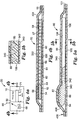
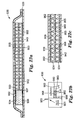
- useful non-retroreflective substrates include, but are not limited to, microstructured substrates having a series of channels therein such as in Figs. 8-10 , wherein the channels are linear, parallel, and closely spaced.
- the use of a retroreflective microstructured substrate may provide a number of advantages to the articles of the invention. These include the preferably highly visible fluid flow front with the use of the retroreflective substrate when the article is designed to be used in such a manner in which the fluid frustrates total internal reflection in the retroreflective substrate.
- the substrate and/or other materials used in the articles do not absorb the fluid, so as not to interfere with the fluid flow (i.e., the substrate and other components of the article, which the fluid may come in contact with, should preferably be essentially fluid impermeable, most preferably fluid impermeable).
- the substrate and/or other materials used in the article, which the fluid may come into contact with (such as the cover, for example) are essentially non-absorbent, most preferably non-absorbent with respect to the fluid with which they are used.
- the fluid flow is only through the channels of the substrate and there is essentially no diffusion, most preferably no diffusion, of the fluid into the substrate itself (or any other components of the article with which the fluid may come into contact).
- the fluid most preferably does not become absorbed, diffuse into, or permeate the substrate itself or other components of the article it may come into contact with.
- the flow of the fluid through the substrate is preferably via passive flow. That is, it should preferably be through capillary action and optionally, gravitational effects, although preferably any gravitational effects are minimal or nonexistent.
- the flow of the fluid should preferably not be "active", (i.e., caused by devices such as pumps, external vacuum sources, etc.).
- the substrate can have a number of different shapes.
- the substrate may be symmetrical or asymmetrical.
- the substrate may, for example, have a shape selected from the group consisting of rectangular, square, trapezoidal, ring, triangular, etc., shapes.
- a rectangular shape can be useful since it is easy to cut and it is easy to design an article having a rectangular shaped substrate.
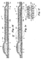
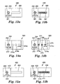
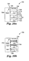
- the fluid flow rate decreases as the fluid progresses through the rectangular substrate. If time markings are desired on an article having a rectangular substrate (or any substrate for that matter in which the fluid flow rate decreases with time), typically they should not be evenly spaced due to the decreasing fluid flow rate. In such a case, the markings would typically be positioned closer together toward the end of the fluid flow path (See Figs. 1a and 3a , for example). In order to avoid this decrease in fluid flow rate and to have more evenly spaced time markings, one can potentially design the substrate such that its channels narrow near the end of the fluid flow path.
- the fluid would typically be positioned in a manner such that, upon activation, the fluid would contacts an edge or end of the substrate at a location where channel openings or inlets are present.
- typically channel openings are located on at least one edge or side of a substrate and the channels extend through the entire substrate surface to another end or edge of the substrate (typically an opposite end or edge).
- the components are typically positioned such that the flow path of the fluid corresponds with the longest side of the rectangle.
- the substrate is ring shaped
- the substrate of the article contains channels therein.
- the channels are interconnected.
- the channels are interconnected for a more even fluid flow front.
- the channels are typically provided on an exposed surface of the substrate.
- a substrate having internal channels can potentially be prepared by joining together two sheets, each sheet having a pattern on one side thereof
- the resultant substrate may or may not be retroreflective depending on the patterns joined together.
- the sheets can be joined together such that the patterned sides form a channel system through which the fluid can flow, typically via capillary action. These sheets can be held together by a variety of means such as by a clamp, a cover, an adhesive, hot-melt bonding, etc.
- an outer surface of the substrate contains the channels therein.
- An opposing outer surface of the substrate may optionally also contain channels. It is preferable, but not required, that the opposing outer surface be free of channels. It is typically expensive to provide a pattern on a substrate surface and it would not be cost effective to have channels on both surfaces when it is not necessary that both sides contain channels.
- the opposing outer surface of the substrate is flat and free of channels and bonded to a cover in such a manner as to avoid fluid flow between the cover and the smooth side of the substrate.
- the article should be constructed such that, upon activation, the fluid contacts the surface of the substrate that has channels therein in a manner such that the fluid can flow within the channels.
- fluid flow along only one microstructed surface of the substrate so as not to provide multiple fluid flow fronts, which could be confusing to an observer.
- multiple fluid flow fronts on the same substrate may be desirable.
- the channels of the microstructured substrate can have a variety of shapes. Typically the channels within the substrate are similarly shaped. Examples of useful channel cross-sectional shapes include, but are not limited to, the following: v-shaped channels, u-shaped channels, semi-circle-shaped channels, and square u-shaped channels.
- the channels when viewed from above, can be linear or non-linear. For example, they may be straight, curved, twisted, crooked, tortuous, etc.
- the channels may optionally be formed by a series of geometric projections, wherein the paths between the projections become the channels. This would be the case for retroreflective cube-corner sheeting discussed later herein.
- the channels of the substrate are planar.
- the depth of the channels ranges, from about 5 to less than about 1,000 microns, more typically about 10 to about 500 microns, preferably about 25 to about 200 microns, and most preferably about 25 to about 100 microns.
- the width of the channels ranges, from about 5 to about less than about 1,000 microns, more typically about 10 to about 500 microns, preferably about 25 to about 250 microns.
- the spacing of the channels is such that a channel is within about 5 to less than about 1,000 microns of another channel, more typically about 10 to about 500 microns, and preferably about 10 to about 250 microns.
- the shape, length, and number of channels on the substrate can vary depending on a number of factors. These include, for example, the length of time one desires for the fluid to run through the substrate, the fluid to be used with the substrate, and the level to which the fluid flow should or should not be influenced by forces other than capillary forces (such as gravity). To design an article substantially unaffected by gravity, one should preferably utilize a substrate with sufficiently small channels.
- the substrates useful according to the invention are microstructured.
- a variety of different classes and types of retroreflective and non-retroreflective channel-containing microstructured substrates are useful in embodiments of the invention.
- the microstructured substrate retains its geometry and surface characteristics upon exposure to the fluids used in the article of the invention.
- non-retroreflective substrates examples include, but are not limited to, those disclosed in U.S. Patent No. 5,728,446 (Johnston ) and U.S. Patent No. 5,514,120 (Johnston ). These substrates provide for liquid management films that facilitate desired rapid and uniform anisotropic or directionally dependent distribution of liquids and absorbent articles using these films. These liquid management films have at least one microstructured surface with a plurality of primary grooves to promote the unidirectional spreading of the liquids. These primary grooves may also contain secondary grooves as in U.S. 5,728,446 . However, these additional secondary grooves are less preferred for use in the current invention as they could contribute to a less even fluid flow front.
- the microstructured flow channels of non-retroreflective microstructured substrates are, in some embodiments, substantially parallel and linear over at least a portion of their length. In all substrate embodiments, however, the channels are preferably interconnected.
- the channels can be easily formed from thermoplastic materials by casting, profile extrusion or embossing, preferably by casting or embossing.
- the non-retroreflective microstructured substrates are preferably formed from any thermoplastic materials suitable for casting, profile extrusion, or embossing including, for example, polyolefins, polyesters, polyamides, poly(vinyl chloride), polymethyl methacrylate, polycarbonate, nylon, etc.
- Polyolefins are preferred, particularly polyethylene or polypropylene, blends and/or copolymers thereof and copolymers of propylene and/or ethylene with minor proportions of other monomers, such as ethylene/vinyl acetate.
- Polyolefins are preferred because of their excellent physical properties, ease of processing, and typically lower cost than other thermoplastic materials having similar characteristics.
- microstructured substrate can be cast from curable resin materials such as acrylates or epoxies, and cured by exposure to heat, ultraviolet (UV), or E-beam radiation.
- curable resin materials such as acrylates or epoxies
- UV ultraviolet
- E-beam radiation the microstructured substrates having retroreflective and/or other optical properties discussed in greater detail below can also be made by the procedures described above.
- Retroreflective substrates are retroreflective substrates. Retroreflective materials have the property of redirecting light incident on the material back toward its originating source. In situations where the retroreflective sheeting may need to flex or conform to a surface, a sheeting is preferably selected, which does so without sacrificing retroreflective perforance.
- Microsphere-based sheeting sometimes referred to as "beaded” sheeting, is well known in the art and employs a multitude of microspheres, typically at least partially embedded in a binder layer and having associated specular or diffuse reflecting materials (e.g., pigment particles, metal flakes or vapor coats, etc.) to retroreflect incident light.
- specular or diffuse reflecting materials e.g., pigment particles, metal flakes or vapor coats, etc.
- retroreflectors are disclosed in U.S. Pat. No. 3,190,178 (McKenzie ), U.S. Pat. No. 4,025,159 (McGrath ), and U.S. Pat. No. 5,066,098 (Kult ).
- Microsphere-based sheeting does not have a regular predetermined channel pattern and is not considered to be "a substrate, the substrate having a microstructured surface, wherein the microstructured surface defines a plurality of channels" as that term is used herein.
- Basic cube-comer retroreflective sheeting is well-known to those of ordinary skill in the retroreflective arts and falls within the definition of "a substrate, the substrate having a microstructured surface, wherein the microstructured surface defines a plurality of channels" as used herein.
- a substrate the substrate having a microstructured surface, wherein the microstructured surface defines a plurality of channels
- Such sheetings are frequently used on road signs, safety garments and the like.
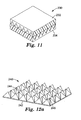
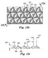
- the sheeting comprises a substantially planar base surface and a structured surface comprising a plurality of cube-comer elements opposite the base surface.
- Each cube-comer element comprises three mutually substantially perpendicular optical faces that intersect at a single reference point, or apex.
- the symmetry axis also called the optical axis, is the axis that extends through the cube-comer apex and forms an equal angle with the three optical surfaces of the cube-corner element.
- Cube-comer elements typically exhibit the highest optical efficiency in response to light incident on the base of the element roughly along the optical axis. The amount of light retroreflected by a cube-comer retroreflector drops as the incidence angle deviates significantly from the optical axis.
- Retroreflective sheeting design the retroreflective sheeting to exhibit its peak performance in response to light incident on the sheeting at a specific angle of incidence.
- the term "entrance angle” is used to denote the angle of incidence, measured from an axis normal to the base surface of the sheeting, of light incident on the sheeting. See, e.g. ASTM Designation: E 808-93b, Standard Practice for Describing Retroreflection.
- Retroreflective sheeting for signing applications is typically designed to exhibit its optimal optical efficiency at relatively low entrance angles (e.g. approximately normal to the base surface of the sheeting). See, e.g. U.S. Pat. No. 4,588,258 to Hoopman.
- U.S. Pat. No. 4,349,598 to White discloses a retroreflective sheeting design wherein the cube-comer elements comprise two mutually perpendicular rectangular faces disposed at 45 degrees to the cube-comer sheeting base and two parallel triangular faces perpendicular to the rectangular faces to form two optically opposing cube-comer elements.
- U.S. Pat. No. 4,895,428 to Nelson et al. ('428 patent) and U.S. Pat. No. 4,938,563 to Nelson et al.
- the cube-comer elements comprise two nearly perpendicular tetragonal faces and a triangular face nearly perpendicular to the tetragonal faces to form a cube-comer.
- the cube-comer elements further include a non-perpendicular triangular face. All of the aforementioned cube-comer sheetings would be expected to be useful in the articles of the present invention
- the manufacture of retroreflective cube-comer element arrays is typically accomplished using molds made by different techniques, including those techniques known as pin bundling and direct machining. Molds manufactured using pin bundling are made by assembling together individual pins that each have an end portion shaped with features of a cube-comer retroreflective element.
- U.S. Pat. No. 3,632,695 (Howell ) and U.S. Pat. No. 3,926,402 (Heenan et al. ) disclose illustrative examples of pin bundling.
- the direct machining technique also known generally as ruling, comprises cutting away portions of a substrate to create a pattern of grooves that intersect to form structures including cube-corner elements.
- the grooved substrate is typically used as a master mold from which a series of impressions, i.e., replicas, may be formed.
- the master itself may be useful as a retroreflective article. More commonly, however retroreflective sheeting or retroreflective articles are formed in a polymeric substrate using the master mold or using replicas of the master mold.
- Direct machining techniques are a useful method for manufacturing master molds for small microcube arrays. Small microcube arrays are particularly beneficial for producing thin retroreflective sheeting that has improved flexibility. Microcube arrays are also more conducive to continuous manufacturing processes. The process of manufacturing large arrays of cube-corners is also relatively easy using direct machining methods rather than pin bundling or other techniques.
- An illustrative example of direct machining is disclosed in U.S. Pat. No. 4,588,258 (Hoopman ).
- Master molds suitable for use in forming cube-corner sheeting in accordance with the '598 patent, the '428 patent, and the '563 patent may be formed using direct machining techniques as described above.
- the cube-corner geometries disclosed in these patents require two different machining tools to produce a master mold. This reduces the efficiency of the master mold manufacturing process.
- master molds manufactured according to these patents comprise surfaces that extend substantially perpendicular to the base surface of the master mold. Such perpendicular surfaces can be detrimental to the process of producing exact replicas of the master mold.
- the substrates useful according to the invention may optionally have one or more of the following optical characteristics: retroreflectivity, total internal reflection, and partial internal reflection. These include refractive and/or diffractive properties, for example.
- the microstructured substrate itself can have specular or diffusive properties to improve the detectability of the fluid as it moves on the microstructured substrate. As the fluid moves on the microstructured substrate, it wets the microstructured surface, causing the refractive index difference between the microstructured surface and adjacent fluid to decrease (compared to air), resulting in frustration of the optical characteristics of the microstructured substrate and improving its transparency.
- a variety of fluids are useful according to the present invention. Examples thereof include, but are not limited to, those selected from the group consisting of viscous fluids, viscoelastic fluids, and mixture thereof.
- the surface tension of the fluid can vary. Typically the surface tension of the fluid at 23 °C ranges from about 10 x10 -3 N/m to about 80 x10 -3 N/m, preferably about 10 x10 -3 N/m to about 60 x10 -3 N/m, even more preferably about 10 x10 -3 N/m to about 50 x10 -3 N/m, and most preferably about 10 x10 -3 N/m to about 40 x10 -3 N/m.
- the density of the fluid can vary. Typically the density of the fluid at 23 °C ranges from about 0.5 to about 2 grams/cc, preferably about 0.5 to about 1.5 grams/cc, and most preferably about 0.8 to about 1.5 grams/cc.
- the zero rate shear viscosity of the fluid can vary. Typically the zero rate shear viscosity of the fluid at 23 °C ranges from about 1x10 -3 to about 1x10 -6 Pa ⁇ s, preferably about 0.1 to about 1x10 5 Pa ⁇ s, and most preferably about 1 to about 10,000 Pa ⁇ s.
- the fluid selected is preferably temperature sensitive.
- the fluid selected is preferably substantially temperature insensitive, most preferably temperature insensitive.
- Temperature sensitive fluids are defined as having an activation energy (E a ) of 3 kcal/mole or more and a Q 10 of preferably greater than 1.1.
- Temperature insensitive fluids are defined as having an E a of less than 3 kcal/mole and preferably a Q 10 of 1.1 to 1.0.
- the fluid selected for use in an article of the invention is preferably innocuous and non-reactive with the other components of the article with which it may come in contact. If the article is to be used in contact with food products, it should meet all relevant laws and regulations for such a product.
- useful relatively innocuous and non-reactive fluids include, but are not limited to, the following: silicone fluids such as polydimethylsiloxane fluids, saturated hydrocarbon-based oils, silicone oils and gums, mineral oils, glycerols, water, and aqueous based fluids.
- the fluid may or may not be colored depending on the embodiment employed.
- the fluid is typically clear and colorless and, as the fluid fills the channels, it causes the total internal reflection to become frustrated (that is the substrate that appeared opaque now appears clear in those areas where the channels are filled, allowing a viewer to observe the colored cover layer below).
- the fluid has an index of refraction within about 0.4 of the index of refraction of the microstructured substrate surface (preferably the entire microstructured substrate) more preferably substantially the same, and most preferably the same as the microstructured substrate (preferably the entire microstructured substrate).
- the exact nature of the fluid can vary as long as, when it is used in an application where it is intended to render the substrate transparent, it does so sufficiently so one can identify the fluid flow front by, for example, viewing any color and/or graphics beneath the substrate.
- the substrate is not retroreflective.
- the fluid typically contains at least one pigment and/or at least onedye (such as blue organic dye, for example) and the substrate is selected to provide a contrast to the fluid flow (such as a white opaque substrate, for example).
- the selection of the fluid and the substrate and the positioning thereof in the article should be sufficient to allow an observer to view the progress of the fluid over time as it migrates through the channels of the substrate.
- an observer may find that the fluid is more readily visible by changing the viewing angle.
- Suitable fluids according to the present invention include, for example, viscoelastic and viscous fluids and combinations thereof that provide the desired properties for migration into the channels of the microstructured surface in response to time and/or cumulative thermal exposure.
- the surface energies of the article components should preferably cause the local contact angle of the fluid on the microstuctured surface of the substrate to be less than about 90 degrees, more preferably less than about 25 degrees, within the range of intended use temperatures.
- the contact angle is a function of the surface energy of the microstructured surface, the surface energy of the fluid (e.g. liquid), and the interfacial energy between the two.
- a viscous material can be defined by analogy to classic viscous fluids. If an external stress is applied to a viscous fluid, it will deform and continue to deform as long as the stress is present. Removal of the stress will not result in a return of the fluid to its undeformed state. Such a response is called viscous flow and defines a viscous material or fluid. When there is a direct proportionality between the stress and the rate of deformation in a viscous fluid, the fluid is a Newtonian fluid. There are also viscous fluids that are non-Newtonian and which exhibit a non-linear dependence between the stress and the rate of deformation.
- Viscoelastic materials Materials that exhibit both elastic and viscous properties simultaneously are called viscoelastic materials. Elastic properties can be explained with reference to classic elastic solids. Elastic solids respond to external stress by deforming and, upon removal of the stress, respond by returning to their original shape. Such a response is called elastic. Some elastic materials exhibit a direct proportionality between the stress and the deformation, thereby conforming to what is known as Hooke's Law. There are also elastic materials that do not obey Hooke's Law and that exhibit a non-linear relationship between stress and deformation.
- Viscoelastic materials are sometimes classified as either viscoelastic solids, i.e., elastic solids that exhibit some viscous effects during deformation, or viscoelastic liquids, i.e., viscous liquids that exhibit some elastic effects.
- a viscoelastic liquid can be identified as a viscoelastic material that continues to deform indefinitely when subjected to a shearing stress.
- a viscoelastic material may exhibit a transition from an immobile, glassy state to a viscoelastic liquid state at a temperature known as the glass transition temperature, Tg. It may also exhibit a transition from a partially crystalline state to an amorphous state at the temperature at which the crystalline material melts, T m. Often, such a material will behave as a viscoelastic solid below T m .
- Tg glass transition temperature
- a viscoelastic liquid exhibiting small elastic effects, such that it behaves essentially as a viscous fluid in a liquid state at all anticipated temperatures to which the article of the invention will be exposed.
- the fluid is preferably in a liquid state (most preferably a viscoelastic liquid state) at all anticipated temperatures to which the object to be monitored and, thus, the article of the invention will be exposed.
- a liquid state most preferably a viscoelastic liquid state
- This can be accomplished by choosing a fluid that has all such thermal transitions at temperatures below the anticipated range of temperatures to which the object to be monitored and, thus, the article of the invention will be exposed.
- This allows for an indicator that will be in its activated state upon contacting the fluid with the microstructured channels of the substrate. This also allows the fluid to migrate into the channels throughout the entire anticipated temperature range.
- the indicator will be able to provide continuous integration of time-temperature exposure over the entire range of temperatures to which the object to be monitored and, thus, the article of the invention is to be exposed. It is also preferable that the fluid be able to migrate into the channels at any temperature at which appreciable degradation or other change can occur in the product being monitored.
- viscoelastic liquid materials are preferred in the present invention, it is possible for some viscoelastic solid materials to function, provided the modulus of the material is low enough for it to deform and penetrate entirely through the microstructured channels under the influence of capillary action or other driving forces present in the device. These solids that can function as fluids by flowing within the channel substrates are considered to fall within the definition of "fluid" as used herein.
- a solid such as a viscoelastic solid, for example
- a crystalline or glassy continuous phase would not perceptively migrate into the channels, or if it did, it would be at such a slow rate as to not be practical for providing a visual indication of cumulative thermal exposure.
- temperatures above the crystalline melting point or the glass transition temperature of the material it would become a fluid and capable of migrating in the channels.
- Such materials are desirable for certain types of temperature monitoring applications, especially those in which the product undergoes degradation only above a critical threshold temperature.
- An illustrative, but by no means exclusive, list of viscoelastic and viscous materials that may be suitable for use in the articles of the present invention includes natural rubber; butyl rubber, polybutadiene and its copolymers with acrylonitrile and styrene; polyalpha-olefins such as polyhexene, polyoctene, and copolymers of these and others; polyacrylates; polychloroprene; polydimethylsiloxane; silicone oils and gums; mineral oils; and block copolymers such as styrene-isoprene block copolymers; and mixtures of any of the above.
- Materials that undergo a melting or glass transition to change from solid to liquid behavior and which could be useful in the present invention include hydrocarbon waxes, elastomer/tackifier blends, etc.
- the viscoelastic materials may, for example, comprise elastomers conventionally formulated as pressure sensitive adhesives. Examples thereof include, but are not limited to, polyisoprene, atactic polypropylene, polybutadiene, polyisobutylene, silicone, ethylene vinyl acetate, and acrylate based elastomers and can typically include a tackifying agent and/or a plasticizing agent.
- Monomers useful in making fluids useful in the articles of the invention include, but are not limited to, those that have a homopolymer glass transition temperature less than about 0°C.
- Useful alkyl acrylates include, but are not limited to, unsaturated monofunctional (meth)acrylic acid esters of non-tertiary alkyl alcohols having from 2 to 20 carbon atoms in the alkyl moiety, preferably from 4 to 18 carbon atoms, and more preferably from 4 to 12 carbon atoms.
- alkyl acrylate monomers include, but are not limited to, n-butyl acrylate, hexyl acrylate, octyl acrylate, isooctyl acrylate, 2-ethylhexyl acrylate, isononyl acrylate, decyl acrylate, dodecyl acrylate, lauryl acrylate, octadecyl acrylate, and mixtures thereof.
- An example of an optional reinforcing co-monomer is a monoethylenically unsaturated monomer having a homopolymer glass transition temperature greater than about 25 °C and is preferably co-polymerized with the acrylate monomers.
- Examples of useful co-polymerizable monomers include, but are not limited to, meth(acrylic) acid, N-vinyl pyrrolidone, N-vinyl caprolactam, substituted (meth)acrylamides such as N,N,-dimethyl acrylamides, acrylonitrile, isobornyl acrylate, and mixtures thereof
- the alkyl acrylate is typically present in the composition in amounts from about 50 to 99 parts by weight and the co-polymerizable monomer is typically present in corresponding amounts from 50 to 1 parts by weight, wherein the total amount by weight is 100.
- the elastomer can optionally include a tackifier and/or plasticizer in a tackifier to elastomer base weight ratio or a plasticizer to elastomer base weight ratio of typically up to about 2:1.
- Suitable tackifiers include, but are not limited to, hydrogenated rosin esters commercially available as Foral 85 TM , Foral 105 TM , or Abitol TM E and hydrocarbon tackifiers such as Regalrez TM , all available from Hercules Incorporated of Wilmington, DE.
- Suitable plasticizers include, but are not limited to, hydrocarbon oils such as Shellflex TM (available from Shell Chemical Co., Houston, TX), USP grade mineral oil, and phthalates including alkyl phthalates such as dioctyl phthalate, diisononyl phthalate, and allyl phthalates.
- the article of the invention is preferably designed to provide sufficient fluid to fill the channels of the microstructured surface as the fluid migrates along the channels.
- the article components should also preferably be chosen to provide a desired rate of migration of the fluid into the channel structure of the microstructured substrate.
- the fluid such as a viscous liquid, for example, should preferably migrate through this channel structure at a rate that is essentially independent of temperature.
- the indicating device can be constructed to provide a visually observable indication of the time expired. Accordingly, it is desirable to be able to select a liquid having suitable characteristics for the amount of time that needs to be monitored.
- the fluid such as a viscoelastic liquid for example, preferably migrates through the channel structure at a rate that preferably increases with temperature in a sufficiently similar way to the change in decay rate of the object to be monitored to provide a suitable time-temperature indicator.
- the indicating device can be constructed to provide a visually observable indication of a predetermined cumulative thermal exposure. It will often be useful to provide an indication of a predetermined allowable cumulative thermal exposure for a particular perishable item, such as food, medicine, photographic supplies, and vaccines. Accordingly, it is desirable to be able to select a fluid having suitable characteristics for the particular product to be monitored.
- Q 10 and E a are useful as a quantification of rate of degradation or other rate of change of an object to be monitored. It is also useful to quantify the effective E a or Q 10 of the fluid so as to select a suitable fluid for the object to be monitored. As with the particular object to be monitored, it is possible to select various fluids and perform experiments on indicators comprising the fluids to determine the rate of change of the visually observable indication at various temperatures for each fluid. It is then possible to calculate a measured effective E a and/or Q 10 for various fluids with a given substrate to best fit the intended use of the indicator. It is also possible to measure the temperature dependence of the flow properties of the fluid independently and estimate the effective activation energy.
- the temperature dependent shift factors that result can be fit to the Williams-Landel-Ferry equation and the effective activation energy can then be calculated according to the well-known equation of Ferry. See John D. Ferry, Viscoelastic Properties of Polymers, (John Wiley and Sons, Inc, 1980 ).
- One skilled in the art of rheology would be able to use the equation of Ferry as described. Any of a number of other rheological properties could be measured such as creep compliance, dynamic viscosity, etc. and their temperature dependence could be used by one skilled in the art of rheology to estimate the effective activation energy.
- An effective E a over a given temperature range can be calculated for each fluid.
- the fluid can then be chosen to provide an indication of a predetermined thermal exposure for a given object to be monitored.
- One skilled in the art of rheology can readily determine the E a or Q 10 for a particular fluid.
- the runout time This is the period of time it takes for migration of the fluid to fill the channels of the microstuctured surface and provide the visually observable indication. This is the point at which the leading front (i.e. the fluid flow front) of the migrating fluid reaches a predetermined distance along the channels of the microstructured surface.
- the fluid selected, the characteristics of the channels formed by the microstructured surface, and the length of these channels can affect the runout time of a particular indicator.
- the fluid is preferably in its amorphous liquid state to at least below 50 °C, more preferably below 20 °C, still more preferably below 0 °C, yet more preferably below -20 °C, and most preferably to at least below -40 °C.
- the fluids described herein typically have glass transition temperatures falling within a range of from about -130 °C. to 10 °C. Some of the fluids described herein remain useable to temperatures at least as high as 100 °C, and it may be possible to formulate materials useful to temperatures as high as 200 °C or higher.
- the fluid should remain separated from the substrate until activation of the article is desired.
- a manipulation is typically performed on the indicator such that the fluid is allowed to contact at least some of the channels of the substrate.
- the article Prior to activation, the article can be stored almost indefinitely.
- the fluid may be separated from the substrate, for example, by an actual physical barrier or by merely a space. The separation by merely space is useful for an article that may be a movement indicator that activates when the article is moved by lifting, tilting, and/or inverting, for example, thereby placing the fluid in contact with the substrate channels.
- an actual physical barrier is advantageous for articles that one wishes not to become activated merely by the position of the article and requires an actual step such as penetrating, rupturing, or removing the barrier, for example, to allow fluid contact with the substrate.
- a number of fluid barriers may be used according to the invention.
- the barrier could be a reservoir or container such as a pouch, sack, or bladder in which the fluid is contained. Upon applying pressure to the pouch, sack, or bladder it would rupture allowing contact of the fluid with the substrate. This pressure may be applied by finger pressure, for example.
- Other barriers include, for example, gates, valves, etc.
- barriers could be manipulated or removed, for example, by pulling a tab, pulling a cord,-removing a laminated seal, breaking a capsule, etc. to allow contact of the fluid with the substrate.
- Other fluid reservoirs and barrier systems and methods of activation would be useful in the articles of the invention.
- the barrier could be made from a number of materials including but not limited to plastics, adhesives, metals, glass, etc.
- each separate fluid may be contained by a separate barrier.
- portions of the same fluid may each be contained by a separate barrier.
- a solid that becomes a fluid upon exposure to heat it may be separated from the substrate by one of the barriers described above, for example.
- the solid could be positioned such that, instead of contacting the substrate immediately upon melting, it is separated from the substrate by a space and does not contact the substrate until movement of the article occurs.
- the article of the invention may optionally include a covering which covers a portion or all of the article.
- a covering would typically cover a portion or all of any fluids, any solids, any barriers and the substrate or substrates.
- the covering would typically also cover any colored or ink layers that are contained in the article and that are intended to X gradually appear and disappear, when viewed as the fluid flow progresses.
- the covering of the article may be flexible, semi-rigid or rigid.
- the covering is preferably chosen such that it does not interfere with the activation of the article and the flow of the fluid or fluids along the fluid flow path or paths.
- the covering preferably should be selected to prevent fluid or fluids from leaking from the article.
- the covering can be made from a variety of materials, including, but not limited to, polymeric materials such as plastics.
- the covering may be a one-piece construction or may be a multiple-piece construction formed, for example, by two pieces of tape joined together.
- the cover could be made of an opaque material provided with a transparent window through which to view the fluid progress, for example.
- the cover may be made from a transparent material with graphics thereon. A portion of the transparent cover should preferably be left free from graphics to provide a window to view the fluid progression.
- Other cover configurations are also possible.
- the cover may be adhered to the substrate and other components of the article such as a fluid reservoir, for example, in a variety of ways including, for example, lamination of a pressure sensitive adhesive tape onto the substrate and the fluid reservoir such that the tape backing becomes the cover.
- a transfer pressure sensitive adhesive can be laminated to the substrate and a fluid reservoir, for example, and a cover can be laminated to the pressure sensitive adhesive.
- the Grey Time One of the disadvantages of many presently known timers and time-temperature indicators is the effect known as "The Grey Time”. Since many of these known indicators rely upon image appearance or color change, rather than a fluid flow front, to monitor the passage of time or the accumulated thermal history of the indicator, there is a period where the status of the indicator is subject to interpretation by the viewer. For example, for a known indicator that has an area to be monitored that simultaneously changes in its entirety from white to black goes through a period where the indicator becomes increasingly grey. The point where the indicator moves from the grey state to the black state, even if a reference color chart is placed on the indicator, is subject to interpretation of the viewer and, therefore, lacks a sharp transition time.
- This phenomenon is also present to some degree in similarly designed known indicators where a hidden message appears or a readable message disappears because all of these indicators are based upon diffusion.
- the present invention uses a substrate with well defined channels that may be precisely and reproducibly made and, therefore, fluid flow through these channels is preferably accurate and reproducible.
- the indication of the passage of time in the article of the current invention is provided by a fluid flow front.
- the readily detectable presence or absence of a fluid in the substrate channels minimizes "The Grey Time” phenomenon discussed above.
- the fluid flow in an article of the invention can be viewed by an observer with an unaided eye (when the viewer has 20/20 vision or vision corrected to 20/20 vision).
- the fluid flow may be monitored continuously during operation of the article (See Figs. 1a-c , for example) or the fluid flow may be monitored at discrete and predetermined sections of the article through the use of small windows, slots, or other similar types of viewing apertures (See Figs. 2 and 14a-b , for example).
- a small window at the location on the substrate corresponding to the passage of that period of time may be all that is desired.
- continuous monitoring of time or an indication of the time remaining until a milestone time is reached may be desirable. In that case several small windows or one larger window may be desirable for monitoring fluid flow.
- a fluid to be used therewith most likely would contain dyes, pigments, and/or other coloration agents. As the fluid flows through the channels, the color-containing fluid front may be visually detected by contrast with, for example, a white substrate (See, for example, Figs. 5a and 5b ).
- the progress of the fluid flow can optionally be monitored by observing the loss of total internal reflection in the retroreflective substrate as the fluid progresses through and fills the substrate channels.
- the presence of the fluid in the channels in close physical contact with the optical surface of the retroreflective substrate destroys the air interface necessary for total internal reflection to occur at the optical surface.
- the total internal reflection is frustrated and the otherwise opaque channel containing substrate becomes transparent.
- a backing behind the retroreflective substrate can be colored to enhance the contrast between the regions where total internal reflection has been frustrated and regions where total internal reflection is operating or a message or messages including, for example, a bar coded message, may be printed on the backing to be revealed as the fluid flow progresses and the total internal reflection is frustrated (See, for example, Figs. 1e and 1f ).
- the concept of frustration of retroreflection is discussed in U.S. Patent No. 5,959,777 and U.S. Patent No. 5,999,307 .
- the article of the invention may optionally comprise a number of graphics. These may include, for example, an identification of what the article is and by whom the article is made, instructions on how to activate the article, and scales to help show the progress of the flow of fluid or fluids over time and, thus, the amount of time elapsed.
- the units on the scale may be indicative of seconds, minutes, hours, days, weeks, months or years, for example, depending on the length of time the article is designed to be used for.
- the scale could include symbols indicative of the elapsed time such as a plus, zero and minus along the fluid flow path, wherein a plus indicates much time remaining, zero represents a mid-point, and a minus indicates an end point.
- these graphics would, in some cases, be applied to the covering of the article adjacent to the window or windows or even on the window or windows through which the fluid flow is viewed along the fluid flow path.
- the inside cover of the backing beneath the substrate or the side of a substrate opposite the side having fluid flow therethrough could have a scale printed thereon.
- a separate printed and/or graphics layer could be positioned on a side of a substrate opposite of the fluid flow such that it becomes apparent to an observer with fluid flow.
- transparent layers such as an adhesive layer, could be used to bond such a layer to the substrate.
- symbols, a scale, words such as “expired”, “end”, “finished”, “replace”, and “remove” etc.), etc. could be printed on the inside of the backing and appear to a viewer as the fluid progresses along the channels of a retroreflective substrate.
- Other uses and positioning of color, ink, and graphics are possible.
- graphics may appear on the article such that they remain during fluid flow, only become apparent with fluid flow, and/or vanish with fluid flow.
- a non-structured surface of a substrate may have the word "fresh” printed on the substrate side opposite the channels.
- a colored fluid passing through the channels slowly obscures the word "fresh''.
- a structured substrate surface would typically be positioned closest to the window.
- the articles of the invention can be used for a variety of purposes.
- the timer has the following potential uses. It can be used on items that are subject to degradation over time such as food, beverages, pharmaceutical products such as vaccines, medicines, vitamins, etc. It can also be used on or in conjunction with items that need to be replaced on a regular basis as a reminder that sufficient time has elapsed such that a replacement should be made. These items include, for example, filters, such as furnace filters and water filters; automotive oil; cleaning sponges; etc. These articles can also be used to time activities such as meetings, "time-outs" for children, medical tests, etc. The articles can also be used as a reminder for taking medicine or changing bandages, etc.
- a potential use of a timer article would be on a transdermal patch that is intended to release a drug, such as a painkiller for example, through the skin of a patient.
- the timer article could be used to indicate when the patch had expired and needed to be replaced. Care should be taken that such articles are adequately tested before being used for medical, health, and/or safety uses and that they comply with all relevant laws and regulations.
- the timers could also be used on or in conjunction with parking permits, admission tickets, and visitor identification badges that are to have a set expiration time or date; game pieces; lottery tickets; invitations; calendars; announcements; greeting cards; reminders to clean, toss contents, change batteries; etc.
- the article could potentially be attached to an article to be monitored, such as a food item, carried by the user or positioned elsewhere, such as in a notebook, on a bulletin board, counter, car dashboard, etc.
- game pieces, lottery tickets, invitations, announcements, and greeting cards may not have a scale that marks time passage on them, they could be designed to elapse in a certain period of time. Typically it would be long enough to build suspense (seconds or minutes), but not so long that the user of the article becomes bored waiting for the full message.
- the articles of the invention are particularly useful for items where it would not be appropriate or feasible to use conventional timing devices. These timer articles could be applied, for example, by a consumer to packages of leftover food in a refrigerator. Timer articles could also be applied, for example, by a manufacturer, to packages of food that retain their freshness, for example, seven days upon opening. The consumer could then activate the article upon opening.
- Fig. 1a illustrates a timer article 2 of the invention.
- the article 2 includes cover 4.
- Cover 4 contains printing thereon except for a rectangular section identified as 8, which is left transparent to provide a window so a viewer can observe the fluid flow upon activation.
- the printing on the cover 4 also includes scale 7, activation point 6, and activation instructions 5.
- Fig. 1b is identical to Fig. 1a , except that activation has already occurred.
- a colored bar 10 shows the elapse of time.
- the edge of the bar 10, which moves over time, is identified as 300 and is also known as the fluid flow front.
- Fig. 1c is identical to Fig. 1b except that the colored bar 10 indicates that there is no more time left to run on the timer article 2.
- Fig. 1d is a cross-sectional view of the article of Fig. 1a taken along line 1d-1d.
- a pouch identified as 3 contains the fluid 5.
- the dot, which marks the activation pressures point, is identified as 6.
- Cover 4 includes a single-sided adhesive tape that forms the top of the cover 4 and includes a film layer 319 and an adhesive layer 15.
- a layer of microstructured substrate 7 is sandwiched within the cover 4 adjacent to the pouch 3.
- the unstructured surface of the substrate 7 is identified as 305 and is positioned closest to the window 8.
- the opposite structured surface of the substrate 7 is identified as 309.
- Fig. 1e is a cross-sectional view of the article of Fig. 1b .
- the pouch 3 has been ruptured to allow the flow of fluid 5 into the channels of the structured surface 309 of the substrate 7.
- the bottom of the cover 4 includes a double-sided adhesive tape.
- a release liner 21 is positioned on the side of the double-sided adhesive tape farthest away from the substrate 7.
- the double-sided adhesive tape includes film layer 11 and adhesive layers 17 and 19.
- a slight separation identified as 33 exists between the upper and lower layers of the cover 4. The separation provide a means of escape for the air within the substrate 7 channels, which is displaced as the fluid 5 fills and moves along the channels of the substrate 7.
- Fig. If is an enlarged cross-sectional view of a portion of the timer article 2 of Fig. 1e .
- the enlargement shows the path of light rays 402 that impinge upon the portion of the substrate 7 where the fluid is not present. Since fluid does not fill the channels of the retroreflective substrate 7, the rays 402 internally reflect and the substrate 7 appears opaque.
- Fig. 2 is an alternate embodiment of a timer.
- the article 20 includes cover 24.
- Cover 24 contains printing thereon except for three circular sections 26 a-c, which are left transparent so a viewer can observe the fluid flow upon activation.
- the printing on the cover 4 also includes activation pressure point 22 and activation instructions 23.
- a plus sign 25a, a zero 27a, and a minus sign 29a appear in windows 26 a-c respectively.
- the symbols 25a, 27a, and 29a are not visible prior to activation.
- As the fluid travels along the substrate first the plus sign 25a and color 25b appear, then the zero 27a and color 27b appear, and then the minus sign 29a and color 29b appear.
- the color and symbols appearing in each of the windows 26 a-c indicates that the timer 20 has expired.
- Fig. 3a is another embodiment of the article of the invention.
- the timer article 30 includes cover 34.
- Cover 34 contains printing thereon except for a rectangular section identified as 36, which is left transparent to provide a window so a viewer can observe the fluid flow upon activation.
- the printing on the cover 34 also includes activation pressure point 32, activation instructions 31, and scale 39.
- the elapse of time is shown by colored bar 38 having fluid flow front 302 and the letters 40, which appear as time progresses.
- Fig. 3b is identical to Fig. 3a except that time has run out on the timer article 30 as evidenced by the colored bar 38 that fills the window 36 and the extra indication provided by the word "expired" 40 that appears in the window 36.
- Fig. 4a is a timer article of the invention identified as 50.
- the cover 58 that has printing thereon contains a transparent portion that forms a window 70 that allows a viewer to view the travel of the fluid and, thus, the passage of time.
- the cover 58 also includes a scale 71, activation instructions 68, and a pull tab 66 that serves to activate the article 50 by removing the barrier (not shown in this figure) so that the fluid can contact the substrate 60 and fill and flow within its channels.
- Fig. 4b is a cross-sectional view of the article 50 of Fig. 4a taken along line 4b-4b.
- Reservoir 52 holds the fluid 54 until activation is desired.
- Barrier 53 can be removed to commence activation.
- the retroreflective substrate 60 is positioned adjacent to the barrier 53.
- the smooth unstructured surface of the substrate 60 is identified as 332.
- the structured surface of the substrate 60 is identified as 330.
- the upper layer of the cover 58 is a single-sided adhesive tape having printing thereon comprising film layer 59, adhesive layer 57, and printed layer 404.
- the lower layer of the cover 58 is a single-sided adhesive tape comprising film layer 64 and adhesive layer 56.
- a colored printed layer 62 exists between film layer 64 and adhesive layer 56.
- the printed layer 62 can be viewed by an observer through window 70 as the fluid 54 progresses through the substrate 60 channels, rendering increasing portions of the substrate 60 transparent over time.
- Fig. 5a is an alternate embodiment of a timer article of the invention shown in cross-section.
- the article 80 comprises pouch 84 containing fluid 86.
- the cover 406 comprises an upper layer and a lower layer.
- the upper layer of the cover comprises a single-sided adhesive tape with printing thereon.
- the single-sided adhesive tape comprises film layer 340, adhesive layer 88, and printing 408.
- the lower layer of the cover comprises a single-sided adhesive tape comprising film layer 343 and adhesive layer 342.
- the liquid 86 in this embodiment is colored and forms a contrasting image as it travels along the substrate 106.
- the liquid 86 flows within a series of parallel v-shaped channels 82 in the upper surface of the substrate 106.
- a slight separation identified as 101 exists between the upper and lower layers of the cover 406.
- the separation 101 provides a means of escape for the air within the substrate 106 channels that is displaced as the fluid 86 moves along the substrate 106.
- Fig. 5b is a cross-sectional view of the article of Fig. 5a , taken along line 5b-5b, which more clearly shows the liquid 86 flowing through the parallel v-shaped channels of the substrate 106.
- Fig. 6 is a cross-sectional view of another embodiment of the timer article of the invention.
- the article 110 includes one-piece unit 120 that includes a microstructured retroreflective surface 128 adjacent to a fluid reservoir 122 that contains fluid 124.
- a weak adhesive 130 serves as a barrier between the reservoir 122 and the structured surface 128 until activation.
- a layer of laminating adhesive 126 is positioned against the open side of the fluid reservoir 122, the barrier 130, and the microstructured surface 128.
- a layer of ink 127 is on an opposite side of the laminating adhesive 126. The ink 127 becomes visible upon activation of the article as the fluid begins to fill the voids within the retroreflective microstructured surface 128.
- the layer of ink 127 is printed on a single-sided adhesive tape comprising film layer 132 and pressure sensitive adhesive layer 121. Graphics 123 appear on the smooth top side of the one-piece unit 120. A sufficient portion of the unit 120 is left free of graphics to provide a window through which an observer can view the fluid flow.
- Fig. 7a is another embodiment of the article of the invention.
- the article 150 includes a cover 151.
- the outer perimeter of the window 152 is identified as 155 and the inner perimeter of the window is identified as 153.
- the cover 151 contains a scale 158.
- Fig. 7b is identical to Fig. 7a except that the article has been activated and the colored ring 160 is indicative of the fluid flow.
- the fluid flow front is identified as 162.
- Fig. 8 illustrates a microstructured substrate 180 that is useful in an article of the invention.
- the substrate 180 has a series of parallel v-shaped channels 184.
- the peaks of the substrate 180 are identified as 182. Since the substrate 180 is not retroreflective, it would be used in a manner wherein a contrasting fluid flows through the channels of the substrate 180 such that the fluid is between the window of the article and the substrate 180.
- the substrate 180 is the same as the substrate 106 that is present in the article of Figs. 5a-5b .
- the channel width is identified as 181 and the channel depth is identified as 183.
- Fig. 9 illustrates a microstructured substrate 201 that is useful in an article of the invention.
- the substrate 201 has a series of square u-shaped channels.
- the bases of the channels are identified as 203.
- the sides of the channels are identified as 202. Since the substrate 201 is not retroreflective, it would be used in a manner wherein a contrasting fluid flows through the channels of the substrate 201 such that the fluid is between the window of the article and the substrate 201.
- the channel width is identified as 204 and the channel depth is identified as 205.
- Fig. 10 illustrates a microstructured substrate 220 that is useful in an article of the invention.
- the substrate 220 has a series of semi-circle-shaped channels.
- the bases of the channels are identified as 222.
- the sides of the channels are identified as 224. Since the substrate 220 is not retroreflective, it would be used in a manner wherein a contrasting fluid flows through the channels of the substrate 220 such that the fluid is between the window of the article and the substrate.
- the channel width is identified as 223 and the channel depth is identified as 225.
- Fig. 11 illustrates a microstructured substrate 230 wherein the microstructured surface that the liquid is to migrate through and fill is internal to the substrate 230 and is formed by microstructured film 232 and microstructured film 234 that are joined together at their microstructured surfaces.
- Fig. 12a illustrates a perspective view of a microstructured substrate that is useful in an article of the present invention.
- This microstructured substrate 240 that has a cube-corner pattern is a known material and is similar to the materials disclosed in U.S. Patent Nos. 5,691,846 ; 5,450,235 ; and 4,588,258 .
- the substrate 240 peaks are identified as 244 and the substrate 240 depressions, which form channels, are identified as 246.
- the smooth unstructured surface of the substrate 240 is identified as 242.
- Fig. 12b is a top plan view of the microstructured substrate of Fig. 12a .
- Fig. 12c is a cross-sectional view of the structured substrate of Fig. 12b taken along line 12c-12c.
- the depth of the channels is identified as 245.
- the widths of the wider channel portion are identified as 243 and the widths of the narrower channel portions are identified as 247. Even though the channels have differing widths in portions, the fluid flow front would still be relatively even due to the microstructured nature of the channels (that is, the regularity of the projections) and the interconnection of the channels, which help to regulate and maintain consistency of the fluid flow.
- Fig. 13a illustrates an article 290 of the invention that is designed as a game piece.
- the article 290 includes cover 294.
- Cover 294 contains printing thereon except for a rectangular section identified as 296 that is left transparent to provide a window so a viewer can observe the fluid flow upon activation.
- the printing on the cover 294 also includes activation point 292 and activation instructions 301.
- Fig. 13b is identical to Fig. 13a , except that activation has already occurred.
- a colored bar 297 and dollar amount of $1000 (298) appear after the designated timer period.
- Fig. 14a is an embodiment of a time/temperature indicator of the invention prior to activation.
- the article 260 includes cover 264.
- Cover 264 contains printing thereon except for three circular sections 274 a-c, which are left transparent so a viewer can observe the fluid flow upon activation.
- the printing on the cover 264 also includes activation pressure point 262 and activation instructions 272.
- Fig. 14b is identical to Fig. 14a except that activation has already occurred.
- a plus sign 266, a zero 268, and a minus sign 270 appear in windows 274 a-c respectively.
- the symbols 266, 268, and 270 are not visible prior to activation.
- Fig. 15a is another embodiment of an article of the invention that is designed as a furnace filter reminder.
- the article 400 includes cover 402, activation instructions 408, activation pressure point 406, and a transparent rectangular portion of the cover 404 through which an observer can view the flow of the fluid upon activation.
- Fig. 15b is identical to the article of 15a except that activation has occurred and enough time has elapsed that the reminder now indicates that it is time to change the filter.
- the color that appears in the window is identified as 411 and the instructions to "change filter" are identified as 410.
- Fig. 16 illustrates an exploded perspective view of another article of the invention.
- the timer article 420 includes a die-cut pressure sensitive adhesive layer 424 that contains a cut-out 422 that forms a fluid reservoir that contains fluid 421.
- the die-cut pressure sensitive adhesive 424 also includes a cut-out 426 that contains the microstructured substrate 427.
- a barrier 425 that is a very thin, rupturable section of the pressure sensitive adhesive layer 424 separates the fluid from the substrate 427.
- a laminating pressure sensitive adhesive 428 bonds the die-cut pressure sensitive adhesive 424 to a layer of ink 430 and laminates the structured side of the microstructured substrate 427.
- the opposite side of the ink layer 430 is bonded to a double sided pressure sensitive adhesive tape comprising adhesive layers 432 and 436 and film layer 434 therebetween.
- a single-sided adhesive tape comprising film layer 445, pressure sensitive adhesive layer 446 bonded to one side of film layer 445, and a graphics layer 424 printed on the opposite side of film layer 445 is bonded to die-cut pressure sensitive adhesive layer 424.
- the graphics layer 424 includes activation instructions 441, activation pressure point 440, and scale 443.
- a rectangular portion 442 of the transparent film 445 is left transparent to allow an observer to view fluid flow upon activation.
- Fig. 17a illustrates another embodiment of an article of the invention.
- the article 450 is a birth announcement.
- the cover 460 contains printing thereon except for an irregular shaped section 454 that is left transparent to view the flow of the fluid.
- the window and the substrate underlying the window both have essentially a backward s-shape.
- the window may be identical or substantially similar in shape to the substrate.
- the window may have a different shape than the substrate.
- the substrate is larger than the window.
- Activation instructions and pressure point are identified as 452.
- Fig. 17b is the same as Fig. 17a except that the article 450 has been activated and enough time has elapsed for the message 456 to come into view.
- the color in the window is identified as 455.
- Fig. 18a shows a top view of a portion of an another embodiment of an article 500, which includes cover 502 and a transparent portion 504 therein, which forms a window through which an observer can view the fluid flow along substrate 503.
- the colored bar that appears in the window is identified as 506.
- the fluid flow front is identified as 508.
- the variation in the fluid flow front is nonexistent.
- Fig. 18b shows a top view of a portion of another embodiment of an article 520 that includes cover 522 and a transparent portion 524 therein, which forms a window through which an observer can view the fluid flow along substrate 525.
- the colored bar that appears in the window is identified as 526.
- the fluid flow front is identified as 528.
- the variation 530 in the fluid flow front 528 is greater than in Fig. 18a .
- Fig. 18c shows a top view of a portion 540 of another embodiment of an article of the invention that includes cover 542 and a transparent portion 544 therein, which forms a window through which an observer can view the fluid flow along substrate 545.
- the colored bar that appears in the window is identified as 546.
- the fluid flow front is identified as 548.
- the variation in the fluid flow front is identified as 550. To read such a scale that has peaks, one would look at the mid-point in distance between the two farthest points along the fluid flow front in the direction of fluid flow. However, it is preferred that the fluid flow front contain minimal and small peaks, if any, preferably none.
- peaks are less esthetically pleasing and makes a scale more difficult to read. If the fluid flow front is a crescent shape having any peaks at all it is read using the method of Fig. 18c rather than Fig. 18b . Any other fluid flow fronts other than a pure crescent as shown in Fig. 18b or a uniform front as shown in Fig. 18a would also be read as in Fig. 18c .
- the fluid flow front has no meniscus, no peaks, and is even.
- the fluid flow front is most preferably a straight line as in Fig. 18a .
- the fluid flow front is preferably a symmetrical ring.
- the fluid flow front has a variation of less than about 5 mm, preferably less than about 4 mm, more preferably less than about 3 mm, even more preferably less than about 2 mm, and most preferably less than about 1 mm.
- Fig. 19a illustrates another embodiment of a timer article of the invention that would be useful as a timer for a home permanent kit in which a user is to apply a permanent solution followed by a neutralizer solution to their hair.
- the article actually includes two timers. The first is a permanent solution timer 604. The second is a neutralizer solution timer 612. Upon applying the permanent solution to ones hair, one would activate the permanent solution timer 604. Upon expiration of that timer 604 one would rinse off the permanent solution and apply the neutralizer solution to ones hair and then activate the neutralizer solution timer 612.
- the article 600 includes cover 606.
- Cover 606 contains printing thereon except for two rectangular sections, one of which is identified as 607, which is left transparent to provide a window so a viewer can observe the fluid flow upon activation of the permanent solution timer 604.
- the window 614 allows a viewer to observe the fluid flow upon activation of the neutralizer solution timer 612.
- the printing on the cover 606 also includes activation points 602 and 610 and timer identifications 604 and 612.
- Fig. 19b is identical to Fig. 19a except that activation of the permanent solution timer 604 has already occurred.
- a colored bar 620 and words 622 shows that the permanent solution timer 604 has expired.
- Fig. 19c is identical to Fig. 19b except that the neutralizer solution timer 612 has been activated and the color 630 and words 632 appearing in the window 614 indicate that the neutralization solution timer 612 has expired.
- the timers are designed to be activated consecutively and independently rather than concurrently.
- the substrates 609 and 611 are positioned far enough apart and the article designed such that fluid from one substrate does not flow onto the substrate of an adjacent timer. If one substrate is used for both fluid flow paths it should preferably be divided or somehow sealed in the center thereof to prevent fluid from crossing over into the adjacent fluid flow path.
- the permanent solution timer 604 and neutralizer solution timer 612 the same fluid is used but in separate reservoirs, for example in two separate pouches. Since for the permanent kit each solution is to remain separately on the hair for a different period of time each timer would be designed to expire at different time by selection of different substrates.
- the same fluid is used for both timer portions, but substrates having differing fluid flow rates are used.
- the same substrate type could be used for both timer portions as long as a different fluid is used for each timer portion, wherein each fluid would flow through the substrate at a different rate.
- both the fluid and the substrates could be selected to be different as long as the desired timing is achieved.
- Fig. 20a is a timer article of the invention identified as 700.
- the cover 705, which has printing thereon, contains three separate transparent portions that form windows 706, 712, and 720 respectively, which allow a viewer to view the travel of the fluid and, thus, the passage of time.
- the cover 705 also includes scales 710, 716, and 724, which are in hours, days and weeks, respectively, and which correspond to windows 706, 712, and 720, respectively; activation instructions 704; and a pull tab 702, which serves to activate the article 700 by removing the barrier (not shown in this figure) so that the fluid can contact the substrates 708, 714, and 722 and flow within their channels. The same fluid is used within this article embodiment.
- the adjacent substrates 708, 714, and 722 differ in configuration such that fluid flows through each of them at different rates.
- the article is also designed such that fluid cannot flow from one substrate onto another. This could be accomplished by the use of a fluid impermeable barrier between the substrates, for example.
- the article 700 is designed such that the fluid contacts each substrate upon activation of the article.
- Fig. 20b is identical to Fig. 20a except that activation has already occurred.
- a colored bar 730 shows that the four hour timer has elapsed.
- Colored bar 732 shows the elapse of two days via fluid flow front 734.
- Colored bar 736 shows also, via fluid flow front 738, that two days has elapsed, but in a fraction of a week.
- Such a timer article 700 could be used, for example, for reminder for medical procedures wherein a reminder is necessary after four hours, four days, and four weeks and wherein it would be difficult to note those reminders on a several week scale.
- Fig. 21 a illustrates a perspective view of a timer article 902 of the invention positioned on a box 900.
- the timer article 902 includes an opaque cover 906 that includes a transparent rectangular portion 908 through which one can view substrate 910 and fluid reservoir 918 that contains fluid 920.
- the fluid 918 is separated from substrate edge 912 by space 916.
- the article 902 remains inactivated. Activation occurs when box 900 becomes inverted, as in Fig. 1b , wherein fluid 920 now contacts substrate edge 912.
- the scale 914 is in hours.
- This article 902 is useful on objects which can become damaged or inoperative if inverted for a period of time.
- Such an article 902 should be designed such that flow of the fluid 920 is primarily, preferably essentially, most preferably completely via capillary action only so that, if the box 900 is placed right side up after a period of inversion, the fluid 920 remains in the substrate 910 and does not drain back into the fluid reservoir 918.
- space 916 is large enough such that the fluid 920 would not inadvertently splash on the substrate edge 912 as the box 900 is moved in an upright position.
- Number 922 identifies a colored bar showing progress of the fluid 920 flow.
- an article could be designed such that mere movement of the article could trigger activation. This could be done, for example, by positioning the fluid extremely close to the substrate.
- a barrier such as a pull tab, which keeps the fluid from the substrate during shipping, for example. When the article is positioned for use, the barrier could be removed and then any tilting, inversion, etc. could be recorded.
- Fig. 22a is a cross-sectional side view of another embodiment of an article of the invention.
- the article 930 includes a reservoir 936, which contains fluid 934.
- a removable barrier 937 can be removed by pulling a pull-tab 953 (shown in Fig. 22b).
- Fig. 22b is a top view of the article of Fig. 22a .
- Two retroreflective cube-comer substrates 938 and 940 are positioned such that the structured surface of substrate 938 lies on top of the smooth unstructured surface of substrate 940.
- Substrates 938 and 940 are selected such that fluid 934 flows through them at different rates. In this embodiment, fluid flows through the channels of substrate 938 faster than the channels of substrate 940.
- the article 930 also includes a cover comprising, on its top portion, film layer 932, pressure sensitive adhesive layer 933, transparent window 952, scale 963, and activation instructions 951.
- the bottom portion of the cover comprises film layer 953 and pressure sensitive adhesive layer 955.
- a slight opening 939 exists between the upper and lower cover portions.
- the fluid 934 enters the channels of substrate 938 as well as the channels 940 (See Figs. 22b-c).
- Fig. 22c is a side, cross-sectional view of the article of Fig. 22a after activation.
- the color 956 that appears in Fig. 22b is the same as the ink layer 942 positioned below substrate 940.
- each substrate layer should preferably have a different run time for the fluid used when only one fluid is used.
- the substrates may be stacked one upon another, in any order; although, the substrates are preferably stacked in order of run-out time, with the fastest running substrate on top. It may also be possible to provide graphics under one or more substrate layers, on top of the article, etc. This embodiment, where one layer is stacked upon another, could also be useful for non-retroreflective substrates, especially if the substrates are chosen to be transparent. The progress of fluid through two substrates, for example, could be determined readily by a viewer since two layers of a colored fluid for example, would appear darker than a single layer of a colored fluid.
- a separate source of fluid and, optionally, a barrier for each substrate could be provided.
- the substrates could be sufficiently separated or a barrier provided there between to prevent fluid from migrating from one substrate to another.
- Each substrate fluid combination could be activated simultaneously or consecutively, for example.
- the time on the vertical timer is within ⁇ 50 percent of the time on the horizontal timer, more preferably within ⁇ 40 percent of the time on the horizontal timer, even more preferably within ⁇ 30 percent of the time on the horizontal timer, even more preferably within about ⁇ 25 percent of the time on the horizontal timer, even more preferably within about ⁇ 20 percent of the time on the horizontal timer, even more preferably within about ⁇ 15 percent of the time on the horizontal timer, even more preferably within about ⁇ 10 percent of the time on the horizontal timer even more preferably within about ⁇ 5 percent of the time on the horizontal timer, even more preferably within about ⁇ 4 percent of the time on the horizontal timer, even more preferably within about ⁇ 3 percent of the time on the horizontal timer, even more preferably within about ⁇ 2 percent of the time on the horizontal timer, even more preferably within about ⁇ 1 percent of the time on the horizontal timer, even more preferably within about ⁇ 0.5 percent of the time on the horizontal timer, and most preferably the same
- channeled microstructured substrate An embodiment of the channeled microstructured substrate is shown in Figs. 23a-b .
- the microstructured substrate (herein referred to as "channeled microstructured substrate") was formed generally according to the process disclosed in U.S. Patent Nos. 5,514,120 and 5,728,446 , by casting a molten polymer onto a microstructured nickel tool to form a continuous film with channels on one structured surface. The channels were formed in the continuous length of the cast film.
- the tool used to form the film produced a microstructured surface on the film layer with a channel profile having primary grooves, with a primary groove 970 angular width of 10°, a primary groove spacing 971 of 229 microns, a primary groove depth 972 of 203 micrometers, and a notch included angle 973 of 95° and secondary grooves with a secondary groove angular width 974 of 95°, a secondary groove spacing 975 of 50 micrometers, and a secondary groove depth 976 of 41 microns.
- the channels had a primary peak top width 977 of 29 microns and a secondary peak top width 978 of 29 microns as well as a primary groove base width 979 of 163 microns and a secondary groove base 980 width of 13 microns.
- the polymer used to form the film was low-density polyethylene, TeniteTM 1550P from Eastman Chemical Company, Kingsport, TN.
- a nonionic surfactant, Triton X-100 from Union Carbide Corporation, Danbury, CT was melt blended into the base polymer to increase the surface energy and wettability of the film.
- Pressure sensitive adhesive compositions for solvent coated tapes used to laminate the microstructured surfaces were prepared as described in copending U.S. patent application Serial No. 09/496,831, Khandpur et al. (filed February 2, 2000 ) entitled "ADHESIVE FOR BONDING TO LOW SURFACE ENERGY SURFACES " (published as us Partent No. 6,630,531 ).
- the components of the formulations (described below) were placed in a glass jar and dissolved in toluene to give a 40% by weight solution.
- the solutions were separately knife coated onto a 50 micron (2 mil) silicone coated polyethylene terephthalate (PET) release liner.
- the coatings were dried in a preheated air circulated oven maintained at 70 degrees C for 15 minutes such that the resulting dry adhesive layer thickness was 125 microns (5 mil).
- the transfer tapes, so obtained, were covered with a protective silicone coated paper release liner.
- Samples were then irradiated with electron beam (EB) radiation using an Electrocurtain CB-300 electron beam system (available from Energy Sciences Inc., Wilmington, MA) at 175 keV and a dose of 4 Mrad. Before irradiation, the protective silicone coated paper liner was removed.
- EB electron beam
- Tape A included 25 g of polymodal block copolymer elastomer made according to the method for Polymer B described in U.S. Patent No. 5,393,787 .
- the Tape also included 31.56 grams of RegaliteTM S101 available from Hercules, Wilmington, DE, 0.64 g ofEscorez 2520 available from Exxon Chemical, Houston, TX, and 0.5 g of Irganox 1010 available from CIBA, Hawthorne, NY.
- Tape B included 25 g of polymodal block copolymer elastomer as described with respect to Tape A, 32.74 grams of RegaliteTM S101, 4.70 g of Escorez 2520, and 0.5 g of Irganox 1010.
- the transfer tape was cured, one of the release liners of the transfer tape was removed and the pressure sensitive adhesive was laminated to a primed polyethylene terephthalate (PET) backing, resulting in a pressure sensitive adhesive tape ready for lamination to the microstructued substrates.
- PET polyethylene terephthalate
- the backside of the PET backing was colored with a black permanent marker, to enhance contrast, prior to lamination with the retroreflective materials.
- a strip of the microstructured substrate Scotchlite TM Reflective Material Series 6200 High Gloss Film (commercially available from 3M Company, St. Paul, MN) having dimensions of 3 centimeters long by 1 centimeter wide, was laminated with a piece of one of the pressure sensitive adhesive tapes described above, such that the adhesive became laminated to the structured surface of the microstructured substrate.
- This laminated construction was placed on a flat horizontal surface and the fluid, which was a blend of Poly(dimethylsiloxane) 200 TM Fluids (commercially available from Dow Coming Corporation, Midland, MI) having a viscosity shown in Table 1, was introduced into the fluid flow channels by contacting the microstructured substrate laminate to a reservoir containing the fluid in order to start the indicator.
- RunTime d 2 ⁇ ⁇ 4 ⁇ l ⁇ ⁇ 1 60
- Example 1 The same procedure described for Example 1 was followed with the microstructured substrate Scotchlite TM Reflective Material Series 6200 High Gloss Film (commercially available from 3M Company, St. Paul, MN) and fluid that was a blend of Poly(dimethylsiloxane) 200 TM Fluids (commercially available from Dow Coming Corporation, Midland, MI) having the viscosity shown in Table 1.
- the measured and predicted Run Times, in minutes, are shown in Table 1.
- Predicted Run Time was calculated using the model described in Example 1 with the following parameter values: " d " was 0.02 m, " l “ was 4.5 x10 -6 m, “ ⁇ ” was 406 Pa ⁇ s, and “ ⁇ ” was 21 x10 -3 N/m.
- Example 1 The same procedure described for Example 1 was followed with the microstructured substrate Scotchlit TM Reflective Material Series 6200 High Gloss Film (commercially available from 3M Company, St. Paul, MN) and a fluid that was a blend of Poly(dimethylsiloxane) 206 TM Fluids (commercially available from Dow Coming Corporation, Midland, MI) having the viscosity shown in Table 1.
- the measured and predicted Run Times, in minutes, are shown in Table 1.
- Predicted Run Time was calculated using the model described in Example 1 with the following parameter values: " d '' was 0.02 m, " l " was 4.5 x10 -6 m, “ ⁇ ” was 36 Pa ⁇ s, and “ ⁇ ” was 21 x10 -3 N/m.
- Example 1 The same procedure described for Example 1 was followed with the microstructured substrate Scotchlite TM Reflective Material Series 6200 High Gloss Film (commercially available from 3M Company, St. Paul, MN) and fluid that was a Poly(dimethylsiloxane) 200 TM Fluid (commercially available from Dow Corning Corporation, Midland, MI) having a viscosity shown in Table 1.
- the measured and predicted Run Times, in minutes, are shown in Table 1.
- Predicted Run Time was calculated using the model described in Example 1 with the following parameter values: " d " was 0.02 m, " l “ was 4.5 x10 -6 m, “ ⁇ ” was 10 Pa ⁇ s, and " ⁇ ” was 21 x10 -3 N/m.
- Example 1 The same procedure described for Example 1 was followed with the microstructured substrate Scotchlite TM Reflective Material Series 6200 High Gloss Film (commercially available from 3M Company, St. Paul, MN) and a fluid that was a Poly(dimethylsiloxane) 200 TM Fluid (commercially available from Dow Corning Corporation, Midland, MI) having a viscosity shown in Table 1.
- the measured and predicted Run Times, in minutes, are shown in Table 1.
- Predicted Run Time was calculated using the model described in Example 1 with the following parameter values: " d " was 0.02 m, " l “ was 4.5 x10 -6 m, “ ⁇ ” was 1 Pa ⁇ s, and " ⁇ ” was 21 x10 -3 N/m.
- Example 1 The same procedure described for Example 1 was followed with the channeled microstructured substrate described above and a fluid that was a blend of Poly(dimethylsiloxane) 200 TM Fluids (commercially available from Dow Coming Corporation, Midland, MI) having the viscosity shown in Table 1.
- a fluid that was a blend of Poly(dimethylsiloxane) 200 TM Fluids (commercially available from Dow Coming Corporation, Midland, MI) having the viscosity shown in Table 1.
- Solvent Blue 35 commercially available from Aldrich Chemical Company, Milwaukee, WI. The measured and predicted Run Times, in minutes, are shown in Table 1.
- Predicted Run Time was calculated using the model described in Example 1 with the following parameter values: " d " was 0.02 m, “ l “ was 9.9 x10 -6 m, “ ⁇ ” was 71 Pa ⁇ s, and “ ⁇ ” was 21 x10 -3 N/m.
- Example 1 The same procedure described for Example 1 was followed with the channeled microstructured substrate described above and a fluid that was a Poly(dimethylsiloxane) 200 TM Fluid (commercially available from Dow Coming Corporation, Midland, MI) having a viscosity shown in Table 1.
- a fluid that was a Poly(dimethylsiloxane) 200 TM Fluid (commercially available from Dow Coming Corporation, Midland, MI) having a viscosity shown in Table 1.
- Solvent Blue 35 commercially available from Aldrich Chemical Company, Milwaukee, WI.
- the measured and predicted Run Times, in minutes, are shown in Table 1.
- Predicted Run Time was calculated using the model described in Example 1 with the following parameter values: " d " was 0.02 m, " l “ was 9.9 x10 -6 m, " ⁇ ” was 5 Pa ⁇ s, and " ⁇ ” was 21 x10 -3 N/m.
- Example 1 The same procedure described for Example 1 was followed with the channeled microstructured substrate described above and a fluid that was a Poly(dimethylsiloxane) 200 TM Fluid (commercially available from Dow Corning Corporation, Midland, MI) having a viscosity shown in Table 1.
- a fluid that was a Poly(dimethylsiloxane) 200 TM Fluid (commercially available from Dow Corning Corporation, Midland, MI) having a viscosity shown in Table 1.
- Solvent Blue 35 commercially available from Aldrich Chemical Company, Milwaukee, WI. The measured and predicted Run Times, in minutes, are shown in Table 1.
- Predicted Run Time was calculated using the model described in Example 1 with the following parameter values: " d ' was 0.02 m, “ l “ was 9.9 x10 -6 m, “ ⁇ ” was 1 Pa ⁇ s, and “ ⁇ ” was 21 x10 -3 N/m.
- Example 1 The same procedure described for Example 1 was followed with the channeled microstructured substrate described above and a fluid that was a Poly(dimethylsiloxane) 200 TM Fluid (commercially available from Dow Corning Corporation, Midland, MI) having a viscosity shown in Table 1.
- a fluid that was a Poly(dimethylsiloxane) 200 TM Fluid (commercially available from Dow Corning Corporation, Midland, MI) having a viscosity shown in Table 1.
- Solvent Blue 35 commercially available from Aldrich Chemical Company, Milwaukee, WI. The measured and predicted Run Times, in minutes, are shown in Table 1.
- Predicted Run Time was calculated using the model described in Example 1 with the following parameter values: " d " was 0.02 m, “ l “ was 9.9 x10 -6 m, “ ⁇ ,” was 0.5 Pa ⁇ s, and “ ⁇ ” was 21 x10 -3 N/m.
- Example 1 The same procedure described for Example 1 was followed with the channeled microstructured substrate described above and a fluid that was a Poly(dimethylsiloxane) 200TM Fluid (commercially available from Dow Coming Corporation, Midland, MI) having a viscosity shown in Table 1.
- a fluid that was a Poly(dimethylsiloxane) 200TM Fluid (commercially available from Dow Coming Corporation, Midland, MI) having a viscosity shown in Table 1.
- Solvent Blue 35 commercially available from Aldrich Chemical Company, Milwaukee, WI.
- Table 1 The measured and predicted Run Times, in minutes, are shown in Table 1. Predicted Run Time was calculated using the model described in Example 1 with the following parameter values: " d ' was 0.02 m, " l " was 9.9 x10 -6 m, " ⁇ " was 0.1 Pa ⁇ s, and " ⁇ ” was 21 x10 -3 N/m.
- Example 2 The same laminate described for Example 1 was prepared. The laminate was then placed on a vertical surface and the same fluid described in Example 1 was introduced by contacting the bottom of the laminate to a reservoir containing the fluid.
- the Run Time, in minutes, on a vertical surface as well as the Run Time, in minutes, when on a horizontal surface are shown in Table 2.
- Example 3 The same laminate described for Example 3 was prepared. The laminate was then placed on a vertical surface and the same fluid described in Example 3 was introduced by contacting the bottom of the laminate to a reservoir containing the fluid.
- the Run Time, in minutes, on a vertical surface as well as the Run Time, in minutes, when on a horizontal surface are shown in Table 2.
- Example 6 The same laminate described for Example 6 was prepared. The laminate was then placed on a vertical surface and the same fluid described in Example 6 was introduced by contacting the bottom of the laminate to a reservoir containing the fluid. To visualize the flow of the fluid along the microstructured substrate laminate, the fluid was dyed using Solvent Blue 35 (commercially available from Aldrich Chemical Company, Milwaukee, WI). The Run Time, in minutes, on a vertical surface as well as the Run Time, in minutes, when on a horizontal surface are shown in Table 2.
- Example 7 The same laminate described for Example 7 was prepared. The laminate was then placed on a vertical surface and the fluid was introduced by contacting the bottom of the laminate to a reservoir containing the fluid. To visualize the flow of the fluid along the microstructured substrate laminate, the fluid was dyed using Solvent Blue 35 (commercially available from Aldrich Chemical Company, Milwaukee, WI). The Run Time in minutes on a vertical surface as well as the Run Time in minutes when on a horizontal surface are shown in Table 2.
- a strip of the microstructured substrate Scotchlite TM Reflective Material Series 6200 High Gloss Film (commercially available from 3M Company, St. Paul, MN), having dimensions of 3 centimeters long by 1 centimeter wide, was laminated with a piece of pressure sensitive adhesive tape.
- This laminated construction was placed on a flat horizontal surface and the fluid, which was a blend of Poly(dimethylsiloxane) 200 TM Fluids (commercially available from Dow Corning Corporation, Midland, MI) having the viscosity shown in Table 1, was introduced into the fluid flow channels by contacting the microstructured substrate laminate to a reservoir containing the fluid in order to start the indicator. Progress of the fluid flow front with time was monitored through the use of a camera and imaging software.
- Table 3 shows the time elapsed, in minutes, for the fluid to reach selected distances along the microstructured substrate laminate.
- Example 2 The same procedure described for Example 1 was followed with the microstructured substrate Scotchlite TM Reflective Material Series 6200 High Gloss Film (commercially available from 3M Company, St. Paul, MN) and a fluid that was a blend of Poly(dimethylsiloxane) 200 TM Fluids (commercially available from Dow Corning Corporation, Midland, MI) having the viscosity shown in Table 4. Measured and Predicted Run Times, in minutes, as a function of ambient temperature, are shown in Table 4. Predicted Run Time was calculated using the model described in Example 1 with the following parameter values: " d ' was 0.02 m, " l " was 4.5 x10 -6 m, and " ⁇ " was 21 x10 -3 N/m.
- Example 6 The same laminate described for Example 6 was prepared. This laminated construction was placed on a flat horizontal surface and fluid of a given viscosity and activation energy (E a ), LIR 50 (an anionically polymerized polyisoprene linear polymer of approximately 50 kiloDalton molecular weight, from Kuraray Corporation, Ltd., Osaka, Japan), was introduced into the fluid flow channels by contacting the microstructured substrate laminate to a reservoir containing the fluid in order to start the indicator. To visualize the flow of the fluid along the microstructured substrate laminate, the fluid was dyed using Solvent Blue 35 (commercially available from Aldrich Chemical Company, Milwaukee, WI). Progress of the fluid flow front with time was monitored through the use of a camera and imaging software.
- E a viscosity and activation energy
- LIR 50 an anionically polymerized polyisoprene linear polymer of approximately 50 kiloDalton molecular weight, from Kuraray Corporation, Ltd., Osaka, Japan
- E a viscosity and activation energy
- Kraton G1750 an ethylene-propylene star polymer, commercially available from Shell Corporation, Houston, TX
- Regalrez 1085 a hydrocarbon tackifier, commercially available from Hercules, Inc., Wilmington, DE
- Mineral Oil commercially available from Aldrich Chemical Company, Milwaukee, WI
- a timer label was constructed by: (1) constructing a laminate as in Example 1, (2) enclosing the fluid described in Example 1 in a polypropylene pouch approximately 1 centimeter in diameter, (3) placing the laminate (with the microstructured substrate facing up) and the pouch on the sticky side of a 3 centimeters by 6 centimeters piece of 845 Book Tape (commercially available from 3M Company, St. Paul, MN), such that the pouch was at one end of the laminate, and (4) sealing the entire assembly from (3) by covering it with a 3 centimeters by 6 centimeters piece of Nexcar TM Tegaderm TM Transparent Dressing (commercially available from 3M Company, St. Paul, MN), sticky side down.
- the laminate and the pouch were effectively sandwiched between the adhesive layers of the 845 Book Tape on the bottom and the Nexcare TM Tegaderm TM Transparent Dressing on the top.
- the label was activated by applying finger pressure directly to the pouch containing the fluid and rupturing it. Once the pouch was ruptured, the fluid contacted the end of the microstructured substrate laminate and began to flow into the channels of the laminate. Immediately after activation, the label was placed on a horizontal surface and, as in Example 1, progress of the fluid flow front with time was monitored through the use of a camera and imaging software. Fluid flow was also readily observable with the unaided eye. When the fluid had flown 2 centimeters, the test was stopped and the time, in minutes, was recorded as the Run Time.
- a timer label was constructed as described in Example 25.
- the label was activated by applying finger pressure directly to the pouch containing the fluid and rupturing it. Once the pouch was ruptured, the fluid contacted the end of the microstructured substrate laminate and began to flow into the channels of the laminate. Immediately after activation, the label was placed on a vertical surface and, as in Example 25, progress of the fluid flow front with time was monitored through the use of a camera and imaging software. When the fluid had flown 2 centimeters, the test was stopped and the time, in minutes, was recorded as the Run Time. The measured and predicted Run Times, in minutes, are shown in Table 6.
- Predicted Run Time was calculated using the model described in Example 1 with the following parameter values: " d ' was 0.02 m, “l” was 4.5 x10 -6 m, “ ⁇ ” was 36 Pa ⁇ s, and “ ⁇ ” was 21 x10 -3 N/m. Table 6 Example Substrate Fluid Fluid viscosity (Pa-s) Run Time (minutes) Predicted Run Time (minutes) 25 Tape label construction (horizontal) Dow Coming Poly(dimethylsiloxane) 200 TM Fluid 36 684 635 26 Tape label construction (vertical) Dow Coming Poly(dimethylsiloxane) 200 TM Fluid 36 602 635
Landscapes
- Physics & Mathematics (AREA)
- General Physics & Mathematics (AREA)
- Measuring Temperature Or Quantity Of Heat (AREA)
- Measurement Of Unknown Time Intervals (AREA)
- Holo Graphy (AREA)
- Magnetic Heads (AREA)
- Investigating, Analyzing Materials By Fluorescence Or Luminescence (AREA)
- Devices For Indicating Variable Information By Combining Individual Elements (AREA)
Applications Claiming Priority (3)
| Application Number | Priority Date | Filing Date | Title |
|---|---|---|---|
| US570785 | 1984-01-18 | ||
| US09/570,785 US6741523B1 (en) | 2000-05-15 | 2000-05-15 | Microstructured time dependent indicators |
| PCT/US2000/032212 WO2001088634A1 (en) | 2000-05-15 | 2000-11-22 | Microstructured time dependent indicators |
Publications (2)
| Publication Number | Publication Date |
|---|---|
| EP1283992A1 EP1283992A1 (en) | 2003-02-19 |
| EP1283992B1 true EP1283992B1 (en) | 2011-08-24 |
Family
ID=24281043
Family Applications (1)
| Application Number | Title | Priority Date | Filing Date |
|---|---|---|---|
| EP00983760A Expired - Lifetime EP1283992B1 (en) | 2000-05-15 | 2000-11-22 | Microstructured time dependent indicators |
Country Status (6)
| Country | Link |
|---|---|
| US (1) | US6741523B1 (enExample) |
| EP (1) | EP1283992B1 (enExample) |
| JP (1) | JP2003533706A (enExample) |
| AT (1) | ATE521922T1 (enExample) |
| AU (1) | AU2001220472A1 (enExample) |
| WO (1) | WO2001088634A1 (enExample) |
Cited By (1)
| Publication number | Priority date | Publication date | Assignee | Title |
|---|---|---|---|---|
| WO2020183185A1 (en) * | 2019-03-13 | 2020-09-17 | Singh Arwinder | Transdermal patch |
Families Citing this family (98)
| Publication number | Priority date | Publication date | Assignee | Title |
|---|---|---|---|---|
| US7223364B1 (en) * | 1999-07-07 | 2007-05-29 | 3M Innovative Properties Company | Detection article having fluid control film |
| WO2001029525A1 (fr) * | 1999-10-20 | 2001-04-26 | Galdino Barbieri | Dispositif pour la detection et la mesure quantitative de l'exposition d'un objet a une temperature et une duree predeterminees |
| GB0116878D0 (en) * | 2001-07-11 | 2001-09-05 | Timestrip Ltd | Time indicator |
| FR2828091B1 (fr) * | 2001-07-31 | 2003-11-21 | Seguin Jacques | Ensemble permettant la mise en place d'une valve prothetique dans un conduit corporel |
| US7212955B2 (en) * | 2001-08-16 | 2007-05-01 | Hewlett-Packard Development Company, L.P. | Consumer product status monitoring |
| JP4339701B2 (ja) * | 2002-04-03 | 2009-10-07 | スリーエム イノベイティブ プロパティズ カンパニー | 時間または時間−温度表示物品 |
| AU2003284817A1 (en) * | 2002-12-03 | 2004-06-23 | Henry Norrby | s PACKAGE FOR STORING GOODS IN A PRESERVATIVE STATES, A METHOD FOR MARKING SUCH A PACKAGE, AS WELL AS A TEMPERATURE INDICATOR FOR THE PACKAGE |
| US7263501B2 (en) * | 2003-03-11 | 2007-08-28 | I-Stat Corporation | Point-of-care inventory management system and method |
| DE10332873B4 (de) * | 2003-07-19 | 2014-02-13 | Braun Gmbh | Anzeigevorrichtung für zeitabhängige Vorgänge |
| WO2005071373A1 (en) * | 2004-01-16 | 2005-08-04 | University Of Florida Research Foundation, Inc. | System for time-temperature integrators |
| US7896835B2 (en) * | 2004-02-09 | 2011-03-01 | Kaizen International Technologies Biotech, Inc. LLP | Apparatus and method for measuring fluid flow to a suckling baby |
| US6974249B1 (en) * | 2004-03-17 | 2005-12-13 | The United States Of America As Represented By The Secretary Of The Air Force | Thermal history sensor |
| US7763454B2 (en) * | 2004-07-09 | 2010-07-27 | Church & Dwight Co., Inc. | Electronic analyte assaying device |
| US7080939B1 (en) * | 2004-10-04 | 2006-07-25 | The United States Of America As Represented By The Secretary Of The Air Force | Polymeric thermal history sensor |
| EP1645856A1 (en) * | 2004-10-06 | 2006-04-12 | 3M Innovative Properties Company | Microstructured time dependent indicators |
| US20080210152A1 (en) * | 2005-01-21 | 2008-09-04 | John Robinson | Open Life Indicator Label for Food Produce and Suchlike |
| US7940605B2 (en) * | 2005-04-29 | 2011-05-10 | Prasidiux, Llc | Stimulus indicating device employing polymer gels |
| US9182292B2 (en) | 2005-04-29 | 2015-11-10 | Prasidiux, Llc | Stimulus indicating device employing polymer gels |
| US8166906B2 (en) * | 2005-04-29 | 2012-05-01 | Ambrozy Rel S | Stimulus indicating device employing polymer gels |
| WO2006119141A2 (en) * | 2005-04-29 | 2006-11-09 | Ambrozy Rel S | Stimulus indication employing polymer gels |
| US8077554B2 (en) * | 2005-04-29 | 2011-12-13 | Ambrozy Rel S | Stimulus indicating device employing polymer gels |
| US20120032117A1 (en) | 2005-04-29 | 2012-02-09 | Ambrozy Rel S | Stimulus indicating device employing polymer gels |
| US20060247967A1 (en) * | 2005-05-02 | 2006-11-02 | Thaddeus Prusik | Method of marketing maturing consumable products and products useful therein |
| US20060260533A1 (en) * | 2005-05-19 | 2006-11-23 | Thomas Parias | Expiration warning patch for gas expiration date management |
| ITGE20050037A1 (it) * | 2005-06-03 | 2006-12-04 | Montalbano S P A | Indicatore di vita residua per prodotti di consumo deperibili, in particolare per prodotti alimentari. |
| EP1915649A4 (en) * | 2005-07-14 | 2009-06-24 | Prasidiux Llc | STIMULUS DISPLAY DEVICE WITH POLYMER HINGES |
| US20070067177A1 (en) * | 2005-08-31 | 2007-03-22 | Temptime Corporation | Quality assurance system and methods of use |
| US8092379B2 (en) * | 2005-09-29 | 2012-01-10 | Nellcor Puritan Bennett Llc | Method and system for determining when to reposition a physiological sensor |
| JP2007121017A (ja) * | 2005-10-26 | 2007-05-17 | Jiikuesuto:Kk | 経時変化型示温ラベル |
| JP5050249B2 (ja) * | 2005-11-08 | 2012-10-17 | テンプタイム コーポレーション | 組み合わせ型温度露出インジケータ |
| US8124169B2 (en) * | 2005-12-14 | 2012-02-28 | 3M Innovative Properties Company | Antimicrobial coating system |
| US9247736B2 (en) * | 2005-12-14 | 2016-02-02 | 3M Innovative Properties Company | Antimicrobial adhesive films |
| DE102006004974A1 (de) * | 2006-02-01 | 2007-08-02 | Krümpel, Jan | Vorrichtung zum Überwachen der Gefriertemperatur einer Ware |
| US20070181054A1 (en) * | 2006-02-03 | 2007-08-09 | Adair Joel E | Heated volatile dispensing device with use-up indicator |
| US20080002372A1 (en) * | 2006-06-28 | 2008-01-03 | Lenovo (Singapore) Pte. Ltd. | Easy and secure destruction of credit card |
| US7643378B2 (en) * | 2006-07-25 | 2010-01-05 | Amir Genosar | Package showing elapsed time since opening |
| FR2906226B1 (fr) * | 2006-09-26 | 2011-02-25 | Vulliod Jean De | Surveillance de la duree d'utilisation d'une palette. |
| JP5105403B2 (ja) * | 2006-12-06 | 2012-12-26 | 日本サーモスタット株式会社 | 感温インジケータ |
| US7861542B2 (en) * | 2007-04-10 | 2011-01-04 | Maytag Corporation | Refrigerator including food product management system |
| WO2008157323A1 (en) * | 2007-06-13 | 2008-12-24 | 3M Innovative Properties Company | Antimicrobial film-forming composition, antimicrobial film, and method of verifying the presence of an antimicrobial film |
| JP5676271B2 (ja) * | 2007-12-12 | 2015-02-25 | スリーエム イノベイティブ プロパティズ カンパニー | 成形された高分子材料の製造方法 |
| US7963692B2 (en) * | 2008-02-27 | 2011-06-21 | Flotime, LLC | Monitoring apparatus |
| US8262282B2 (en) | 2008-02-27 | 2012-09-11 | Flotime, LLC | Monitoring apparatus |
| ITGE20080027A1 (it) * | 2008-04-11 | 2009-10-12 | Montalbano Ind Agroalimentare | Indicatore di vita residua per prodotti di consumo deperibili. |
| US20110033348A1 (en) * | 2008-04-11 | 2011-02-10 | Hiroshi Hirayama | Microchip and Method for Manufacturing Microchip |
| JP5415712B2 (ja) * | 2008-04-24 | 2014-02-12 | 日本サーモスタット株式会社 | 感温インジケータ装置 |
| US8710954B2 (en) * | 2008-04-30 | 2014-04-29 | International Business Machines Corporation | Method and apparatus for triggering expiration of a data tag device |
| US7932829B2 (en) * | 2008-06-05 | 2011-04-26 | International Business Machines Corporation | Method and apparatus for self-expiration of a passive data tag device |
| US7928846B2 (en) * | 2008-06-05 | 2011-04-19 | International Business Machines Corporation | Method and apparatus for disabling active mode operation of a data tag device |
| US7855644B2 (en) * | 2008-06-06 | 2010-12-21 | International Business Machines Corporation | Method and apparatus for disabling an active data tag device |
| US8378787B2 (en) * | 2008-06-06 | 2013-02-19 | International Business Machines Corporation | Method and apparatus for disabling a data tag device |
| AU2009330848A1 (en) * | 2008-12-24 | 2011-08-11 | Intellectual Discovery, Inc. | Precise critical temperature indicator and manufacturing method thereof |
| GB0900453D0 (en) * | 2009-01-13 | 2009-02-11 | Eastman Kodak Co | Indicators |
| WO2010149977A1 (en) * | 2009-06-24 | 2010-12-29 | Time Temperature Monitoring Limited | A time temperature monitor |
| JP2013516637A (ja) * | 2009-12-31 | 2013-05-13 | ビーエーエスエフ ソシエタス・ヨーロピア | 物理的又は化学的現象を表示するための装置及び方法 |
| US9791604B2 (en) * | 2010-04-15 | 2017-10-17 | 3M Innovative Properties Company | Retroreflective articles including optically active areas and optically inactive areas |
| US8671871B2 (en) | 2010-09-29 | 2014-03-18 | Temptime Corporation | Temperature-activated time-temperature indicator |
| US8931951B2 (en) * | 2011-03-14 | 2015-01-13 | The Johns Hopkins University | Time-temperature indicator |
| MY168251A (en) * | 2011-09-20 | 2018-10-16 | Bank Of Canada | Security display devices, their production and use |
| US9546912B2 (en) * | 2011-12-13 | 2017-01-17 | Nano And Advanced Materials Institute Limited | Time temperature indicator by chromatography and photonic lattice changes |
| WO2013138637A1 (en) * | 2012-03-15 | 2013-09-19 | Temptime Corporation | Robust, ultraviolet-protected ambient condition history indicator and method of making same |
| US9056028B2 (en) | 2012-04-30 | 2015-06-16 | Kimberly-Clark Worldwide, Inc. | Dryness indicator for an absorbent article |
| US10878416B2 (en) * | 2013-06-21 | 2020-12-29 | Mastercard International Incorporated | Apparatus, method, and computer program product for bus rapid transit ticketing and the like |
| EP3014300A4 (en) * | 2013-06-28 | 2017-03-01 | Jp Laboratories, Inc. | Time indicating devices based on counterbalancing reactions |
| US9241872B2 (en) | 2013-06-28 | 2016-01-26 | Eastman Kodak Company | Timed sequence indicators |
| DE102013216762B4 (de) * | 2013-08-23 | 2017-08-17 | BSH Hausgeräte GmbH | Kältegerät mit einem Kameramodul |
| CN103630503B (zh) * | 2013-12-09 | 2016-04-06 | 山东商业职业技术学院 | 一种时间—温度指示标签及其制备方法 |
| EP3100031A4 (en) * | 2014-01-27 | 2017-09-20 | Jp Laboratories, Inc. | Indicating devices based on lateral diffusion of a mobile phase through a non-porous stationary phase |
| KR101733285B1 (ko) | 2015-06-01 | 2017-05-08 | 강원대학교산학협력단 | 온도 이력 측정용 센서 및 이의 제조방법 |
| JP6584256B2 (ja) * | 2015-09-18 | 2019-10-02 | 富士フイルム株式会社 | 構造体および容器 |
| US10908031B1 (en) * | 2015-10-16 | 2021-02-02 | Prasidiux, Llc | Stimulus indicating device employing the swelling action of polymer gels |
| GB201520229D0 (en) * | 2015-11-17 | 2015-12-30 | Uwi Technology Ltd | Microfluidic elapsed time indicator |
| JP2019023565A (ja) * | 2015-11-19 | 2019-02-14 | 株式会社日立製作所 | 温度履歴表示体 |
| KR101777703B1 (ko) * | 2016-01-29 | 2017-09-12 | 티티아이 주식회사 | 시간 온도 지시 모듈 및 그 제조 방법 |
| JP2019510540A (ja) | 2016-02-05 | 2019-04-18 | ハヴィ グローバル ソリューションズ、エルエルシー | 改善された断熱および結露耐性を有する微細構造の表面 |
| US10687642B2 (en) | 2016-02-05 | 2020-06-23 | Havi Global Solutions, Llc | Microstructured packaging surfaces for enhanced grip |
| CN109475465A (zh) | 2016-04-07 | 2019-03-15 | 哈维全球解决方案有限责任公司 | 具有内部微结构的流体囊 |
| US9958836B2 (en) * | 2016-05-11 | 2018-05-01 | Brady Worldwide, Inc. | Dye-based time indicating label without initial gray time |
| US10465976B2 (en) * | 2016-05-19 | 2019-11-05 | Bsh Home Appliances Corporation | Cooking within a refrigeration cavity |
| JP2018004391A (ja) * | 2016-06-30 | 2018-01-11 | 共同印刷株式会社 | タイムインジケーター |
| GB2552167A (en) * | 2016-07-11 | 2018-01-17 | Intray Ltd | Time temerature indicator label |
| KR101896155B1 (ko) * | 2016-09-19 | 2018-09-07 | 성균관대학교산학협력단 | 인디케이터 |
| KR101785068B1 (ko) * | 2017-05-31 | 2017-10-12 | 이남희 | 시간 표시기 |
| US11024525B2 (en) * | 2017-06-12 | 2021-06-01 | Analog Devices International Unlimited Company | Diffusion temperature shock monitor |
| US10736413B2 (en) * | 2017-07-31 | 2020-08-11 | L'oreal | Systems, devices, and methods of a self-activation use odometer for a skin care brush |
| GB2570496A (en) * | 2018-01-29 | 2019-07-31 | Timestrip Uk Ltd | Elapsed time temperature indicator and method of activation |
| GB2588309B (en) * | 2018-05-11 | 2023-03-15 | Temptime Corp | Activatable temperature indicator with time delay |
| US11247825B2 (en) * | 2018-06-05 | 2022-02-15 | International Business Machines Corporation | Package impact indicator(s) registering location and elapsed time from impact |
| CN114026399B (zh) | 2019-05-13 | 2025-07-11 | 泰坦公司 | 具有电化学开关的温度指示器 |
| FR3109994B1 (fr) * | 2020-05-07 | 2022-04-29 | Agro Forestier Du Puntal | Dispositif et méthode pour la détection d’une variation de température |
| US11615280B2 (en) | 2020-08-31 | 2023-03-28 | Temptime Corporation | Barcodes with security material and readers for same |
| US11951761B2 (en) | 2020-09-17 | 2024-04-09 | Temptime Corporation | Environmental history monitor with security features |
| US11241902B1 (en) | 2020-09-17 | 2022-02-08 | Temptime Corporation | Environmental history monitor with positional displacement and security features |
| US12140480B2 (en) * | 2020-12-08 | 2024-11-12 | Temptime Corporation | Time-temperature exposure indicator with delayed threshold response |
| WO2022147269A1 (en) * | 2020-12-31 | 2022-07-07 | Claralert, Inc. | System and method for time expiration reminder for medical care |
| US20220283041A1 (en) | 2021-03-05 | 2022-09-08 | Temptime Corporation | Activatable warming indicator without dye |
| US11734539B2 (en) | 2021-04-05 | 2023-08-22 | Temptime Corporation | Dynamic optical property windows in indicia with sensors |
| US20240085857A1 (en) * | 2022-09-09 | 2024-03-14 | Carefusion 303, Inc. | Single use disposable elapsed time indicator with volatile fluid |
Family Cites Families (74)
| Publication number | Priority date | Publication date | Assignee | Title |
|---|---|---|---|---|
| US3018611A (en) | 1962-01-30 | Timer device and method for determination | ||
| US2337534A (en) | 1941-06-14 | 1943-12-28 | Alfred W Barber | Device for indicating exposure time of printed pages |
| US2896568A (en) | 1957-05-06 | 1959-07-28 | Dean E Pryor | Temperature indicating devices |
| US3046786A (en) | 1958-08-12 | 1962-07-31 | Honeywell Regulator Co | Condition responsive device |
| US3190178A (en) | 1961-06-29 | 1965-06-22 | Minnesota Mining & Mfg | Reflex-reflecting sheeting |
| US3243303A (en) | 1962-06-27 | 1966-03-29 | Leighton C Johnson | Temperature monitor employing a flowable aqueous composition containing dispersed polyvinyl acetate as a flow retardant |
| GB1169887A (en) | 1965-11-09 | 1969-11-05 | Express Dairy Company London L | Time Indicator |
| US3520124A (en) | 1969-02-13 | 1970-07-14 | Sumner Myers | Timer device |
| US3632695A (en) | 1970-03-05 | 1972-01-04 | Reflex Corp Canada Ltd | Making a combined lens and reflector |
| US3926402A (en) | 1973-04-24 | 1975-12-16 | Amerace Corp | Pin having nonaligned cube axis and pin axis and bundle of such pins |
| US3954011A (en) * | 1973-09-24 | 1976-05-04 | Minnesota Mining And Manufacturing Company | Selected time interval indicating device |
| US4025159A (en) | 1976-02-17 | 1977-05-24 | Minnesota Mining And Manufacturing Company | Cellular retroreflective sheeting |
| US3999946A (en) | 1976-02-23 | 1976-12-28 | Allied Chemical Corporation | Time-temperature history indicators |
| US4349598A (en) | 1976-12-01 | 1982-09-14 | Minnesota Mining And Manufacturing Company | High incidence angle retroreflective material |
| NL7702749A (nl) | 1977-03-15 | 1978-09-19 | Akzo Nv | Tijd-temperatuurindicator. |
| US4212153A (en) | 1978-02-07 | 1980-07-15 | Herculite Protective Fabrics Corporation | Time color indicator |
| US4229813A (en) | 1978-06-26 | 1980-10-21 | Akzona Incorporated | Elapsed time indicator |
| US4195058A (en) | 1978-08-30 | 1980-03-25 | Allied Chemical Corporation | Vapor permeation time-temperature indicator |
| US4212393A (en) | 1978-12-29 | 1980-07-15 | Lenkoff Leon G | Magic pictures |
| US4408557A (en) | 1979-06-18 | 1983-10-11 | Micro-Circuits Co., Inc. | Timer and storage condition indicator |
| US4292916A (en) | 1979-06-18 | 1981-10-06 | Micro-Circuits Company | Timer and storage condition indicator |
| CH642177A5 (de) | 1979-07-13 | 1984-03-30 | Thomas Allmendinger | Verfahren zur ueberwachung der temperaturgeschichte eines gutes, indikator zur ausfuehrung des verfahrens und anwendung des verfahrens. |
| US4222268A (en) | 1979-07-25 | 1980-09-16 | Mishel Greenberg | Disposable thermometer |
| US4382700A (en) | 1980-10-14 | 1983-05-10 | Youngren Fred R | Shelf life indicator |
| US4779120A (en) | 1980-10-21 | 1988-10-18 | Haas David J | Light sensitive validating identification badge system |
| US4432630A (en) | 1980-10-21 | 1984-02-21 | Haas David J | Light sensitive validating identification badge system |
| US4542982A (en) | 1980-10-21 | 1985-09-24 | Temp Badge Security Systems, Inc. | Light sensitive validating identification badge system |
| US4428321A (en) | 1981-11-16 | 1984-01-31 | Minnesota Mining And Manufacturing Co. | Thermally-activated time-temperature indicator |
| JPS59164929A (ja) * | 1983-03-11 | 1984-09-18 | Mishima Seishi Kk | 不可逆温度センサ− |
| US4588258A (en) | 1983-09-12 | 1986-05-13 | Minnesota Mining And Manufacturing Company | Cube-corner retroreflective articles having wide angularity in multiple viewing planes |
| US4643122A (en) | 1984-07-23 | 1987-02-17 | Wright State University | Diffusion controlled security tags |
| US4629330A (en) | 1985-03-14 | 1986-12-16 | Moleculon Research Company | Color-change indicator |
| US4917503A (en) | 1985-12-02 | 1990-04-17 | Lifelines Technology, Inc. | Photoactivatable leuco base time-temperature indicator |
| US4812053A (en) | 1986-01-02 | 1989-03-14 | Lifelines Technology, Inc. | Activatable time-temperature indicator |
| US4938563A (en) | 1986-11-21 | 1990-07-03 | Minnesota Mining And Manufacturing Company | High efficiency cube corner retroflective material |
| US5066098A (en) | 1987-05-15 | 1991-11-19 | Minnesota Mining And Manufacturing Company | Cellular encapsulated-lens high whiteness retroreflective sheeting with flexible cover sheet |
| DE3717025C1 (en) * | 1987-05-21 | 1988-08-11 | Werner Dipl-Ing Weck | Display device for time-dependent processes and method of starting this device |
| WO1989000680A1 (fr) * | 1987-07-09 | 1989-01-26 | Thomas Allmendinger | Dispositif indicateur de la position d'un fluide qui se repand dans un corps |
| US4895428A (en) | 1988-07-26 | 1990-01-23 | Minnesota Mining And Manufacturing Company | High efficiency retroreflective material |
| US5045283A (en) | 1988-08-02 | 1991-09-03 | Jp Labs Inc. | Moving boundary device for monitoring shelf-life of a perishable product |
| US5053339A (en) | 1988-11-03 | 1991-10-01 | J P Labs Inc. | Color changing device for monitoring shelf-life of perishable products |
| US4903254A (en) | 1989-08-31 | 1990-02-20 | Haas David J | Time indicator enhancement method |
| US4987849A (en) | 1989-09-22 | 1991-01-29 | Sherman Daniel A | Signal device |
| US5058088A (en) | 1990-01-04 | 1991-10-15 | Haas Sandra F | Time indicator |
| US5107470A (en) | 1990-03-12 | 1992-04-21 | Note/Worthy Products, Inc. | Fast-acting time color indicator |
| US5138488A (en) | 1990-09-10 | 1992-08-11 | Minnesota Mining And Manufacturing Company | Retroreflective material with improved angularity |
| WO1992013724A1 (en) | 1991-02-04 | 1992-08-20 | Haas David J | Security identification badge |
| US5446705A (en) | 1991-02-04 | 1995-08-29 | Temtec, Inc. | Time indicator having discrete adhesive |
| US5120137A (en) | 1991-03-29 | 1992-06-09 | Minnesota Mining And Manufacturing Company | Time and temperature indicating device |
| IT1248599B (it) | 1991-05-10 | 1995-01-19 | Bono En S P A | Procedimento ed apparecchiatura per la distruzione termica di reflui industriali inquinanti |
| JP3077093B2 (ja) | 1991-09-17 | 2000-08-14 | 日油技研工業株式会社 | 感熱インジケータ |
| US5514120A (en) | 1991-12-18 | 1996-05-07 | Minnesota Mining And Manufacturing Company | Liquid management member for absorbent articles |
| JPH0650825A (ja) * | 1992-08-03 | 1994-02-25 | Nichiyu Giken Kogyo Kk | 感熱インジケータ |
| US5296547A (en) | 1993-01-28 | 1994-03-22 | Minnesota Mining And Manufacturing Company | Block copolymer having mixed molecular weight endblocks |
| US5728446A (en) | 1993-08-22 | 1998-03-17 | Johnston; Raymond P. | Liquid management film for absorbent articles |
| US5691846A (en) | 1993-10-20 | 1997-11-25 | Minnesota Mining And Manufacturing Company | Ultra-flexible retroreflective cube corner composite sheetings and methods of manufacture |
| US5450235A (en) | 1993-10-20 | 1995-09-12 | Minnesota Mining And Manufacturing Company | Flexible cube-corner retroreflective sheeting |
| ES2141261T3 (es) | 1993-10-29 | 2000-03-16 | Minnesota Mining & Mfg | Adhesivos piezosensibles con superficies microestructuradas. |
| JPH08110384A (ja) | 1994-10-12 | 1996-04-30 | Masaru Inagaki | 使い捨て短時間調理時計 |
| JP3722505B2 (ja) * | 1994-11-25 | 2005-11-30 | スリーエム カンパニー | 屈折率変動性樹脂組成物、固体表示要素、時間−温度表示装置及び屈折率変動性樹脂組成物−提供性組成物 |
| US5667303A (en) | 1995-03-10 | 1997-09-16 | Minnesota Mining And Manufacturing Company | Time-temperature integrating indicator device |
| US5959777A (en) | 1997-06-10 | 1999-09-28 | The University Of British Columbia | Passive high efficiency variable reflectivity image display device |
| US6907921B2 (en) | 1998-06-18 | 2005-06-21 | 3M Innovative Properties Company | Microchanneled active fluid heat exchanger |
| US6524488B1 (en) | 1998-06-18 | 2003-02-25 | 3M Innovative Properties Company | Method of filtering certain particles from a fluid using a depth loading filtration media |
| US6420622B1 (en) | 1997-08-01 | 2002-07-16 | 3M Innovative Properties Company | Medical article having fluid control film |
| US6290685B1 (en) | 1998-06-18 | 2001-09-18 | 3M Innovative Properties Company | Microchanneled active fluid transport devices |
| US6080243A (en) | 1998-06-18 | 2000-06-27 | 3M Innovative Properties Company | Fluid guide device having an open structure surface for attachement to a fluid transport source |
| US6375871B1 (en) | 1998-06-18 | 2002-04-23 | 3M Innovative Properties Company | Methods of manufacturing microfluidic articles |
| US6431695B1 (en) | 1998-06-18 | 2002-08-13 | 3M Innovative Properties Company | Microstructure liquid dispenser |
| US6514412B1 (en) | 1998-06-18 | 2003-02-04 | 3M Innovative Properties Company | Microstructured separation device |
| AU8595798A (en) | 1997-08-01 | 1999-02-22 | Minnesota Mining And Manufacturing Company | Method and devices for detecting and enumerating microorganisms |
| US5999307A (en) | 1997-09-04 | 1999-12-07 | The University Of British Columbia | Method and apparatus for controllable frustration of total internal reflection |
| FR2789487A1 (fr) | 1999-02-05 | 2000-08-11 | Forterie Bruno Guy Thierry De | Dispositif pour indiquer la duree d'exposition a la chaleur d'un produit perissable normalement soumis au respect de la chaine du froid pour sa conservation |
| WO2001029525A1 (fr) * | 1999-10-20 | 2001-04-26 | Galdino Barbieri | Dispositif pour la detection et la mesure quantitative de l'exposition d'un objet a une temperature et une duree predeterminees |
-
2000
- 2000-05-15 US US09/570,785 patent/US6741523B1/en not_active Expired - Lifetime
- 2000-11-22 AT AT00983760T patent/ATE521922T1/de not_active IP Right Cessation
- 2000-11-22 WO PCT/US2000/032212 patent/WO2001088634A1/en not_active Ceased
- 2000-11-22 EP EP00983760A patent/EP1283992B1/en not_active Expired - Lifetime
- 2000-11-22 AU AU2001220472A patent/AU2001220472A1/en not_active Abandoned
- 2000-11-22 JP JP2001584965A patent/JP2003533706A/ja active Pending
Cited By (1)
| Publication number | Priority date | Publication date | Assignee | Title |
|---|---|---|---|---|
| WO2020183185A1 (en) * | 2019-03-13 | 2020-09-17 | Singh Arwinder | Transdermal patch |
Also Published As
| Publication number | Publication date |
|---|---|
| EP1283992A1 (en) | 2003-02-19 |
| AU2001220472A1 (en) | 2001-11-26 |
| WO2001088634A1 (en) | 2001-11-22 |
| ATE521922T1 (de) | 2011-09-15 |
| JP2003533706A (ja) | 2003-11-11 |
| US6741523B1 (en) | 2004-05-25 |
Similar Documents
| Publication | Publication Date | Title |
|---|---|---|
| EP1283992B1 (en) | Microstructured time dependent indicators | |
| US6916116B2 (en) | Time or time-temperature indicating articles | |
| US6244208B1 (en) | Time-temperature integrating indicator device with barrier material | |
| US5602804A (en) | Long term rapid color changing time indicator | |
| EP0772802B1 (en) | Time indicator having discrete adhesive | |
| US5633835A (en) | Long term rapid color changing time indicator | |
| US5822280A (en) | Long term rapid color changing time indicator employing dye absorbing layer | |
| US5667303A (en) | Time-temperature integrating indicator device | |
| EP1645856A1 (en) | Microstructured time dependent indicators | |
| EP1842113B1 (en) | Open life indicator label for food produce and suchlike | |
| US20200043377A1 (en) | Time temperature indicator label | |
| US20200209160A1 (en) | Time temperature indicator label | |
| EP3377866B1 (en) | Temperature indicator for the indication of temperature fluctuations of items | |
| MXPA00010417A (en) | Time-temperature integrating indicator device with barrier material |
Legal Events
| Date | Code | Title | Description |
|---|---|---|---|
| PUAI | Public reference made under article 153(3) epc to a published international application that has entered the european phase |
Free format text: ORIGINAL CODE: 0009012 |
|
| 17P | Request for examination filed |
Effective date: 20021211 |
|
| AK | Designated contracting states |
Designated state(s): AT BE CH CY DE DK ES FI FR GB GR IE IT LI LU MC NL PT SE TR |
|
| AX | Request for extension of the european patent |
Extension state: AL LT LV MK RO SI |
|
| 17Q | First examination report despatched |
Effective date: 20090929 |
|
| GRAP | Despatch of communication of intention to grant a patent |
Free format text: ORIGINAL CODE: EPIDOSNIGR1 |
|
| GRAS | Grant fee paid |
Free format text: ORIGINAL CODE: EPIDOSNIGR3 |
|
| GRAA | (expected) grant |
Free format text: ORIGINAL CODE: 0009210 |
|
| AK | Designated contracting states |
Kind code of ref document: B1 Designated state(s): AT BE CH CY DE DK ES FI FR GB GR IE IT LI LU MC NL PT SE TR |
|
| REG | Reference to a national code |
Ref country code: GB Ref legal event code: FG4D |
|
| REG | Reference to a national code |
Ref country code: CH Ref legal event code: EP |
|
| REG | Reference to a national code |
Ref country code: IE Ref legal event code: FG4D |
|
| REG | Reference to a national code |
Ref country code: DE Ref legal event code: R096 Ref document number: 60046384 Country of ref document: DE Effective date: 20111020 |
|
| REG | Reference to a national code |
Ref country code: NL Ref legal event code: VDEP Effective date: 20110824 |
|
| PG25 | Lapsed in a contracting state [announced via postgrant information from national office to epo] |
Ref country code: PT Free format text: LAPSE BECAUSE OF FAILURE TO SUBMIT A TRANSLATION OF THE DESCRIPTION OR TO PAY THE FEE WITHIN THE PRESCRIBED TIME-LIMIT Effective date: 20111226 Ref country code: NL Free format text: LAPSE BECAUSE OF FAILURE TO SUBMIT A TRANSLATION OF THE DESCRIPTION OR TO PAY THE FEE WITHIN THE PRESCRIBED TIME-LIMIT Effective date: 20110824 Ref country code: SE Free format text: LAPSE BECAUSE OF FAILURE TO SUBMIT A TRANSLATION OF THE DESCRIPTION OR TO PAY THE FEE WITHIN THE PRESCRIBED TIME-LIMIT Effective date: 20110824 Ref country code: FI Free format text: LAPSE BECAUSE OF FAILURE TO SUBMIT A TRANSLATION OF THE DESCRIPTION OR TO PAY THE FEE WITHIN THE PRESCRIBED TIME-LIMIT Effective date: 20110824 |
|
| PGFP | Annual fee paid to national office [announced via postgrant information from national office to epo] |
Ref country code: FR Payment date: 20111118 Year of fee payment: 12 |
|
| REG | Reference to a national code |
Ref country code: AT Ref legal event code: MK05 Ref document number: 521922 Country of ref document: AT Kind code of ref document: T Effective date: 20110824 |
|
| PG25 | Lapsed in a contracting state [announced via postgrant information from national office to epo] |
Ref country code: GR Free format text: LAPSE BECAUSE OF FAILURE TO SUBMIT A TRANSLATION OF THE DESCRIPTION OR TO PAY THE FEE WITHIN THE PRESCRIBED TIME-LIMIT Effective date: 20111125 Ref country code: AT Free format text: LAPSE BECAUSE OF FAILURE TO SUBMIT A TRANSLATION OF THE DESCRIPTION OR TO PAY THE FEE WITHIN THE PRESCRIBED TIME-LIMIT Effective date: 20110824 Ref country code: CY Free format text: LAPSE BECAUSE OF FAILURE TO SUBMIT A TRANSLATION OF THE DESCRIPTION OR TO PAY THE FEE WITHIN THE PRESCRIBED TIME-LIMIT Effective date: 20110824 |
|
| PG25 | Lapsed in a contracting state [announced via postgrant information from national office to epo] |
Ref country code: BE Free format text: LAPSE BECAUSE OF FAILURE TO SUBMIT A TRANSLATION OF THE DESCRIPTION OR TO PAY THE FEE WITHIN THE PRESCRIBED TIME-LIMIT Effective date: 20110824 |
|
| PG25 | Lapsed in a contracting state [announced via postgrant information from national office to epo] |
Ref country code: IT Free format text: LAPSE BECAUSE OF FAILURE TO SUBMIT A TRANSLATION OF THE DESCRIPTION OR TO PAY THE FEE WITHIN THE PRESCRIBED TIME-LIMIT Effective date: 20110824 |
|
| PG25 | Lapsed in a contracting state [announced via postgrant information from national office to epo] |
Ref country code: DK Free format text: LAPSE BECAUSE OF FAILURE TO SUBMIT A TRANSLATION OF THE DESCRIPTION OR TO PAY THE FEE WITHIN THE PRESCRIBED TIME-LIMIT Effective date: 20110824 Ref country code: MC Free format text: LAPSE BECAUSE OF NON-PAYMENT OF DUE FEES Effective date: 20111130 |
|
| PLBE | No opposition filed within time limit |
Free format text: ORIGINAL CODE: 0009261 |
|
| REG | Reference to a national code |
Ref country code: CH Ref legal event code: PL |
|
| STAA | Information on the status of an ep patent application or granted ep patent |
Free format text: STATUS: NO OPPOSITION FILED WITHIN TIME LIMIT |
|
| GBPC | Gb: european patent ceased through non-payment of renewal fee |
Effective date: 20111124 |
|
| PG25 | Lapsed in a contracting state [announced via postgrant information from national office to epo] |
Ref country code: CH Free format text: LAPSE BECAUSE OF NON-PAYMENT OF DUE FEES Effective date: 20111130 Ref country code: LI Free format text: LAPSE BECAUSE OF NON-PAYMENT OF DUE FEES Effective date: 20111130 |
|
| 26N | No opposition filed |
Effective date: 20120525 |
|
| REG | Reference to a national code |
Ref country code: IE Ref legal event code: MM4A |
|
| REG | Reference to a national code |
Ref country code: DE Ref legal event code: R097 Ref document number: 60046384 Country of ref document: DE Effective date: 20120525 |
|
| PG25 | Lapsed in a contracting state [announced via postgrant information from national office to epo] |
Ref country code: IE Free format text: LAPSE BECAUSE OF NON-PAYMENT OF DUE FEES Effective date: 20111122 Ref country code: GB Free format text: LAPSE BECAUSE OF NON-PAYMENT OF DUE FEES Effective date: 20111124 |
|
| PG25 | Lapsed in a contracting state [announced via postgrant information from national office to epo] |
Ref country code: ES Free format text: LAPSE BECAUSE OF FAILURE TO SUBMIT A TRANSLATION OF THE DESCRIPTION OR TO PAY THE FEE WITHIN THE PRESCRIBED TIME-LIMIT Effective date: 20111205 |
|
| PG25 | Lapsed in a contracting state [announced via postgrant information from national office to epo] |
Ref country code: LU Free format text: LAPSE BECAUSE OF NON-PAYMENT OF DUE FEES Effective date: 20111122 |
|
| REG | Reference to a national code |
Ref country code: FR Ref legal event code: ST Effective date: 20130731 |
|
| REG | Reference to a national code |
Ref country code: DE Ref legal event code: R119 Ref document number: 60046384 Country of ref document: DE Effective date: 20130601 |
|
| PG25 | Lapsed in a contracting state [announced via postgrant information from national office to epo] |
Ref country code: TR Free format text: LAPSE BECAUSE OF FAILURE TO SUBMIT A TRANSLATION OF THE DESCRIPTION OR TO PAY THE FEE WITHIN THE PRESCRIBED TIME-LIMIT Effective date: 20110824 |
|
| PG25 | Lapsed in a contracting state [announced via postgrant information from national office to epo] |
Ref country code: DE Free format text: LAPSE BECAUSE OF NON-PAYMENT OF DUE FEES Effective date: 20130601 |
|
| PG25 | Lapsed in a contracting state [announced via postgrant information from national office to epo] |
Ref country code: FR Free format text: LAPSE BECAUSE OF NON-PAYMENT OF DUE FEES Effective date: 20121130 |