EP1279848B2 - Method for Lubricating a Rotational Device - Google Patents
Method for Lubricating a Rotational Device Download PDFInfo
- Publication number
- EP1279848B2 EP1279848B2 EP02100570A EP02100570A EP1279848B2 EP 1279848 B2 EP1279848 B2 EP 1279848B2 EP 02100570 A EP02100570 A EP 02100570A EP 02100570 A EP02100570 A EP 02100570A EP 1279848 B2 EP1279848 B2 EP 1279848B2
- Authority
- EP
- European Patent Office
- Prior art keywords
- rotational
- lubricant
- time interval
- rotational speed
- time
- Prior art date
- Legal status (The legal status is an assumption and is not a legal conclusion. Google has not performed a legal analysis and makes no representation as to the accuracy of the status listed.)
- Expired - Fee Related
Links
Images

Classifications
-
- F—MECHANICAL ENGINEERING; LIGHTING; HEATING; WEAPONS; BLASTING
- F16—ENGINEERING ELEMENTS AND UNITS; GENERAL MEASURES FOR PRODUCING AND MAINTAINING EFFECTIVE FUNCTIONING OF MACHINES OR INSTALLATIONS; THERMAL INSULATION IN GENERAL
- F16C—SHAFTS; FLEXIBLE SHAFTS; ELEMENTS OR CRANKSHAFT MECHANISMS; ROTARY BODIES OTHER THAN GEARING ELEMENTS; BEARINGS
- F16C33/00—Parts of bearings; Special methods for making bearings or parts thereof
- F16C33/30—Parts of ball or roller bearings
- F16C33/66—Special parts or details in view of lubrication
- F16C33/6637—Special parts or details in view of lubrication with liquid lubricant
- F16C33/6659—Details of supply of the liquid to the bearing, e.g. passages or nozzles
- F16C33/6674—Details of supply of the liquid to the bearing, e.g. passages or nozzles related to the amount supplied, e.g. gaps to restrict flow of the liquid
-
- F—MECHANICAL ENGINEERING; LIGHTING; HEATING; WEAPONS; BLASTING
- F16—ENGINEERING ELEMENTS AND UNITS; GENERAL MEASURES FOR PRODUCING AND MAINTAINING EFFECTIVE FUNCTIONING OF MACHINES OR INSTALLATIONS; THERMAL INSULATION IN GENERAL
- F16C—SHAFTS; FLEXIBLE SHAFTS; ELEMENTS OR CRANKSHAFT MECHANISMS; ROTARY BODIES OTHER THAN GEARING ELEMENTS; BEARINGS
- F16C33/00—Parts of bearings; Special methods for making bearings or parts thereof
- F16C33/30—Parts of ball or roller bearings
- F16C33/66—Special parts or details in view of lubrication
- F16C33/6603—Special parts or details in view of lubrication with grease as lubricant
- F16C33/6622—Details of supply and/or removal of the grease, e.g. purging grease
- F16C33/6625—Controlling or conditioning the grease supply
-
- F—MECHANICAL ENGINEERING; LIGHTING; HEATING; WEAPONS; BLASTING
- F16—ENGINEERING ELEMENTS AND UNITS; GENERAL MEASURES FOR PRODUCING AND MAINTAINING EFFECTIVE FUNCTIONING OF MACHINES OR INSTALLATIONS; THERMAL INSULATION IN GENERAL
- F16C—SHAFTS; FLEXIBLE SHAFTS; ELEMENTS OR CRANKSHAFT MECHANISMS; ROTARY BODIES OTHER THAN GEARING ELEMENTS; BEARINGS
- F16C33/00—Parts of bearings; Special methods for making bearings or parts thereof
- F16C33/30—Parts of ball or roller bearings
- F16C33/66—Special parts or details in view of lubrication
- F16C33/6637—Special parts or details in view of lubrication with liquid lubricant
- F16C33/6659—Details of supply of the liquid to the bearing, e.g. passages or nozzles
- F16C33/667—Details of supply of the liquid to the bearing, e.g. passages or nozzles related to conditioning, e.g. cooling, filtering
Definitions
- This invention relates to a method for supplying lubricant (i.e., lubricating oil or grease) to a rotational device that is employed in, for example, an electric motor or a spindle.
- lubricant i.e., lubricating oil or grease
- Grease lubrication is a method for applying a fixed quantity of grease onto preassembled bearing members. Once the machine is in use it is operated without further grease being supplied. In general, the majority of the grease applied when the bearing members are first rotated is scattered to their surroundings, and, as a result, very little grease is left on the track surface. Therefore, the lifetime of the bearing members is unpredictable.
- Oil mist lubrication of a bearing involves spraying a mist of oil particles onto the rotating parts using compressed air. As a result this method, heat generation can be reduced, and the maximum speed at which the bearing can be used can be increased. However, a special oil mist generator is needed, which raises costs, and the emission of exhaust gas that include oil contaminates the surrounding environment.
- Oil air lubrication of a bearing involves applying a small quantity of oil using compressed air. As a result of this method, heat generation can be reduced, and the maximum speed at which the bearing can be used can be increased. However, a special oil air-lubricating device is needed, which raises costs, and the emission of exhaust gas that include oil contaminates the surrounding environment.
- Jet lubrication involves pouring a large quantity of cooled oil onto a rotational part of a bearing. This method reduces heat generation, and the maximum speed at which the bearing can be used can be increased.
- very high power is required to rotate a shaft, and machines are expensive as a result of the large quantity of oil that must be maintained at a constant temperature. Therefore, this method is applied only to very limited uses, such as bearings of an aircraft engine.
- EP-A-1197702 is effective prior art only under Art 54(3) EPC in respect of DE and discloses a method for lubricating a rotational device, the rotational device having an inner part and an outer part in which one of the inner part and outer part is fixed, and the other of the inner part and outer part is rotated, and a rotational bearing lying between the inner and outer parts, the method comprising the step of supplying a predetermined quantity of the lubricant to the rotational bearing at predetermined time intervals and the step of adjusting either or both of the time interval and/or the amount of lubricant supplied at one time in accordance with a rotational speed.
- DE-A-19959472 and US-A-5060760 disclose a method for lubricating a rotational device, the rotational device having an inner part and an outer part in which one of the inner part and outer part is fixed, and the other of the inner part and outer part is rotated, and a rotational bearing lying between the inner and outer parts.
- such a method is characterised by the steps of:
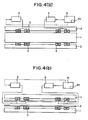
- the rotational device that realizes the method for the present invention that comprises an outer stator 2 and an inner rotor 1 or (see Fig 4(b) ) an outer rotor land an inner stator 2.
- a rotational bearing 3 lies between the rotor 1 and the stator 2.
- Either or both of the lubricant supply time at predetermined time intervals and/or the amount of lubricant supplied at one time are determined in accordance with the speed of the rotational bearing 3.
- a command concerning an appropriate time interval stored in a memory 51 and the measurement of the amount of lubricant supplied at one time is transmitted to the lubricant supply device 4 by means of a computer 5.
- the only way to determine the appropriate time interval and the appropriate supply quantity at one time for lubricating each rotational bearing 3 in accordance with a predetermined angular velocity is to perform trial-and-error experiments.
- the appropriate time interval and the appropriate supply quantity cannot be calculated at one try by a specific theory.
- the appropriate time interval and amount of lubricant required fall within a certain range, and they are not limited to specific values.
- the upper limit of the lubricant supply quantity at one time is based on whether the temperature rises sharply or not immediately after the lubricant is supplied, and this upper limit is confirmed beforehand by an experiment.
- the time interval and quantity of lubricant supplied at one time is not limited to the aforementioned maximum time interval and the upper limit of the supply quantity.
- a supply quantity at one time that corresponds to the standardized time interval can be calculated according to the formula: (standardized time interval) + (maximum time interval) ⁇ (upper limit of the aforementioned supply quantity at one time), the reason being that there is a roughly proportional relationship between time interval and amount of lubricant required.
- the amount of lubricant required obtained by the above calculation corresponds to a minimum value of the amount of lubricant required under the condition of the desired time interval as a result of dividing by the maximum time interval.
- the rotational bearing 3 will be gradually filled with the lubricant, and the temperature of the rotational bearing 3 will gradually rise when the lubricant present becomes too large.
- the lubricant supply quantity present just before a rise in temperature corresponds to a maximum value of an appropriate supply quantity under the standardized time interval.
- a time interval shorter than the maximum time interval is set as a standard, a minimum value obtained according to the above formula, a maximum value confirmed by the above experiment, and an intermediate value between the two correspond to the appropriate lubricant supply quantity at one time, can be set.
- Figure 1 shows the structure of a preferred lubricating device. It comprises a ratchet 42, rotated by an air cylinder 41 that moves a ratchet pawl 46. A screw-threaded piston 43 is disposed at an end of a screw 47 that is slightly moved by the screw 47 that is disposed at the centre of the ratchet 42. As a result, a small quantity of the lubricant is emitted, and thereby the lubricant can be supplied at predetermined time intervals.
- a gear rotated by a pulse motor can replace the ratchet 42.
- a flow rate control valve 44 is disposed in an operating circuit of the air cylinder 41 as shown in Fig. 1 , the supply of the lubricant can be brought into a sluggish state.
- a sluggish supply is effective especially when a highly viscous lubricant, such as grease, is used.
- the computer 5 calculates an appropriate time interval and an appropriate amount of lubricant with respect to the arbitrary revolving speed of each individual rotational bearing 3 in order to automate the lubricant supply method.
- This calculation is performed as follows.
- An appropriate time interval and amount of lubricant are preset with respect to a plurality of angular velocities.
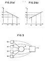
- the rotational bearing 3 selects preset angular velocities on both sides that are nearest to the angular velocity according to the input signal, i.e., a maximum value ⁇ 1 of angular velocities smaller than the angular velocity according to the input signal and a minimum value ⁇ 2 of angular velocities greater than the angular velocity according to the input signal, from among the plurality of stored angular velocities as shown in the graph of Fig. 2 .
- T 0 T 1 ⁇ ⁇ 2 - ⁇ 0 + T 2 ⁇ ⁇ 0 - ⁇ 1 / ⁇ 2 - ⁇ 1
- V 0 V 1 ⁇ ⁇ 2 - ⁇ 0 + V 2 ⁇ ⁇ 0 - ⁇ 1 / ⁇ 2 - ⁇ 1
- T 1 is an appropriate time interval corresponding to the angular velocity ⁇ 1
- V 1 is the amount of lubricant required
- T 2 is an appropriate time interval corresponding to the angular velocity ⁇ 2
- V 2 is the amount of lubricant required.
- a single computer 5 is used for a plurality of rotational devices and a plurality of corresponding rotational bearings 3, thus improving the set up discussed in the second example that employs a system in which time interval and amount of lubricant required are determined according to calculations, and in which the computers 5 are assigned to the plurality of rotational bearings 3, respectively.
- the computer 5 of example 2 cannot receive angular velocity signals from each of a plurality of rotational bearings and perform calculations simultaneously.
- the single computer 5 is connected to the plurality of rotational bearings 3 through a discrimination circuit 6.
- Each rotational bearing 3 transmits a angular velocity signal and a discrimination signal to the discrimination circuit 6.
- the discrimination circuit 6 has a circuit component that determines the order in which the respective signals have been input.
- a step of temporarily storing the signals in the memory 51 in the order of reception is executed.
- the signals are transmitted to the computer 5 without executing this signal-storing step. If some or all of the signals are received at the same time, the angular velocity signals and the discrimination signals that are received at the same time are stored in the memory 51, and the order of the input signals from each of the rotational bearings 3 that are received at the same time is determined according to the order predetermined by a program, and the signals received at the same time are transmitted to the computer 5 in the determined order.
- the computer 5 can perform calculation of an appropriate time interval and an appropriate amount of lubricant, and can transmit output signals resulting from the calculation to each rotational bearing 3 on the basis of the discrimination signals sent from rotational bearings vis the discrimination circuit 6.
- the angular velocity signals and the discrimination signals are sequentially input from the discrimination circuit 6 to the computer 5 according to a predetermined order, and a given calculation is performed even if the angular velocity signals are input from the rotational bearings 3 at the same time. Therefore, serious obstacles do not arise in controlling an appropriate time interval and amount of lubricant required.
- the lubricant can be supplied rationally and appropriately and thus accidents due to wear of a rotational bearing can be prevented and the rotational bearing can be safely operated for a long time.
- the present invention can be suitably applied to the lubricant supply, and appropriate processing can be applied to a highly viscous lubricant such as grease.
- automatic control can be carried out for an appropriate time interval and an appropriate supply quantity with respect to various angular velocities.
- a single computer can operate a plurality of rotational bearings extremely economically.
Priority Applications (1)
| Application Number | Priority Date | Filing Date | Title |
|---|---|---|---|
| DE60218577T DE60218577T3 (de) | 2001-07-27 | 2002-05-28 | Schmierungsverfahren für Umdrehungsvorrichtung |
Applications Claiming Priority (2)
| Application Number | Priority Date | Filing Date | Title |
|---|---|---|---|
| JP2001227128A JP2003042392A (ja) | 2001-07-27 | 2001-07-27 | 回転部支持体における潤滑油供給方法 |
| JP2001227128 | 2001-07-27 |
Publications (3)
| Publication Number | Publication Date |
|---|---|
| EP1279848A1 EP1279848A1 (en) | 2003-01-29 |
| EP1279848B1 EP1279848B1 (en) | 2007-03-07 |
| EP1279848B2 true EP1279848B2 (en) | 2011-11-16 |
Family
ID=19059834
Family Applications (1)
| Application Number | Title | Priority Date | Filing Date |
|---|---|---|---|
| EP02100570A Expired - Fee Related EP1279848B2 (en) | 2001-07-27 | 2002-05-28 | Method for Lubricating a Rotational Device |
Country Status (5)
| Country | Link |
|---|---|
| US (1) | US6705431B2 (ja) |
| EP (1) | EP1279848B2 (ja) |
| JP (1) | JP2003042392A (ja) |
| CA (1) | CA2366173C (ja) |
| DE (1) | DE60218577T3 (ja) |
Families Citing this family (11)
| Publication number | Priority date | Publication date | Assignee | Title |
|---|---|---|---|---|
| WO2003074889A1 (fr) * | 2002-03-05 | 2003-09-12 | Ntn Corporation | Procede et dispositif de lubrification de roulement |
| JP4683870B2 (ja) * | 2004-07-14 | 2011-05-18 | アイ・エム・エヌ株式会社 | 回転部支持体における潤滑油供給方法 |
| JP2007113780A (ja) * | 2005-09-21 | 2007-05-10 | Komori Corp | 回転体の給油装置 |
| DE102005057610A1 (de) † | 2005-12-02 | 2007-06-06 | Repower Systems Ag | Windenergieanlage mit einer Nachschmiereinrichtung für Generatorlager |
| ATE504391T1 (de) * | 2007-11-08 | 2011-04-15 | Step Tec Ag | Wellenkühlung für eine werkzeug-motorspindel |
| WO2011047285A1 (en) * | 2009-10-16 | 2011-04-21 | University Of Virginia Patent Foundation | Gas-expanded lubricants for increased energy efficiency and related method and system |
| US8910751B2 (en) * | 2010-06-08 | 2014-12-16 | Flanders Electric Motor Service, Inc. | Bearing lubrication system |
| WO2014094801A1 (en) * | 2012-12-20 | 2014-06-26 | Aktiebolaget Skf | Machine arrangement |
| CN109185682B (zh) * | 2018-09-28 | 2020-05-05 | 张国祥 | 一种自带黄油机 |
| CN112934616B (zh) * | 2021-01-28 | 2022-03-29 | 深圳市磐锋精密技术有限公司 | 一种高效节能的自动涂润滑油治具及其使用方法 |
| CN113948267B (zh) * | 2021-11-25 | 2022-07-01 | 重庆大学 | 一种应用于脉冲放电连接的高强度线圈支撑平台 |
Citations (6)
| Publication number | Priority date | Publication date | Assignee | Title |
|---|---|---|---|---|
| US4738336A (en) † | 1987-04-27 | 1988-04-19 | Honeywell, Inc. | Controlled replenishing lubrication system |
| US4836334A (en) † | 1986-06-25 | 1989-06-06 | Skf Industrial Trading And Development Co., B.V. | Lubricating device |
| EP0374958A2 (en) † | 1988-12-23 | 1990-06-27 | Hitachi, Ltd. | Apparatus for supplying lubricant |
| EP0639696A1 (en) † | 1993-04-02 | 1995-02-22 | Yamaha Hatsudoki Kabushiki Kaisha | Method and system for lubricating an intermal combustion engine |
| US5971107A (en) † | 1993-03-18 | 1999-10-26 | Barmag Ag | System for supplying lubricant to a plurality of bearings |
| EP1277977A1 (en) † | 2001-07-19 | 2003-01-22 | IMN Co., Ltd | Rotational device |
Family Cites Families (11)
| Publication number | Priority date | Publication date | Assignee | Title |
|---|---|---|---|---|
| US4324316A (en) * | 1980-01-28 | 1982-04-13 | Master Pneumatic-Detroit, Inc. | Injection lubricator controlled by counting mechanism |
| US4527661A (en) * | 1981-10-29 | 1985-07-09 | Kearney & Trecker Corporation | Adaptive control system for machine tool or the like |
| US4520902A (en) * | 1983-04-19 | 1985-06-04 | Lubriquip-Houdaille, Inc. | Lubricant applying system and injector means |
| FR2647182B1 (fr) * | 1989-05-22 | 1992-01-10 | Cit Alcatel | Dispositif pour l'alimentation en graisse de plusieurs paliers |
| EP0458499B1 (en) * | 1990-05-21 | 1997-07-23 | Makino Milling Machine Co. Ltd. | Apparatus for cooling a spindle bearing of a machine |
| DE4104793A1 (de) * | 1991-02-16 | 1992-08-20 | Memminger Iro Gmbh | Schmiereinrichtung zur versorgung mehrerer schmierstellen, insbesondere einer strickmaschine, mit schmiermittel, vorzugsweise oel |
| US5381874A (en) * | 1993-10-15 | 1995-01-17 | Caterpillar Inc. | Automatic lubrication control |
| US5878842A (en) * | 1997-03-19 | 1999-03-09 | Trico Manufacturing Corporation | Volumetric lubricant dispensing apparatus and method of use for same |
| DE19959472A1 (de) * | 1999-12-10 | 2001-06-21 | Sundwig Gmbh | Wälzlagerung für eine Welle oder Rolle und Verfahren zur Schmierung einer solchen Wälzlagerung |
| JP2001208085A (ja) * | 2000-01-26 | 2001-08-03 | Nsk Ltd | 転がり軸受装置用潤滑装置 |
| EP1510749A3 (en) * | 2000-10-13 | 2010-03-10 | Nsk Ltd | Spindle apparatus |
-
2001
- 2001-07-27 JP JP2001227128A patent/JP2003042392A/ja active Pending
- 2001-12-20 US US10/028,591 patent/US6705431B2/en not_active Expired - Lifetime
- 2001-12-27 CA CA002366173A patent/CA2366173C/en not_active Expired - Lifetime
-
2002
- 2002-05-28 EP EP02100570A patent/EP1279848B2/en not_active Expired - Fee Related
- 2002-05-28 DE DE60218577T patent/DE60218577T3/de not_active Expired - Lifetime
Patent Citations (6)
| Publication number | Priority date | Publication date | Assignee | Title |
|---|---|---|---|---|
| US4836334A (en) † | 1986-06-25 | 1989-06-06 | Skf Industrial Trading And Development Co., B.V. | Lubricating device |
| US4738336A (en) † | 1987-04-27 | 1988-04-19 | Honeywell, Inc. | Controlled replenishing lubrication system |
| EP0374958A2 (en) † | 1988-12-23 | 1990-06-27 | Hitachi, Ltd. | Apparatus for supplying lubricant |
| US5971107A (en) † | 1993-03-18 | 1999-10-26 | Barmag Ag | System for supplying lubricant to a plurality of bearings |
| EP0639696A1 (en) † | 1993-04-02 | 1995-02-22 | Yamaha Hatsudoki Kabushiki Kaisha | Method and system for lubricating an intermal combustion engine |
| EP1277977A1 (en) † | 2001-07-19 | 2003-01-22 | IMN Co., Ltd | Rotational device |
Non-Patent Citations (1)
| Title |
|---|
| BRONSTEIN K.A SEMENDJAJEW, TASCHENBUCH DER MATHEMATIK, no. 25, - 1 January 1991 (1991-01-01), VERLAG HARRI DEUTSCH STUTTGART, pages 218 - 219 † |
Also Published As
| Publication number | Publication date |
|---|---|
| DE60218577T2 (de) | 2007-11-29 |
| DE60218577T3 (de) | 2012-05-10 |
| US20030019691A1 (en) | 2003-01-30 |
| US6705431B2 (en) | 2004-03-16 |
| EP1279848A1 (en) | 2003-01-29 |
| CA2366173A1 (en) | 2003-01-27 |
| CA2366173C (en) | 2006-01-03 |
| EP1279848B1 (en) | 2007-03-07 |
| JP2003042392A (ja) | 2003-02-13 |
| DE60218577D1 (de) | 2007-04-19 |
Similar Documents
| Publication | Publication Date | Title |
|---|---|---|
| EP1279848B2 (en) | Method for Lubricating a Rotational Device | |
| CN104181851B (zh) | 一种自动变速器自动测试方法及系统 | |
| US7791307B2 (en) | AC motor controller | |
| EP1747446A1 (en) | Method of monitoring gas turbine engine operation | |
| US10309304B2 (en) | Electrical augmentation of a gas turbine engine | |
| ES2145331T3 (es) | Procedimiento para la lubricacion dosificada de una transmision de cadena. | |
| CN102401225A (zh) | 线性传动装置润滑监控系统 | |
| US7826912B2 (en) | Method and assembly for determining and/or producing a drive or parts for a drive and interface and method for determining an operational reliability factor SB | |
| FR3125785B1 (fr) | Procédé de pilotage de véhicule et d’évitement d’obstacle | |
| EP3710897B1 (de) | Verfahren und vorrichtung zum cyberangriffsschutz von pumpenaggregaten | |
| JP4683871B2 (ja) | 回転部支持体における潤滑油供給方法 | |
| JP4683870B2 (ja) | 回転部支持体における潤滑油供給方法 | |
| JPH11351361A (ja) | 歯車装置の潤滑装置および潤滑方法 | |
| EP3191263B1 (en) | A robot controller, a robot unit and a method for controlling the operation of a robot unit | |
| KR101745163B1 (ko) | 힌지 이동식 오일공급장치 및 이의 제어방법 | |
| US20200386228A1 (en) | Steam compressor comprising a dry positive-displacement unit as a spindle compressor | |
| CN112269348A (zh) | 一种运动控制急停方法 | |
| Merttopçuoğlu et al. | SDRE control of the control actuation system of a guided missile | |
| EP3958458A1 (en) | Software based condition monitoring for machines | |
| HIGO et al. | Dynamic characteristic and power consumption on an electro-pneumatic hybrid positioning system | |
| EP2435712B1 (en) | Controlled hydraulic systems comprising a variable drive ratio device | |
| CN116857080A (zh) | 一种直升机发动机控制方法、装置、设备及存储介质 | |
| WO2016034723A1 (de) | Druckluftsystem mit modifizerbarer förderrate | |
| Zelić et al. | Determination of the Braking Period Duration in Case of an Electric Motor Driving Mechanism with a Hydrodynamic Coupling | |
| EP1130763B1 (de) | Einrichtung zur Erfassung des Drehmoments eines Generators eines Kraftfahrzeugs |
Legal Events
| Date | Code | Title | Description |
|---|---|---|---|
| PUAI | Public reference made under article 153(3) epc to a published international application that has entered the european phase |
Free format text: ORIGINAL CODE: 0009012 |
|
| AK | Designated contracting states |
Designated state(s): AT BE CH CY DE DK ES FI FR GB GR IE IT LI LU MC NL PT SE TR |
|
| AX | Request for extension of the european patent |
Extension state: AL LT LV MK RO SI |
|
| 17P | Request for examination filed |
Effective date: 20030711 |
|
| AKX | Designation fees paid |
Designated state(s): DE FR GB IT |
|
| GRAP | Despatch of communication of intention to grant a patent |
Free format text: ORIGINAL CODE: EPIDOSNIGR1 |
|
| GRAS | Grant fee paid |
Free format text: ORIGINAL CODE: EPIDOSNIGR3 |
|
| GRAA | (expected) grant |
Free format text: ORIGINAL CODE: 0009210 |
|
| AK | Designated contracting states |
Kind code of ref document: B1 Designated state(s): DE FR GB IT |
|
| REG | Reference to a national code |
Ref country code: GB Ref legal event code: FG4D |
|
| REF | Corresponds to: |
Ref document number: 60218577 Country of ref document: DE Date of ref document: 20070419 Kind code of ref document: P |
|
| ET | Fr: translation filed | ||
| PLBI | Opposition filed |
Free format text: ORIGINAL CODE: 0009260 |
|
| PLAX | Notice of opposition and request to file observation + time limit sent |
Free format text: ORIGINAL CODE: EPIDOSNOBS2 |
|
| 26 | Opposition filed |
Opponent name: KIENINGER TECHNOLOGIE GMBH Effective date: 20071206 |
|
| PLBB | Reply of patent proprietor to notice(s) of opposition received |
Free format text: ORIGINAL CODE: EPIDOSNOBS3 |
|
| PLAB | Opposition data, opponent's data or that of the opponent's representative modified |
Free format text: ORIGINAL CODE: 0009299OPPO |
|
| APAH | Appeal reference modified |
Free format text: ORIGINAL CODE: EPIDOSCREFNO |
|
| APBM | Appeal reference recorded |
Free format text: ORIGINAL CODE: EPIDOSNREFNO |
|
| APBP | Date of receipt of notice of appeal recorded |
Free format text: ORIGINAL CODE: EPIDOSNNOA2O |
|
| APBU | Appeal procedure closed |
Free format text: ORIGINAL CODE: EPIDOSNNOA9O |
|
| PUAH | Patent maintained in amended form |
Free format text: ORIGINAL CODE: 0009272 |
|
| STAA | Information on the status of an ep patent application or granted ep patent |
Free format text: STATUS: PATENT MAINTAINED AS AMENDED |
|
| 27A | Patent maintained in amended form |
Effective date: 20111116 |
|
| AK | Designated contracting states |
Kind code of ref document: B2 Designated state(s): DE FR GB IT |
|
| REG | Reference to a national code |
Ref country code: DE Ref legal event code: R102 Ref document number: 60218577 Country of ref document: DE |
|
| REG | Reference to a national code |
Ref country code: DE Ref legal event code: R102 Ref document number: 60218577 Country of ref document: DE Effective date: 20111116 |
|
| REG | Reference to a national code |
Ref country code: FR Ref legal event code: PLFP Year of fee payment: 14 |
|
| PGFP | Annual fee paid to national office [announced via postgrant information from national office to epo] |
Ref country code: DE Payment date: 20150519 Year of fee payment: 14 Ref country code: GB Payment date: 20150527 Year of fee payment: 14 |
|
| PGFP | Annual fee paid to national office [announced via postgrant information from national office to epo] |
Ref country code: FR Payment date: 20150508 Year of fee payment: 14 Ref country code: IT Payment date: 20150515 Year of fee payment: 14 |
|
| REG | Reference to a national code |
Ref country code: DE Ref legal event code: R119 Ref document number: 60218577 Country of ref document: DE |
|
| GBPC | Gb: european patent ceased through non-payment of renewal fee |
Effective date: 20160528 |
|
| PG25 | Lapsed in a contracting state [announced via postgrant information from national office to epo] |
Ref country code: IT Free format text: LAPSE BECAUSE OF NON-PAYMENT OF DUE FEES Effective date: 20160528 |
|
| REG | Reference to a national code |
Ref country code: FR Ref legal event code: ST Effective date: 20170131 |
|
| PG25 | Lapsed in a contracting state [announced via postgrant information from national office to epo] |
Ref country code: FR Free format text: LAPSE BECAUSE OF NON-PAYMENT OF DUE FEES Effective date: 20160531 Ref country code: DE Free format text: LAPSE BECAUSE OF NON-PAYMENT OF DUE FEES Effective date: 20161201 |
|
| PG25 | Lapsed in a contracting state [announced via postgrant information from national office to epo] |
Ref country code: GB Free format text: LAPSE BECAUSE OF NON-PAYMENT OF DUE FEES Effective date: 20160528 |