EP1277789A2 - Vorrichtung und Verfahren zur Aufbereitung von Metall enthaltenden organischen Abfallstoffen - Google Patents
Vorrichtung und Verfahren zur Aufbereitung von Metall enthaltenden organischen Abfallstoffen Download PDFInfo
- Publication number
- EP1277789A2 EP1277789A2 EP02090241A EP02090241A EP1277789A2 EP 1277789 A2 EP1277789 A2 EP 1277789A2 EP 02090241 A EP02090241 A EP 02090241A EP 02090241 A EP02090241 A EP 02090241A EP 1277789 A2 EP1277789 A2 EP 1277789A2
- Authority
- EP
- European Patent Office
- Prior art keywords
- magnetic
- depolymerization
- bath
- discharge material
- components
- Prior art date
- Legal status (The legal status is an assumption and is not a legal conclusion. Google has not performed a legal analysis and makes no representation as to the accuracy of the status listed.)
- Withdrawn
Links
- 239000000463 material Substances 0.000 title claims abstract description 89
- 229910052751 metal Inorganic materials 0.000 title claims abstract description 14
- 239000002184 metal Substances 0.000 title claims abstract description 14
- 238000000034 method Methods 0.000 title claims abstract description 14
- 239000010815 organic waste Substances 0.000 title claims abstract description 10
- 230000005291 magnetic effect Effects 0.000 claims abstract description 117
- 230000008021 deposition Effects 0.000 claims abstract description 16
- 239000002699 waste material Substances 0.000 claims abstract description 13
- 239000002245 particle Substances 0.000 claims description 18
- 238000000926 separation method Methods 0.000 claims description 18
- 238000002360 preparation method Methods 0.000 claims description 3
- 238000000151 deposition Methods 0.000 claims 5
- 239000007787 solid Substances 0.000 description 14
- 239000007795 chemical reaction product Substances 0.000 description 9
- 239000004071 soot Substances 0.000 description 6
- 229910000831 Steel Inorganic materials 0.000 description 5
- 230000002787 reinforcement Effects 0.000 description 5
- 239000010959 steel Substances 0.000 description 5
- 230000032258 transport Effects 0.000 description 5
- 230000005484 gravity Effects 0.000 description 4
- 238000013461 design Methods 0.000 description 3
- 230000005415 magnetization Effects 0.000 description 2
- 238000002844 melting Methods 0.000 description 2
- 230000008018 melting Effects 0.000 description 2
- 238000012545 processing Methods 0.000 description 2
- 238000012546 transfer Methods 0.000 description 2
- 238000009825 accumulation Methods 0.000 description 1
- 230000001464 adherent effect Effects 0.000 description 1
- 230000000903 blocking effect Effects 0.000 description 1
- 239000000470 constituent Substances 0.000 description 1
- 238000001816 cooling Methods 0.000 description 1
- 238000011161 development Methods 0.000 description 1
- 230000018109 developmental process Effects 0.000 description 1
- 238000006073 displacement reaction Methods 0.000 description 1
- 230000002349 favourable effect Effects 0.000 description 1
- 125000000524 functional group Chemical group 0.000 description 1
- 238000010438 heat treatment Methods 0.000 description 1
- 239000004615 ingredient Substances 0.000 description 1
- 239000000155 melt Substances 0.000 description 1
- 229910001092 metal group alloy Inorganic materials 0.000 description 1
- 150000002739 metals Chemical class 0.000 description 1
- 239000000047 product Substances 0.000 description 1
- 238000004064 recycling Methods 0.000 description 1
- 150000003839 salts Chemical class 0.000 description 1
- 239000000126 substance Substances 0.000 description 1
- 230000001360 synchronised effect Effects 0.000 description 1
Images

Classifications
-
- C—CHEMISTRY; METALLURGY
- C22—METALLURGY; FERROUS OR NON-FERROUS ALLOYS; TREATMENT OF ALLOYS OR NON-FERROUS METALS
- C22B—PRODUCTION AND REFINING OF METALS; PRETREATMENT OF RAW MATERIALS
- C22B7/00—Working up raw materials other than ores, e.g. scrap, to produce non-ferrous metals and compounds thereof; Methods of a general interest or applied to the winning of more than two metals
- C22B7/001—Dry processes
-
- C—CHEMISTRY; METALLURGY
- C10—PETROLEUM, GAS OR COKE INDUSTRIES; TECHNICAL GASES CONTAINING CARBON MONOXIDE; FUELS; LUBRICANTS; PEAT
- C10G—CRACKING HYDROCARBON OILS; PRODUCTION OF LIQUID HYDROCARBON MIXTURES, e.g. BY DESTRUCTIVE HYDROGENATION, OLIGOMERISATION, POLYMERISATION; RECOVERY OF HYDROCARBON OILS FROM OIL-SHALE, OIL-SAND, OR GASES; REFINING MIXTURES MAINLY CONSISTING OF HYDROCARBONS; REFORMING OF NAPHTHA; MINERAL WAXES
- C10G1/00—Production of liquid hydrocarbon mixtures from oil-shale, oil-sand, or non-melting solid carbonaceous or similar materials, e.g. wood, coal
- C10G1/10—Production of liquid hydrocarbon mixtures from oil-shale, oil-sand, or non-melting solid carbonaceous or similar materials, e.g. wood, coal from rubber or rubber waste
-
- C—CHEMISTRY; METALLURGY
- C22—METALLURGY; FERROUS OR NON-FERROUS ALLOYS; TREATMENT OF ALLOYS OR NON-FERROUS METALS
- C22B—PRODUCTION AND REFINING OF METALS; PRETREATMENT OF RAW MATERIALS
- C22B1/00—Preliminary treatment of ores or scrap
- C22B1/005—Preliminary treatment of scrap
-
- C—CHEMISTRY; METALLURGY
- C22—METALLURGY; FERROUS OR NON-FERROUS ALLOYS; TREATMENT OF ALLOYS OR NON-FERROUS METALS
- C22B—PRODUCTION AND REFINING OF METALS; PRETREATMENT OF RAW MATERIALS
- C22B7/00—Working up raw materials other than ores, e.g. scrap, to produce non-ferrous metals and compounds thereof; Methods of a general interest or applied to the winning of more than two metals
- C22B7/005—Separation by a physical processing technique only, e.g. by mechanical breaking
-
- Y—GENERAL TAGGING OF NEW TECHNOLOGICAL DEVELOPMENTS; GENERAL TAGGING OF CROSS-SECTIONAL TECHNOLOGIES SPANNING OVER SEVERAL SECTIONS OF THE IPC; TECHNICAL SUBJECTS COVERED BY FORMER USPC CROSS-REFERENCE ART COLLECTIONS [XRACs] AND DIGESTS
- Y02—TECHNOLOGIES OR APPLICATIONS FOR MITIGATION OR ADAPTATION AGAINST CLIMATE CHANGE
- Y02P—CLIMATE CHANGE MITIGATION TECHNOLOGIES IN THE PRODUCTION OR PROCESSING OF GOODS
- Y02P10/00—Technologies related to metal processing
- Y02P10/20—Recycling
Definitions
- the present invention relates to a device for processing high temperature resistant components, especially high temperature resistant Metal parts, containing organic waste with one High temperature region comprising a reactor arranged therein Depolymerization bath for thermal depolymerization of the organic Components of the waste materials and with one in the high temperature range of the reactor arranged separation device for separation at least part of the high temperature resistant components from the discharge material stream of the depolymerization bath. It affects a corresponding process for the preparation of such Waste.
- a generic device is for example from US 3,770,419 known.
- the device described there has in a reactor Depolymerization bath made of a molten metal, from the Surface released or created during the depolymerization Solids, such as metal parts contained in the waste materials higher melting temperature or soot, drawn off by rotating disks become.
- the metal parts and the soot are made from the High temperature range of the reactor and led to a later Time separated.
- the known device has the disadvantage that the metal parts only relatively late, namely after removal from the high temperature range of the reactor and after a cooling process separated from the soot become.
- Such metal parts for example those in depolymerization released steel reinforcements from used tires, however, tend to become with each other or with ledges, undercuts, etc. on your Interlocking transport route. Due to the common transport with the soot is subject to relatively strong movements, so that it to partially or even completely block the transport routes can come through hooked and tangled metal parts.
- the present invention is therefore based on the object of a device as well as a method of the type mentioned at the beginning who do not, or at least to a lesser extent, the disadvantages mentioned above Have dimensions and especially with a simple structure Ensure trouble-free operation as possible.
- the present invention solves this problem on the basis of a device according to the preamble of claim 1 by the in the characterizing Part of claim 1 specified features. It solves this task further proceeding from a method according to the preamble of Claim 17 by those specified in the characterizing part of claim 17 Characteristics.
- the invention is based on the technical teaching that one with particular a reliable preparation is achieved by simple means, if the largest possible proportion of the solid components of the waste materials, those for blocking or clogging the discharge routes and facilities tend to early as possible from the other solid reaction products to be discharged is deposited.
- the reactor has a magnetic device, in particular an electromagnetic device, to arrange, which allows magnetic components waste materials, such as the steel reinforcement of used tires, which usually the majority of those used to block or clog the Disposal routes and facilities tend to contain components of the waste materials represent to separate very early from the other solid reaction products.
- This not only enables smoother operation, it does can also the individual discharge devices for the magnetic Components and the other solid reaction products specifically for that each of the goods to be discharged must be designed. Because of the very different Condition of the magnetic components and the other solid The respective discharge device can react products accordingly be made correspondingly simpler, since they are only used for removing goods must be designed with a relatively uniform consistency.
- the use of the magnetic device enables separation of the magnetic components without causing excessive movements of the deposited magnetic components comes, which in turn cannot get caught or tangled with each other.
- the magnetic device can simply be designed so that it is too no jamming of the magnetic components on the magnetic device comes.
- the magnet device can be designed as a permanent magnet. Prefers it is designed as an electromagnetic device, since with this a particularly easy removal of the magnetic components from the Magnetic device is possible.
- the removal of the magnetic components from the electromagnetic device can be done in any way.
- a scraper or the like may be provided from time to time, for example at fixed intervals, the adhering magnetic components stripped from the magnetic device.
- the first preferably comprises Electromagnetic device, however, one for temporarily switching off the Control device designed to be magnetically effective, so that no such wiper is necessary, but the magnetic components already on the ground gravity fall off the magnetic device.
- the deposition device then preferably has one of the first electromagnet devices at least temporarily assigned discharge device to lead away from the first electromagnetic device when the Magnetic effect released magnetic components.
- the discharge device can be any of the electromagnetic device Be spatially assigned. It is preferably below the magnetic one Component-bearing area of the electromagnetic device arranged so that the released by the electromagnetic device magnetic components simply due to gravity on the discharge device to move, in the simplest case falling on this.
- the temporary assignment can then take place, for example, in that the discharge device from time to time among the magnetic components supporting area of the electromagnetic device is moved to pick up the released magnetic components there.
- the discharge device of the electromagnetic device it is possible for the discharge device of the electromagnetic device to be stationary assign, but only temporarily the way for that of the electromagnetic device released magnetic components to the discharge device release.
- the control device for temporarily demagnetizing the first electromagnetic device is trained.
- the electromagnetic device can do this from time to time for example, with corresponding AC sequences become. This ensures that it does not become permanent over time Magnetization of the corresponding parts of the electromagnetic device which would prevent the magnetic components from coming off detach from the electromagnetic device in the desired manner.
- the first electromagnetic device is the magnetic one Includes constituent electromagnetic unit and the discharge device one at least temporarily below the electromagnetic unit arranged first conveyor unit. This first conveyor unit serves to lead away from the first electromagnetic device when the Magnetic effect released magnetic components.
- the temporary spatial allocation between the first conveyor unit and As already mentioned above, the electromagnetic unit can be made that the conveyor unit moves under the electromagnetic unit from time to time, for example, be pivoted to the released there magnetic components.
- the conveyor unit is preferred permanently assigned to the electromagnet unit, but it is only temporarily the path for the magnetic released by the electromagnetic unit Components released for the first conveyor unit.
- the first conveyor unit can be designed in any way. It can be driven be, as is the case with a conveyor belt or the like Case is. However, it preferably uses gravity to remove the magnetic components.
- the first conveyor unit preferably comprises a simple slide or the like.
- the discharge device of the electromagnetic device be assigned permanently, but only temporarily the way for the magnetic components released by the electromagnetic device be released to the discharge facility.
- the deposition device is one of the first electromagnetic device assigned second conveyor unit for passing the discharge material on the first electromagnetic device.
- the second conveyor then at least one of the first electromagnetic devices temporarily assigned passage device. Through this passage device through that can then be released by the electromagnetic device magnetic components reach the discharge device, for example falling.
- control device of the electromagnetic device is connected to the second conveyor unit such that the Switching off the magnetic effect of the electromagnetic device with the assignment the passage device synchronized to the electromagnetic device is.
- the magnetic effect is only switched off if the passage device of the electromagnetic device is such is assigned that the released magnetic components the Passage device can also pass.
- the second conveyor unit can in turn be in any known manner be designed.
- it can be from a conveyor belt or the like be formed, which has one or more corresponding through openings has, through which by the electromagnetic device released magnetic components can fall.
- the second conveyor unit comprises a disk-shaped device an axis rotatable substantially perpendicular to its plane Conveying element with a passage device in the form of a recess.
- the recess passes with each revolution of the conveyor element the electromagnetic device once. Switches at this time the control device then abolishes the magnetic action, so that the released magnetic components through the recess to the first Conveyor unit can get.
- the conveying element in the form of a circular disk with a substantially Circular sector-shaped passage opening is formed.
- drops or particles of the depolymerization bath adhering to the discharge material shaken off by the discharge material overcome a certain drop got to.
- This simple shaking is more adherent to the discharge material Drop or particle is thanks to the arrangement of the separation device possible in the high temperature range of the reactor.
- the separation device does this a second conveyor unit assigned to the first magnet device for Guide the discharge material past the first magnet device and a feed device for feeding the discharge material from Depolymerization bath is provided.
- This feeder is the second Conveyed unit assigned such that a sufficient head for Shake off the discharge material, especially the magnetic one Components, adhering drops or particles of the depolymerization bath given when the components hit the second conveyor unit is.
- the second conveyor unit for removal is carried along with the discharge material Drops or particles of the depolymerization bath are formed.
- the second conveyor unit preferably has a channel-like design Section for removal carried along with the discharge material Drops or particles of the depolymerization bath.
- the separation device is a bath return device for recycling with the discharge material stream assigned droplets or particles of the depolymerization bath, so that the return is particularly easy.
- the bathroom return facility includes because of the particularly simple design preferably a return element designed in the manner of an overflow.
- this is designed for multi-stage deposition of magnetic components.
- the present invention further relates to a separation device for a device according to the invention.
- the separation device points in doing so, the features just outlined so that with respect to them Features and the advantages that can be achieved on the above description is referred.
- the present invention further relates to a method for processing of high temperature resistant components, especially high temperature resistant ones Metal parts, containing organic waste, in which thermal depolymerization in a depolymerization bath of a reactor of the organic components of the waste materials takes place and in the high temperature range of the reactor at least part of the high temperature resistant Materials from the discharge material stream of the depolymerization bath is deposited.
- this takes place at an early stage Deposition of magnetic components in the high temperature range of the reactor by magnetic action of a magnetic device.
- the magnetic effect is preferably temporarily switched off by that when switched off Magnetic effect released by the magnetic device to be able to remove magnetic components.
- the magnetic device can, for example, by a corresponding Drive device past which discharge material is passed.
- the discharge material is preferred due to the simpler implementation for separating the magnetic components on the magnetic device past.
- the droplets or particles are separated in preferred variants of the method according to the invention by shaking off the Discharge material, especially adhering to the magnetic components
- Drops or particles of the depolymerization bath the moving Discharge material in the high temperature area of the reactor to be shaken off at least a large part of the adhering drops or particles is subjected to sufficient delay. This delay is due in The simplest case is achieved by having the discharge material with a falls on an obstacle at a certain height.
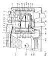
- Figure 1 shows a schematic partial section through an inventive Device 1 for the treatment of organic waste materials, for example of used tires.
- the device 1 comprises a reactor 2 in whose high-temperature region 3 a depolymerization bath 4 is arranged is.
- the depolymerization bath 4 consists of the melt of a heat transfer medium.
- a heat transfer medium In the present example it is a lead melt, it can also melt other heat transfer media, for example use other metals or metal alloys or molten salts.
- the depolymerization bath 4 is used for the thermal depolymerization of the organic waste materials supplied to it via feed means (not shown). In addition to volatile reaction products, this depolymerization produces the - not shown - deduction devices from the Reactor 2 are discharged, also solid reaction products, which the main part of the discharge material 5 of the depolymerization bath 4 form.
- these solid reaction products are to soot produced during thermal depolymerization and to High temperature resistant components of the waste materials that are used in the depolymerization be released from the network.
- these high temperature resistant Components can be reinforcements, for example steel or components made of other materials, their melting point is above the temperature of the bath material.
- the named solids 5 swim due to their compared to that Depolymerization bath 4 of lower density on the surface 6 of the depolymerization bath 4 on and are from this surface 6 via funding 7 with wipers 7.1 in the in the around the dissipated.
- a Feeding means in the form of a slide 8 pass through the solids an opening 9 then into a separator in the form of a separator 10, which is arranged in the high temperature region 3 of the reactor 2.
- the separator 10 comprises a first magnetic device with a through a control device 11 actuatable first electromagnet 12, on the the discharge material of the depolymerization bath fed to the separator 10 4 is passed.
- the magnetic effect of the Electromagnets 12 become the magnetic components of the organic Waste materials, such as steel reinforcements from old tires or the like, separated from the remaining solids by as a result the magnetic effect raised by the electromagnet 12 and thus be lifted out of the discharge material, as shown in FIG. 1 is indicated by the elements 5.1.
- the electromagnet 12 is a first conveyor unit in the form of a slide 13 permanently assigned.
- the slide 13 is below the electromagnet 12 arranged and serves as part of a discharge device for removal the magnetic components 5.1, as soon as these from the electromagnet 12 are released and due to gravity on the slide 13 fall.
- the magnetic components are released by that the control device 11 the magnetic effect of the electromagnet 12th off.
- the discharge material 5 is guided past the electromagnet 12 is carried out by a second conveyor unit 14 with a circular disc Conveying element 15, which is driven by a drive 16 Wave 17 is sitting.
- the axis 17.1 of the shaft 17 runs perpendicular to the Level of the conveyor element 15.
- the discharge material 5 initially falls through the opening 9 on the conveyor element 15 and is then due to Rotation of the conveyor element 15 about the axis 17.1 on the electromagnet 12 passed.
- FIG. 2 which is a perspective view shows part of the device of Figure 1, has the conveying element 15 of the second conveyor unit 14 has a quarter-circular recess 15.1 on.
- This recess 15.1 due to the rotation of the conveyor element 15 located below the electromagnet 12 is the way for those adhering to the electromagnet 12 due to the magnetic action magnetic components 5.1 released to slide 13.
- the control device 11 switches the magnetic effect of the magnet in this constellation 12, so that the magnetic components 5.1 are released and through the recess 15.1 forming a passage device fall on the slide 13.
- the control device 11 not only controls the electromagnet 12, but also the drive 16 and the corresponding connections Funding 7, so that a simple synchronization between them Functional groups of the device is possible.
- the synchronization takes place doing so from two points of view. Firstly, there is no supply of discharge material 5 to the separator 10 when the recess 15.1 is below the opening 9 is arranged so that it is ensured that the separator 10 supplied discharge material 5 also on the electromagnet 12 is led past.
- the electromagnet is switched off 12 as described above is when the recess 15.1 below of the electromagnet 12 is arranged so that it is ensured that the magnetic components 5.1 reliably from the rest of the discharge material be separated.
- Control devices for drives and electromagnets may be provided can, which must then be connected to each other for synchronization.
- control device 11 To prevent permanent magnetization over time of components of the electromagnet 12 or adjacent components of the separator 10, the control device 11 is designed such that it demagnetizes the electromagnet 12 from time to time. For this it applies corresponding AC sequences to the electromagnet 12. This ensures that that of the electromagnet 12 attracted magnetic components 5.1 actually at Switching off the magnetic effect can be released.
- the slide 13 is arranged so that the magnetic striking it Components 5.1 in a arranged under the end of the slide 13 first lock 18 of the separator 10 fall, through which they are discharged become.
- This scraper 19 causes the remaining discharge material as a result the rotation of the conveying element 15 in the direction of that shown in FIG Arrow 20 to the next level of the multi-stage conveyor unit 14 falls.
- This next level is of a second circular disk shape Conveying element 21 with a quarter-circular recess 21.1, which is below the first conveyor element 15 is also arranged on the shaft 17.
- the recess 21.1 of the second conveying element 21 is opposite to the Recess 15.1 of the first conveying element 15 in the circumferential direction in this way offset that it is ensured that that of the first conveyor element 15 discharge material falling on the second conveying element 21 lands and does not fall directly through the recess 21.1. in the shown example, this is ensured by a rotation of 120 °.
- the discharge material is passed through from this second conveying element 21 a second scraper 22 due to the rotation of the conveying element 21 in Direction of the arrow 20 shown in Figure 2 to a further level Conveyed unit 14 transported.
- This next level is from a third circular disk-shaped conveying element 23 with a quarter circle Recess 23.1 formed below the second conveyor element 21 is also arranged on the shaft 17.
- the recess 23.1 of the third conveying element 23 is opposite the Recess 21.1 of the second conveyor element 21 in the circumferential direction offset in such a way that it is ensured that the second conveyor element 21 falling discharge material on the third conveyor element 23 lands and does not fall directly through the recess 23.1. In the example shown, this is guaranteed by a rotation of 120 °. However, it is understood that in other variants of the invention as well other angles of rotation can be selected.
- the discharge material falling from the first conveying element 15 onto the second conveying element 21 and from the second conveying element 21 on the third conveying element 23 cause magnetic components 5.1, when passing the first electromagnet 12 due to any obstacles are not lifted out of the rest of the discharge material have been released from these obstacles or these obstacles be eliminated.
- a second electromagnet 24 is arranged, which is also from the Control device 11 is controlled.
- the third conveyor element 23 leads the discharge material 5 past the second electromagnet 24 so that the largest possible proportion of those just mentioned in the discharge material remaining magnetic components 5.1 due to the magnetic effect of the second electromagnet 24 from the discharge material is lifted out.
- a third scraper 25 assigned to the third conveying element 23 provides for that after the deposition of the magnetic components discharge material still remaining falls into a second lock 26 which it is discharged from the separator 10.
- the separator 10 enables magnetic components of the waste materials, such as the steel reinforcement of old tires, which usually the majority of those used to block or block the discharge routes and - furnishing-prone components of the waste materials very early to separate from the other solid reaction products.
- This is not only a smoother operation possible, but it can also individual discharge devices, in particular the locks 18 and 26, for the magnetic components 5.1 and the other solid reaction products specifically designed for the goods to be discharged. Because of the very different nature of the magnetic components and the other solid reaction products can the respective discharge device accordingly be designed accordingly simpler, since they are only for Removal of goods with a relatively uniform consistency got to.
- the electromagnetic devices 12 and 24 In contrast to the separation by vibrating sieve devices or the like enables the use of the electromagnetic devices 12 and 24 a deposition of the magnetic components 5.1 without it strong movements of the separated magnetic components 5.1 comes, which in turn does not get caught with each other or can tangle up.
- the electromagnetic devices 12 or 24 simply designed so that there is no jamming of the magnetic components 5.1 on the relevant electromagnetic device 12 or 24 is coming.
- the conveying elements have 15, 21 and 23 each have a course inclined to the axis 17 and one circumferential edge web 27, whereby a gutter-like at its edge trained section 28 results. Due to the inclination of the conveyor elements collect in this gutter-like section 28 - under Displacement of substances of lower density - with the discharge material 5 depolymerization bath material discharged from the depolymerization bath 4.
- This depolymerization bath material runs at the ends of the channel-like Section 28 in the region of the recess 15.1 of the first conveyor element 15 on the underlying second conveying element 21. There it collects itself in its groove-like section 28 and runs at the ends this channel-like section 28 in the region of the recess 21.1 of the second conveying element 21 on the third conveying element located below 23. There it collects again in its gutter-like section 28 and finally runs at the ends of this channel-like section 28 in Area of the recess 23.1 of the third conveying element 21 into one below it lying annular groove 29 with a drain 29.1.
- the depolymerization bath material enters the drain via this drain 29.1 Inlet 30.1 of a bath return device 30 with a return element in the form of an overflow 30.2, a collection container 30.3 and a pump device 30.4 for returning the bath material from Collection container 30.3 in the depolymerization bath 4.
- heating elements 31 are provided, which the separator 10 on a sufficient Maintain temperature.
- the overflow 30.2 is arranged so that the surface of the bath material in the area of the inlet 30.1 with the bottom of the separator 10. This ensures that what arrives in this area Discharge material does not get into the bath return device 30, but instead due to the lower density remains in the separator 10 and from time to time by an appropriate facility (not shown), for example a scraper or the like, in the second lock 26 can be promoted.
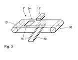
- Figure 3 shows a schematic perspective view of part of a preferred variant of the device 1 'according to the invention, which is in its basic function does not depend on the variant from FIGS. 1 and 2 differs, so that only the differences are dealt with here shall be.
- the second conveyor unit is one Conveyor belt 15 'is formed, which is below the first electromagnet 12 'is arranged.
- the conveyor belt 15 ' transports the discharge material in the direction of arrow 34 past the electromagnet 12 ', then in the manner described above, the magnetic components of the Electromagnet 12 'attracted and thereby from the discharge material be lifted out.
- the control device also controls the drive of the conveyor belt 15 ', so that a corresponding synchronization is possible.
Landscapes
- Chemical & Material Sciences (AREA)
- Engineering & Computer Science (AREA)
- Organic Chemistry (AREA)
- Life Sciences & Earth Sciences (AREA)
- Mechanical Engineering (AREA)
- Manufacturing & Machinery (AREA)
- Geology (AREA)
- Materials Engineering (AREA)
- General Life Sciences & Earth Sciences (AREA)
- Metallurgy (AREA)
- Environmental & Geological Engineering (AREA)
- Oil, Petroleum & Natural Gas (AREA)
- Geochemistry & Mineralogy (AREA)
- Wood Science & Technology (AREA)
- Chemical Kinetics & Catalysis (AREA)
- General Chemical & Material Sciences (AREA)
- Processing Of Solid Wastes (AREA)
Abstract
Description
- Figur 1
- einen schematischen Teilschnitt durch ein bevorzugtes Ausführungsbeispiel der erfindungsgemäßen Vorrichtung;
- Figur 2
- eine schematische perspektivische Ansicht eines Teils der Vorrichtung aus Figur 1;
- Figur 3
- eine schematische perspektivische Ansicht eines weiteren bevorzugten Ausführungsbeispiels der erfindungsgemäßen Vorrichtung.
Claims (21)
- Vorrichtung zur Aufbereitung von hochtemperaturbeständige Bestandteile (5.1), insbesondere hochtemperaturbeständige Metallteile, enthaltenden organischen Abfallstoffen mit einem einen Hochtemperaturbereich (3) umfassenden Reaktor (2), einem darin angeordneten Depolymerisationsbad (4) zur thermischen Depolymerisation der organischen Bestandteile der Abfallstoffe und mit einer im Hochtemperaturbereich (3) des Reaktors (2) angeordneten Abscheidungseinrichtung (10) zur Abscheidung wenigstens eines Teils der hochtemperaturbeständigen Bestandteile (5.1) aus dem Austragsmaterialstrom (5) des Depolymerisationsbades (4), dadurch gekennzeichnet, dass die Abscheidungseinrichtung (10) eine erste Magneteinrichtung (11, 12; 12') zur Abscheidung magnetischer Bestandteile (5.1) umfasst.
- Vorrichtung nach Anspruch 1, dadurch gekennzeichnet, dass die erste Magneteinrichtung als Elektromagneteinrichtung (11, 12; 12') ausgebildet ist.
- Vorrichtung nach Anspruch 2, dadurch gekennzeichnet, dass die erste Elektromagneteinrichtung (11, 12; 12') eine zum zeitweisen Abschalten der Magnetwirkung ausgebildete Steuereinrichtung (11) umfasst und die Abscheidungseinrichtung (10) eine der ersten Elektromagneteinrichtung (11, 12; 12') zumindest zeitweise zugeordnete Abfuhreinrichtung (13; 13') zum Wegführen der von der ersten Elektromagneteinrichtung (11, 12; 12') bei abgeschalteter Magnetwirkung freigegebenen magnetischen Bestandteile (5.1) aufweist.
- Vorrichtung nach Anspruch 3, dadurch gekennzeichnet, dass die Steuereinrichtung (11) zum zeitweisen Entmagnetisieren der ersten Elektromagneteinrichtung (11, 12; 12') ausgebildet ist.
- Vorrichtung nach einem der Ansprüche 2 bis 4, dadurch gekennzeichnet, dass die erste Elektromagneteinrichtung (11, 12; 12') eine Elektromagneteinheit (12; 12') umfasst und die Abfuhreinrichtung (13; 13') eine zumindest zeitweise unterhalb der Elektromagneteinheit angeordnete erste Fördereinheit (13; 13') zum Wegführen der von der ersten Elektromagneteinrichtung (11, 12; 12') bei abgeschalteter Magnetwirkung freigegebenen magnetischen Bestandteile (5.1) umfasst.
- Vorrichtung nach Anspruch 5, dadurch gekennzeichnet, dass die erste Fördereinheit eine Rutsche (13; 13') umfasst.
- Vorrichtung nach einem der Ansprüche 2 bis 6, dadurch gekennzeichnet, dass die Abscheidungseinrichtung (10) eine der ersten Elektromagneteinrichtung (11, 12; 12') zugeordnete zweite Fördereinheit (16, 17, 15; 15') zum Vorbeiführen des Austragsmaterials (5) an der ersten Elektromagneteinrichtung (11, 12; 12') umfasst, wobei die zweite Fördereinheit (16, 17, 15; 15') zum Wegführen der von der ersten Elektromagneteinrichtung (11, 12; 12') bei abgeschalteter Magnetwirkung freigegebenen magnetischen Bestandteile (5.1) wenigstens eine der ersten Elektromagneteinrichtung (11, 12; 12') zeitweise zugeordnete Durchlasseinrichtung (15.1; 15.1') aufweist.
- Vorrichtung nach Anspruch 7, dadurch gekennzeichnet, dass die zweite Fördereinheit (16, 17, 15; 15') ein scheibenförmiges, um eine im wesentlichen senkrecht zu seiner Ebene verlaufende Achse (17) drehbares Förderelement (15) mit einer Durchlasseinrichtung in Form einer Ausnehmung (15.1) umfasst.
- Vorrichtung nach Anspruch 8, dadurch gekennzeichnet, dass das Förderelement (15) kreisscheibenförmig mit einer im wesentlichen kreissektorförmigen Durchlassöffnung (15.1) ausgebildet ist.
- Vorrichtung nach einem der vorhergehenden Ansprüche, dadurch gekennzeichnet, dass die Abscheidungseinrichtung (10) eine der ersten Magneteinrichtung (11, 12; 12') zugeordnete zweite Fördereinheit (16, 17, 15; 15') zum Vorbeiführen des Austragsmaterials an der ersten Magneteinrichtung (11, 12; 12') aufweist und eine Zufuhreinrichtung (7) zum Zuführen des Austragsmaterials vom Depolymerisationsbad (4) vorgesehen ist, welche der zweiten Fördereinheit (16, 17, 15; 15') derart zugeordnet ist, dass eine ausreichende Fallhöhe zum Abschütteln an dem Austragsmaterial (5), insbesondere an den magnetischen Bestandteilen (5.1), anhaftender Tropfen oder Partikel des Depolymerisationsbades (4) bei Auftreffen des Austragsmaterials (5) auf die zweite Fördereinheit (16, 17, 15; 15') gegeben ist.
- Vorrichtung nach Anspruch 10, dadurch gekennzeichnet, dass die zweite Fördereinheit (16, 17, 15) zum Abführen mit dem Austragsmaterial mitgeführter Tropfen oder Partikel des Depolymerisationsbades (4) ausgebildet ist.
- Vorrichtung nach Anspruch 11, dadurch gekennzeichnet, dass die zweite Fördereinheit (16, 17, 15) einen rinnenartig ausgebildeten Abschnitt (28) zum Abführen mit dem Austragsmaterial (5) mitgeführter Tropfen oder Partikel des Depolymerisationsbades (4) aufweist.
- Vorrichtung nach einem der vorhergehenden Ansprüche, dadurch gekennzeichnet, dass der Abscheidungseinrichtung (10) eine Badrückführungseinrichtung (30) zum Rückführen mit dem Austragsmaterialstrom (5) mitgeführter Tropfen oder Partikel des Depolymerisationsbades (4) zugeordnet ist.
- Vorrichtung nach Anspruch 13, dadurch gekennzeichnet, dass die Badrückführungseinrichtung (30) einen nach Art eines Überlaufs ausgebildetes Rückführungselement (30.2) umfasst.
- Vorrichtung nach einem der vorhergehenden Ansprüche, dadurch gekennzeichnet, dass sie zur mehrstufigen Abscheidung magnetischer Bestandteile (5.1) ausgebildet ist.
- Abscheidungseinrichtung für eine Vorrichtung nach einem der vorhergehenden Ansprüche.
- Verfahren zur Aufbereitung von hochtemperaturbeständige Bestandteile (5.1), insbesondere hochtemperaturbeständige Metallteile, enthaltenden organischen Abfallstoffen, bei dem in einem Depolymerisationsbad (4) eines Reaktors (2) eine thermische Depolymerisation der organischen Bestandteile der Abfallstoffe erfolgt und im Hochtemperaturbereich (3) des Reaktors (2) wenigstens ein Teil der hochtemperaturbeständigen Bestandteile aus dem Austragsmaterialstrom (5) des Depolymerisationsbades (4) abgeschieden wird, dadurch gekennzeichnet, dass eine frühzeitige Abscheidung magnetischer Bestandteile (5.1) im Hochtemperaturbereich (3) des Reaktors (2) durch Magnetwirkung einer Magneteinrichtung (11, 12; 12') erfolgt.
- Verfahren nach Anspruch 17, dadurch gekennzeichnet, dass die Magnetwirkung zeitweise abgeschaltet wird, um die bei abgeschalteter Magnetwirkung von der Magneteinrichtung (11, 12; 12') freigegebenen magnetischen Bestandteile (5.1) abzuführen.
- Verfahren nach Anspruch 17 oder 18, dadurch gekennzeichnet, dass das Austragsmaterial (5) zur Abscheidung der magnetischen Bestandteile (5.1) an der Magneteinrichtung (11, 12; 12') vorbeigeführt wird.
- Verfahren nach einem der Ansprüche 17 bis 19, dadurch gekennzeichnet, dass mit dem Austragsmaterial (5) mitgeführte Tropfen oder Partikel des Depolymerisationsbades (4) im Hochtemperaturbereich (3) des Reaktors (2) von dem Austragsmaterial (5) abgeschieden und in das Depolymerisationsbad (4) zurückgeführt werden.
- Verfahren nach einem der Ansprüche 17 bis 20, dadurch gekennzeichnet, dass zum Abschütteln an dem Austragsmaterial (5), insbesondere an den magnetischen Bestandteilen (5.1), anhaftender Tropfen oder Partikel des Depolymerisationsbades (4) das bewegte Austragsmaterial (5) im Hochtemperaturbereich (3) des Reaktors (2) einer zum Abschütteln zumindest eines Großteils der anhaftenden Tropfen oder Partikel ausreichenden Verzögerung unterworfen wird.
Applications Claiming Priority (2)
| Application Number | Priority Date | Filing Date | Title |
|---|---|---|---|
| DE2001136619 DE10136619A1 (de) | 2001-07-19 | 2001-07-19 | Vorrichtung zur Aufbereitung von organischen Abfallstoffen |
| DE10136619 | 2001-07-19 |
Publications (2)
| Publication Number | Publication Date |
|---|---|
| EP1277789A2 true EP1277789A2 (de) | 2003-01-22 |
| EP1277789A3 EP1277789A3 (de) | 2003-11-05 |
Family
ID=7693296
Family Applications (1)
| Application Number | Title | Priority Date | Filing Date |
|---|---|---|---|
| EP20020090241 Withdrawn EP1277789A3 (de) | 2001-07-19 | 2002-07-10 | Vorrichtung und Verfahren zur Aufbereitung von Metall enthaltenden organischen Abfallstoffen |
Country Status (2)
| Country | Link |
|---|---|
| EP (1) | EP1277789A3 (de) |
| DE (1) | DE10136619A1 (de) |
Cited By (1)
| Publication number | Priority date | Publication date | Assignee | Title |
|---|---|---|---|---|
| WO2011110431A1 (de) * | 2010-03-09 | 2011-09-15 | Bos Technology Gmbh | Vorrichtung zur pyrolyse organischer ausgangsstoffe |
Families Citing this family (3)
| Publication number | Priority date | Publication date | Assignee | Title |
|---|---|---|---|---|
| DE102008029927B4 (de) | 2008-06-26 | 2013-06-20 | Projektentwicklung Energie Und Umwelt Leipzig Gmbh | Flash-Pyrolyse von organischen Stoffen mit ionischer Flüssigkeit als Wärmeträger zur Herstellung von öligen bzw. gasförmigen Zwischenprodukten |
| WO2014106650A2 (de) | 2013-01-03 | 2014-07-10 | EZER, Argun | Verfahren und vorrichtungen zur verölung von kohlenwasserstoffhaltigem eingangsmaterial |
| CN107876213A (zh) * | 2017-10-24 | 2018-04-06 | 广西力合城市矿产再生资源科技有限公司 | 钢渣除铁方法 |
Family Cites Families (7)
| Publication number | Priority date | Publication date | Assignee | Title |
|---|---|---|---|---|
| US3770419A (en) * | 1971-07-19 | 1973-11-06 | Lewis E | Pyrolysis process system for recycling of refuse |
| DE4417721A1 (de) * | 1994-05-20 | 1995-11-23 | Veba Oel Ag | Vorrichtung zur Depolymerisation von Alt- und Abfallkunststoffen |
| DE4428355A1 (de) * | 1994-05-20 | 1996-02-15 | Veba Oel Ag | Vorrichtung zur Depolymerisation von Alt- und Abfallkunststoffen |
| DE4421151A1 (de) * | 1994-06-10 | 1995-12-14 | Bos Berlin Oberspree Sondermas | Verfahren zur Aufbereitung von organischen Abfallstoffen |
| DE19516379A1 (de) * | 1995-05-04 | 1996-11-07 | Veba Oel Ag | Verfahren zur Verarbeitung von Alt- oder Abfallkunststoffen |
| DE19631201C2 (de) * | 1996-08-02 | 2001-07-05 | Rainer Buchholz | Verfahren und Reaktor zur Umwandlung von Biomasse in flüssige, feste oder gasförmige Brennstoffe und Chemierohstoffe |
| DE19727565A1 (de) * | 1997-06-28 | 1999-01-07 | Ald Vacuum Techn Gmbh | Verfahren und Vorrichtung zum Aufarbeiten von Stoffgemischen, die Schwermetalle oder halogenierte Kohlenwasserstoffe enthalten |
-
2001
- 2001-07-19 DE DE2001136619 patent/DE10136619A1/de not_active Withdrawn
-
2002
- 2002-07-10 EP EP20020090241 patent/EP1277789A3/de not_active Withdrawn
Cited By (1)
| Publication number | Priority date | Publication date | Assignee | Title |
|---|---|---|---|---|
| WO2011110431A1 (de) * | 2010-03-09 | 2011-09-15 | Bos Technology Gmbh | Vorrichtung zur pyrolyse organischer ausgangsstoffe |
Also Published As
| Publication number | Publication date |
|---|---|
| EP1277789A3 (de) | 2003-11-05 |
| DE10136619A1 (de) | 2003-02-06 |
Similar Documents
| Publication | Publication Date | Title |
|---|---|---|
| EP0259547B1 (de) | Vorrichtung zum Entfernen von Rechen- und/oder Siebgut aus in einem Gerinne strömender Flüssigkeit | |
| DE69014554T2 (de) | Verfahren und Vorrichtung zur Behandlung von Abfallstoffen für die Rückgewinnung von organischem Material. | |
| DE69011868T2 (de) | Sieb für holzteilchen. | |
| WO2016041652A1 (de) | Verfahren und vorrichtung zum aufbereiten von in einem feuerraum einer müllverbrennungsanlage anfallender schlacke | |
| DE102013003523A1 (de) | Rüttelsieb | |
| EP1079939B1 (de) | Abscheidevorrichtung für langgestreckte feststoffteile | |
| EP3677349B1 (de) | Verfahren und vorrichtung zur abtrennung von langteilen | |
| DE19822991C2 (de) | Anlage zur Reststoffbehandlung | |
| DE69725377T2 (de) | Selbstreinigende Extraktionsvorrichtung | |
| CH656858A5 (de) | Einrichtung zum vereinzeln und ggf. zum zufuehren von montageteilen. | |
| EP0492259B1 (de) | Verfahren und Vorrichtung zum Aufbereiten von kleinstückigem Material | |
| EP1079937B1 (de) | Trennvorrichtung für feststoff | |
| EP0370202A1 (de) | Vorrichtung zur Rückgewinnung von Tabak aus fehlerhaften Zigaretten | |
| DE10136619A1 (de) | Vorrichtung zur Aufbereitung von organischen Abfallstoffen | |
| EP0975457A1 (de) | Vorrichtung zum fraktionieren und streuen von insbesondere faserigen teilchen | |
| AT391842B (de) | Vorrichtung zum zufuehren und vereinzeln von montageteilen | |
| DE4017652C2 (de) | ||
| DE102007035081A1 (de) | Siebrechenvorrichtung sowie Verwendungen davon | |
| DE4214428C2 (de) | Vorrichtung und Verfahren zur Trennung magnetisierbarer und unmagnetisierbarer Bestandteile eines Gemisches voneinander und Aufgabe-Gerät hierfür | |
| DE4325835A1 (de) | Verfahren und Vorrichtung zum Aufbereiten von Materialien aus einem Feststoffgemisch | |
| DE3618050C2 (de) | ||
| DE2707856B2 (de) | Verfahren und Vorrichtung zum Vereinzelnen von verhängenden oder aneinander haftenbleibenden Teilen | |
| EP0912248B1 (de) | Verfahren und vorrichtung zum trennen von feinteiligen stoffgemischen mittels eines magnetischen feldes | |
| DE202023100831U1 (de) | Pulverschneideanlage | |
| DE102008058998B4 (de) | Verfahren zur Sichtung bzw. Klassifizierung von geschnittenem, pflanzlichen Schüttgut, insbesondere Tabak, sowie Vorrichtung zur Durchführung des Verfahrens |
Legal Events
| Date | Code | Title | Description |
|---|---|---|---|
| PUAI | Public reference made under article 153(3) epc to a published international application that has entered the european phase |
Free format text: ORIGINAL CODE: 0009012 |
|
| AK | Designated contracting states |
Kind code of ref document: A2 Designated state(s): AT BE BG CH CY CZ DE DK EE ES FI FR GB GR IE IT LI LU MC NL PT SE SK TR |
|
| AX | Request for extension of the european patent |
Free format text: AL;LT;LV;MK;RO;SI |
|
| PUAL | Search report despatched |
Free format text: ORIGINAL CODE: 0009013 |
|
| RIC1 | Information provided on ipc code assigned before grant |
Ipc: 7B 03C 1/14 B Ipc: 7B 09B 3/00 B Ipc: 7C 10B 53/00 B Ipc: 7C 22B 1/00 B Ipc: 7C 10G 1/10 B Ipc: 7C 08J 11/12 A |
|
| AK | Designated contracting states |
Kind code of ref document: A3 Designated state(s): AT BE BG CH CY CZ DE DK EE ES FI FR GB GR IE IT LI LU MC NL PT SE SK TR |
|
| AX | Request for extension of the european patent |
Extension state: AL LT LV MK RO SI |
|
| 17P | Request for examination filed |
Effective date: 20040506 |
|
| AKX | Designation fees paid |
Designated state(s): AT BE BG CH CY CZ DE DK EE ES FI FR GB GR IE IT LI LU MC NL PT SE SK TR |
|
| STAA | Information on the status of an ep patent application or granted ep patent |
Free format text: STATUS: THE APPLICATION IS DEEMED TO BE WITHDRAWN |
|
| 18D | Application deemed to be withdrawn |
Effective date: 20060301 |