EP1277682B1 - Verfahren und Vorrichtung zum Steuern einer Aufwickeleinrichtung - Google Patents
Verfahren und Vorrichtung zum Steuern einer Aufwickeleinrichtung Download PDFInfo
- Publication number
- EP1277682B1 EP1277682B1 EP02077881A EP02077881A EP1277682B1 EP 1277682 B1 EP1277682 B1 EP 1277682B1 EP 02077881 A EP02077881 A EP 02077881A EP 02077881 A EP02077881 A EP 02077881A EP 1277682 B1 EP1277682 B1 EP 1277682B1
- Authority
- EP
- European Patent Office
- Prior art keywords
- winding
- control
- torque
- winder
- wound
- Prior art date
- Legal status (The legal status is an assumption and is not a legal conclusion. Google has not performed a legal analysis and makes no representation as to the accuracy of the status listed.)
- Expired - Lifetime
Links
- 238000000034 method Methods 0.000 title claims description 38
- 238000004804 winding Methods 0.000 claims description 105
- 239000004744 fabric Substances 0.000 claims description 53
- 238000009941 weaving Methods 0.000 claims description 37
- 239000000463 material Substances 0.000 claims description 31
- 238000004364 calculation method Methods 0.000 claims description 4
- 230000001419 dependent effect Effects 0.000 claims description 3
- 230000001276 controlling effect Effects 0.000 description 6
- 238000013178 mathematical model Methods 0.000 description 5
- 230000001105 regulatory effect Effects 0.000 description 4
- 230000003213 activating effect Effects 0.000 description 3
- 239000007787 solid Substances 0.000 description 2
- 239000004753 textile Substances 0.000 description 2
- 230000005540 biological transmission Effects 0.000 description 1
- 238000010586 diagram Methods 0.000 description 1
- 238000012423 maintenance Methods 0.000 description 1
- 238000010792 warming Methods 0.000 description 1
- 239000002759 woven fabric Substances 0.000 description 1
Images
Classifications
-
- B—PERFORMING OPERATIONS; TRANSPORTING
- B65—CONVEYING; PACKING; STORING; HANDLING THIN OR FILAMENTARY MATERIAL
- B65H—HANDLING THIN OR FILAMENTARY MATERIAL, e.g. SHEETS, WEBS, CABLES
- B65H23/00—Registering, tensioning, smoothing or guiding webs
- B65H23/04—Registering, tensioning, smoothing or guiding webs longitudinally
- B65H23/18—Registering, tensioning, smoothing or guiding webs longitudinally by controlling or regulating the web-advancing mechanism, e.g. mechanism acting on the running web
- B65H23/195—Registering, tensioning, smoothing or guiding webs longitudinally by controlling or regulating the web-advancing mechanism, e.g. mechanism acting on the running web in winding mechanisms or in connection with winding operations
- B65H23/198—Registering, tensioning, smoothing or guiding webs longitudinally by controlling or regulating the web-advancing mechanism, e.g. mechanism acting on the running web in winding mechanisms or in connection with winding operations motor-controlled (Controlling electrical drive motors therefor)
-
- B—PERFORMING OPERATIONS; TRANSPORTING
- B65—CONVEYING; PACKING; STORING; HANDLING THIN OR FILAMENTARY MATERIAL
- B65H—HANDLING THIN OR FILAMENTARY MATERIAL, e.g. SHEETS, WEBS, CABLES
- B65H18/00—Winding webs
- B65H18/08—Web-winding mechanisms
- B65H18/10—Mechanisms in which power is applied to web-roll spindle
-
- B—PERFORMING OPERATIONS; TRANSPORTING
- B65—CONVEYING; PACKING; STORING; HANDLING THIN OR FILAMENTARY MATERIAL
- B65H—HANDLING THIN OR FILAMENTARY MATERIAL, e.g. SHEETS, WEBS, CABLES
- B65H2515/00—Physical entities not provided for in groups B65H2511/00 or B65H2513/00
- B65H2515/30—Forces; Stresses
- B65H2515/31—Tensile forces
-
- B—PERFORMING OPERATIONS; TRANSPORTING
- B65—CONVEYING; PACKING; STORING; HANDLING THIN OR FILAMENTARY MATERIAL
- B65H—HANDLING THIN OR FILAMENTARY MATERIAL, e.g. SHEETS, WEBS, CABLES
- B65H2515/00—Physical entities not provided for in groups B65H2511/00 or B65H2513/00
- B65H2515/30—Forces; Stresses
- B65H2515/32—Torque e.g. braking torque
-
- B—PERFORMING OPERATIONS; TRANSPORTING
- B65—CONVEYING; PACKING; STORING; HANDLING THIN OR FILAMENTARY MATERIAL
- B65H—HANDLING THIN OR FILAMENTARY MATERIAL, e.g. SHEETS, WEBS, CABLES
- B65H2515/00—Physical entities not provided for in groups B65H2511/00 or B65H2513/00
- B65H2515/70—Electrical or magnetic properties, e.g. electric power or current
Definitions
- This invention relates to a method and a device for controlling a winder, where the winding torque is controlled as a function of the desired tractive force in the material to be wound.
- This invention likewise relates to a winder comprising a winding body for winding a material, a drive device for driving this winding body and a device for controlling the winder, which is provided for automatically controlling the winding torque of the winder as a function of the desired tractive force in the material.
- this invention relates to such a method and device for controlling a device for winding a textile material, more particularly for winding a pile tissue, and more particularly to such a device which is installed in the vicinity of a weaving machine to wind a textile material, during its being woven on the weaving machine.
- a winder for such an application also falls within the scope of the present invention.
- US-A-3910521 discloses a method for controlling the torque generated by a winder, in which the instantaneous radius of the roll of wound material has be determined.
- US-A-4238084 discloses a theoretical equation determining the winding tension from the initial tension at the beginning of the winding, a coefficient indicating the rate of variation of the tension, an exponent indicating the variation characteristic of the tension, and the proportion of the dimension of the roll, in the course of winding, with respect to the desired dimension of the roll.
- Winding up pile fabrics is still more delicate because crushing the pile by winding the fabric too tightly because of too strong a tractive force in the fabric should be avoided.
- winding the fabric too loosely is not good either because the cylinder will hang too one-sidedly on the part to be wound up and therefore will leave tracks on the pile surface. Because of the pile height the fabric is rather thick and an accurate readjustment of the torque by hand during weaving should be carried out more frequently.
- the purpose of the present invention is to provide for a method and a device to control a winder by means of which the driving torque of the winding element can be efficiently controlled as a function of a desired tractive force in the material that is wound, and by means of which the disadvantages mentioned above are remedied.
- the quantity to be regulated is now pro-actively calculated, for instance accordingly to a mathematical model as a function of a number of parameters.
- a material for instance a fabric
- a tractive force which can be adjusted to an ideal value during the winding process without any manual intervention.
- This value can be tuned to the characteristics of the material.
- a fabric can be wound up during the weaving process while the tractive force is kept at a constant value.
- This method can be implemented with a control device needing no dancer roll which takes up relatively little space and which is simpler and less expensive than the control devices in existence.
- the tractive force is stored (for instance in a computer file) and errors or problems caused by wrong adjustments are avoided.
- this tractive force can be stored in a file containing fabric characteristics in the control system of a weaving machine. In this manner quality errors such as creasing, crushing of the pile (of a pile fabric) fabric rolls of cloth wound too tight or too loose, etc. are avoided.
- a method is applied and a device provided in which the said quantity is a control voltage (Vi) to be applied to the drive gear or control device, whereas this control voltage is calculated by means of a formula obtained by equating the winding torque (Tw) to be developed, expressed as a function of the desired tractive force (Fw), with the output torque (Tred) of the drive gear expressed as a function of the said control voltage (Vi).
- Vi control voltage
- the winding body is preferably rotatable by means of an electric motor, whereas the adjustment of the said quantity (Vi) results in an adjustment of the voltage (Vmot) applied to this electric motor.
- the electric motor may be controlled, for instance, by means of a frequency converter, whereas the said quantity is the control voltage (Vi) to be applied to this frequency converter.
- the material to be wound is preferably a fabric, more particularly a pile fabric.
- the length l w wound up during its winding process may be calculated by dividing the number of weft threads (N w - N w0 ), that was inserted from the moment the winding on the weaving machine started, by the weft density (S).
- the number of weft threads inserted (N w - N w0 ) may be determined by means of a pick counter on the weaving machine.
- the above-mentioned “desired tractive force” can be kept practically constant during winding, in order to keep the circumstances, in which the material is wound during the complete winding process, practically constant.
- this winder also relates to a winder having the characteristics mentioned in the second paragraph of this description, provided with or working together with a control device according to the present invention.
- this winder is a winder for a fabric, more particularly for a pile fabric.
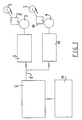
- the winder shown in figure 1 is provided to wind two fabrics as they are woven on a weaving machine.
- the winder comprises two winding cylinders (1),(2) which may be driven by means of respective torque motors (3),(4) to wind a respective fabric.
- the torques (T mot ) developed by these torque motors (3),(4) may be controlled by means of respective frequency converters (5),(6), the output frequency of which is kept constant and of which only the activating or desired voltage (V 1 ) is modified as a function of the average motor voltage (V mot ).
- This desired voltage (V 1 ) is calculated pro-actively by the weaving machine control (7) in accordance with a mathematical model as a function of a number of parameters stored in the weaving machine and/or are calculated by this control in the course of the weaving process.
- the activating voltage (V 1 ) for the frequency converters calculated in accordance with the mathematical model is transferred digitally, via a serial line or a field bus (8), to the control of the frequency converters (5),(6) the output voltage (V mot ) of which is applied to the torque motor.
- V mot the output voltage of which is applied to the torque motor.
- Via a respective motor the torque developed by each geared motor unit (9),(10) (with a total efficiency ⁇ and a ratio i) transferred to the winding cylinders (1),(2).
- an input console (11) is provided, allowing a number of parameters to be entered into the weaving machine control and subsequently to be stored in the fabric characteristics file. This device functions very efficiently and is economic.
- the motors of the winder may be activated in such a way that the exact tractive force (F w ), adapted to the fabric characteristics, is adjusted right from the initial winding diameter (D 0 ), and that this tractive force (F w ) is kept at a constant value during the weaving process and when the weaving machine is at a standstill until the final winding diameter for a given weaving length (l w ) on the cylinder is reached.
- T w 0.5*F w * 4*s w *l w / ⁇ + d 0 2
- V mot applied to a motor (3),(4) by a frequency converter (5),(6) is proportional to the control or desired voltage V 1 which is applied to the converter (5),(6).
- V mot c 1 *V 1
- T mot c 2 *V mot 2 *f( ⁇ )
- the motor temperature ⁇ is calculated by the machine control, because the switching on torque of the torque motor for normal ambient temperatures is known to this control, and also the control value of the voltage for the motor control.
- T red ⁇ *i*c 2 *c 1 2 *V 1 2 *f( ⁇ )
- ⁇ *i*c 2 *c 1 2 *V i 2 *f( ⁇ ) 0.5*F w * 4*s w *l w / ⁇ +d 0 2 from which V 1 can be calculated:
- V i 0,5*F w * 4*s w *l w / ⁇ + d 0 2 ⁇ * i * c 2 * c 1 2 * f( ⁇ )
- the total voltage to be applied to the converter is the total of the voltage (V iO ) which has to be applied when the winding is started (at the initial winding diameter (d 0 ) and the calculated control voltage (V i ):
- V c V iO + V i
- the activating voltage (V i ) of the converter can be calculated pro-actively by the weaving machine control as a function of a number of parameters which have been stored in the weaving control and/or are calculated during the running time.
- the calculation frequency may be low, for instance each 500 ms of each second.
- the adjustments for winding force (F w ), winding length (l w ) on the cylinder, thickness of the fabric (s w ), and weft density (S) can be stored in the fabric characteristics file in the weaving machine control.
- the initial winding diameter (d 0 ) can be entered and, if necessary, be adapted via the input console (11) of the control.
- the number of weft really woven is inquired from the pick counter of the weaving machine during the weaving process.
- the number of woven weft threads is registered by the pick counter. From this information and from the weft density (S) the woven length (l w ) is calculated by the machine control (7).
- the motor temperature ⁇ is calculated by the machine control from the registered period of operation of the motor (3),(4), the voltage V mot applied to the motor (3),(4), which is known by the control (7) and the warming up characteristics of the torque motor (3),(4).
- V i the value of the control voltage (V i ) is calculated, for instance every 500 ms, by the machine control, by means of the formula given before, in order to obtain the constant tractive force (F w ) desired.
- the calculated value (V i ) is transferred digitally to the frequency converter (5),(6), which in turn applies an output voltage V mot to the torque motor (3),(4), resulting in a motor torque (T mot ) and an output torque T red transferred to the winding cylinder (1),(2), which finally produces the desired tractive force (F w ) on the fabric.
- This device functions very efficiently and is particularly economic.
Landscapes
- Looms (AREA)
- Controlling Rewinding, Feeding, Winding, Or Abnormalities Of Webs (AREA)
- Winding Filamentary Materials (AREA)
Claims (20)
- Verfahren zum Steuern/Regeln einer Aufwickelvorrichtung, in welchem während des Aufwickelprozesses das Aufwickeldrehmoment (TW) als eine Funktion der Sollzugkraft (Fw) in dem aufgewickelten Material gesteuert/geregelt wird,
dadurch gekennzeichnet, dass während des Aufwickelns wiederholtder Wert einer das Aufwickeldrehmoment (TW) beeinflussenden Größe (Vi) berechnet wird, wobei bei jeder Berechnung ein zu entwickelndes Aufwickeldrehmoment (TW) angenommen wird, welches aus der Sollzugkraft (FW), dem Anfangsaufwickeldurchmesser (d0), der Dicke (sw) und der aufgewickelten Länge (lw) des Materials bestimmt wird, undeine Einstellung der Größe (Vi) ausgeführt wird, wobei der berechnete Wert als ein Richtwert verwendet wird. - Verfahren zum Steuern/Regeln einer Aufwickelvorrichtung nach Anspruch 1,
dadurch gekennzeichnet, dass das zu entwickelnde Aufwickeldrehmoment (Tw) mittels der folgenden Formel bestimmt wird: - Verfahren zum Steuern/Regeln einer Aufwickelvorrichtung nach einem beliebigen der vorhergehenden Ansprüche,
dadurch gekennzeichnet, dass die Größe eine an einer Ansteuerungsvorrichtung (3,9), (4,10) oder eine Steuer-/Regelvorrichtung (5,6,7,8,11) anzulegende Steuer-/Regelspannung (Vi) ist und dass ihre Steuer-/Regelspannung (Vi) mittels einer Formel berechnet wird, welche erhalten wird durch Abgleichen des zu entwickelnden Windungsdrehmoments (Tw), ausgedrückt als eine Funktion der Sollzugkraft (Fw), an das Ausgangsdrehmoment (Tred) der Ansteuerungsvorrichtung (3,9), (4,10), ausgedrückt als eine Funktion der Steuer-/Regelspannung (Vi). - Verfahren zum Steuern/Regeln einer Aufwickelvorrichtung nach einem beliebigen der vorhergehenden Ansprüche,
dadurch gekennzeichnet, dass der Aufwickelkörper mittels eines Elektromotors drehbar ist und dass die Einstellung der Größe (Vi) zu einer Einstellung der an diesen Elektromotor (3), (4) angelegten Spannung (Vmot) führt. - Verfahren zum Steuern/Regeln einer Aufwickelvorrichtung nach Anspruch 4,
dadurch gekennzeichnet, dass der Elektromotor mittels eines Frequenzwandlers gesteuert/geregelt wird und dass die Größe die an diesen Frequenzwandler anzulegende Steuer-/Regelspannung (Vi) ist. - Verfahren zum Steuern/Regeln einer Aufwickelvorrichtung nach einem beliebigen der vorhergehenden Ansprüche,
dadurch gekennzeichnet, dass das Material ein Gewebe, insbesondere ein Polgewebe ist. - Verfahren zum Steuern/Regeln einer Aufwickelvorrichtung nach Anspruch 5 oder 6,
dadurch gekennzeichnet, dass die Steuer-/Regelspannung (Vi) mittels der folgenden Formel berechnet wird:Fw die Sollzugkraft ist,Sw die Dicke des Material ist,lw die aufgewickelte Länge des Materials ist,d0 der Anfangsaufwickeldurchmesser ist,η der Wirkungsgrad der Getriebemotoreinheit ist,i das Übersetzungsverhältnis des Untersetzungsgetriebes ist,ci das Verhältnis zwischen der an den Motor angelegten Spannung (Vmot) und der an den Frequenzumwandler anzulegenden Steuer-/Regelspannung (Vi) ist,c2 das Verhältnis zwischen dem durch den Motor entwickelten Drehmoment (Tmot) einerseits und dem mit einem Parameter f() multiplizierten Quadrat der an den Motor angelegten Spannung (Vmot) andererseits ist undf() ein Parameter ist, welcher nach Maßgabe einer bestimmten Funktion abhängig von der Temperatur des Motors ist. - Verfahren zum Steuern/Regeln einer Aufwickelvorrichtung nach einem beliebigen der vorhergehenden Ansprüche,
dadurch gekennzeichnet, dass das Material ein Gewebe ist, dass das Gewebe während seines Webprozesses auf einer Webmaschine aufgewickelt wird und dass die aufgewickelte Länge (lw) während des Aufwickelns berechnet wird, indem die Anzahl an Schussfäden (Nw - Nw0), welche von dem Moment an eingeführt worden sind, in dem das Aufwickeln auf der Webmaschine begonnen wurde, durch die Schussdichte (S) geteilt wird. - Verfahren zum Steuern/Regeln einer Aufwickelvorrichtung nach Anspruch 8,
dadurch gekennzeichnet, dass die Anzahl an Schussfäden (Nw - Nw0) durch einen Schusszähler an der Webmaschine bestimmt wird. - Verfahren zum Steuern/Regeln einer Aufwickelvorrichtung nach einem beliebigen der vorhergehenden Ansprüche,
dadurch gekennzeichnet, dass die Sollzugkraft während des Aufwickelns praktisch konstant ist. - Verfahren zum Steuern/Regeln einer Aufwickelvorrichtung nach einem beliebigen der vorhergehenden Ansprüche,
dadurch gekennzeichnet, dass die Größe während des Aufwickelns mit einer Frequenz von nicht mehr als zwei mal pro Sekunde berechnet und gesteuert/geregelt wird. - Vorrichtung zum Steuern/Regeln einer Aufwickelvorrichtung,
umfassend Mittel zum automatischen Steuern/Regeln des Aufwickeldrehmoments der Aufwickelansteuerungsvorrichtung (3,9), (4,10) (Tw) als eine Funktion der Sollzugkraft (Fw) in dem aufzuwickelnden Material,
dadurch gekennzeichnet, dass während des Aufwickelns die Vorrichtung dafür ausgelegt ist, dass sie wiederholtden Wert einer das Aufwickeidrehmoment (Tw) beeinflussenden Größe (Vi) berechnet, wobei bei jeder Berechnung ein zu entwickelndes Aufwickeldrehmoment (TW) angenommen wird, welches aus der Sollzugkraft (FW), dem Anfangsaufwickeldurchmesser (d0), der Dicke (sw) und der aufgewickelten Länge (lw) des Materials bestimmt wird, undeine Einstellung der Größe (Vi) ausführt, wobei der berechnete Wert als ein Richtwert verwendet wird. - Vorrichtung zum Steuern/Regeln einer Aufwickelvorrichtung nach Anspruch 12,
dadurch gekennzeichnet, dass das zu entwickelnde Aufwickeldrehmoment (Tw) mittels der folgenden Formel bestimmt wird: - Vorrichtung zum Steuern/Regeln einer Aufwickelvorrichtung nach Anspruch 12 oder 13,
dadurch gekennzeichnet, dass die Größe (Vi) eine Steuer-/Regelspannung (Vi) ist und dass diese Steuer-/Regelspannung (Vi) mittels einer Formel berechnet wird, welche durch Abgleichen des zu entwickelnden Aufwickeldrehmoments (Tw), ausgedrückt als eine Funktion der Sollzugkraft (Fw), mit dem Ausgangsdrehmoment (Tred) der Ansteuerungsvorrichtung, ausgedrückt als eine Funktion der Steuer-/Regelspannung (Vi), erhalten wird. - Vorrichtung zum Steuern/Regeln einer Aufwickelvorrichtung nach Anspruch 14,
dadurch gekennzeichnet, dass sie einen Frequenzumwandler umfasst, dass die Größe einer an den Frequenzumwandler anzulegende Steuer-/Regelspannung (Vi) ist und dass die Steuer-/Regelspannung (Vi) aus der folgenden Formel berechnet wird:Fw die Sollzugkraft ist,Sw die Dicke des Material ist,lw die aufgewickelte Länge des Materials ist,d0 der Anfangsaufwickeldurchmesser ist,η der Wirkungsgrad der Getriebemotoreinheit ist,i das Übersetzungsverhältnis des Untersetzungsgetriebes ist,ci das Verhältnis zwischen der an den Motor angelegten Spannung (Vmot) und der an den Frequenzumwandler anzulegenden Steuer-/Regelspannung (Vi) ist,c2 das Verhältnis zwischen dem durch den Motor entwickelten Drehmoment (Tmot) einerseits und dem mit einem Parameter f() multiplizierten Quadrat der an den Motor angelegten Spannung (Vmot) andererseits ist undf() ein Parameter ist, welcher nach Maßgabe einer bestimmten Funktion abhängig von der Temperatur des Motors ist. - Vorrichtung zum Aufwickeln eines Materials nach einem beliebigen der Ansprüche 12 bis 15,
dadurch gekennzeichnet, dass das Material ein Gewebe ist, welches während seines Webens aufgewickelt wird, und dass die aufgewickelte Länge (lw) während des Aufwickelns berechnet wird, indem die Anzahl an Schussfäden (Nw - Nw0), welche von dem Moment an eingeführt worden sind, in dem das Aufwickeln auf der Webmaschine begonnen wurde, durch die Schussdichte (S) geteilt wird. - Vorrichtung zum Steuern/Regeln einer Aufwickelvorrichtung nach Anspruch 16,
dadurch gekennzeichnet, dass die Anzahl an Schussfäden (Nw - Nw0), welche eingeführt worden ist, durch einen Schusszähler an der Webmaschine bestimmt wird. - Vorrichtung zum Steuern/Regeln einer Aufwickelvorrichtung nach einem beliebigen der Ansprüch 12 bis 17,
dadurch gekennzeichnet, dass die Steuer-/Regelvorrichtung dafür vorgesehen ist, den Wert (Vi) während des Aufwickelns mit einer Frequenz von nicht mehr als zweimal pro Sekunde zu berechnen und einzustellen. - Aufwickelvorrichtung, umfassend einen Aufwickelkörper (1), (2) zum Aufwickeln eines Materials, einer Ansteuerungsvorrichtung (3,9), (4,10) zum Ansteuern dieses Aufwickelkörpers (1), (2) und eine Vorrichtung (5,6,7,8,11) zum Steuern/Regeln der Aufwickelvorrichtung, welche vorgesehen ist für eine automatische Steuerung/Regelung des Aufwickeldrehmoments der Ansteuerungsvorrichtung als Funktion der Sollzugkraft (Fw) in dem Material, welches aufgewickelt wird,
dadurch gekennzeichnet, dass die Vorrichtung zum Steuern/Regeln der Aufwickelvorrichtung eine Vorrichtung nach einem beliebigen der Ansprüche 12 bis 18 ist. - Aufwickelvorrichtung nach Anspruch 19, dadurch gekennzeichnet, dass sie eine Aufwickelvorrichtung für ein Gewebe, insbesondere für ein Polgewebe ist.
Applications Claiming Priority (2)
| Application Number | Priority Date | Filing Date | Title |
|---|---|---|---|
| BE200100496 | 2001-07-20 | ||
| BE2001/0496A BE1014308A5 (nl) | 2001-07-20 | 2001-07-20 | Werkwijze en inrichting voor het sturen van een opwikkelinrichting. |
Publications (2)
| Publication Number | Publication Date |
|---|---|
| EP1277682A1 EP1277682A1 (de) | 2003-01-22 |
| EP1277682B1 true EP1277682B1 (de) | 2005-11-23 |
Family
ID=3897064
Family Applications (1)
| Application Number | Title | Priority Date | Filing Date |
|---|---|---|---|
| EP02077881A Expired - Lifetime EP1277682B1 (de) | 2001-07-20 | 2002-07-17 | Verfahren und Vorrichtung zum Steuern einer Aufwickeleinrichtung |
Country Status (4)
| Country | Link |
|---|---|
| US (1) | US6828743B2 (de) |
| EP (1) | EP1277682B1 (de) |
| BE (1) | BE1014308A5 (de) |
| DE (1) | DE60207495T2 (de) |
Families Citing this family (13)
| Publication number | Priority date | Publication date | Assignee | Title |
|---|---|---|---|---|
| JP4264015B2 (ja) * | 2003-08-01 | 2009-05-13 | 津田駒工業株式会社 | 繊維機械における巻径の算出方法及び装置 |
| US6903525B2 (en) * | 2003-08-05 | 2005-06-07 | Kendro Laboratory Products, Lp | Motor temperature sensor system and method to determine motor performance |
| DE102005044339B4 (de) * | 2005-09-16 | 2016-01-14 | Siemens Aktiengesellschaft | Verfahren zum Betrieb einer Wicklermaschine |
| US8032246B2 (en) * | 2007-02-02 | 2011-10-04 | Kimberly-Clark Worldwide, Inc. | Winding method for uniform properties |
| FI119806B (fi) * | 2007-02-06 | 2009-03-31 | Metso Paper Inc | Menetelmä käytön kapasiteettireservin hyödyntämiseksi kuiturainan rullauksessa |
| DE102007007988A1 (de) * | 2007-02-17 | 2008-08-28 | Robert Bosch Gmbh | Verfahren und Vorrichtung zur Reibkompensation |
| BE1023564B1 (nl) * | 2015-11-03 | 2017-05-05 | VAN DE WIELE Michel NV | Garenspanningssysteem en werkwijze voor het onder spanning houden van een garen dat van een garenopslagsysteem afgenomen wordt naar een garenafneemsysteem van een weefmachine toe |
| US10532422B2 (en) * | 2015-12-28 | 2020-01-14 | Hitachi Metals, Ltd. | Clad material and electronic device housing |
| PL3478614T3 (pl) * | 2016-06-29 | 2024-09-02 | Ranpak Corp. | Urządzenie i sposób wytwarzania zwoju materiału sztauerskiego |
| US10758966B2 (en) | 2018-02-21 | 2020-09-01 | Newfrey Llc | Processor-controlled tape feed apparatus and method for a self-piercing rivet machine |
| US10456826B2 (en) | 2018-02-21 | 2019-10-29 | Newfrey Llc | Tape feed apparatus and method for a self-piercing rivet machine |
| US10780489B2 (en) | 2018-02-21 | 2020-09-22 | Newfrey Llc | Tool-free opening tape feed receiver for a self-piercing rivet machine |
| US11130652B2 (en) * | 2018-05-03 | 2021-09-28 | Nv Michel Van De Wiele | Yarn tensioning system and method for keeping a yarn which is taken from a yarn storage system to a yarn take-off system of a weaving machine under tension |
Family Cites Families (8)
| Publication number | Priority date | Publication date | Assignee | Title |
|---|---|---|---|---|
| JPS5232035B2 (de) * | 1972-07-17 | 1977-08-18 | ||
| US3910521A (en) * | 1972-12-21 | 1975-10-07 | Eaton Corp | Winder control |
| JPS6031733B2 (ja) * | 1973-07-06 | 1985-07-24 | 株式会社片岡機械製作所 | 巻取張力制御装置 |
| US4146190A (en) * | 1977-12-02 | 1979-03-27 | Bond Textile Machinery, Inc. | Web winding control system |
| DE9216261U1 (de) * | 1992-10-19 | 1994-02-24 | Windmöller & Hölscher, 49525 Lengerich | Vorrichtung zum Aufwickeln einer Bahn |
| US5623189A (en) * | 1994-08-19 | 1997-04-22 | Hemmer; Ferdinand J. | Automatic control of torque or force at moving loads |
| EP0745890A1 (de) * | 1995-05-30 | 1996-12-04 | Eastman Kodak Company | Bewegungssteuerungssystem für Filmband |
| CH692340A5 (de) * | 1997-05-09 | 2002-05-15 | Hunkeler Ag Papierverarbeitung | Aufwickelvorrichtung für eine Papier-, Textil-, Kunststoff- oder andere Stoffbahn und Verfahren zum Aufwickeln von solchen Bahnen. |
-
2001
- 2001-07-20 BE BE2001/0496A patent/BE1014308A5/nl not_active IP Right Cessation
-
2002
- 2002-07-17 DE DE60207495T patent/DE60207495T2/de not_active Expired - Lifetime
- 2002-07-17 EP EP02077881A patent/EP1277682B1/de not_active Expired - Lifetime
- 2002-07-22 US US10/199,491 patent/US6828743B2/en not_active Expired - Fee Related
Also Published As
| Publication number | Publication date |
|---|---|
| US20030015981A1 (en) | 2003-01-23 |
| BE1014308A5 (nl) | 2003-08-05 |
| DE60207495D1 (de) | 2005-12-29 |
| US6828743B2 (en) | 2004-12-07 |
| EP1277682A1 (de) | 2003-01-22 |
| DE60207495T2 (de) | 2006-08-03 |
Similar Documents
| Publication | Publication Date | Title |
|---|---|---|
| EP1277682B1 (de) | Verfahren und Vorrichtung zum Steuern einer Aufwickeleinrichtung | |
| DE10135542B4 (de) | Verfahren zur Steuerung eines Rollenspeichers und Rollenspeicher zum Speichern blattförmiger Gegenstände | |
| US4407331A (en) | Speed regulator for the warp beam of a weaving machine | |
| EP0057523B1 (de) | Längsschneidumroller | |
| US7770271B2 (en) | Method and device for operating a creel designed for a winding system and corresponding creel | |
| PL178451B1 (pl) | Sposób regulacji naciągu taśmy, nawijanej na rolkę | |
| DE19512963C2 (de) | Vorrichtung zum Abziehen von Bändern | |
| US3977621A (en) | Differential driven rewinder-unwinder | |
| JPS6094652A (ja) | 繰出し装置の回転駆動装置を調整する装置 | |
| EP2206667B1 (de) | Verfahren im Zusammenhang mit einem Abwickler | |
| JPH0151422B2 (de) | ||
| JPH08231101A (ja) | 張力制御装置 | |
| JPH0220545B2 (de) | ||
| DE3713915A1 (de) | Elektrische zugkraft-regelvorrichtung fuer wickelvorgaenge | |
| CN108622698B (zh) | 控制用于纤维幅材的卷绕机的操作的方法 | |
| EP2905246B1 (de) | Verfahren und system zur einstellung der spannung beim aufwickeln für eine maschine mit einer wickelstation | |
| EP0550356B1 (de) | Digitale PID-Regelung | |
| US4448366A (en) | Coil diameter tracking system and tension regulation system using such tracking system | |
| JPH07315653A (ja) | 巻取機制御装置 | |
| TWI671993B (zh) | 轉矩模式馬達驅動裝置 | |
| JP3035132B2 (ja) | リワインダ制御装置 | |
| EP4417741B1 (de) | Verfahren zum kontrollierten spannen von kettfäden in einer textilmaschine und zugehörige textilmaschine | |
| Dapcevic et al. | Structuring of winder drive software-review of basic building blocks | |
| DE2030242C3 (de) | Wickeleinrichtung für konstante Bahnspannung | |
| JP3601132B2 (ja) | 帯状シート巻取装置の速度設定装置 |
Legal Events
| Date | Code | Title | Description |
|---|---|---|---|
| PUAI | Public reference made under article 153(3) epc to a published international application that has entered the european phase |
Free format text: ORIGINAL CODE: 0009012 |
|
| AK | Designated contracting states |
Kind code of ref document: A1 Designated state(s): AT BE BG CH CY CZ DE DK EE ES FI FR GB GR IE IT LI LU MC NL PT SE SK TR |
|
| AX | Request for extension of the european patent |
Free format text: AL;LT;LV;MK;RO;SI |
|
| 17P | Request for examination filed |
Effective date: 20030227 |
|
| AKX | Designation fees paid |
Designated state(s): DE IT TR |
|
| 17Q | First examination report despatched |
Effective date: 20030922 |
|
| GRAP | Despatch of communication of intention to grant a patent |
Free format text: ORIGINAL CODE: EPIDOSNIGR1 |
|
| GRAS | Grant fee paid |
Free format text: ORIGINAL CODE: EPIDOSNIGR3 |
|
| GRAA | (expected) grant |
Free format text: ORIGINAL CODE: 0009210 |
|
| AK | Designated contracting states |
Kind code of ref document: B1 Designated state(s): DE IT TR |
|
| REF | Corresponds to: |
Ref document number: 60207495 Country of ref document: DE Date of ref document: 20051229 Kind code of ref document: P |
|
| PLBE | No opposition filed within time limit |
Free format text: ORIGINAL CODE: 0009261 |
|
| STAA | Information on the status of an ep patent application or granted ep patent |
Free format text: STATUS: NO OPPOSITION FILED WITHIN TIME LIMIT |
|
| 26N | No opposition filed |
Effective date: 20060824 |
|
| PGFP | Annual fee paid to national office [announced via postgrant information from national office to epo] |
Ref country code: TR Payment date: 20200717 Year of fee payment: 19 Ref country code: DE Payment date: 20200721 Year of fee payment: 19 |
|
| PGFP | Annual fee paid to national office [announced via postgrant information from national office to epo] |
Ref country code: IT Payment date: 20200724 Year of fee payment: 19 |
|
| REG | Reference to a national code |
Ref country code: DE Ref legal event code: R119 Ref document number: 60207495 Country of ref document: DE |
|
| PG25 | Lapsed in a contracting state [announced via postgrant information from national office to epo] |
Ref country code: DE Free format text: LAPSE BECAUSE OF NON-PAYMENT OF DUE FEES Effective date: 20220201 |
|
| PG25 | Lapsed in a contracting state [announced via postgrant information from national office to epo] |
Ref country code: IT Free format text: LAPSE BECAUSE OF NON-PAYMENT OF DUE FEES Effective date: 20210717 |