EP1277549A1 - Anordnung zum Zuführen von Bolzen zu einem Bolzenschubgerät - Google Patents
Anordnung zum Zuführen von Bolzen zu einem Bolzenschubgerät Download PDFInfo
- Publication number
- EP1277549A1 EP1277549A1 EP02016223A EP02016223A EP1277549A1 EP 1277549 A1 EP1277549 A1 EP 1277549A1 EP 02016223 A EP02016223 A EP 02016223A EP 02016223 A EP02016223 A EP 02016223A EP 1277549 A1 EP1277549 A1 EP 1277549A1
- Authority
- EP
- European Patent Office
- Prior art keywords
- bolt
- arrangement according
- magazine
- guide
- bolts
- Prior art date
- Legal status (The legal status is an assumption and is not a legal conclusion. Google has not performed a legal analysis and makes no representation as to the accuracy of the status listed.)
- Withdrawn
Links
- 230000000903 blocking effect Effects 0.000 claims description 8
- 230000006835 compression Effects 0.000 claims description 4
- 238000007906 compression Methods 0.000 claims description 4
- 238000006073 displacement reaction Methods 0.000 claims description 3
- 230000001960 triggered effect Effects 0.000 claims description 2
- 238000011161 development Methods 0.000 description 7
- 230000018109 developmental process Effects 0.000 description 7
- 230000006378 damage Effects 0.000 description 2
- 230000000694 effects Effects 0.000 description 2
- 239000000463 material Substances 0.000 description 2
- 229910000831 Steel Inorganic materials 0.000 description 1
- 208000027418 Wounds and injury Diseases 0.000 description 1
- 150000001875 compounds Chemical class 0.000 description 1
- 230000002349 favourable effect Effects 0.000 description 1
- 208000014674 injury Diseases 0.000 description 1
- 230000003993 interaction Effects 0.000 description 1
- 238000004519 manufacturing process Methods 0.000 description 1
- 238000000034 method Methods 0.000 description 1
- 238000003825 pressing Methods 0.000 description 1
- 239000003380 propellant Substances 0.000 description 1
- 230000000284 resting effect Effects 0.000 description 1
- 239000010959 steel Substances 0.000 description 1
- 238000003860 storage Methods 0.000 description 1
Images


Classifications
-
- B—PERFORMING OPERATIONS; TRANSPORTING
- B25—HAND TOOLS; PORTABLE POWER-DRIVEN TOOLS; MANIPULATORS
- B25C—HAND-HELD NAILING OR STAPLING TOOLS; MANUALLY OPERATED PORTABLE STAPLING TOOLS
- B25C1/00—Hand-held nailing tools; Nail feeding devices
- B25C1/08—Hand-held nailing tools; Nail feeding devices operated by combustion pressure
- B25C1/10—Hand-held nailing tools; Nail feeding devices operated by combustion pressure generated by detonation of a cartridge
- B25C1/18—Details and accessories, e.g. splinter guards, spall minimisers
- B25C1/182—Feeding devices
- B25C1/184—Feeding devices for nails
Definitions
- the invention is based on a bolt pusher with whose help Steel existing bolts can be shot into an underground, for example with the help of propellant charge cartridges.
- Bolt thrusters this Art often have an option to have multiple bolts or nails in a row to put.
- the bolts are in a mainly plastic Strip attached, which is fed to the device. This is to achieve that a user can put several bolts in a row without after each Process of having to insert a new bolt into the device.
- the housing contains in its front Area a laterally protruding magazine that holds the fasteners serves.
- the magazine is attached to the housing in one piece and is formed by a tube with a square cross section. The bolts will be inserted from the outer end face (EP 522996 B).
- the magazine is welded on Hollow profile formed, in which the fasteners in a Plastic strips are housed, from the opposite of the magazine Side.
- the invention is based on the object, the handling of bolt pushers to improve.
- the invention proposes an arrangement with the Claim 1 mentioned features. Developments of the invention are the subject of subclaims.
- the invention therefore proposes an arrangement in which on the bolt pusher a bolt magazine can be attached in which the bolts are housed are.
- the bolts act if they are in the bolt channel of the bolt guide are inserted together with a locking element that triggers of the bolt pusher. As soon as the magazine is emptied, or the locking element prevents the bolts from being replenished for another reason triggering the device.
- the fasteners are from the feeder in the direction of the bolt channel.
- the device for conveying the bolt has a slide movable by a spring on the last bolt the row or bracket for this attacks and the bolt towards acted on the canal.
- it can be a Act helical compression spring. This is one that works with great reliability Element that hardly changes its properties even after long use.
- the locking element in its Locked position on the bolt guide attacks to prevent their displacement.
- the bolt guide is usually used to move the device into one position in which a shot can be placed.
- the device is used for this the mouth of the bolt guide placed on the surface and pressed.
- the invention now proposes to arrange the locking element in such a way that it prevents the bolt guide from shifting when the bolt channel is empty.
- the locking element can be moved or can be stored movably. It has turned out to be particularly favorable to pivotally mount the locking element, in particular on a mounting ring surrounding the bolt guide.
- the locking element can advantageously be loaded into the locking position under the action of a spring.
- the Locked position is designed such that it locks itself. With that achieved that the lock is not overcome even with great effort can be. This possibility can be designed accordingly the interaction of locking element and bolt guide can be achieved.
- the locking element as a pawl is formed, which preferably engages two on a step of the bolt guide Has webs.
- the level of the bolt guide can be designed in this way be that it forms a certain undercut so that the two webs, or even a single bar, not out of step in the locked position itself can be moved out, but only for this a backward movement the bolt guide must be possible.
- the pawl can have two lateral Have wings on which it is mounted. These side wings can do so be arranged and designed so that the bolt guide between them lock in.
- a further development of the invention can provide that the wings and the webs of the pawl are each arranged in levels, and that the plane of the webs on the one hand and the plane of the wings on the other run perpendicular to each other. This will ensure great stability of the Pawl reached, so that there is a great deal of security and none at all There is a risk of closing the locking position by destroying the locking element overcome.
- the pawl has a middle Finger, which through a longitudinally extending slot of the bolt guide reaches through. This finger can then be used in the pin channel arranged nail, or in other words, the finger serves to to sense the presence of a bolt in the bolt channel.
- the bolt magazine with the help an adapter is attached to the bolt guide.
- the connection can also be a detachable connection.
- the bolt magazine can be made of plastic, since it does not have to have any particular strength.
- the adapter can for example be designed so that he the bolt guide with the exception of Surrounds the muzzle, which must remain clear, so that the muzzle of the bolt guide can be placed on the surface.
- the Locking pawl or the locking element can be accommodated within the adapter, so that a protected space is created here that also protects against pollution and manipulation attempts are protected.
- the bolt magazine transversely to The axis of the bolt guide runs, which facilitates the feeding of the individual bolts.
- the bolt magazine can preferably be elongated and straight his.
- the bolts that are also housed in a plastic strip in the invention are that they can run parallel to each other and at a distance especially through a side slot or opening in the side Magazine can be used.
- Side is understood to mean that starting a narrow side can be understood from the longitudinal direction of the magazine should.
- the bolts are therefore no longer radially outer or radial inner end face inserted into the magazine, but from a side edge. This means that less space is required to insert the bolts.
- the slot is covered can, so that during use there is no risk of damage, injury or pollution.
- the bolt magazine is preferably one with the adapter integrally connected core, the one Includes guide for the magazine bolts.
- a shell can be provided which is displaceable in the longitudinal direction of the magazine is. To open it, the tray is moved laterally by the magazine, until the opening is fully open. The cover still attached to the magazine so that they are not lost either can go.
- the core can be a guide for the cover have forming shell.
- the shell contains the core in a essentially transverse to the longitudinal direction of the magazine completely surrounds.
- the core can in particular have the cross-sectional shape of a U, which results in Guide the bolt having a head is particularly suitable.
- the bolts can be held in the magazine so that they pass through an opening inserted into the bolt channel in the jacket of the bolt guide can.
- This opening can be an elongated hole, i.e. one limited opening on all sides.
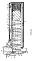
- Figure 1 shows a section of a filled bolt magazine that with the help of a Adapter 1 is attached to a bolt guide 2.
- the magazine contains one Core 3, which is surrounded by a shell 4.
- the bolt guide 2, which is part of a Bolt-setting device is, contains a bolt channel 5, which is an axis of the device Are defined.
- the lower end of the pin guide 2 in FIG. 1 forms an opening 6, which must be arranged outside the adapter.
- With a compound Device protrudes this mouth 6 of the bolt guide 5 out of the device. When using the device, this mouth 6 is on the ground or the object to be fastened and pressed.
- the bolt guide 2 is surrounded by a mounting ring 7, which has a flange 8 forms. Compared to this mounting ring 7, the bolt guide 2 is shown in the Position can be shifted upwards by a certain amount.
- the Possibility of shifting the pin guide 2 relative to the landing ring 7 is realized in the device itself, which is here for the sake of simplification is not shown.
- the core 3 of the bolt magazine points upward in FIG. 1 its longitudinally extending slot, which therefore forms a lateral opening, if you start from the longitudinal direction of the magazine.
- the opening 14 is intended to insert a plastic strip 9 with the contained therein Allow bolts 10.
- the adapter with the help of which the bolt magazine is attached to the bolt guide 2 is designed so that it surrounds the bolt guide and partially is at a distance from it, so that the contact ring 7 also partially comes to lie within the adapter 1.
- a locking element 15 is arranged, the effect of which later is described.
- Figure 2 shows an enlarged view compared to Figure 1 Scale a partially broken cut through the pin guide 2 and the landing ring 7.
- the landing ring 7 is connected to the outer one Flange 8 has a pot-like area 16, the bottom 17 of which has an opening 18 contains.
- the opening 18 is selected such that the one shown broken off in the figure The core of the bolt guide 2 fits through it.
- the landing ring 7 has on his Bottom 17, on its underside facing away from the flange 8 two side cheeks 19, see also Figure 4. These two Cheeks 19 are outside the diameter of the bolt guide 2 in this Area arranged.
- the cheeks 19 are used to support a shaft 20 which the locking element 15 can be pivotally mounted. This is in Figure 2 also hinted at.
- FIG. 2 shows the blocking element 5 in its blocking position, into which it can only be reached the lack of a pin can be brought, which is not shown in Figure 2 is.
- the Locking element 15 is designed in the embodiment shown as a pawl, which can be pivoted about the already mentioned shaft 20.
- the Pawl has two webs 21 lying in one plane, which are is actually a single web, which is divided by an incision 22 is.
- On the two opposite side edges of the two Crosspieces 21 each have a wing 23 angled at 90 °, which is used for storage serves.
- the two wings 23 have two aligned bearing openings 24 on. With these bearing openings 24, the vanes 23 are mounted on the shaft 20.
- FIG. 2 shows the blocking element 15 in the blocking position.
- the locking element can be removed from the locked position of FIG. 2 when a certain Clearance between the end of the webs 21 and the bottom of the recess is present, by inserting a bolt 10 into the bolt channel 5 can be moved into the release position.
- the provided with the bolt 10 Plastic bar 9 engages at the end of finger 26 and pivots the pawl from the position of Figure 2 clockwise, so that now the ends of the webs 21 out of engagement with the bottom 25 of the recess reach.
- the pin guide 2 in Figure 2 can be moved upwards in order to bring the device into a position in which a shot can be triggered.
- Figure 4 shows the arrangement of Figure 2 from a direction offset by 90 °.
- the two wings 23 of the pawl are between the inside of the cheeks 19 of the mounting ring 7 and the bolt guide 2 are arranged.
- the finger 26 is arranged in the center, so that the plastic strip 9 when it is in the bolt channel 5 is pushed, the finger 26 sees.
- the pawl is in shown their locked position.
- Figure 5 shows a partial view of the pin guide 2 from the left in Figure 2.
- the pawl is in the middle between the two webs 21 then an elongated hole 27 is formed in the wall of the bolt guide, through which the Finger 26 can reach through.
- the slot 27 is dimensioned so that the mentioned displacement of the pin guide 2 relative to the contact ring 7 is possible. Also lies in the release position, which can be seen in FIG Finger 26 within the elongated hole 27.
- FIG 2 shows that the webs 21 when tried will push the bolt guide 2 upwards in its own plane Thrust are claimed, and that the wings 23, which are mounted in at their own level. So it's about training the pawl around a very stable arrangement in terms of security requirements the establishment.
- FIG. 1 It can be seen from FIG. 1 that a spring 28 is present, which is the locking element 15 applied in the direction of the locked position. One end comes into effect in FIG. 1 the spring 28 on the outside of the webs 21.
- the adapter 1 can be seen in section in FIG. It contains an upper one Flange 29, which rests on the underside of the flange 8 of the attachment ring 7. in the upper area, the inner diameter of the adapter 1 corresponds to the outer diameter of the pot-like part 16 of the attachment ring. Then the will decrease Diameter of the adapter over a sloping step 30 into a lower one Part where the inside diameter of the adapter matches the outside diameter of the Bolt guide 2 corresponds in this area.
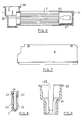
- the adapter 1 is molded in one piece from plastic and is already mentioned Core 3, which is drawn in the middle area in FIG. 6, on the right Area but on average.
- the core 3 of the magazine contains a bottom 31, which is limited by the end wall 13 mentioned.
- the outside of the core has a profile that is used to guide the cover, the is shown in Figure 7.
- the adapter 1 and the core 3 of the magazine exist from a single piece, while the cover 4 from two connected together Shells is built. As a result, the bolt magazine exists as a whole only in three parts, if you ignore possible screws.
- Figure 8 shows a cross section through the core 3 of the bolt magazine.
- the Cross section is approximately U-shaped with an open top that the Opening 14 forms.
- the interior is elongated with parallel side walls and a bottom that is rounded.
- the interior corresponds approximately the shape of the bolt 10 or the plastic strip 9. Both on the outside Profiles of the core present on the right and left provide grooves 32 represents that serve to take the leadership for the cover 14.
- Figure 9 shows a cross section through the adapter with the slot-like opening 33, which allows the plastic strip 9 to be pushed through with the bolts 10.
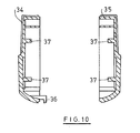
- the cover is from a left bowl 34 and a right shell 35 is constructed.
- one of the shells 34 has a plurality of hooks 36 molded into corresponding slots can intervene in the other shell 35. It is held together Shell by two screws, which are indicated in Figure 7.
- ribs 36 running in the longitudinal direction, which serve to guide the shell in the corresponding grooves 32.
Landscapes
- Engineering & Computer Science (AREA)
- Chemical & Material Sciences (AREA)
- Combustion & Propulsion (AREA)
- Mechanical Engineering (AREA)
- Portable Nailing Machines And Staplers (AREA)
Abstract
Description
oder bewegbar gelagert werden kann. Als besonders günstig hat es sich herausgestellt, das Sperrelement schwenkbar zu lagern, insbesondere an einem die Bolzenführung umgebenden Aufsetzring. Das Sperrelement kann mit Vorteil unter Wirkung einer Feder in die Sperrstellung beaufschlagt werden.
- Figur 1
- einen Längsschnitt durch eine mit einem Bolzenmagazin versehene Bolzenführung;
- Figur 2
- in vergrößertem Maßstab einen Axialschnitt durch eine Bolzenführung mit einem Sperrelement in Sperrstellung;
- Figur 3
- eine perspektivische Ansicht einer Sperrklinke;
- Figur 4
- eine teilweise geschnittene Seitenansicht der Bolzenführung mit der Sperrklinke aus einer gegenüber Figur 2 um 90° versetzten Richtung;
- Figur 5
- eine Teilansicht der Bolzenführung von links in Figur 2;
- Figur 6
- eine teilweise geschnittene Seitenansicht eines Bolzenmagazins nach der Erfindung;
- Figur 7
- eine Seitenansicht einer Abdeckung für das Bolzenmagazin;
- Figur 8
- einen Querschnitt durch das Bolzenmagazin;
- Figur 9
- einen Querschnitt durch den Adapter des Bolzenmagazins;
- Figur 10
- einen Querschnitt durch zwei eine Schale für das Bolzenmagazin bildende Abdeckungen.
Claims (21)
- Anordnung zum Zuführen von Bolzen (10) zu einem Bolzenschubgerät, mit1.1 einer an dem Bolzenschubgerät angeordneten Bolzenführung (2), die1.1.1 einen Bolzenkanal (5) aufweist,1.2 einem Bolzenmagazin, das1.2.1 eine Vielzahl von ausgerichteten Bolzen (10) und1.2.2 eine Einrichtung zum Befördern der Bolzen (10) in Richtung auf den Bolzenkanal (5) aufweist,1.3 einem Sperrelement (15), das1.2.1 bei leerem Bolzenkanal (5) die Auslösebewegung des Auslösemechanismus des Bolzenschubgeräts sperrt und1.2.2 von einem in den Bolzenkanal (5) eingeschobenen Bolzen (10) in eine Freigabestellung zur Ermöglichung des Auslösen des Bolzenschubgeräts bewegbar ist.
- Anordnung nach Anspruch 1, bei der die Einrichtung zum Befördern der Bolzen (10) einen vorzugsweise durch eine Feder (12) bewegbaren Schieber (11) aufweist, insbesondere durch eine Schraubendruckfeder.
- Anordnung nach Anspruch 1 oder 2, bei der das Sperrelement (15) in seiner Sperrstellung an der Bolzenführung (2) zur Verhinderung ihre Verschiebung angreift.
- Anordnung nach einem der vorhergehenden Ansprüche, bei der das Sperrelement (15) schwenkbar insbesondere an einem die Bolzenführung (2) umgebenden Aufsetzring (7) angelenkt ist und gegebenenfalls unter Federwirkung in die Sperrstellung beaufschlagt wird.
- Anordnung nach einem der vorhergehenden Ansprüche, bei der die Sperrstellung derart ausgebildet ist, dass sie sich selbst verriegelt.
- Anordnung nach einem der vorhergehenden Ansprüche, bei der das Sperrelement (15) als Sperrklinke ausgebildet ist, die mindestens einen, vorzugsweise zwei an einer Stufe der Bolzenführung (2) angreifende Stege (21) aufweist.
- Anordnung nach einem der vorhergehenden Ansprüche, bei der das Sperrelement (15) an zwei seitlichen Flügeln (23) gelagert ist, die die Bolzenführung (2) zwischen sich einschließen.
- Anordnung nach Anspruch 6 oder 7, bei der die Flügel (23) und die Stege (21) jeweils in Ebenen angeordnet sind, und die Ebene der Stege (21) einerseits und die Ebenen der Flügel (23) andererseits senkrecht zueinander verlaufen.
- Anordnung nach einem der vorhergehenden Ansprüche, bei der das Sperrelement (15) einen insbesondere mittleren durch einen Schlitz (27) der Bolzenführung (2) hindurch greifenden Finger (26) aufweist, zum Abtasten des Vorhandenseins eines Bolzens (10) in dem Bolzenkanal (5).
- Anordnung nach einem der vorhergehenden Ansprüche, bei der das Bolzenmagazin mit Hilfe eines Adapters (1) an der Bolzenführung (2) und/oder dem Aufsetzring (7) angebracht ist.
- Anordnung nach Anspruch 10, bei der der Adapter (1) die Bolzenführung (2) mit Ausnahme von deren Mündung (6) umgibt.
- Anordnung nach einem der vorhergehenden Ansprüche, bei der das Bolzenmagazin quer zur Achse der Bolzenführung (2) verläuft und vorzugsweise langgestreckt bzw. geradlinig ausgebildet ist.
- Anordnung nach einem der vorhergehenden Ansprüche, bei der die magazinierten Bolzen (10) durch einen seitlichen Schlitz (14) in das Magazin einsetzbar sind.
- Anordnung nach Anspruch 13, bei der der Schlitz (14) abdeckbar ist.
- Anordnung nach einem der vorhergehenden Ansprüche, bei der das Bolzenmagazin einen mit dem Adapter (1) verbundenen Kern (3) mit einer Führung für die magazinierten Bolzen (10) aufweist, wobei der Kern (3) und der Adapter (1) vorzugsweise einstückig aus Kunststoff hergestellt sind.
- Anordnung nach einem der Ansprüche 13 bis 15, bei der zur Abdeckung der Öffnung (14) eine Schale (4) vorgesehen ist, die in Längsrichtung des Magazins verschiebbar ist.
- Anordnung nach Anspruch 15 oder 16, bei der der Kern (3) eine Führung für die Schale (4) aufweist.
- Anordnung nach einem der Ansprüche 15 bis 17, bei der die Schale (4) beim Öffnen der Öffnung (14) für die Bolzen (10) den Schieber (11) mitnimmt.
- Anordnung nach einem der Ansprüche 15 bis 18, bei der die Schale (4) den Kern (3) in einer quer zur Längsrichtung des Kerns (3) verlaufenden Ebene im Wesentlichen vollständig umgibt.
- Anordnung nach einem der Ansprüche 15 bis 19, bei der der Kern (3) des Bolzenmagazins die Querschnittsform eines U aufweist.
- Anordnung nach einem der vorhergehenden Ansprüche, bei der die Bolzen (10) durch eine Öffnung im Mantel der Bolzenführung (2) in den Bolzenkanal (5) eingeschoben werden.
Applications Claiming Priority (2)
| Application Number | Priority Date | Filing Date | Title |
|---|---|---|---|
| DE10136509A DE10136509A1 (de) | 2001-07-20 | 2001-07-20 | Anordnung zum Zuführen von Bolzen zu einem Bolzenschubgerät |
| DE10136509 | 2001-07-20 |
Publications (1)
| Publication Number | Publication Date |
|---|---|
| EP1277549A1 true EP1277549A1 (de) | 2003-01-22 |
Family
ID=7693230
Family Applications (1)
| Application Number | Title | Priority Date | Filing Date |
|---|---|---|---|
| EP02016223A Withdrawn EP1277549A1 (de) | 2001-07-20 | 2002-07-19 | Anordnung zum Zuführen von Bolzen zu einem Bolzenschubgerät |
Country Status (2)
| Country | Link |
|---|---|
| EP (1) | EP1277549A1 (de) |
| DE (1) | DE10136509A1 (de) |
Citations (4)
| Publication number | Priority date | Publication date | Assignee | Title |
|---|---|---|---|---|
| EP0237477A2 (de) | 1986-03-12 | 1987-09-16 | HILTI Aktiengesellschaft | Pulverkraftbetriebenes Setzgerät |
| DE3806625A1 (de) | 1988-03-02 | 1989-09-14 | Hilti Ag | Pulverkraftbetriebenes setzgeraet |
| DE19642295A1 (de) | 1996-10-14 | 1998-04-16 | Hilti Ag | Pulverkraftbetriebenes Setzgerät mit Magazin für Befestigungselemente |
| EP0987086A2 (de) | 1998-09-18 | 2000-03-22 | Ramset Fasteners (Aust.) Pty. Ltd. | Kraftgetriebene Werkzeuge mit Magazinzuführung |
Family Cites Families (4)
| Publication number | Priority date | Publication date | Assignee | Title |
|---|---|---|---|---|
| DE3315411C2 (de) * | 1983-04-28 | 1986-04-03 | Joh. Friedrich Behrens AG, 2070 Ahrensburg | Magazin für kraftgetriebenes Eintreibgerät |
| DE4122873A1 (de) * | 1991-07-11 | 1993-01-14 | Hilti Ag | Pulverkraftbetriebenes setzgeraet mit magazin fuer befestigungselemente |
| US6131787A (en) * | 1999-07-27 | 2000-10-17 | Illinois Tool Works Inc. | Two-piece nailer magazine and method therefor |
| DE19950349B4 (de) * | 1999-10-19 | 2006-07-27 | Hilti Ag | Setzgerät für Befestigungselemente |
-
2001
- 2001-07-20 DE DE10136509A patent/DE10136509A1/de not_active Withdrawn
-
2002
- 2002-07-19 EP EP02016223A patent/EP1277549A1/de not_active Withdrawn
Patent Citations (4)
| Publication number | Priority date | Publication date | Assignee | Title |
|---|---|---|---|---|
| EP0237477A2 (de) | 1986-03-12 | 1987-09-16 | HILTI Aktiengesellschaft | Pulverkraftbetriebenes Setzgerät |
| DE3806625A1 (de) | 1988-03-02 | 1989-09-14 | Hilti Ag | Pulverkraftbetriebenes setzgeraet |
| DE19642295A1 (de) | 1996-10-14 | 1998-04-16 | Hilti Ag | Pulverkraftbetriebenes Setzgerät mit Magazin für Befestigungselemente |
| EP0987086A2 (de) | 1998-09-18 | 2000-03-22 | Ramset Fasteners (Aust.) Pty. Ltd. | Kraftgetriebene Werkzeuge mit Magazinzuführung |
Also Published As
| Publication number | Publication date |
|---|---|
| DE10136509A1 (de) | 2003-01-30 |
Similar Documents
| Publication | Publication Date | Title |
|---|---|---|
| AT390593B (de) | Tablettenspender | |
| DE2030228C3 (de) | Automatische Handfeuerwaffe mit auswechselbarem Magazin | |
| DE19950349B4 (de) | Setzgerät für Befestigungselemente | |
| DE69824686T2 (de) | Klammerrolle und Klammerpatrone um sie aufzunehmen | |
| EP0522996B1 (de) | Pulverkraftbetriebenes Setzgerät mit Magazin für Befestigungselemente | |
| DE7337299U (de) | Druckknopfbetaetigtes riegelschloss | |
| EP0436496A1 (de) | Schlüssel für Schliesszylinder, insbesondere von Schliessanlagen | |
| DE10313170B3 (de) | Steckbolzen mit druckknopfbetätigter Axialsicherung und freier Lagerung | |
| DE1453938C3 (de) | In eine Mehrlade-Feuerwaffe einsetzbares Trommelmagazin | |
| DE2750562C2 (de) | Zu einem Nagelstreifen vereinigte Nägel und Werkzeug zum Eintreiben der Nägel | |
| DE3612242A1 (de) | Zylinderschloss/schluessel-kombination | |
| DE3540725A1 (de) | Tamponeinsetzer | |
| DE69407416T2 (de) | Feuerwaffe mit gelenkigem magazin | |
| DE2535723A1 (de) | Schusswaffenschloss | |
| DE10259777B4 (de) | Brennkraftbetriebenes Arbeitsgerät, insbesondere Setzgerät für Befestigungselemente | |
| EP2355673B1 (de) | Vorrichtung zum stopfen von zigarettenhülsen | |
| DE68905754T2 (de) | Schliesseinrichtung, bestehend aus flachschluessel und schlosszylinder. | |
| DE2453646A1 (de) | Lademagazin fuer heftmaschinen | |
| DE1478944B2 (de) | Einrichtung zum Verändern der Eintreibenergie für einen Brennkraft-Bolzensetzer | |
| EP0083563B1 (de) | Schublade zum geordneten Aufbewahren von Kleinteilen | |
| DE10206586A1 (de) | Setzgerät und Treibladungsmagazin für Setzgeräte | |
| DE10136509A1 (de) | Anordnung zum Zuführen von Bolzen zu einem Bolzenschubgerät | |
| DE3419446A1 (de) | Explosionsbetaetigtes eintreibwerkzeug | |
| EP0118910B1 (de) | Schliesszylinder | |
| DE102018203781B4 (de) | Stiftzylinder-Schlüssel-System und Schlüssel dafür |
Legal Events
| Date | Code | Title | Description |
|---|---|---|---|
| PUAI | Public reference made under article 153(3) epc to a published international application that has entered the european phase |
Free format text: ORIGINAL CODE: 0009012 |
|
| AK | Designated contracting states |
Kind code of ref document: A1 Designated state(s): AT BE BG CH CY CZ DE DK EE ES FI FR GB GR IE IT LI LU MC NL PT SE SK TR |
|
| AX | Request for extension of the european patent |
Free format text: AL;LT;LV;MK;RO;SI |
|
| 17P | Request for examination filed |
Effective date: 20030508 |
|
| AKX | Designation fees paid |
Designated state(s): AT BE BG CH CY CZ DE DK EE ES FI FR GB GR IE IT LI LU MC NL PT SE SK TR |
|
| 17Q | First examination report despatched |
Effective date: 20071026 |
|
| GRAP | Despatch of communication of intention to grant a patent |
Free format text: ORIGINAL CODE: EPIDOSNIGR1 |
|
| STAA | Information on the status of an ep patent application or granted ep patent |
Free format text: STATUS: THE APPLICATION IS DEEMED TO BE WITHDRAWN |
|
| 18D | Application deemed to be withdrawn |
Effective date: 20090303 |