EP1277392A1 - Stützradanordnung für eine landwirtschaftliche Arbeitsmaschine - Google Patents
Stützradanordnung für eine landwirtschaftliche Arbeitsmaschine Download PDFInfo
- Publication number
- EP1277392A1 EP1277392A1 EP02013050A EP02013050A EP1277392A1 EP 1277392 A1 EP1277392 A1 EP 1277392A1 EP 02013050 A EP02013050 A EP 02013050A EP 02013050 A EP02013050 A EP 02013050A EP 1277392 A1 EP1277392 A1 EP 1277392A1
- Authority
- EP
- European Patent Office
- Prior art keywords
- agricultural
- support
- steering
- wheel arrangement
- machine according
- Prior art date
- Legal status (The legal status is an assumption and is not a legal conclusion. Google has not performed a legal analysis and makes no representation as to the accuracy of the status listed.)
- Granted
Links
- 238000003306 harvesting Methods 0.000 claims abstract description 27
- 230000007246 mechanism Effects 0.000 claims description 17
- 230000008878 coupling Effects 0.000 claims description 15
- 238000010168 coupling process Methods 0.000 claims description 15
- 238000005859 coupling reaction Methods 0.000 claims description 15
- 238000013016 damping Methods 0.000 claims description 2
- 239000003351 stiffener Substances 0.000 abstract description 2
- 238000006243 chemical reaction Methods 0.000 description 3
- 230000006835 compression Effects 0.000 description 3
- 238000007906 compression Methods 0.000 description 3
- 241001124569 Lycaenidae Species 0.000 description 1
- 230000006978 adaptation Effects 0.000 description 1
- 230000001419 dependent effect Effects 0.000 description 1
- 238000005516 engineering process Methods 0.000 description 1
- 239000004459 forage Substances 0.000 description 1
- 230000000717 retained effect Effects 0.000 description 1
- 230000035939 shock Effects 0.000 description 1
- 239000003381 stabilizer Substances 0.000 description 1
Images

Classifications
-
- A—HUMAN NECESSITIES
- A01—AGRICULTURE; FORESTRY; ANIMAL HUSBANDRY; HUNTING; TRAPPING; FISHING
- A01D—HARVESTING; MOWING
- A01D41/00—Combines, i.e. harvesters or mowers combined with threshing devices
- A01D41/12—Details of combines
-
- A—HUMAN NECESSITIES
- A01—AGRICULTURE; FORESTRY; ANIMAL HUSBANDRY; HUNTING; TRAPPING; FISHING
- A01D—HARVESTING; MOWING
- A01D67/00—Undercarriages or frames specially adapted for harvesters or mowers; Mechanisms for adjusting the frame; Platforms
Definitions
- the invention relates to a support wheel arrangement for an agricultural machine according to the preamble of claims 1 and 10.
- the invention is therefore based on the object, a support wheel arrangement for agricultural To further develop work machines so that the disadvantages of the state described the technology avoided and a force-appropriate load transfer and good steerability of the agricultural harvester.
- the object is achieved by a support wheel arrangement for agricultural purposes Harvesters with the characterizing features of claims 1 and / or 10 solved.
- the design of the at least one support wheel as a steered support wheel enables one improved handling of the agricultural harvester when cornering, which is especially expressed in improved maneuverability and a smaller curve radius.
- the support frame of the at least one Support wheel formed by a first support arm and at least one further support arm, the support arms pivotable with the agricultural harvester and the Receiving device are connected so that the at least one support wheel unrestricted Can perform pivoting movements in the vertical direction.
- a particularly powerful design of the support frame is achieved when the at least one first support arm extends substantially in the horizontal direction and the at least one further support arm in a substantially vertical direction the support wheel connects to the receiving device. This ensures that the for example when attacking an obstacle attacking the respective support wheel Reaction forces only cause small moments in the associated support frame.
- a particularly advantageous embodiment results when at least one of the support arms is variable in length, so that it is always ensured that the at least one Jockey wheel permanent regardless of the current position of the cradle Has contact with the ground and ensures permanent relief of the carrier vehicle axles is.
- This change in length can be at least one in a structurally particularly simple manner
- Support arm can be achieved in that the support arm or arms as a lifting cylinder and / or telescopic arm are executed.
- the agricultural harvesting machine can be operated have a plurality of support wheels, at least some or all of the support wheels being steerable are, so that the agility of the agricultural harvester even with larger Number of training wheels is retained.
- a particularly simple and inexpensive design of a steering mechanism for training wheels is achieved if at least a first training wheel and a further training wheel are connected to each other via a coupling mechanism and by a common one Steering cylinder can be pivoted about an approximately vertical axis.
- the Steering mechanism in a further advantageous embodiment of the invention along the support arms receiving the support arms and the axis of the front lying in the direction of travel agricultural working machine.
- a structurally very simple design of the steering mechanism results when the Coupling mechanism formed by the respective pivot axis receiving steering levers is, which are articulated via coupling rods with an angle lever, each Angle lever rotatable about a substantially vertical pivot axis on the respective Bracket is arranged and the angle lever of adjacent steerable support wheels via a Connecting strut are connected to each other and on at least one angle lever Steering cylinder of the coupling mechanism attacks.
- the steering movement of the at least a steerable support wheel to the steering movement of the at least one steered axle agricultural harvester can be done in a particularly simple manner Coupling can be achieved in that the steering cylinder of the at least one support wheel and the steered axle are coupled together.
- the steering angle on at least one impeller steered axle of the carrier vehicle by means of a wheel angle sensor known per se electronic control unit can be tapped and a steering signal to the at least one Steering cylinder of the at least one steerable support wheel are transmitted, which on the at least one steerable support wheel for automatic adjustment of the inverted steering angle leads.
- the support wheels according to the invention To the agricultural harvester even without the support wheels according to the invention to be able to operate are the support wheels according to the invention and the support frame assigned to them Removable adapted to the agricultural machine.
- the at least one support wheel even when the agricultural implement is not adapted Moved on the ground, can be between cradle and agricultural Work machine a pull rod interposed, the at least one support wheel always forces towards the ground.
- the at least one steerable Jockey wheel supporting the movement of the agricultural machine too be actively rubbed.
- FIG. 1 shows an agricultural harvesting machine 1 designed as a combine harvester 2, in its front area a pivot axis pointing transverse to the direction of travel FR 3 picks up the receiving device designed as a known inclined conveyor 4 5 pivots in the vertical direction.
- the feeder 4 retaining flanges 6 are formed, one end of which points transverse to the direction of travel FR Axis 7 pivots the front ends of the piston rods 8 of lifting cylinders 9 take up.
- the lifting cylinders 9 are also transverse to the direction of travel FR-pointing axes 10 are pivotally arranged on the agricultural harvesting machine 1.
- the lifting cylinders 9 By moving the lifting cylinders 9 under pressure or relieving pressure the piston rods 8 out of the cylinders 11 of the lifting cylinders 9 or plunge in this one, so that the receiving device 5 pivots in the vertical direction around the axis 3 arranged on the carrier vehicle 1. In addition to realizing the The lifting cylinders 9 also have the task of pivoting the receiving device 5 to support the receiving device 5 on the carrier vehicle 1.
- the receiving device 5 is in a manner known per se and therefore not described in detail
- the receiving device 5 in the area between the grain cutter 12 and the front axle 14 of the combine 2 support wheels on both sides 15 assigned.
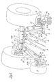
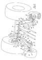
- the wheel axle 16 of each support wheel 15 is enclosed by a hub 17, a receiving flange at its inside, in the area of the support wheels 15 18 is integrally formed, the one in the simplest case pointing in the vertical direction is executed as axially secured bolt 19 pivot axis 20.
- the rim area 21 of the support wheels 15 also passes through the vertical pivot axis 20 through a guide eye 22, the other end attached to the at least one first support arm 23 according to the invention is.
- each support wheel 15 is assigned such a support arm 23, each support arm 23 at its end receiving the respective support wheel 15 from an arbitrarily shaped head piece 24 is formed, the carrier vehicle side an angle profile beam 25 with increasing in the direction of the front axle 14 of the carrier vehicle 1 Cross section is welded.
- the front axle 14 of the agricultural machine 1 are assigned holding flanges 26 on the front, which in the simplest case are axially secured Bolts 27 executed axially 28 are transverse to the direction of travel FR.
- the distance between adjacent retaining flanges 26 is determined by the flange-like extensions 29 penetrates the angle section support 25 in such a way that the respective bolt 27 the angular profile carrier 25 assigned to it pivots in the vertical direction.
- the at least one first support arm 23 of the support frame according to the invention 30 pivotable with the agricultural harvester 1 in the area of Front axle 14 connected.
- the head piece 24 of the first support arm 23 is on the opposite support wheel 15 Formed a retaining tab 31.
- the respective retaining tab 31 takes the front End of the piston rod 32 of a lifting cylinder 33 pointing transversely to the direction of travel FR Axis 34 pivotable on, the cylinder end of the lifting cylinder 33 by one axis 35 also arranged transversely to the direction of travel FR can be pivoted on the receiving device 5 of the agricultural harvester 1 is attached.
- the respective one Lift cylinder 33 the at least one further support arm 36 of the support frame according to the invention 30, the at least one support wheel 15 is pivotable with the receiving device 5 of the agricultural harvester 1 connects.
- the Embodiment two-part support frame 30 is designed in one piece and this one-piece support frame 30 arranged across one or more transverse to the direction of travel FR Swivel axes 28 is arranged pivotably on the agricultural harvesting machine 1. It would also be conceivable that the receiving device 5 via only one lifting cylinder 9 or any number of lifting cylinders 9 supported on the agricultural harvester 1 becomes.
- a particularly powerful design is achieved when the first or the first invention Brackets 23 support wheels 15 in a substantially horizontal direction connect to the agricultural harvester 1 while the second invention Brackets 36 support wheels 15 in a substantially vertical direction connect to the receiving device 5.
- the second support arms 36 as a lifting cylinder 33 are also ensured that the assignment of the support wheels 15 to the receiving device 5 can be changed in the vertical direction, so that the support wheels 15 regardless of the position of the receiving device 5 can always touch the floor 71.
- the lifting cylinder 9 designed in the exemplary embodiment Support arm 36 is designed as a telescopic arm 37 and the movement of each other displaceable profiles 38, 39 of the telescopic arm 37 in the simplest case by means of compression spring 40 is damped, such a compression spring 40 in a manner known per se also in the Lift cylinder 9 can be integrated.
- the vertical pivot axis 20 of the Bolts 19 forming support wheels 15 according to FIG. 3 are gripped on the top by a steering lever 41, one end is assigned a stud 42 pointing in the vertical direction.
- the the respective support wheel 15 receiving support arm 23 has on its the front axle 14 agricultural harvesting machine 1 associated end via a vertical direction pointing stud 43.
- On the stud 43 an angle lever 44 is pivotally movable arranged, which in turn a plurality of stud bolts 45, 46, 47 are assigned non-rotatably.
- a first coupling rod 48 connects the stud 42 of the steering lever 41 so that it can pivot with a stay bolt 45 arranged on the angle lever 44, the coupling rod 48 above and in the area of the angle section support 25 of the respective support arm 23 in Extends towards the front axle 14 of the agricultural harvesting machine 1.
- the neighboring support wheels 15 mirror images of each other arranged steering lever 41, coupling rods 48 and angle lever 44 assigned to the each form a partial steering mechanism 49, 50 for the respective support wheel 15.
- the two partial steering mechanisms 49, 50 via one with the rear ones Stud 46 of the angle lever 44 pivotally connected connecting strut 51st coupled with each other.
- One of the angle levers 44 is connected via a further stud bolt 47
- Steering cylinder 52 assigned to pivot the other end also around a vertical Axis 53 is pivotable from a holding flange 54 fastened to the angle section support 25 is recorded.
- the piston rod 55 can be pushed out of the steering cylinder 52 or moved into it be, the support wheels 15 rectified pivoting movements about their vertical Execute pivot axes 20.
- the agricultural Harvester 1 only one support wheel 15 steerable according to the invention or a plurality of support wheels 15 which can be steered according to the invention or are arranged Several support wheels 15 only part of the support wheels 15 is steerable.
- the steering movement of the steered Axis 57 of the agricultural harvester 1 with its wheels 58 and the steering movement the support wheels 15 according to the invention can be coupled to one another.
- This can be achieved in that the steering wheel 59 arranged on the carrier vehicle 1 a rotation angle sensor 60 is assigned, the output signal of which is in an electronic control unit 61 an output signal for adjusting a directional control valve 62 known per se Depending on the position of the steering wheel 59 generated.
- the directional valve is on the output side 62 line systems 63, 64 assigned, each of the piston-side pressure chambers 65, 66 or the pressure chambers 67, 68 on the piston rod side of the steering cylinder 52, 69 connect with each other so that the wheels 58 of the steered axle 57 of the carrier vehicle 1 and the support wheels 15 according to the invention are steered simultaneously. Due to the Execution of the steering mechanism 49, 50, 51 according to the invention becomes the wheels 58 the steered axle 57 and the steered support wheels 15 deflected in the opposite direction, so that the steered support wheels 15 the steering movement of the agricultural machine 1 support. A particularly good support for the steering movement of the carrier vehicle 1 is achieved when the steering angle ⁇ of the support wheels 15 the inverted Value of the steering angle ⁇ of the wheels 58 of the steered axle 57 of the agricultural Harvester 1 corresponds.
- At least one of the steered impellers 58 of the steering axis 57 of the agricultural harvesting machine 1 is a wheel angle sensor known per se 70, which can be processed in an electronic control unit 61 output signal dependent on the steering angle ⁇ of the impeller 58, which in the electronic control unit 61 in turn generates an output signal which is immediate on the at least one steerable support wheel 15 for deflecting this at least one Support wheel 15 leads to the steering angle ⁇ .
- Support wheels 15 support a minimum load on the floor 71
- the lifting cylinder 9 pivoting the receiving device 5 as a double-acting lifting cylinder 9 so that the lifting cylinder 9 enters the cylinder 11
- Piston rod 8 can be set how high that of the support wheels 15 on the floor 71 load to be supported.
- a traction cylinder 72 may be interposed, which when pressurized the support wheels 15 according to the invention forces on the floor 71, being about the pressurization of the pull cylinder 72 determines the size of the load to be supported is.
- steerable support wheels 15 can also be designed to be actively driven.
Landscapes
- Life Sciences & Earth Sciences (AREA)
- Environmental Sciences (AREA)
- Harvester Elements (AREA)
- Guiding Agricultural Machines (AREA)
- Agricultural Machines (AREA)
Abstract
Description
- Figur 1
- den vorderen Teil einer landwirtschaftliche Erntemaschine in Seitenansicht
- Figur 2
- eine Detailansicht der erfindungsgemäßen Stützradanordnung
- Figur 3
- eine weitere Detailansicht der erfindungsgemäßen Stützradanordnung
- Figur 4
- ein Draufsicht auf die Achsanordnung der landwirtschaftlichen Erntemaschine mit erfindungsgemäßer Stützradanordnung
- 1
- landwirtschaftliche Erntemaschine
- 2
- Mähdrescher
- 3
- Schwenkachse
- 4
- Schrägförderer
- 5
- Aufnahmevorrichtung
- 6
- Halteflansch
- 7
- Achse
- 8
- Kolbenstange
- 9
- Hubzylinder
- 10
- Achse
- 11
- Zylinder
- 12
- Landwirtschaftliches Arbeitsgerät
- 13
- Vorderachse
- 14
- Stützrad
- 15
- Radachse
- 16
- Getreideschneidwerk
- 17
- Nabe
- 18
- Aufnahmeflansch
- 19
- Bolzen
- 20
- Schwenkachse
- 21
- Felgenbereich
- 22
- Führungsöse
- 23
- Tragarm
- 24
- Kopfstück
- 25
- Winkelprofilträger
- 26
- Halteflansch
- 27
- Bolzen
- 28
- Achse
- 29
- Verlängerung
- 30
- Stützrahmen
- 31
- Haltelasche
- 32
- Kolbenstange
- 33
- Hubzylinder
- 34
- Achse
- 35
- Schwenkachse
- 36
- Tragarm
- 37
- Teleskoparm
- 38
- Profil
- 39
- Profil
- 40
- Druckfeder
- 41
- Lenkhebel
- 42
- Stehbolzen
- 43
- Stehbolzen
- 44
- Winkelhebel
- 45
- Stehbolzen
- 46
- Stehbolzen
- 47
- Stehbolzen
- 48
- Koppelstange
- 49
- Teillenkmechanismus
- 50
- Teillenkmechanismus
- 51
- Verbindungsstrebe
- 52
- Lenkzylinder
- 53
- vertikale Schwenkachse
- 54
- Halteflansch
- 55
- Kolbenstange
- 56 57
- Achse
- 58
- Laufräder
- 59
- Lenkrad
- 60
- Drehwinkelsensor
- 61
- elektronische Steuereinheit
- 62
- Wegeventil
- 63
- Leitungssystem
- 64
- Leitungssystem
- 65
- kolbenflächenseitige Druckkammer
- 66
- kolbenflächenseitige Druckkammer
- 67
- kolbenstangenseitige Druckkammer
- 68
- kolbenstangenseitige Druckkammer
- 69
- Lenkzylinder
- 70
- Radwinkelsensor
- 71
- Boden
- 72
- Zugzylinder
- FR
- Fahrtrichtung
- α
- Lenkwinkel
- β
- Lenkwinkel
Claims (21)
- Stützradanordnung für eine landwirtschaftliche Arbeitsmaschine mit wenigstens einer Aufnahmevorrichtung zur Adaption eines landwirtschaftlichen Arbeitsgerätes, wobei der landwirtschaftlichen Erntemaschine in ihrem dem landwirtschaftlichen Arbeitsgerät zugewandten Bereich ein oder mehrere Stützräder zugeordnet sind,
dadurch gekennzeichnet, dass das wenigstens eine Stützrad (15) von einem Stützrahmen (30) aufgenommen wird und der Stützrahmen (30) mit der landwirtschaftlichen Erntemaschine (1, 2) und der Aufnahmevorrichtung (4, 5) in Wirkverbindung steht. - Stützradanordnung für eine landwirtschaftliche Arbeitsmaschine nach Anspruch 1,
dadurch gekennzeichnet, dass der Stützrahmen (30) von einem ersten Tragarm (23) und wenigstens einem weiteren Tragarm (35) gebildet wird, wobei der erste Tragarm (23) mit der landwirtschaftlichen Erntemaschine (1, 2) und der wenigstens eine weitere Tragarm (35) mit der Aufnahmevorrichtung (4, 5) in Wirkverbindung steht. - Stützradanordnung für eine landwirtschaftliche Arbeitsmaschine nach Anspruch 2,
dadurch gekennzeichnet, dass sich der wenigstens eine erste Tragarm (23) im Wesentlichen in horizontaler Richtung erstreckt. - Stützradanordnung für eine landwirtschaftliche Arbeitsmaschine nach Anspruch 2,
dadurch gekennzeichnet, dass sich der wenigstens eine weitere Tragarm (35) im Wesentlichen in vertikaler Richtung erstreckt. - Stützradanordnung für eine landwirtschaftliche Arbeitsmaschine nach einem oder mehreren der vorhergehenden Ansprüche,
dadurch gekennzeichnet, dass die Tragarme (25, 35) schwenkbeweglich mit der landwirtschaftlichen Arbeitsmaschine (1, 2) und der Aufnahmevorrichtung (4, 5) verbunden sind. - Stützradanordnung für eine landwirtschaftliche Arbeitsmaschine nach einem oder mehreren der vorhergehenden Ansprüche,
dadurch gekennzeichnet, dass wenigstens ein Tragarm (25, 35) längenveränderlich ausgeführt ist. - Stützradanordnung für eine landwirtschaftliche Arbeitsmaschine nach Anspruch 6,
dadurch gekennzeichnet, dass der wenigstens eine längenveränderliche Tragarm (35) als Hubzylinder (33) ausgeführt ist. - Stützradanordnung für eine landwirtschaftliche Arbeitsmaschine nach Anspruch 6,
dadurch gekennzeichnet, dass der wenigstens eine längenveränderliche Tragarm (35) als Teleskoparm (36) ausgeführt ist. - Stützradanordnung für eine landwirtschaftliche Arbeitsmaschine nach einem oder mehreren der vorhergehenden Ansprüche,
dadurch gekennzeichnet, dass die Längenänderung des Teleskoparms (36) und/oder des Hubzylinders (33) durch wenigstens ein Dämpfungselement (39) gedämpft wird. - Stützradanordnung für eine landwirtschaftliche Arbeitsmaschine mit wenigstens einer Aufnahmevorrichtung zur Adaption eines landwirtschaftlichen Arbeitsgerätes, wobei der landwirtschaftlichen Erntemaschine in ihrem dem landwirtschaftlichen Arbeitsgerät zugewandten Bereich ein oder mehrere Stützräder zugeordnet sind,
dadurch gekennzeichnet, dass das wenigstens eine Stützrad (15) als lenkbares Stützrad (15) ausgeführt ist. - Stützradanordnung für eine landwirtschaftliche Arbeitsmaschine nach Anspruch 10,
dadurch gekennzeichnet, dass in dem dem landwirtschaftlichen Arbeitsgerät (12, 13) zugewandten Bereich der landwirtschaftlichen Arbeitsmaschine (1, 2) eine Vielzahl von Stützrädern (15) angeordnet sind und wenigstens ein Teil der Stützräder (15) lenkbar sind. - Stützradanordnung für eine landwirtschaftliche Erntemaschine nach einem oder mehreren der vorhergehenden Ansprüche,
dadurch gekennzeichnet, dass wenigstens ein erstes lenkbares Stützrad (15) und ein weiteres lenkbares Stützrad (15) um im Wesentlichen in vertikaler Richtung weisende Schwenkachsen (19, 20) schwenkbar sind, wobei das wenigstens eine erste lenkbare Stützrad (15) und das wenigstens eine weitere lenkbare Stützrad (15) über einen Koppelmechanismus (48, 48, 50) miteinander verbunden sind und von zumindest einem gemeinsamen Lenkzylinder (51) verschwenkt werden. - Stützradanordnung für eine landwirtschaftliche Erntemaschine nach Anspruch 12,
dadurch gekennzeichnet, dass der Koppelmechanismus (48, 49) entlang jedes ein lenkbares Stützrad (15) aufnehmenden Tragarms (35) geführt wird, wobei die entlang der Tragarme (35) geführten Teillenkmechanismen (48, 49) im Bereich der Vorderachse (14) der landwirtschaftlichen Arbeitsmaschine (1, 2) über eine Verbindungsstrebe (50) miteinander verbunden sind. - Stützradanordnung für eine landwirtschaftliche Erntemaschine nach einem oder mehreren der vorhergehenden Ansprüche,
dadurch gekennzeichnet, dass der Teillenkmechanismus (48, 49) von einem die jeweilige Schwenkachse (19, 20) aufnehmenden Lenkhebel (40) gebildet wird, der über zumindest eine Koppelstange (47) gelenkig mit einem Winkelhebel (43) verbunden ist, wobei der Winkelhebel (43) um eine im Wesentlichen vertikale Schwenkachse (42) drehbar an dem wenigstens einen weiteren Tragarm (23) angeordnet ist und die Winkelhebel (43) benachbarter lenkbarer Stützräder (15) über eine Verbindungsstrebe (50) miteinander verbunden sind und an wenigstens einem Winkelhebel (43) der Lenkzylinder (51) des Koppelmechanismus (48, 49, 50) angreift. - Stützradanordnung für eine landwirtschaftliche Erntemaschine nach einem oder mehreren der vorhergehenden Ansprüche,
dadurch gekennzeichnet, dass die Lenkbewegung des wenigstens einen lenkbaren Stützrades (15) an die Lenkbewegung der wenigstens einen Lenkachse (56) der landwirtschaftlichen Erntemaschine (1, 2) gekoppelt ist. - Stützradanordnung für eine landwirtschaftliche Erntemaschine nach Anspruch 15,
dadurch gekennzeichnet, dass die Koppelung der Lenkbewegung durch Koppelung der Lenkzylinder (51, 68) erreicht wird. - Stützradanordnung für eine landwirtschaftliche Erntemaschine nach Anspruch 16,
dadurch gekennzeichnet, dass der Lenkwinkel β zumindest eines Laufrades (57) der Lenkachse (56) der landwirtschaftlichen Erntemaschine (1, 2) bestimmt und der invertierte Wert α dieses Lenkwinkels β selbsttätig an dem wenigstens einen lenkbaren Stützrad (15) eingestellt wird. - Stützradanordnung für eine landwirtschaftliche Erntemaschine nach Anspruch 17,
dadurch gekennzeichnet, dass wenigstens einem Laufrad (57) der Lenkachse (56) der landwirtschaftlichen Erntemaschine (1, 2) ein Radwinkelsensor (69) zugeordnet ist, der ein Radwinkelsignal erzeugt und an eine Steuereinheit (60) übergibt und die Steuereinheit (60) ein Lenkwinkelsignal für das wenigstens eine lenkbare Stützrad (15) generiert und an den Lenkzylinder (51) des wenigstens einen lenkbaren Stützrades (15) überträgt, wobei das Lenkwinkelsignal eine Druckbeaufschlagung oder Druckentlastung des Lenkzylinders (51) bewirkt. - Stützradanordnung für eine landwirtschaftliche Erntemaschine nach einem oder mehreren der vorhergehenden Ansprüche,
dadurch gekennzeichnet, dass die Stützradanordnung (15, 30) demontierbar ist. - Stützradanordnung für eine landwirtschaftliche Erntemaschine nach einem oder mehreren der vorhergehenden Ansprüche,
dadurch gekennzeichnet, dass zwischen Aufnahmevorrichtung (4, 5) und landwirtschaftlicher Erntemaschine (1, 2) ein die landwirtschaftliche Erntemaschine (1, 2) mit der Aufnahmevorrichtung (4, 5) verbindender Zugzylinder (70) zwischengeschaltet ist. - Stützradanordnung für eine landwirtschaftliche Erntemaschine nach einem oder mehreren der vorhergehenden Ansprüche,
dadurch gekennzeichnet, dass das wenigstens eine lenkbare Stützrad (15) aktiv angetrieben ist.
Applications Claiming Priority (2)
| Application Number | Priority Date | Filing Date | Title |
|---|---|---|---|
| DE10130647 | 2001-06-27 | ||
| DE10130647A DE10130647A1 (de) | 2001-06-27 | 2001-06-27 | Stützradanordnung für eine landwirtschaftliche Arbeitsmaschine |
Publications (2)
| Publication Number | Publication Date |
|---|---|
| EP1277392A1 true EP1277392A1 (de) | 2003-01-22 |
| EP1277392B1 EP1277392B1 (de) | 2006-03-29 |
Family
ID=7689416
Family Applications (1)
| Application Number | Title | Priority Date | Filing Date |
|---|---|---|---|
| EP02013050A Expired - Lifetime EP1277392B1 (de) | 2001-06-27 | 2002-06-13 | Stützradanordnung für eine landwirtschaftliche Arbeitsmaschine |
Country Status (8)
| Country | Link |
|---|---|
| US (1) | US6843046B2 (de) |
| EP (1) | EP1277392B1 (de) |
| AR (1) | AR033323A1 (de) |
| AT (1) | ATE321443T1 (de) |
| BR (1) | BR0202420B1 (de) |
| DE (2) | DE10130647A1 (de) |
| HU (1) | HUP0201716A3 (de) |
| RU (1) | RU2297756C2 (de) |
Cited By (2)
| Publication number | Priority date | Publication date | Assignee | Title |
|---|---|---|---|---|
| EP2387870A1 (de) * | 2010-05-21 | 2011-11-23 | CLAAS Selbstfahrende Erntemaschinen GmbH | Landwirtschaftliche Arbeitsmaschine mit Vorsatzgerät |
| US9125343B2 (en) | 2013-11-01 | 2015-09-08 | Cnh Industrial America Llc | Auxiliary axle for an agricultural harvester during road transport |
Families Citing this family (18)
| Publication number | Priority date | Publication date | Assignee | Title |
|---|---|---|---|---|
| DE10240236A1 (de) * | 2002-08-28 | 2004-03-18 | Claas Selbstfahrende Erntemaschinen Gmbh | Stützradanordnung für Fahrzeug |
| DE102006040106A1 (de) * | 2006-08-28 | 2008-03-06 | Claas Selbstfahrende Erntemaschinen Gmbh | Landwirtschaftliches Trägerfahrzeug |
| AT505651B1 (de) * | 2007-11-09 | 2009-03-15 | Schrattenecker Franz Ing | Schneidwerk für einen mähdrescher |
| US7661251B1 (en) * | 2008-08-22 | 2010-02-16 | Deere & Company | Header float system for use with an agricultural windrower or combine |
| DE102008049130A1 (de) * | 2008-09-26 | 2010-04-01 | Claas Selbstfahrende Erntemaschinen Gmbh | Landwirtschaftliche Erntemaschine |
| US8342255B2 (en) * | 2009-10-29 | 2013-01-01 | Cnh America Llc | Steerable agricultural implement with equalized steering effort |
| FI124208B (fi) * | 2010-02-24 | 2014-05-15 | Sandvik Mining & Constr Oy | Louhitun kallioaineksen kuljetukseen soveltuva kuljetuslaite ja sen perävaunu |
| US7971420B1 (en) * | 2010-08-31 | 2011-07-05 | Deere & Company | Draper platform suspension |
| US9944316B2 (en) | 2012-04-24 | 2018-04-17 | Mtd Products Inc | Vehicle drive control systems and the related vehicles |
| US9320197B2 (en) * | 2012-08-17 | 2016-04-26 | Deere & Company | Self-propelled agricultural harvesting machine having a crop attachment which is pivotable about a vertical axis |
| DE102014009158B4 (de) * | 2014-06-25 | 2023-01-26 | Carl Geringhoff Gmbh & Co. Kg | Schneidwerk mit Stützrädern |
| US9781873B2 (en) | 2014-11-19 | 2017-10-10 | Cnh Industrial America Llc | Agricultural implement having power assist carrier wheels |
| US9718507B2 (en) | 2015-10-29 | 2017-08-01 | Cnh Industrial America Llc | Method of steering a weight transfer axle on a combine |
| BE1024333B1 (nl) * | 2016-06-23 | 2018-02-01 | Cnh Industrial Belgium Nv | Maaibordsteun voor een oogstmachine |
| CN106332601B (zh) * | 2016-08-22 | 2018-05-25 | 常城 | 全地形自走式玉米收割机 |
| US10278330B2 (en) * | 2016-10-11 | 2019-05-07 | Deere & Company | Combine feeder house gauge wheels |
| US10779473B2 (en) | 2018-04-18 | 2020-09-22 | Cnh Industrial America Llc | Harvester header support |
| DE102021119897A1 (de) * | 2021-07-30 | 2023-02-02 | Claas Selbstfahrende Erntemaschinen Gmbh | Landwirtschaftliche Maschine mit schwingungsgedämpftem Vorsatzgerät |
Citations (8)
| Publication number | Priority date | Publication date | Assignee | Title |
|---|---|---|---|---|
| DE1457948A1 (de) * | 1964-04-21 | 1969-04-03 | Claas Dipl Ing Reinhold | Frontschneidender Maehdrescher |
| DE1482255A1 (de) * | 1964-09-09 | 1969-10-16 | Fritz Jost | Dreschverfahren |
| DE2101710A1 (de) * | 1971-01-15 | 1972-07-20 | Schmitt, Helwig, 3523 Grebenstein | Eine an einer Zugmaschine frontangekuppelte Erntemaschine |
| DE2140368A1 (de) * | 1964-04-21 | 1973-02-15 | Claas Maschf Gmbh Geb | Frontschneidender maehdrescher |
| US3822534A (en) * | 1973-01-09 | 1974-07-09 | Gehl Co | Front mounted harvester |
| US4203275A (en) * | 1978-08-04 | 1980-05-20 | Vermeer Gary J | Tractor mounted harvester unit |
| US5794423A (en) * | 1996-11-01 | 1998-08-18 | Bob Mcleod Inc. | Mobile harvester for chaff, grain, grain leavings and weed seeds |
| DE19918551A1 (de) | 1999-04-23 | 2000-10-26 | Deere & Co | Erntemaschine |
Family Cites Families (33)
| Publication number | Priority date | Publication date | Assignee | Title |
|---|---|---|---|---|
| US1093473A (en) * | 1913-09-11 | 1914-04-14 | Edwin A Reeves | Vacuum-cleaner. |
| US2606417A (en) * | 1948-01-03 | 1952-08-12 | Ferguson Harry Inc | Reversible implement and coupling therefor |
| US2788988A (en) * | 1952-09-17 | 1957-04-16 | Sperry Rand Corp | Trailer implement frame construction for tractor drawn and powered implements |
| US2727347A (en) * | 1952-11-07 | 1955-12-20 | Int Harvester Co | Combined hay crusher and tedder |
| DE1108972B (de) * | 1958-11-05 | 1961-06-15 | Lilla Harrie Redskapsverkst Ab | Vorrichtung zur gleichzeitigen Lenkung von Schlepper und Arbeitsgeraet |
| US3349549A (en) * | 1964-02-12 | 1967-10-31 | Texas Industries Inc | Harvesters |
| US3387436A (en) * | 1965-04-13 | 1968-06-11 | Int Harvester Co | Rotary cutter |
| NL137376C (de) * | 1967-11-01 | |||
| DE2053815A1 (de) * | 1970-11-02 | 1972-05-10 | Robert Bosch Gmbh, 7000 Stuttgart | Hydraulische Hubeinrichtung an Mähdreschern |
| SU495224A1 (ru) * | 1972-11-09 | 1975-12-15 | Стерлитамакский Завод "Авангард" | Рулевое управление четырехколесного транспортного средства со всеми управл емыми колесами |
| DE2261558C3 (de) * | 1972-12-15 | 1982-07-08 | Maschinenfabrik Fahr Ag Gottmadingen, 7702 Gottmadingen | Elektrohydraulische Steuerung für die Höhenverstellung des Mähtisches eines Mähdreschers oder einer vergleichbaren Erntemaschine |
| US3878959A (en) * | 1973-01-08 | 1975-04-22 | Hesston Corp | Stack mover |
| SU490418A1 (ru) * | 1973-03-30 | 1975-11-05 | Азербайджанский Научно-Исследовательский Институт Механизации И Электрофикации Сельского Хозяйства | Приспособление к сельскохоз йственным машинам |
| SU499166A1 (ru) * | 1974-05-17 | 1976-01-15 | Липецкий Ордена Ленина Тракторный Завод Имени Ххш Съезда Кпсс | Система рулевого управлени транспортного средства со всеми управл емыми колесами |
| GB1543324A (en) * | 1975-05-02 | 1979-04-04 | Clayson Nv | Resilient mounting of attachment for agricultural machinery |
| US3995411A (en) * | 1975-05-16 | 1976-12-07 | Owatonna Manufacturing Company, Inc. | Oscillating mounting support for agricultural instrument |
| US4141200A (en) * | 1976-10-27 | 1979-02-27 | Johnson Farm Machinery Co., Inc. | Automatic header adjustment for harvesters |
| IT1107807B (it) * | 1978-03-07 | 1985-12-02 | Laverda Spa Pietro | Macchina falcia condizionatrice |
| US4206582A (en) * | 1979-02-12 | 1980-06-10 | International Harvester Company | Header lift arrangement for windrowers |
| US4250696A (en) * | 1979-04-03 | 1981-02-17 | Hash Jack J | Brush and mesquite cutter |
| US4257732A (en) * | 1979-07-20 | 1981-03-24 | Leroy Staffanson | Hay stacker |
| SU998147A1 (ru) * | 1980-11-17 | 1983-02-23 | Уральский лесотехнический институт им.Ленинского комсомола | Система автоматического регулировани характеристики подвески транспортного средства |
| SU943063A1 (ru) * | 1980-12-09 | 1982-07-15 | Военная Ордена Ленина Краснознаменная Академия Бронетанковых Войск Им.Маршала Советского Союза Малиновского Р.Я. | Система рулевого управлени транспортного средства с передними и задними управл емыми колесами |
| US4473993A (en) * | 1983-05-26 | 1984-10-02 | Sperry Corporation | Cutting angle adjustment mechanism for crop harvesting machines |
| SU1140702A1 (ru) * | 1983-11-15 | 1985-02-23 | Ярославский Ордена Ленина И Ордена Октябрьской Революции Моторный Завод | Сельскохоз йственный уборочный агрегат |
| WO1987000393A1 (en) * | 1984-02-03 | 1987-01-29 | Rippelton N.V. | Apparatus for a harvesting machine |
| SU1222220A1 (ru) * | 1984-10-04 | 1986-04-07 | Украинский научно-исследовательский институт сельскохозяйственного машиностроения | Самоходна сельскохоз йственна машина |
| US4768525A (en) * | 1987-08-31 | 1988-09-06 | J. I. Case Company | Stone ejection door mechanism for harvesting equipment |
| US5005342A (en) * | 1990-02-13 | 1991-04-09 | Ezra C. Lundahl, Inc. | Crop processor |
| RU2021670C1 (ru) * | 1991-09-23 | 1994-10-30 | Владимир Филиппович Власенко | Механизм навески жатки на самоходную молотилку |
| US5201167A (en) * | 1992-01-29 | 1993-04-13 | Rowse Dan D | Multiple implement frame with parallel mounting bars |
| JP3192065B2 (ja) * | 1995-08-31 | 2001-07-23 | 株式会社クボタ | フロントマウント型乗用芝刈り機 |
| US6415873B1 (en) * | 2000-10-19 | 2002-07-09 | Jimmy Hudgins | Sand fighter |
-
2001
- 2001-06-27 DE DE10130647A patent/DE10130647A1/de not_active Withdrawn
-
2002
- 2002-05-03 AR ARP020101643A patent/AR033323A1/es active IP Right Grant
- 2002-05-22 HU HU0201716A patent/HUP0201716A3/hu unknown
- 2002-06-13 EP EP02013050A patent/EP1277392B1/de not_active Expired - Lifetime
- 2002-06-13 DE DE50206193T patent/DE50206193D1/de not_active Expired - Lifetime
- 2002-06-13 AT AT02013050T patent/ATE321443T1/de not_active IP Right Cessation
- 2002-06-26 BR BRPI0202420-9A patent/BR0202420B1/pt not_active IP Right Cessation
- 2002-06-27 US US10/184,342 patent/US6843046B2/en not_active Expired - Fee Related
- 2002-06-27 RU RU2002117009/11A patent/RU2297756C2/ru not_active IP Right Cessation
Patent Citations (8)
| Publication number | Priority date | Publication date | Assignee | Title |
|---|---|---|---|---|
| DE1457948A1 (de) * | 1964-04-21 | 1969-04-03 | Claas Dipl Ing Reinhold | Frontschneidender Maehdrescher |
| DE2140368A1 (de) * | 1964-04-21 | 1973-02-15 | Claas Maschf Gmbh Geb | Frontschneidender maehdrescher |
| DE1482255A1 (de) * | 1964-09-09 | 1969-10-16 | Fritz Jost | Dreschverfahren |
| DE2101710A1 (de) * | 1971-01-15 | 1972-07-20 | Schmitt, Helwig, 3523 Grebenstein | Eine an einer Zugmaschine frontangekuppelte Erntemaschine |
| US3822534A (en) * | 1973-01-09 | 1974-07-09 | Gehl Co | Front mounted harvester |
| US4203275A (en) * | 1978-08-04 | 1980-05-20 | Vermeer Gary J | Tractor mounted harvester unit |
| US5794423A (en) * | 1996-11-01 | 1998-08-18 | Bob Mcleod Inc. | Mobile harvester for chaff, grain, grain leavings and weed seeds |
| DE19918551A1 (de) | 1999-04-23 | 2000-10-26 | Deere & Co | Erntemaschine |
Cited By (3)
| Publication number | Priority date | Publication date | Assignee | Title |
|---|---|---|---|---|
| EP2387870A1 (de) * | 2010-05-21 | 2011-11-23 | CLAAS Selbstfahrende Erntemaschinen GmbH | Landwirtschaftliche Arbeitsmaschine mit Vorsatzgerät |
| RU2549104C2 (ru) * | 2010-05-21 | 2015-04-20 | КЛААС Зельбстфаренде Эрнтемашинен ГмбХ | Рабочая сельхозмашина со сменным аппаратом |
| US9125343B2 (en) | 2013-11-01 | 2015-09-08 | Cnh Industrial America Llc | Auxiliary axle for an agricultural harvester during road transport |
Also Published As
| Publication number | Publication date |
|---|---|
| DE10130647A1 (de) | 2003-01-16 |
| US20030019197A1 (en) | 2003-01-30 |
| DE50206193D1 (de) | 2006-05-18 |
| BR0202420B1 (pt) | 2009-05-05 |
| ATE321443T1 (de) | 2006-04-15 |
| US6843046B2 (en) | 2005-01-18 |
| BR0202420A (pt) | 2003-04-29 |
| RU2297756C2 (ru) | 2007-04-27 |
| HU0201716D0 (de) | 2002-07-29 |
| HUP0201716A2 (hu) | 2002-11-28 |
| EP1277392B1 (de) | 2006-03-29 |
| AR033323A1 (es) | 2003-12-10 |
| RU2002117009A (ru) | 2004-01-20 |
| HUP0201716A3 (en) | 2003-11-28 |
Similar Documents
| Publication | Publication Date | Title |
|---|---|---|
| EP1269825B1 (de) | Stützradanordnung für eine landwirtschaftliche Arbeitsmaschine | |
| EP1277392B1 (de) | Stützradanordnung für eine landwirtschaftliche Arbeitsmaschine | |
| DE19639777C2 (de) | Landwirtschaftliches Fahrzeug | |
| EP2192026B2 (de) | Landwirtschaftliche Zugmaschine | |
| DE102007046890A1 (de) | Anbauvorrichtung für ein Arbeitsfahrzeug | |
| EP1048195B1 (de) | Schwenkeinrichtung für Stützräder | |
| EP1611781B1 (de) | Stützradmechanismus an einem Vorsatzgerät | |
| EP2269847B1 (de) | Fahrzeug mit pendelbeweglicher Achse | |
| DE19919959A1 (de) | Fahrwerkanordnung | |
| EP1277393B1 (de) | Stützradanordnung für eine landwirtschaftliche Arbeitsmaschine | |
| DE102013111426B4 (de) | Zusatzgerät für ein landwirtschaftliches Fahrzeug und landwirtschaftliches Fahrzeug | |
| DE102018118908A1 (de) | Landwirtschaftliche Arbeitsmaschine | |
| DE69100896T2 (de) | Fahrzeug. | |
| EP0503396B1 (de) | Heuwerbungsmaschine | |
| DE10240236A1 (de) | Stützradanordnung für Fahrzeug | |
| EP1394021B1 (de) | Stützradanordnung für Fahrzeug | |
| EP3461660B1 (de) | Mähdrescher | |
| EP4074156A1 (de) | Deichselanordnung für eine gezogene landmaschine | |
| EP1175819B1 (de) | Landwirtschaftliche Arbeitsmaschine | |
| EP3971066B1 (de) | Traktor mit raupenlaufwerk | |
| EP4124221B1 (de) | Landwirtschaftliche maschine und landwirtschaftliche maschinenkombination | |
| DE19702888A1 (de) | Heumaschine | |
| EP1763981B1 (de) | Vorrichtung zum Führen eines Arbeitsgerätes | |
| EP1782674B1 (de) | Mähmaschine | |
| DE10024031A1 (de) | Selbstfahrende Hackfruchterntemaschine |
Legal Events
| Date | Code | Title | Description |
|---|---|---|---|
| PUAI | Public reference made under article 153(3) epc to a published international application that has entered the european phase |
Free format text: ORIGINAL CODE: 0009012 |
|
| AK | Designated contracting states |
Kind code of ref document: A1 Designated state(s): AT BE CH CY DE DK ES FI FR GB GR IE IT LI LU MC NL PT SE TR |
|
| AX | Request for extension of the european patent |
Free format text: AL;LT;LV;MK;RO;SI |
|
| 17P | Request for examination filed |
Effective date: 20030722 |
|
| AKX | Designation fees paid |
Designated state(s): AT BE CH CY DE DK ES FI FR GB GR IE IT LI LU MC NL PT SE TR |
|
| 17Q | First examination report despatched |
Effective date: 20050314 |
|
| GRAP | Despatch of communication of intention to grant a patent |
Free format text: ORIGINAL CODE: EPIDOSNIGR1 |
|
| GRAS | Grant fee paid |
Free format text: ORIGINAL CODE: EPIDOSNIGR3 |
|
| GRAA | (expected) grant |
Free format text: ORIGINAL CODE: 0009210 |
|
| AK | Designated contracting states |
Kind code of ref document: B1 Designated state(s): AT BE CH CY DE DK ES FI FR GB GR IE IT LI LU MC NL PT SE TR |
|
| PG25 | Lapsed in a contracting state [announced via postgrant information from national office to epo] |
Ref country code: IT Free format text: LAPSE BECAUSE OF FAILURE TO SUBMIT A TRANSLATION OF THE DESCRIPTION OR TO PAY THE FEE WITHIN THE PRESCRIBED TIME-LIMIT;WARNING: LAPSES OF ITALIAN PATENTS WITH EFFECTIVE DATE BEFORE 2007 MAY HAVE OCCURRED AT ANY TIME BEFORE 2007. THE CORRECT EFFECTIVE DATE MAY BE DIFFERENT FROM THE ONE RECORDED. Effective date: 20060329 Ref country code: GB Free format text: LAPSE BECAUSE OF FAILURE TO SUBMIT A TRANSLATION OF THE DESCRIPTION OR TO PAY THE FEE WITHIN THE PRESCRIBED TIME-LIMIT Effective date: 20060329 Ref country code: IE Free format text: LAPSE BECAUSE OF FAILURE TO SUBMIT A TRANSLATION OF THE DESCRIPTION OR TO PAY THE FEE WITHIN THE PRESCRIBED TIME-LIMIT Effective date: 20060329 Ref country code: NL Free format text: LAPSE BECAUSE OF FAILURE TO SUBMIT A TRANSLATION OF THE DESCRIPTION OR TO PAY THE FEE WITHIN THE PRESCRIBED TIME-LIMIT Effective date: 20060329 |
|
| REG | Reference to a national code |
Ref country code: GB Ref legal event code: FG4D Free format text: NOT ENGLISH |
|
| REG | Reference to a national code |
Ref country code: CH Ref legal event code: EP |
|
| REG | Reference to a national code |
Ref country code: IE Ref legal event code: FG4D Free format text: LANGUAGE OF EP DOCUMENT: GERMAN |
|
| REF | Corresponds to: |
Ref document number: 50206193 Country of ref document: DE Date of ref document: 20060518 Kind code of ref document: P |
|
| PG25 | Lapsed in a contracting state [announced via postgrant information from national office to epo] |
Ref country code: SE Free format text: LAPSE BECAUSE OF FAILURE TO SUBMIT A TRANSLATION OF THE DESCRIPTION OR TO PAY THE FEE WITHIN THE PRESCRIBED TIME-LIMIT Effective date: 20060629 Ref country code: DK Free format text: LAPSE BECAUSE OF FAILURE TO SUBMIT A TRANSLATION OF THE DESCRIPTION OR TO PAY THE FEE WITHIN THE PRESCRIBED TIME-LIMIT Effective date: 20060629 |
|
| PG25 | Lapsed in a contracting state [announced via postgrant information from national office to epo] |
Ref country code: LI Free format text: LAPSE BECAUSE OF NON-PAYMENT OF DUE FEES Effective date: 20060630 Ref country code: MC Free format text: LAPSE BECAUSE OF NON-PAYMENT OF DUE FEES Effective date: 20060630 Ref country code: CH Free format text: LAPSE BECAUSE OF NON-PAYMENT OF DUE FEES Effective date: 20060630 |
|
| PG25 | Lapsed in a contracting state [announced via postgrant information from national office to epo] |
Ref country code: ES Free format text: LAPSE BECAUSE OF FAILURE TO SUBMIT A TRANSLATION OF THE DESCRIPTION OR TO PAY THE FEE WITHIN THE PRESCRIBED TIME-LIMIT Effective date: 20060710 |
|
| PG25 | Lapsed in a contracting state [announced via postgrant information from national office to epo] |
Ref country code: PT Free format text: LAPSE BECAUSE OF FAILURE TO SUBMIT A TRANSLATION OF THE DESCRIPTION OR TO PAY THE FEE WITHIN THE PRESCRIBED TIME-LIMIT Effective date: 20060829 |
|
| NLV1 | Nl: lapsed or annulled due to failure to fulfill the requirements of art. 29p and 29m of the patents act | ||
| ET | Fr: translation filed | ||
| GBV | Gb: ep patent (uk) treated as always having been void in accordance with gb section 77(7)/1977 [no translation filed] |
Effective date: 20060329 |
|
| REG | Reference to a national code |
Ref country code: IE Ref legal event code: FD4D |
|
| PLBE | No opposition filed within time limit |
Free format text: ORIGINAL CODE: 0009261 |
|
| STAA | Information on the status of an ep patent application or granted ep patent |
Free format text: STATUS: NO OPPOSITION FILED WITHIN TIME LIMIT |
|
| REG | Reference to a national code |
Ref country code: CH Ref legal event code: PL |
|
| 26N | No opposition filed |
Effective date: 20070102 |
|
| PG25 | Lapsed in a contracting state [announced via postgrant information from national office to epo] |
Ref country code: AT Free format text: LAPSE BECAUSE OF NON-PAYMENT OF DUE FEES Effective date: 20060613 |
|
| PG25 | Lapsed in a contracting state [announced via postgrant information from national office to epo] |
Ref country code: GR Free format text: LAPSE BECAUSE OF FAILURE TO SUBMIT A TRANSLATION OF THE DESCRIPTION OR TO PAY THE FEE WITHIN THE PRESCRIBED TIME-LIMIT Effective date: 20060630 |
|
| PG25 | Lapsed in a contracting state [announced via postgrant information from national office to epo] |
Ref country code: FI Free format text: LAPSE BECAUSE OF FAILURE TO SUBMIT A TRANSLATION OF THE DESCRIPTION OR TO PAY THE FEE WITHIN THE PRESCRIBED TIME-LIMIT Effective date: 20060329 |
|
| PG25 | Lapsed in a contracting state [announced via postgrant information from national office to epo] |
Ref country code: LU Free format text: LAPSE BECAUSE OF NON-PAYMENT OF DUE FEES Effective date: 20060613 Ref country code: TR Free format text: LAPSE BECAUSE OF FAILURE TO SUBMIT A TRANSLATION OF THE DESCRIPTION OR TO PAY THE FEE WITHIN THE PRESCRIBED TIME-LIMIT Effective date: 20060329 |
|
| PG25 | Lapsed in a contracting state [announced via postgrant information from national office to epo] |
Ref country code: CY Free format text: LAPSE BECAUSE OF FAILURE TO SUBMIT A TRANSLATION OF THE DESCRIPTION OR TO PAY THE FEE WITHIN THE PRESCRIBED TIME-LIMIT Effective date: 20060329 |
|
| REG | Reference to a national code |
Ref country code: FR Ref legal event code: PLFP Year of fee payment: 15 |
|
| PGFP | Annual fee paid to national office [announced via postgrant information from national office to epo] |
Ref country code: FR Payment date: 20160627 Year of fee payment: 15 |
|
| REG | Reference to a national code |
Ref country code: DE Ref legal event code: R084 Ref document number: 50206193 Country of ref document: DE |
|
| PGFP | Annual fee paid to national office [announced via postgrant information from national office to epo] |
Ref country code: DE Payment date: 20170420 Year of fee payment: 16 |
|
| PGFP | Annual fee paid to national office [announced via postgrant information from national office to epo] |
Ref country code: BE Payment date: 20170620 Year of fee payment: 16 |
|
| REG | Reference to a national code |
Ref country code: FR Ref legal event code: ST Effective date: 20180228 |
|
| PG25 | Lapsed in a contracting state [announced via postgrant information from national office to epo] |
Ref country code: FR Free format text: LAPSE BECAUSE OF NON-PAYMENT OF DUE FEES Effective date: 20170630 |
|
| REG | Reference to a national code |
Ref country code: DE Ref legal event code: R119 Ref document number: 50206193 Country of ref document: DE |
|
| REG | Reference to a national code |
Ref country code: BE Ref legal event code: MM Effective date: 20180630 |
|
| PG25 | Lapsed in a contracting state [announced via postgrant information from national office to epo] |
Ref country code: DE Free format text: LAPSE BECAUSE OF NON-PAYMENT OF DUE FEES Effective date: 20190101 |
|
| PG25 | Lapsed in a contracting state [announced via postgrant information from national office to epo] |
Ref country code: BE Free format text: LAPSE BECAUSE OF NON-PAYMENT OF DUE FEES Effective date: 20180630 |