EP1276352A2 - EL-Steuerschaltung, Steuerverfahren und elektronisches Gerät - Google Patents
EL-Steuerschaltung, Steuerverfahren und elektronisches Gerät Download PDFInfo
- Publication number
- EP1276352A2 EP1276352A2 EP02254510A EP02254510A EP1276352A2 EP 1276352 A2 EP1276352 A2 EP 1276352A2 EP 02254510 A EP02254510 A EP 02254510A EP 02254510 A EP02254510 A EP 02254510A EP 1276352 A2 EP1276352 A2 EP 1276352A2
- Authority
- EP
- European Patent Office
- Prior art keywords
- circuit
- voltage
- turning
- switching
- signal
- Prior art date
- Legal status (The legal status is an assumption and is not a legal conclusion. Google has not performed a legal analysis and makes no representation as to the accuracy of the status listed.)
- Withdrawn
Links
Images


Classifications
-
- H—ELECTRICITY
- H05—ELECTRIC TECHNIQUES NOT OTHERWISE PROVIDED FOR
- H05B—ELECTRIC HEATING; ELECTRIC LIGHT SOURCES NOT OTHERWISE PROVIDED FOR; CIRCUIT ARRANGEMENTS FOR ELECTRIC LIGHT SOURCES, IN GENERAL
- H05B44/00—Circuit arrangements for operating electroluminescent light sources
-
- Y—GENERAL TAGGING OF NEW TECHNOLOGICAL DEVELOPMENTS; GENERAL TAGGING OF CROSS-SECTIONAL TECHNOLOGIES SPANNING OVER SEVERAL SECTIONS OF THE IPC; TECHNICAL SUBJECTS COVERED BY FORMER USPC CROSS-REFERENCE ART COLLECTIONS [XRACs] AND DIGESTS
- Y02—TECHNOLOGIES OR APPLICATIONS FOR MITIGATION OR ADAPTATION AGAINST CLIMATE CHANGE
- Y02B—CLIMATE CHANGE MITIGATION TECHNOLOGIES RELATED TO BUILDINGS, e.g. HOUSING, HOUSE APPLIANCES OR RELATED END-USER APPLICATIONS
- Y02B20/00—Energy efficient lighting technologies, e.g. halogen lamps or gas discharge lamps
- Y02B20/30—Semiconductor lamps, e.g. solid state lamps [SSL] light emitting diodes [LED] or organic LED [OLED]
Definitions
- the present invention relates to an EL driving circuit, a control method and an apparatus more particularly to those having an electroluminescent element.
- Fig.6 is a circuit diagram of a conventional EL driving circuit.
- the EL driving circuit is arranged that an IC chip 40 applies voltage, which is supplied through a coil L and a resister R3 by a control signal Hon from a microcomputer to be not shown, to an EL element 50 to drive (Refer to U.S. Patent No. 4,527,096).
- main circuits such as an oscillating circuit OSC, flip-flops FF1 and FF2 as a dividing circuit and a switched H-bridge circuit are provided.
- Terminals (PAD) of PIN 1 to 8 connecting to each circuit are also provided in the IC chip 40.
- the oscillating circuit OSC is connected to a capacitor C3 through the PIN 7 and PIN8, and connected to the flip-flop FF1 in the IC chip 40.
- the oscillating circuit OSC generates a high frequency clock and outputs the clock to the flip-flop FF1.
- the flip-flop FF1 outputs its output to the flip-flop FF2 and one of input terminals of an AND circuit 1 described below (hereinafter referred to as "AND1").
- the flip-flop FF2 generates a low frequency clock of which the clock outputted from the flip-flop FF1 is divided by 16.
- the flip-flopFF2 outputs its output, as two low frequency clocks in reversal phase each other to output them to one of input terminals of an AND circuit 2 described below (hereinafter referred to as "AND2”) and one of input terminals of an AND circuit 3 described below (hereinafter referred to as "AND3”) respectively.
- the switched H-bridge circuit is constituted by main elements such as ANDs 1, 2 and 3, transistors Tr1, 2 and 3, diodes 1 to 4 and thyristors SCR1 and 2, and those elements are connected as described below.
- Each one of input terminals of the ANDs 1, 2 and 3 is connected to the PIN1 respectively.
- the control signal Hon is connected to the PIN1.
- the PING is a power supply terminal Vdd of the IC chip 40 and connected to a positive electrode Vdd of a power supply such as a battery and the like.
- the PIN2 is a power supply terminal GND of the IC chip 40 and connected to a negative electrode of the power supply such as the battery and the like.
- the PIN2 and PING are connected to Vdd and GND in an inner circuit of the IC to supply electric power respectively.
- a capacitor C2 is located outside the IC and connected to the PIN2 and PIN6 to operate as an electrolytic compensating capacitor.
- Wiring between the other input terminals of ANDs 1,2, and 3 and the PIN1 is connected to a pull-down resister R1 connected to the GND.
- An output of the AND1 is connected to a base of the transistor Tr1 through a capacitor C1 and a resistor R2 which are connected in parallel.
- An output of the AND2 is connected to a base of the transistor Tr2, and an output of the AND3 is connected to a base of the transistor Tr3.
- a collector of the transistor Tr1 is connected to the PIN3. Between the PIN3 and the positive electrode Vdd of the power supply, the voltage set-up coil outside the IC is connected, strictly the resister R3 and the coil L are connected in series. Anodes of the diodes D1 and D3 are connected to wiring between the transistor Tr1 and the PIN3.
- a cathode of the diode D1 is connected to an anode of the thyristor SCR1.
- An gate of the thyristor SCR1 is connected to a collector of the transistor Tr2.
- a cathode of the thyristor SCR1 is connected to the PIN4 and an anode of the diode D2.
- a cathode of the diode D2, like the gate of the thyristor SCR1, is connected to the collector of the transistor Tr2.
- a cathode of the diode D3 is connected to an anode of the thyristor SCR2.
- a gate of the thyristor SCR2 is connected to a collector side of the transistor Tr3.
- a cathode of the thyristor SCR2 is connected to the PINS and an anode of the diode D4.
- a cathode of the diode D4, like the gate of the thyristor SCR2, is connected to the collector of the transistor Tr3.
- Emitters of the transistors Tr1, Tr2 and Tr3 are connected to the GND respectively.
- the PIN4 and PIN5 are connected to a capacitor C4 which is an equivalent circuit of the EL element 50.
- the transistor Tr1 performs switching operation responsive to the clock.
- the transistor Tr1 applies pulsating voltage to the diodes D1 and D3 through the coil L and the resister R3 by the switching operation.
- polarity of voltage applied to the capacitor C4 is switched alternately and the voltage is continuously supplied to the capacitor C4, which permits high voltage to be supplied to the EL element 50.
- Fig.7 is a timing chart of an EL driving circuit.
- the timing chart shows timing of relationship between voltage and time.
- the timing chart shows appearance that, in case that the clock (CLOCK) outputted from the oscillating circuit OSC to the flip-flop FF1 is supplied to the switched H-bridge circuit, responsive to the clock from the flip-flop FF2 not to be shown in Fig.7, voltage (EL1) of the PINS and voltage (EL2) of the PIN4 are alternately set-upped to be supplied to the capacitor C4.
- the microcomputer switches the signal Hon from a high state to a low state at the timing (duration X shown in Fig.7) when the polarity of the voltage applied to the capacitor of the EL device is reversed, which causes the transistor (Tr1) to be turned off, thus creating the counter electromotive force Vcoil1 in the PIN3.
- a problem is that, when the Vcoil1 exceeds a rating Vces of the transistor (Tr1), the transistor (Tr1) to be turned off turns on, which causes noise such as power supply fluctuation and the like to be created.
- the noise is created from the coil as electromagnetic wave
- the microcomputer is sometimes reset by error due to the electromagnetic wave, consequently there exerts a problem that the noise causes operation of the microcomputer to be unstable.
- the noise causes operation of the microcomputer to be unstable.
- the microcomputer includes time function, time is reset by the noise to become 00:00.
- the Vces is a characteristic of collector to emitter maximum voltage in a transistor and represented by a characteristic curve between collector current Ic and collector-emitter voltage Vce.
- Fig.8 is a timing chart in case that the rating Vces of the transistor (Tr1) is higher than the design value.
- Fig.9 is a timing chart in case that the rating Vces of the transistor (Tr1) is lower than the design value.
- an EL driving circuit comprises an EL element, a voltage set-up coil which generates pulsating voltage for turning on the EL element, an oscillating circuit for generating a reference signal, a dividing circuit for dividing a clock generated by the oscillating circuit into at least two kinds of frequency clocks, a first switching circuit for switching current through the voltage set-up coil by the higher frequency clock of the two kinds of frequency clocks divided by the dividing circuit, a second switching circuit for switching polarity of voltage applied to the EL element by the lower frequency clock of the two kinds of frequency clocks divided by the dividing circuit, a control circuit for switching connection between the dividing circuit and the first switching circuit, and connection between the dividing circuit and the second switching circuit at the same time by a control signal which turns on and off the EL element, and a suppressing circuit for suppressing counter electromotive force created in case of turning off the EL element lower than the withstanding voltage of the first switching circuit.
- the suppressing circuit enables the counter electromotive force generated in case of turning off the EL element to be lower than the withstanding voltage of the first switching circuit.
- the EL element may be made of either inorganic EL materials or organic EL materials.
- the suppressing circuit includes a first delay circuit constituted by a combination of a resistor and a capacitor, and the first delay circuit is arranged at a forestep of the control circuit, in case that the control signal turning off the EL element is inputted to the first delay circuit, input voltage of the first delay circuit is switched from a high state to an open state.
- Another EL driving circuit is that the suppressing circuit includes a resistor connected in parallel to the voltage set-up coil and suppresses the counter electromotive force in case of turning off the EL element.
- the suppressing circuit includes a second delay circuit constituted by a combination of a resistor, a capacitor and a third switching circuit, and in the second delay circuit, the third switching circuit turns on in case of turning off the EL element.
- a third switching element for switching the capacitor is provided, the switching element is turned on in case of turning off the EL element and electric charge is charged by voltage applied to a gate of a third switching transistor.
- Another EL driving circuit is that a signal generating circuit for generating a signal which controls turning on and off the EL element is provided, and the signal generating circuit generates the control signal which turns on and off the EL element.
- a control method comprises steps of generating a control signal which changes a high state to an open state for turning off the EL element, inputting the control signal to a delay circuit and decreasing the voltage of the delay circuit from the high state according to a time constant, generating an irregular pulse by the control circuit when the decreasing voltage of the delay circuit reaches to certain a voltage to threshold voltage of the control circuit, and releasing energy stored in a voltage set-up coil by a first switching element which turns on or off current through the voltage set-up coil responsive to the irregular pulse.
- the control circuit when the control signal is inputted to the delay circuit, the voltage of the delay circuit decreases from the high state according to the time constant and reaches a certain voltage for the threshold voltage of the control circuit, then the control circuit generates the irregular pulse and the first switching element turns on or off current flowing through the voltage set-up coil, which permits energy stored in the voltage set-up coil to release.
- the time constant of the delay circuit is not lower than 10 microseconds and not more than 1 millisecond.
- a control method comprises steps of generating a control signal which changes a high state to an open state for turning off the EL element, starting delay operation by turning on a switch of the delay circuit when the control signal is inputted to the delay circuit, outputting a low signal to the delay circuit by the control circuit when the control signal is inputted to the control circuit, outputting a signal decreased according to the time constant of the delay circuit when the low signal is inputted to the delay circuit, and decreasing current through the voltage set-up coil responsive to the signal by the first switching circuit when the signal is inputted to the first switching circuit.
- the invention also relates to an electronic apparatus that comprises a power supply and the EL driving circuit driven by electric power from the power supply.
- the electronic apparatus includes a timepiece, a display, an electronic calculator, a mobile phone, an audio hardware, a computer of handheld type, a PDA (Personal Digital Assistance), and so on.
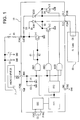
- Fig.1 is a circuit diagram of an EL driving circuit of Example 1 for carrying out the invention.
- the EL driving circuit is arranged that an IC chip 10 applies voltage supplied through a coil L and a resister R3 by a control signal Hon from a microcomputer 7, which generates a signal for controlling to turn on and off an EL device, to the EL element 50 to drive.
- a control signal Hon from a microcomputer 7, which generates a signal for controlling to turn on and off an EL device, to the EL element 50 to drive.
- the same numerical labels and signs are indicated to explain in the same case as the conventional configuration.
- main circuits such as an oscillating circuit OSC, flip-flop FF1 and FF2 as a dividing circuit and switched H-bridge circuit are provided.
- the IC chip 10 is provided with terminals (PAD) PINs 1 to 8 connected to each circuit.
- the oscillating circuit OSC is connected to a capacitor C3 through the PIN7 and PIN8 and connected to the flip-flop FF1 inside the IC chip 10.
- the oscillating circuit OSC generates a high frequency clock and outputs the clock to flip-flop FF1.
- the flip-flop FF1 outputs its output to the flip-flop FF2 and one of input terminals of an AND circuit 1 described below (hereinafter referred to as "AND1").
- the flip-flop FF2 divides the clock outputted from the flip-flop FF1 by 16 to generate a lower frequency clock.
- the flip-flop FF2 makes the two low frequency clocks in reversal phase each other to output them to one of input terminals of an AND circuit 2 described below (hereinafter referred to as "AND2”) and one of input terminals of an AND circuit 3 described below (hereinafter referred to as "AND3”) respectively.
- the switched H-bridge circuit is constituted by main elements such as ANDs 1, 2 and 3, transistors Tr1, Tr2 and Tr3, diodes D1 to D4 and thyristors SCR1 and SCR2, and those elements are connected as described below.
- PIN1 is connected to the control signal Hon from the microcomputer 7.
- the PING is a power supply terminal Vdd of the IC chip 10 and connected to a positive electrode Vdd of a power supply such as a battery and the like.
- the PIN2 is a power supply terminal GND of the IC chip 10 and connected to a negative electrode of the power supply such as the battery and the like.
- the PIN2 and PIN6 are connected to Vdd and GND in an inner circuit of the IC to supply electric power respectively.
- the capacitor C2 is located outside the IC and connected to the PIN2 and PING to operate as an electrolytic compensating capacitor.
- Wiring between the other input terminals of ANDs 1,2, and 3 and the PIN1 is connected to a resister R1 and a capacitor C5, which are connected in parallel and constitute a delay circuit, connected to the GND.
- the resistor R1 and the capacitor C5 relaxes response of voltage of the signal Hon inputted from the PIN1 in case of turning off the EL element.
- an output of the AND1 is connected to a base of the transistor Tr1 through a capacitor C1 and a resistor R2.
- the capacitor C1 and the resistor R2 are connected in parallel.
- An output of the AND2 is connected to a base of the transistor Tr2, and an output of the AND3 is connected to a base of the transistor Tr3.
- a collector of the transistor Tr1 is connected to the PIN3.
- the resister R3 and the coil L are connected in series between the PIN3 and the positive electrode Vdd of the power supply outside the IC.
- Anodes of the diodes D1 and D3 are connected to wiring between the transistor Tr1 and the PIN3.
- a cathode of the diode D1 is connected to an anode of the thyristor SCR1.
- An gate of the thyristor SCR1 is connected to a collector of the transistor Tr2.
- a cathode of the thyristor SCR1 is connected to the PIN4 and an anode of the diode D2.
- a cathode of the diode D2, like the gate of the thyristor SCR1, is connected to the collector of the transistor Tr2.
- a cathode of the diode D3 is connected to an anode of the thyristor SCR2.
- a gate of the thyristor SCR2 is connected to a collector side of the transistor Tr3.
- a cathode of the thyristor SCR2 is connected to the PINS and an anode of the diode D4.
- a cathode of the diode D4, like the gate of the thyristor SCR2, is connected to the collector of the transistor Tr3.
- Emitters of the transistors Tr1, Tr2 and Tr3 are connected to the GND respectively.
- PIN4 and PIN5 are connected to a capacitor C4 which is a equivalent circuit of the EL element 50.
- the signal Hon is switched a low state to a high state by the microcomputer 7.
- the signal is inputted to one of inputs of ANDs 1, 2 and 3 through the PIN1 respectively.
- certain electric charge is charged in the capacitor C5. Operation of steps from turning on the EL light is omitted because there is little difference from the conventional case.
- the microcomputer 7 deenergizes voltage of the signal Hon supplied from the PIN1 and at the same time the electric charge stored in the capacitor C5 is discharged through the resistor R1, which causes reduction of the voltage of the signal Hon to become gentle.
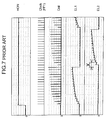
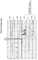
- Fig.2 and Fig.3 are timing charts of the EL driving circuit of Example 1 for carrying out the invention.
- the timing charts show the timing of a relationship between voltage and time.
- the timing charts show appearance in a case that the signal Hon inputted from the PIN1 to the IC chip 10 is switched from a high state to an open state.
- the voltage of the signal Hon descends gently like a curve ⁇ with little fluctuation by the resistor R3 and the capacitor C5.
- the AND1 chatters to output an irregular pulse.
- the transistor Tr1 responsive to the irregular pulse performs switching to release energy stored in the coil. After that, when the signal Hon becomes a low state, the AND1 outputs low and the transistor Tr1 turns off completely.
- Example 1 for carrying out the invention creation of the counter electromotive force above the rating Vces, which is generated in the same case of turning off the EL device as the conventional case, can be suppressed. This permits voltage of the PIN3 to be suppressed below the rating Vces. As a result, error of the microcomputer can be prevented.
- the time constant ⁇ is about 40 microseconds in examples of Fig.2 and Fig.3, a lower limit of the time constant based on experiments is 1 microsecond.
- the lower limit of the time constant ô is 10 or more microseconds. It is sufficient that a higher limit of the time constant ô is 1 or less millisecond, in consideration of penetration current during relaxation of the signal Hon, error by electrostatic noise from outside and so on.
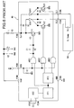
- Fig.4 is a circuit diagram of an EL driving circuit of Example 2 for carrying out the invention.
- the EL driving circuit is arranged that an IC chip 20 applies voltage supplied through a coil L and a resister R3 by a control signal Hon from a microcomputer 7, which generates a signal for controlling to turn on and off an EL device, to the EL element 50 to drive.
- a control signal Hon from a microcomputer 7, which generates a signal for controlling to turn on and off an EL device, to the EL element 50 to drive.
- the same numerical labels and signs are indicated to explain in the same case as the conventional configuration or Example 1 for carrying out the invention.
- main circuits such as an oscillating circuit OSC, flip-flops FF1 and FF2 as a dividing circuit and a switched H-bridge circuit are provided.
- the IC chip 20 is provided with terminals (PAD) of PINs 1 to 8 connected to each circuit.
- the oscillating circuit OSC is connected to a capacitor C3 through the PIN7 and PIN8 and connected to the flip-flop FF1 inside the IC chip 20.
- the oscillating circuit OSC generates a high frequency clock and outputs the clock to the flip-flop FF1.
- the flip-flop FF1 outputs its output to the flip-flop FF2 and one of input terminals of an AND circuit 1 described below (hereinafter referred to as "AND1").
- the flip-flop FF2 generates a lower frequency clock compared with the higher frequency clock inputted to an input terminal of the AND1.
- the flip-flop FF2 makes the two low frequency clocks in reversal phase each other to output them to one of input terminals of an AND circuit 2 described below (hereinafter referred to as "AND2”) and one of input terminals of an AND circuit 3 described below (hereinafter referred to as "AND3”) respectively.
- the switched H-bridge circuit is constituted by main elements such as ANDs 1, 2 and 3, transistors Tr1, Tr2 and Tr3, diodes D1 to D4 and thyristors SCR1 and SCR2, and those elements are connected as described below.
- One of input terminals of ANDs 1, 2 and 3 are connected to the PIN1 respectively.
- the control signal Hon from the microcomputer 7 is connected to the PIN1.
- the PIN6 is a power supply terminal Vdd of the IC chip 20 and connected to a positive electrode Vdd of a power supply such as a battery and the like.
- the PIN2 is a power supply terminal GND of the IC chip 20 and connected to a negative electrode of the power supply such as the battery and the like. And the PIN2 and PIN6 are connected Vdd and GND in an inner circuit of the IC to supply electric power respectively.
- the capacitor C2 is connected to the PIN2 and PIN6 outside the IC to operate as an electrolytic compensating capacitor. Wiring between the other input terminals of ANDs 1,2, and 3 and the PIN1 is connected to a pull-down resister R1 connected to the GND.
- an output terminal of the AND1 is connected to a base of the transistor Tr1 through a capacitor C1 and a resistor R2.
- the capacitor C1 and the resistor R2 are connected in parallel.
- An output terminal of the AND2 is connected to a base of the transistor Tr2, and an output terminal of the AND3 is connected to a base of the transistor Tr3.
- a collector side of the transistor Tr1 is connected to the PIN3.
- the resister R3 and the coil L are connected in series, and a resister R4 and them are connected in parallel outside the IC. That is to say, the resistor R4 is connected to both ends of the series-connected coil L and resistor R3.
- Anodes of the diodes D1 and D3 are connected to wiring between the transistor Tr1 and the PIN3.
- the resistor R4 forms a closed circuit with the coil L and the resistor R3. This causes pulsating voltage of the coil L to be consumed as Joule heat by the resistors R4 and R3. As a result, the electromagnetic wave created from the coil L can be reduced.
- a cathode of the diode D1 is connected to an anode of the thyristor SCR1.
- a gate of the thyristor SCR1 is connected to a collector of the transistor Tr2.
- a cathode of the thyristor SCR1 is connected to the PIN4 and an anode of the diode D2.
- a cathode of the diode D2, like the gate of the thyristor SCR1, is connected to the collector of the transistor Tr2.
- a cathode of the diode D3 is connected to an anode of the thyristor SCR2.
- a gate of the thyristor SCR2 is connected to a collector side of the transistor Tr3.
- a cathode of the thyristor SCR2 is connected to the PINS and an anode of the diode D4.
- a cathode of the diode D4, like the gate of the thyristor SCR2, is connected to the collector of the transistor Tr3.
- Emitter sides of the transistors Tr1 Tr2 and Tr3 are connected to the GND respectively.
- the PIN4 and PINS are connected to a capacitor C4 which is a equivalent circuit of the EL element 50.
- the microcomputer 7 switches the signal Hon from a high state to a low state to turn off the transistor Tr1.
- This causes the resistor R4 to form the closed circuit with the coil L and the resistor R3, which permits pulsating voltage of the coil L to be consumed as Joule heat by the resistors R4 and R3.
- the electromagnetic wave created from the coil L can be reduced.
- Example 2 even in a period of time when voltage generated in case of turning off the EL element is higher than the rating Vces, energy of the counter electromotive force generated by the coil L can be absorbed. As a result, error of the microcomputer can be prevented.
- Fig.5 is a circuit diagram of an EL driving circuit of Example 3 for carrying out the invention.
- the EL driving circuit is arranged that an IC chip 30 applies voltage supplied through a coil L and a resister R3 by a control signal Hon from a microcomputer 7, which generates a signal for controlling to turn on and off an EL device, to the EL element 50 to drive.
- a control signal Hon from a microcomputer 7, which generates a signal for controlling to turn on and off an EL device, to the EL element 50 to drive.
- the same numerical labels and signs are indicated to explain in the same case as the conventional configuration or Examples 1 and 2.
- main circuits such as an oscillating circuit OSC, flip-flops FF1 and FF2 as a dividing circuit and a switched H-bridge circuit are provided.
- the IC chip 30 is provided with terminals (PAD) of PINs 1 to 8 connected to each circuit.
- the oscillating circuit OSC is connected to a capacitor C3 through the PIN 7 and PIN8 and connected to the flip-flop FF1 inside the IC.
- the oscillating circuit OSC generates a higher frequency clock and outputs the clock to the flip-flop FF1.
- the flip-flop FF1 outputs its output to the flip-flop FF2 and one of input terminals of an AND circuit 1 described below (hereinafter referred to as "AND1").
- the flip-flop FF2 generates a lower frequency clock compared with the higher frequency clock inputted to an input terminal of the AND1.
- the flip-flop FF2 makes the two low frequency clocks in reversal phase each other to output them to one of input terminals of an AND circuit 2 described below (hereinafter referred to as "AND2”) and one of input terminals of an AND circuit 3 described below (hereinafter referred to as "AND3”) respectively.
- the switched H-bridge circuit is constituted by main elements such as ANDs 1, 2 and 3, transistors Tr1, Tr2 and Tr3, diodes D1 to D4 and thyristors SCR1 and SCR2, and those elements are connected as described below.
- the other input terminals of the ANDs 1, 2 and 3 are connected to the PIN1 respectively.
- the control signal Hon from the microcomputer 7 is connected to the PIN1.
- the PIN6 is a power supply terminal Vdd of the IC chip 30 and connected to a positive electrode Vdd of a power supply such as a battery and the like.
- the PIN2 is a power supply terminal GND of the IC chip 30 and connected to a negative electrode of the power supply such as the battery and the like. And the PIN2 and PIN6 are connected Vdd and GND in an inner circuit of the IC to supply electric power respectively.
- a capacitor C2 is located outside the IC and connected to the PIN2 and PIN6 to operate as an electrolytic compensating capacitor.
- Wiring between the other input terminals of ANDs 1,2, and 3 and the PIN1 is connected to a pull-down resister R1 connected to the GND.
- an output of the AND1 is connected to a base of the transistor Tr1 through a capacitor C1 and a resistor R2.
- the capacitor C1 and the resistor R2 are connected in parallel.
- the base of the transistor Tr1 is connected to one of electrodes of a capacitor C6.
- the other electrode of the capacitor C6 is connected to a drain of a transistor Tr4.
- a gate terminal of the transistor Tr4 is connected to wiring between inputs of ANDs 1 to 3 and the PIN1.
- a source of the transistor Tr4 is connected to the power supply terminal Vdd (PIN6).
- An output of the AND2 is connected to a base of the transistor Tr2, and an output of the AND3 is connected to a base of the transistor Tr3.
- a collector side of the transistor Tr1 is connected to the PIN3. Between the PIN3 and the positive electrode Vdd of the power supply, the resister R3 and the coil L are connected in series outside the IC. Anodes of the diodes D1 and D3 are connected to wiring between the transistor Tr1 and the PIN3.
- a cathode of the diode D1 is connected to an anode of the thyristor SCR1.
- a gate of the thyristor SCR1 is connected to a collector of the transistor Tr2.
- a cathode of the thyristor SCR1 is connected to the PIN4 and an anode of the diode D2.
- a cathode of the diode D2, like the gate of the thyristor SCR1, is connected to the collector of the transistor Tr2.
- a cathode of the diode D3 is connected to an anode of the thyristor SCR2.
- a gate of the thyristor SCR2 is connected to a collector side of the transistor Tr3.
- a cathode of the thyristor SCR2 is connected to the PIN5 and an anode terminal of the diode D4.
- a cathode of the diode D4, like the gate of the thyristor SCR2, is connected to the collector of the transistor Tr3.
- Each emitter of the transistors Tr1, Tr2 and Tr3 is connected to the GND respectively.
- the PIN4 and PIN5 are connected to a capacitor C4 which is a equivalent circuit of the EL element 50.
- a microcomputer 7 switches the signal Hon from a high state to a low state, which causes a gate voltage of the transistor Tr4 to become from H to L to turn on the transistor Tr4. And when an output of AND1 becomes low, charging current flows to the capacitor C6. This allows voltage drop applied to the base of the transistor Tr1 to become gentle. As a result, collector current, that is to say, change of current flowing to the coil L becomes small.
- Example 3 for carrying out the invention, because the change of current flowing to the coil L becomes small even in the same period of time as the conventional case that voltage generated in case of turning off the EL light is higher than the rating Vces, voltage of the coil L can be suppressed below the rating Vces. As a result, error of the microcomputer can be prevented.
- Transistors which perform the same switching operation as each transistor explained in each of the above Examples may be usable with sorts such as npn type, pnp type and the like.
- the EL element is an EL element
- the EL element can be applied to not only an element but also an EL display apparatus which displays characters, image and so on.
- an EL driving circuit which suppresses counter electromotive force of a coil generated by rapid voltage fluctuation in case of turning off an EL element, eliminates creation of noise from the coil, and in turn prevents error of a microcomputer due to the noise.
Landscapes
- Physics & Mathematics (AREA)
- Engineering & Computer Science (AREA)
- Microelectronics & Electronic Packaging (AREA)
- Optics & Photonics (AREA)
- Control Of El Displays (AREA)
- Electroluminescent Light Sources (AREA)
- Control Of Indicators Other Than Cathode Ray Tubes (AREA)
Applications Claiming Priority (4)
| Application Number | Priority Date | Filing Date | Title |
|---|---|---|---|
| JP2001206049 | 2001-07-06 | ||
| JP2001206049 | 2001-07-06 | ||
| JP2002101310A JP4080775B2 (ja) | 2001-07-06 | 2002-04-03 | El駆動回路、el駆動回路の制御方法及び電子機器 |
| JP2002101310 | 2002-04-03 |
Publications (2)
| Publication Number | Publication Date |
|---|---|
| EP1276352A2 true EP1276352A2 (de) | 2003-01-15 |
| EP1276352A3 EP1276352A3 (de) | 2004-01-07 |
Family
ID=26618272
Family Applications (1)
| Application Number | Title | Priority Date | Filing Date |
|---|---|---|---|
| EP02254510A Withdrawn EP1276352A3 (de) | 2001-07-06 | 2002-06-27 | EL-Steuerschaltung, Steuerverfahren und elektronisches Gerät |
Country Status (4)
| Country | Link |
|---|---|
| US (1) | US6674243B2 (de) |
| EP (1) | EP1276352A3 (de) |
| JP (1) | JP4080775B2 (de) |
| CN (1) | CN1396577A (de) |
Families Citing this family (8)
| Publication number | Priority date | Publication date | Assignee | Title |
|---|---|---|---|---|
| GB2372647B (en) * | 2001-02-26 | 2005-06-29 | Cambridge Consultants | Electronic circuits |
| JP2004246320A (ja) * | 2003-01-20 | 2004-09-02 | Sanyo Electric Co Ltd | アクティブマトリクス駆動型表示装置 |
| JP3989399B2 (ja) * | 2003-05-01 | 2007-10-10 | ローム株式会社 | 半導体集積回路装置 |
| CN2636576Y (zh) * | 2003-06-19 | 2004-08-25 | 悦诚贸易(国际)有限公司 | 冷光片驱动装置 |
| JP2005310854A (ja) | 2004-04-19 | 2005-11-04 | Sanyo Electric Co Ltd | 駆動回路 |
| FR2874777B1 (fr) * | 2004-09-02 | 2007-01-05 | Sagem | Telephone mobile et procede d'utilisation de ce telephone mobile |
| CN103208252B (zh) * | 2012-01-11 | 2017-05-24 | 深圳富泰宏精密工业有限公司 | 显示屏发光二极管控制电路 |
| CN107733318B (zh) * | 2017-09-06 | 2020-10-09 | 深圳市道通智能航空技术有限公司 | 一种电机发音方法、装置、电子调速器和无人飞行器 |
Family Cites Families (6)
| Publication number | Priority date | Publication date | Assignee | Title |
|---|---|---|---|---|
| US3670960A (en) * | 1970-09-14 | 1972-06-20 | Robertshaw Controls Co | Control apparatus |
| JPH02143297A (ja) * | 1988-11-25 | 1990-06-01 | Alps Electric Co Ltd | El表示素子の駆動回路 |
| JPH0765952A (ja) * | 1993-08-31 | 1995-03-10 | Nec Kansai Ltd | 分散型el素子の駆動回路 |
| US5559402A (en) * | 1994-08-24 | 1996-09-24 | Hewlett-Packard Company | Power circuit with energy recovery for driving an electroluminescent device |
| US6072477A (en) * | 1996-07-10 | 2000-06-06 | Matsushita Electric Industrial Co., Ltd. | El display and driving circuit for the same |
| US6204609B1 (en) * | 2000-01-13 | 2001-03-20 | Durel Corporation | Enhanced inverter for powering an EL lamp |
-
2002
- 2002-04-03 JP JP2002101310A patent/JP4080775B2/ja not_active Expired - Fee Related
- 2002-06-27 EP EP02254510A patent/EP1276352A3/de not_active Withdrawn
- 2002-07-02 US US10/187,563 patent/US6674243B2/en not_active Expired - Fee Related
- 2002-07-05 CN CN02126174A patent/CN1396577A/zh active Pending
Also Published As
| Publication number | Publication date |
|---|---|
| EP1276352A3 (de) | 2004-01-07 |
| US6674243B2 (en) | 2004-01-06 |
| CN1396577A (zh) | 2003-02-12 |
| JP4080775B2 (ja) | 2008-04-23 |
| US20030071575A1 (en) | 2003-04-17 |
| JP2003086364A (ja) | 2003-03-20 |
Similar Documents
| Publication | Publication Date | Title |
|---|---|---|
| US6650169B2 (en) | Gate driver apparatus having an energy recovering circuit | |
| US5982105A (en) | Transformerless electroluminescent lamp driver topology | |
| US5313141A (en) | Three terminal inverter for electroluminescent lamps | |
| JP3878393B2 (ja) | 容量性負荷特性を示すエレクトロルミネセントランプを駆動する直流−交流切換回路 | |
| JPH07154962A (ja) | 定電圧発生回路 | |
| JP2001338756A (ja) | 容量性負荷の駆動回路および容量性負荷の駆動用集積回路 | |
| EP1300054B1 (de) | El-treiber mit lampenentladungs-überwachungsvorrichtung | |
| EP1276352A2 (de) | EL-Steuerschaltung, Steuerverfahren und elektronisches Gerät | |
| US5418434A (en) | Voltage-boosting circuit for an electroluminescent lamp driver | |
| US20020041478A1 (en) | Circuit for driving a solenoid | |
| US6462485B1 (en) | EL driver for small semiconductor die | |
| US6597123B1 (en) | Inverter for driving EL lamp and liquid crystal display | |
| US6369513B1 (en) | Vehicle lamp lighting-driving apparatus | |
| US6693387B2 (en) | Electroluminescent driver circuit | |
| US6091164A (en) | Single inverter with dual boost | |
| JP2009219017A (ja) | 負荷制御装置、及びその入力パルスの生成方法 | |
| JP4406969B2 (ja) | El表示装置 | |
| CN1659929B (zh) | 具有灯放电检测的场致发光灯驱动电路及便携式装置 | |
| KR20010087004A (ko) | 저전력 스캔 구동 회로를 가지는 표시(display) 소자 | |
| WO2005116964A1 (en) | Driving electroluminescent displays | |
| US20100194284A1 (en) | Circuit arrangement for operating a converter | |
| JP2001083933A (ja) | 容量性表示パネル駆動装置 | |
| JP2002313560A (ja) | El表示装置 | |
| JPH0544154B2 (de) | ||
| JPH06265655A (ja) | 駆動回路及び電子機器 |
Legal Events
| Date | Code | Title | Description |
|---|---|---|---|
| PUAI | Public reference made under article 153(3) epc to a published international application that has entered the european phase |
Free format text: ORIGINAL CODE: 0009012 |
|
| AK | Designated contracting states |
Kind code of ref document: A2 Designated state(s): AT BE CH CY DE DK ES FI FR GB GR IE IT LI LU MC NL PT SE TR |
|
| AX | Request for extension of the european patent |
Free format text: AL;LT;LV;MK;RO;SI |
|
| PUAL | Search report despatched |
Free format text: ORIGINAL CODE: 0009013 |
|
| AK | Designated contracting states |
Kind code of ref document: A3 Designated state(s): AT BE CH CY DE DK ES FI FR GB GR IE IT LI LU MC NL PT SE TR |
|
| AX | Request for extension of the european patent |
Extension state: AL LT LV MK RO SI |
|
| AKX | Designation fees paid | ||
| REG | Reference to a national code |
Ref country code: DE Ref legal event code: 8566 |
|
| STAA | Information on the status of an ep patent application or granted ep patent |
Free format text: STATUS: THE APPLICATION IS DEEMED TO BE WITHDRAWN |
|
| 18D | Application deemed to be withdrawn |
Effective date: 20040708 |