EP1275448A2 - Anordnung zum Abdichten eines Endabschnitts eines rohrförmigen Werkstücks in einem Werkzeug zum Innenhochdruckumformen - Google Patents
Anordnung zum Abdichten eines Endabschnitts eines rohrförmigen Werkstücks in einem Werkzeug zum Innenhochdruckumformen Download PDFInfo
- Publication number
- EP1275448A2 EP1275448A2 EP02013671A EP02013671A EP1275448A2 EP 1275448 A2 EP1275448 A2 EP 1275448A2 EP 02013671 A EP02013671 A EP 02013671A EP 02013671 A EP02013671 A EP 02013671A EP 1275448 A2 EP1275448 A2 EP 1275448A2
- Authority
- EP
- European Patent Office
- Prior art keywords
- pressure
- workpiece
- sealing
- piston
- pressure chamber
- Prior art date
- Legal status (The legal status is an assumption and is not a legal conclusion. Google has not performed a legal analysis and makes no representation as to the accuracy of the status listed.)
- Withdrawn
Links
- 238000007789 sealing Methods 0.000 title claims abstract description 32
- 230000000903 blocking effect Effects 0.000 claims abstract description 3
- 238000000034 method Methods 0.000 description 6
- 230000006835 compression Effects 0.000 description 4
- 238000007906 compression Methods 0.000 description 4
- 230000015572 biosynthetic process Effects 0.000 description 1
- 238000007493 shaping process Methods 0.000 description 1
- 238000009966 trimming Methods 0.000 description 1
Images
Classifications
-
- B—PERFORMING OPERATIONS; TRANSPORTING
- B21—MECHANICAL METAL-WORKING WITHOUT ESSENTIALLY REMOVING MATERIAL; PUNCHING METAL
- B21D—WORKING OR PROCESSING OF SHEET METAL OR METAL TUBES, RODS OR PROFILES WITHOUT ESSENTIALLY REMOVING MATERIAL; PUNCHING METAL
- B21D26/00—Shaping without cutting otherwise than using rigid devices or tools or yieldable or resilient pads, i.e. applying fluid pressure or magnetic forces
- B21D26/02—Shaping without cutting otherwise than using rigid devices or tools or yieldable or resilient pads, i.e. applying fluid pressure or magnetic forces by applying fluid pressure
- B21D26/033—Deforming tubular bodies
- B21D26/045—Closing or sealing means
Definitions
- hydraulic high pressure medium usually over at least one end section introduced into the interior of the workpiece.
- sealing mandrels take place by means of hydraulic cylinders axially in the end sections of the workpiece or in the form of a bell over the end sections and seal the interior, especially with the help of sealing rings.
- the hydraulic cylinders and closed valves act here for the subsequent shaping of the workpiece Counter pressure.
- the sealing pins can also be used on the front of the workpiece e.g. a serrated ring seal, a stepped seal or a cone seal be pressed.
- sealing mandrels form a sealing cone (Wedge member seal).
- the object of the invention is based on the prior art based on an arrangement for sealing an end portion of a tubular Workpiece in a tool for hydroforming create that is simpler, has fewer parts and at which significantly reduces the cycle times for a forming process can.
- the essence of the invention is the difference in the effective piston area of the Pressure piston in the pressure chamber to the inner cross-sectional area in the end section of the workpiece.
- the pressure chamber is removed from the pressure source from a hydraulic high pressure medium. Since the pressure channel connecting the pressure chamber to the interior of the workpiece in the pressure piston due to the locking in the direction of the pressure chamber Check valve is closed, the pressure in the pressure chamber increases. This causes the plunger to move toward the end portion of the workpiece moves until the sealing mandrel contacts the workpiece and its Seals interior. By increasing pressure in the pressure chamber the closing force of the check valve is then overcome. The Check valve opens so that the internal pressure builds up in the workpiece and the workpiece is formed.
- the arrangement can be on only one end of a tool or on both Ends are provided.
- the seals the components of the pressure plunger forming sealing mandrels and the No additional material tracking when forming the workpiece Hydraulic units or complex controls are necessary are.
- the traversing movements of the sealing mandrels are determined by the same Pressure source causes the internal pressure for the actual one Internal high pressure forming process originates.
- the sealing or the application of a counterforce only from this pressure source. Reduce the processing times of a hydroforming operation noticeable because the sealing mandrels immediately when the internal pressure rises be relocated and create a seal.
- the arrangement according to the invention is therefore particularly suitable for hydroforming using mechanical presses.
- the hydroforming process takes place in the Pressure build-up in a very short time.
- a flat design for a seal to the end face of the workpiece is sufficient to the necessary internal pressure for the expansion of the workpiece.
- Due to the flat design can also be achieved that an expansion directly in the area of Contact area between the end face of the sealing mandrel and the end face of the workpiece becomes possible. This allows the workpiece to be placed directly in the sealing area are brought to the final contour, a subsequent end trimming is avoided.
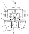
- the tool 4 has two configurations that are relatively movable relative to one another of the workpiece 3 determining dies 5 and 6.
- the lower die is with 5 and the upper die is designated with 6.
- the face of the workpiece 3 to be formed is in a stationary housing 7, a pressure chamber 8 is formed, which is connected via a feed line 9 a pressure source 10 for a hydraulic high pressure medium is connected.
- a pressure piston 11 is sealingly guided in the pressure chamber 8.
- the pressure piston 11 has a stepped axial pressure channel 12, which the Pressure chamber 8 connects to the interior 13 of the workpiece 3.
- Pressure channel 12 is a check valve blocking in the direction of the pressure chamber 8 14 arranged.
- the check valve 14 is composed of a conical valve seat 15, a spherical sealing body 16, one Helical compression spring 17 and a longitudinally channeled screw 18 together, which is screwed into a threaded section 19 of the pressure channel 12.
- a sealing mandrel 20 is connected, which at Embodiment with the annular end face 21 of the workpiece 3 seals a flat end face 22.
- the housing 7 and the pressure piston 11 is connected via restoring elements 23 in the form of helical tension springs.
- restoring elements 23 endeavor to push the pressure piston 11 into the Withdraw starting position.
- the tool 4 is opened and the workpiece 3 to be formed in the lower die 5 placed. Then by lowering the upper die 6 the tool 4 closed. Following this, the Pressure chamber 8 from the pressure source 10 with hydraulic high pressure medium applied. Since the check valve 14 the pressure channel 12 in Locks pressure piston 11, the pressure in the pressure chamber 8. This increases Pressure now moves the pressure piston 11 in the direction of the Workpiece 3 until the end face 22 of the sealing piston 20 on the end face 21 of the workpiece 3 strikes and brings about a seal.
- the pressure chamber 8 of the Pressure source 10 separately.
- the pressure drops to zero, causing the reset elements 23 Guide the pressure piston 11 back to the starting position.
- the check valve 14 closes the pressure channel 12 in the pressure piston 11.
- the tool 4 with respect to the lower die 5 and upper die 6 opened and the formed workpiece 3 can be removed.
Landscapes
- Physics & Mathematics (AREA)
- Fluid Mechanics (AREA)
- Engineering & Computer Science (AREA)
- Mechanical Engineering (AREA)
- Shaping Metal By Deep-Drawing, Or The Like (AREA)
Abstract
Description
- 1 -
- Anordnung
- 2 -
- Endabschnitte v. 3
- 3 -
- Werkstück
- 4 -
- Werkzeug
- 5 -
- Untergesenk v. 4
- 6 -
- Obergesenk v. 4
- 7 -
- Gehäuse
- 8 -
- Druckkammer in 7
- 9 -
- Zuleitung
- 10 -
- Druckquelle
- 11 -
- Druckkolben
- 12 -
- Druckkanal in 11
- 13 -
- Innenraum v. 3
- 14 -
- Rückschlagventil
- 15 -
- Ventilsitz
- 16 -
- Dichtkörper
- 17 -
- Schraubendruckfeder
- 18 -
- Schraube
- 19 -
- Gewindeabschnitt v. 12
- 20 -
- Abdichtdorn
- 21 -
- Stirnseite v. 3
- 22 -
- Stirnfläche v. 20
- 23 -
- Rückstellelemente
- 24 -
- Ausleger an 7
- 25 -
- Ausleger an 11
- KF -
- Kolbenfläche v. 11
- QF -
- Querschnittsfläche v. 13
Claims (2)
- Anordnung zum Abdichten eines Endabschnitts (2) eines rohrförmigen Werkstücks (3) in einem Werkzeug (4) zum Innenhochdruckumformen, welche einen mit dem Endabschnitt (2) zusammenwirkenden Abdichtdorn (20) als zumindest mittelbaren Bestandteil eines Druckkolbens (11) umfasst, der in einer an eine Druckquelle (10) für ein hydraulisches Hochdruckmedium anschließbaren Druckkammer (8) zwangsgeführt ist und in einem die Druckkammer (8) mit dem Innenraum (13) des Werkstücks (3) verbindenden axialen Druckkanal (12) ein in Richtung zur Druckkammer (8) sperrendes Rückschlagventil (14) aufweist, wobei die wirksame Kolbenfläche (KF) des Druckkolbens (11) in der Druckkammer (8) größer als die Querschnittsfläche (QF) im Innenraum (13) des Endabschnitts (2) des Werkstücks (3) bemessen ist.
- Anordnung nach Patentanspruch 1, bei welcher der Druckkolben (11) bei von der Druckquelle (10) getrennter Druckkammer (8) durch eine mechanische, elektrische, pneumatische oder hydraulische Rückstellkraft (23) in die Ausgangsposition zurückführbar ist.
Applications Claiming Priority (2)
| Application Number | Priority Date | Filing Date | Title |
|---|---|---|---|
| DE10134321 | 2001-07-14 | ||
| DE10134321A DE10134321C1 (de) | 2001-07-14 | 2001-07-14 | Anordnung zum Abdichten eines Endabschnitts eines rohrförmigen Werkstücks in einem Werkzeug zum Innenhochdruckumformen |
Publications (2)
| Publication Number | Publication Date |
|---|---|
| EP1275448A2 true EP1275448A2 (de) | 2003-01-15 |
| EP1275448A3 EP1275448A3 (de) | 2004-01-02 |
Family
ID=7691816
Family Applications (1)
| Application Number | Title | Priority Date | Filing Date |
|---|---|---|---|
| EP02013671A Withdrawn EP1275448A3 (de) | 2001-07-14 | 2002-07-01 | Anordnung zum Abdichten eines Endabschnitts eines rohrförmigen Werkstücks in einem Werkzeug zum Innenhochdruckumformen |
Country Status (3)
| Country | Link |
|---|---|
| US (1) | US6804979B2 (de) |
| EP (1) | EP1275448A3 (de) |
| DE (1) | DE10134321C1 (de) |
Families Citing this family (7)
| Publication number | Priority date | Publication date | Assignee | Title |
|---|---|---|---|---|
| DE102007019511B3 (de) * | 2007-04-25 | 2008-11-13 | Benteler Automobiltechnik Gmbh | Vorrichtung und Verfahren zum Innenhochdruckumformen eines Verbundmetallrohres |
| DE102009030632C5 (de) | 2009-06-25 | 2014-12-31 | Benteler Automobiltechnik Gmbh | Verfahren und Vorrichtung zur Herstellung eines Katalysators |
| US8136378B2 (en) * | 2009-09-21 | 2012-03-20 | Ford Global Technologies, Llc | Seal for fluid forming tools |
| US20120047979A1 (en) * | 2010-08-25 | 2012-03-01 | Schuler Inc. | Hydroforming die assembly and method for deforming a tube |
| DE102011051965A1 (de) | 2011-07-20 | 2013-01-24 | Benteler Automobiltechnik Gmbh | Verfahren zur Herstellung eines rohrförmigen Strukturbauteils für ein Kraftfahrzeug und Strukturbauteil |
| JP5799907B2 (ja) * | 2012-07-13 | 2015-10-28 | トヨタ自動車株式会社 | 漏れ検査装置 |
| US8910500B2 (en) | 2012-09-10 | 2014-12-16 | National Research Council Of Canada | Low friction end feeding in tube hydroforming |
Citations (1)
| Publication number | Priority date | Publication date | Assignee | Title |
|---|---|---|---|---|
| EP0873802A1 (de) * | 1997-04-25 | 1998-10-28 | Sumitomo Metal Industries, Ltd. | Verfahren und Vorrichtung zum Hydroformen eines Rohres |
Family Cites Families (7)
| Publication number | Priority date | Publication date | Assignee | Title |
|---|---|---|---|---|
| US453410A (en) * | 1891-06-02 | langerfeld | ||
| US701549A (en) * | 1902-01-11 | 1902-06-03 | Standard Oil Co | Apparatus for shaping metal receptacles. |
| GB544466A (en) * | 1940-01-25 | 1942-04-14 | Clifford Mfg Co | Improvements in or relating to apparatus for deforming thin wall tubular shells |
| SU1176994A1 (ru) * | 1984-04-23 | 1985-09-07 | Ленинградский Ордена Ленина Политехнический Институт Им.М.И.Калинина | Устройство дл гидроштамповки полых деталей |
| DE4017072A1 (de) * | 1990-05-26 | 1991-11-28 | Benteler Werke Ag | Verfahren zum hydraulischen umformen eines rohrfoermigen hohlkoerpers und vorrichtung zur durchfuehrung des verfahrens |
| US5819573A (en) * | 1997-06-17 | 1998-10-13 | Seaman; Roy C. | Hydraulic forming of workpieces from sheet metal |
| ES2209372T3 (es) * | 1998-10-08 | 2004-06-16 | ALCAN TECHNOLOGY & MANAGEMENT AG | Procedimiento y dispositivo para la transformacion de un perfil hueco o pieza de trabajo similar por medio de la transformacion a alta presion interior. |
-
2001
- 2001-07-14 DE DE10134321A patent/DE10134321C1/de not_active Expired - Lifetime
-
2002
- 2002-06-27 US US10/184,086 patent/US6804979B2/en not_active Expired - Lifetime
- 2002-07-01 EP EP02013671A patent/EP1275448A3/de not_active Withdrawn
Patent Citations (1)
| Publication number | Priority date | Publication date | Assignee | Title |
|---|---|---|---|---|
| EP0873802A1 (de) * | 1997-04-25 | 1998-10-28 | Sumitomo Metal Industries, Ltd. | Verfahren und Vorrichtung zum Hydroformen eines Rohres |
Also Published As
| Publication number | Publication date |
|---|---|
| EP1275448A3 (de) | 2004-01-02 |
| DE10134321C1 (de) | 2002-07-25 |
| US6804979B2 (en) | 2004-10-19 |
| US20030010079A1 (en) | 2003-01-16 |
Similar Documents
| Publication | Publication Date | Title |
|---|---|---|
| DE102019120427B4 (de) | Bohrungsspanner mit Rückstelleinrichtung | |
| DE3713711A1 (de) | Hydraulisches werkzeug, insbesondere crimpwerkzeug | |
| DE2833063A1 (de) | Druckgiessmaschine | |
| DE60300095T2 (de) | Spannzylinder | |
| DE10134321C1 (de) | Anordnung zum Abdichten eines Endabschnitts eines rohrförmigen Werkstücks in einem Werkzeug zum Innenhochdruckumformen | |
| DE19833006B4 (de) | Verfahren und Vorrichtung zur Herstellung rohrförmiger gebogener Hohlkörper durch Innenhochdruckumformen | |
| DE3235040A1 (de) | Presse zum aufpressen von huelsen, kabelschuhen oder dergleichen | |
| DE3735123A1 (de) | Hydraulische antriebsvorrichtung | |
| DE1956551A1 (de) | Presswerkzeug fuer die Herstellung von Stangen und Rohren durch Pressen von Pulver | |
| WO2000012241A1 (de) | Verfahren und vorrichtung zum umformen eines hohlkörpers | |
| EP2298940A1 (de) | Autofrettagevorrichtung für Hochdruckbauteile, insbesondere für Rohrleitungen | |
| DE60013002T2 (de) | Sicherheitsventil | |
| EP0760264B1 (de) | Vorrichtung zur hydraulischen Umformung von rohrförmigen Bauteilen | |
| WO2014001198A1 (de) | Tiefbohrmaschine, adapter und tiefbohrverfahren | |
| DE102005059664B4 (de) | Vorrichtung zum Entzundern von Werkstücken innerhalb einer Schmiedeanlage | |
| DE4400677B4 (de) | Entlastungsventil für ein Strebausbaugestell | |
| DE2363268C3 (de) | Kombinierter Druckmittel-Federspeicherbremszylinder für eine Fahrzeugradbremse | |
| DE10343868B3 (de) | Innenhochdruckumformanlage | |
| DE19511447A1 (de) | Vorrichtung zum Ausformen des Endbereiches eines Rohres für die Verwendung in Schraubverbindungen | |
| DE3048229C2 (de) | Rückschlagventil für Grubenausbaustempel | |
| DE10030792C2 (de) | Mehrstufenpresse, insbesondere Quertransportpresse, mit hydraulischer Schließvorrichtung | |
| DE69923321T2 (de) | Matrize und verfahren zum hydroformen von rohren | |
| DE10246940C5 (de) | Vorrichtung zum Querfließpressen von Werkstücken und Verfahren zum Betreiben einer derartigen Vorrichtung | |
| DE3715564A1 (de) | Bremskraftverstaerker | |
| DE202016005535U1 (de) | Abstützelement, insbesondere zum Abstützen eines Werkstücks |
Legal Events
| Date | Code | Title | Description |
|---|---|---|---|
| PUAI | Public reference made under article 153(3) epc to a published international application that has entered the european phase |
Free format text: ORIGINAL CODE: 0009012 |
|
| AK | Designated contracting states |
Kind code of ref document: A2 Designated state(s): AT BE CH CY CZ DE DK EE ES FI FR GB GR IE IT LI LU MC NL PT SE SK TR |
|
| AX | Request for extension of the european patent |
Free format text: AL;LT;LV;MK;RO;SI |
|
| PUAL | Search report despatched |
Free format text: ORIGINAL CODE: 0009013 |
|
| AK | Designated contracting states |
Kind code of ref document: A3 Designated state(s): AT BE CH CY CZ DE DK EE ES FI FR GB GR IE IT LI LU MC NL PT SE SK TR |
|
| AX | Request for extension of the european patent |
Extension state: AL LT LV MK RO SI |
|
| 17P | Request for examination filed |
Effective date: 20040408 |
|
| AKX | Designation fees paid |
Designated state(s): AT BE CH CY CZ DE DK EE ES FI FR GB GR IE IT LI LU MC NL PT SE SK TR |
|
| 17Q | First examination report despatched |
Effective date: 20040827 |
|
| STAA | Information on the status of an ep patent application or granted ep patent |
Free format text: STATUS: THE APPLICATION IS DEEMED TO BE WITHDRAWN |
|
| 18D | Application deemed to be withdrawn |
Effective date: 20060628 |