EP1271853B1 - Dispositif de communication, procédé et système pour la réduction de l'interférence - Google Patents
Dispositif de communication, procédé et système pour la réduction de l'interférence Download PDFInfo
- Publication number
- EP1271853B1 EP1271853B1 EP02396099A EP02396099A EP1271853B1 EP 1271853 B1 EP1271853 B1 EP 1271853B1 EP 02396099 A EP02396099 A EP 02396099A EP 02396099 A EP02396099 A EP 02396099A EP 1271853 B1 EP1271853 B1 EP 1271853B1
- Authority
- EP
- European Patent Office
- Prior art keywords
- data
- communication device
- transmitting
- lprf
- chosen
- Prior art date
- Legal status (The legal status is an assumption and is not a legal conclusion. Google has not performed a legal analysis and makes no representation as to the accuracy of the status listed.)
- Expired - Lifetime
Links
- 238000004891 communication Methods 0.000 title claims description 98
- 238000000034 method Methods 0.000 title claims description 28
- 238000012545 processing Methods 0.000 claims description 23
- 238000004590 computer program Methods 0.000 claims description 14
- 238000010295 mobile communication Methods 0.000 claims description 5
- 230000005540 biological transmission Effects 0.000 abstract description 59
- 230000006855 networking Effects 0.000 abstract 1
- 238000010586 diagram Methods 0.000 description 8
- 238000013507 mapping Methods 0.000 description 4
- 230000001360 synchronised effect Effects 0.000 description 3
- 238000013459 approach Methods 0.000 description 2
- 238000010276 construction Methods 0.000 description 2
- 238000001228 spectrum Methods 0.000 description 2
- 101100208110 Arabidopsis thaliana TRX4 gene Proteins 0.000 description 1
- 101100425276 Dictyostelium discoideum trxD gene Proteins 0.000 description 1
- 102100040862 Dual specificity protein kinase CLK1 Human genes 0.000 description 1
- 102100040858 Dual specificity protein kinase CLK4 Human genes 0.000 description 1
- 102100022103 Histone-lysine N-methyltransferase 2A Human genes 0.000 description 1
- 101000749294 Homo sapiens Dual specificity protein kinase CLK1 Proteins 0.000 description 1
- 101000749298 Homo sapiens Dual specificity protein kinase CLK4 Proteins 0.000 description 1
- 101001045846 Homo sapiens Histone-lysine N-methyltransferase 2A Proteins 0.000 description 1
- 101100154863 Mus musculus Txndc2 gene Proteins 0.000 description 1
- 230000006978 adaptation Effects 0.000 description 1
- 230000001413 cellular effect Effects 0.000 description 1
- 239000004020 conductor Substances 0.000 description 1
- 230000000694 effects Effects 0.000 description 1
- 230000002452 interceptive effect Effects 0.000 description 1
- 238000000926 separation method Methods 0.000 description 1
- 230000011664 signaling Effects 0.000 description 1
Images


Classifications
-
- H—ELECTRICITY
- H04—ELECTRIC COMMUNICATION TECHNIQUE
- H04W—WIRELESS COMMUNICATION NETWORKS
- H04W72/00—Local resource management
- H04W72/02—Selection of wireless resources by user or terminal
-
- H—ELECTRICITY
- H04—ELECTRIC COMMUNICATION TECHNIQUE
- H04W—WIRELESS COMMUNICATION NETWORKS
- H04W16/00—Network planning, e.g. coverage or traffic planning tools; Network deployment, e.g. resource partitioning or cells structures
- H04W16/14—Spectrum sharing arrangements between different networks
-
- H—ELECTRICITY
- H04—ELECTRIC COMMUNICATION TECHNIQUE
- H04W—WIRELESS COMMUNICATION NETWORKS
- H04W72/00—Local resource management
- H04W72/50—Allocation or scheduling criteria for wireless resources
- H04W72/56—Allocation or scheduling criteria for wireless resources based on priority criteria
- H04W72/566—Allocation or scheduling criteria for wireless resources based on priority criteria of the information or information source or recipient
- H04W72/569—Allocation or scheduling criteria for wireless resources based on priority criteria of the information or information source or recipient of the traffic information
-
- H—ELECTRICITY
- H04—ELECTRIC COMMUNICATION TECHNIQUE
- H04W—WIRELESS COMMUNICATION NETWORKS
- H04W84/00—Network topologies
- H04W84/18—Self-organising networks, e.g. ad-hoc networks or sensor networks
-
- H—ELECTRICITY
- H04—ELECTRIC COMMUNICATION TECHNIQUE
- H04W—WIRELESS COMMUNICATION NETWORKS
- H04W88/00—Devices specially adapted for wireless communication networks, e.g. terminals, base stations or access point devices
- H04W88/02—Terminal devices
- H04W88/06—Terminal devices adapted for operation in multiple networks or having at least two operational modes, e.g. multi-mode terminals
Definitions
- This invention relates to interference reduction, particularly to interference reduction in Low-Power Radio Frequency (LPRF) communication.
- LPRF Low-Power Radio Frequency
- LPRF communication devices For many applications, LPRF signals are preferred, as they do not require line-of-sight between two devices being connected.
- LPRF communication devices have an LPRF module providing LPRF functionality. They transmit very weak radio signals compared to radio signals sent by cellular telephones such as GSM telephones. Thus, the LPRF communication devices are energy efficient and they have a short range and a high radio capacity.
- Bluetooth is one such LPRF systems. This system is designed to operate in an open (non-reserved) radio spectrum band around 2.4 gigahertz using Frequency Hopping Spread Spectrum (FHSS) system, with 79 channels each having a 1 MHz bandwidth. Bluetooth is targeted for communication devices which are located within an operable range of the LPRF system to communicate with each other.
- FHSS Frequency Hopping Spread Spectrum
- each of the two ends of an LPRF link assumes either one of two different states: master and slave. One end is always a master and the other end is a slave. These states are interchangeable so that the end that earlier was a slave can, on its request, become a master, whereas the earlier master becomes a slave.
- the two ends of the LPRF link, or two LPRF modules In order to communicate over an LPRF link successfully, the two ends of the LPRF link, or two LPRF modules, must time their transmissions appropriately so that they each transmit only when the other one listens. This timing is controlled by the master, which synchronises the link.
- the link synchronisation refers to the fact that a frequency hopping scheme is defined by the address of the master and the timing by the master's clock.
- a data net of one master and one or more slaves is called a piconet. Data is exchanged in the piconet using Time Division Duplexing (TDD), in which there are predetermined master-to-slave and slave-to-master slots. Each of the slots has a duration of 625 ⁇ s.
- TDD Time Division Duplexing
- single-slot communication mode is used, wherein each data packet takes 1 time slot.
- two different multiple slot packet transmission modes are supported, where a packet occupies either 3 or 5 slots.
- the frequency is changed after each slot (after each packet) and in multiple slots packets after each multi-slot packet.
- SCO Synchronous Connection-Oriented
- ACL Asynchronous Connection-Less
- Bluetooth provides no centralised co-ordination of frequencies or timing of the transmissions between piconets. Thus, in the presence of multiple piconets, some collisions occur. These collisions are part of the normal operation of Bluetooth, but they are tolerable because there are up to 79 frequency channels and each of the piconets has its own frequency hopping scheme. The collisions are, therefore, rare enough. With ACL-links, retransmissions can also be used when collisions have happen, so that a collision does not cause severe problems.
- Wireless relay networks also exist which, in effect, extend an operating range of a local RF system by using specific LPRF communication devices referred to as relay devices to interface with and provide communication between two or more user's communication devices.
- WO 98/17032 discloses a system in which many relay devices are wirelessly connected to each other to form an LPRF network. Each relay device has at least one, typically two LPRF modules in order to connect with at least one or two neighbouring relay devices, respectively.
- each LPRF module (master) can serve up to seven active slaves. It is also possible for an LPRF communication device, particularly for a relay device, to have more than two LPRF modules. Thus, various types of links can be simultaneously in use by the same LPRF communication device. This increases the capacity of the LPRF system allowing a larger number of LPRF communication devices to simultaneously use the LPRF system.
- the link synchronisation is determined by the master. In other words, transmission time is decided for the slave modules by an LPRF communication module which is part of the relay device. As result, a number of LPRF modules of a single LPRF communication device may transmit and receive at different times. This interferes the receiving LPRF modules of said single LPRF communication device.
- the LPRF communication device can still operate, although with a reduced capacity, since most of transmissions interfering the receiving LPRF modules occur on frequency channels which differ from those listened by the receiving modules.
- each of the frequency bands can be used in either direction. This enhances radio resource usage, but also makes it impossible to separate transmission branch of an LPRF module from a reception branch of the same LPRF module and explains why one LPRF module can either transmit or receive but not do the both on the same time. Additionally, different inter-modulation product signals may occur and interfere the receiver branch. A transmission of one LPRF module may thus block a reception by another LPRF module even though the frequencies of the transmission and reception would differ. The LPRF modules must be made so that they can endure rather strong connection to their receiving branches from neighbouring LPRF modules' transmitter branches.
- a communication device comprising:
- the communication device allows efficient interference reduction by forcing two different transmissions from the communication device to occur within the same time window. This results in possible receipts to bursts of first and second data being received in a controlled time so that the reception of the receipts is less interfered by the transmissions of the communication device itself.
- the processing unit is further configured to time the transmitting of non-chosen data so that both transmitting of one burst of the first and second data ends substantially simultaneously.
- the ending of the transmissions substantially simultaneously results in capability of receiving in substantially simultaneously two transmissions, at least mostly and preferably totally on a time other than transmitting of either first or second data from the communication device. This further allows receiving data over a third LPRF link whilst neither the first nor second LPRF link is used for transmitting said first or second data.
- the processing unit is further configured to:
- each QoS group is mapped with a predetermined priority so that different QoS groups have different priorities and said choosing the one of the first and second data is performed by choosing the one which has a higher priority.
- Choosing the time window based on the QoS allows the communication device to provide the most important services, because the transmitting of data with a lower priority is limited within the transmitting time of the data with a higher priority.
- the processing unit is configured to repeatedly determine said chosen data and said time window according to the one of first and second data which has a higher priority so that changes in priorities of the first and second data can be taken into account.
- the communication device further comprises at least one additional LPRF module for transmitting at least one additional data in bursts over at least one additional LPRF link.
- the processing unit is further configured to:
- said communication device is selected from a group consisting of: a mobile communication device and an LPRF relay device.
- the processing unit is further configured to allow only one LPRF module at a time to transmit in one channel.
- the LPRF module allowed to transmit is chosen on basis of priority.
- the LPRF module allowed to transmit is randomly or rotationally chosen.
- the time window corresponding to the period of transmitting of one burst of the chosen data is the period (moment of time and duration) of transmitting one burst of the chosen data.
- the communication device further comprises at least one clock for timing the first and second LPRF modules to frequency hopping on different radio channels according to predetermined schemes.
- said first and second LPRF links are Bluetooth links.
- said first and second LPRF modules comprise radio transceivers.
- the processing unit is further configured to:
- the first LPRF module is configured capable of communicating with at least two different external clients using time division multiple access.
- the second LPRF module is configured capable of communicating with at least two different external clients using time division multiple access.
- the at least one additional LPRF module is configured capable of communicating with at least two different external clients using time division multiple access.
- the one burst of the chosen data corresponds to one data packet.
- a communication method comprising the steps of:
- the method allows efficient interference reduction by forcing two different transmissions from the communication device within the same time window. This results in possible receipts to bursts of first and second data being received in a controlled time so that their reception is less interfered by the transmissions of the communication device itself.
- the method further comprises the step of timing the transmitting of non-chosen data so that both transmitting of one burst of the first and second data ends substantially simultaneously.
- the method further comprises the steps of:
- each of the LPRF modules has at least one assigned QoS group, and said first and second data are assigned to LPRF modules having QoS groups to which the data belong.
- each QoS group is mapped with a predetermined priority so that different QoS groups have different priorities and said choosing the one of the first and second data is performed by choosing the one which has a higher priority.
- the determining said time window based on the QoS group of the first and second data allows the communication device to provide the highest possible priority, because the transmitting of data with a lower priority is limited within the transmitting time of the data with a higher priority.
- the determining said time window according to the one of first and second data which has a higher priority takes place repeatedly so that changes in priority of the first and second data can be taken into account.
- the method further comprises transmitting of at least one additional data in bursts from a communication device over at least one additional LPRF link.
- the method further comprises the steps of:
- said communication device is selected from a group consisting of: a mobile communication device and an LPRF relay device.
- said first and second LPRF links are Bluetooth links.
- the method further comprises the steps of:
- a communication system having a first, second and third communication device, said second and third communication devices each comprising Low Power Radio Frequency (LPRF) modules for communicating with the first communication device and the first communication device comprising:
- LPRF Low Power Radio Frequency
- the first and second LPRF modules transmit within a same time window, which may totally prevent transmission by one of the first and second LPRF module whilst the remaining one of the first and second LPRF module attempts receiving data. Consequentially, the first communication device can be constructed using cheaper and simpler first and second LPRF modules.
- said first communication device is an LPRF relay device.
- at least one of the second and third communication devices is a mobile communication device.
- a computer program for controlling a communication device comprising:
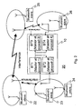
- Fig. 1 shows a block diagram of a Bluetooth relay device 10 according to a preferred embodiment of the invention.
- the relay device comprises a processing unit PU1 (e.g. a microprocessor, a master processing unit or Digital Signal Processor), which controls the operation of the device in accordance with software SW1 stored in a memory MEM1.
- the device further has a number of Bluetooth modules BT1...BT4, having a transceiver circuitry (TRX1...TRX4) and a clock (CLK1...CLK4) for timing the operation of the transceiver circuitry.
- TRX1...TRX4 transceiver circuitry
- CLK1...CLK4 clock
- PU1 controls the Bluetooth modules as will be explained in the following.
- Fig. 2 shows a schematic diagram of the operation of the Bluetooth relay device 10 of Fig. 1 by reference to an exemplary communication system 20.
- five slaves 22 to 26 are within the coverage range of the Bluetooth relay device 10. They each have a connection with one of the Bluetooth modules BT1 to BT4.
- BT1 has been defined as a principal master Bluetooth module and it controls the transmission times of all the other Bluetooth modules so that one Bluetooth module does not receive data whilst another Bluetooth module of the same Bluetooth relay device is transmitting.
- these other Bluetooth modules are configured to assume themselves the role of a master, not of a slave.
- the reception of data is determined at each of the Bluetooth modules (For example, BT4) so that no concurrent transmission occurs by any other Bluetooth module (for example, BT1-BT3).
- BT4 the Bluetooth modules
- BT1-BT3 the Bluetooth module
- the procedure for defining the principal master Bluetooth module according to an embodiment of the invention is described in the following with reference to Fig. 4.
- one or more of the Bluetooth modules may be allowed to operate as slave. In this case, however, the timing of the transmission of such module(s) cannot be controlled by the principal master and thus reception may occur by one module simultaneously with transmission by another module. Hence, a reduction in interference is achieved, but some connection between a transmitter branch and a receiver branch may occur within the relay device.
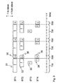
- Fig. 3 shows a timing chart of multi-slot transmissions from the Bluetooth relay device of Fig. 1. This timing chart closely relates to the process shown in Fig. 6.
- the timing chart represents the case wherein BT1 happens to be the principal master and it sends five-slot long packets in bursts occupying five time slots.
- the reception from slave typically follows in the immediately following slot after a transmission.
- Each of the modules BT1 to BT4 sends packets, referred to as 31 to 34, correspondingly.
- Immediately after sending each of the packets 31, 32 and 34 correspondingly packets 35, 36 and 38 are received from the slave.
- Each of the packets 32 to 34 is timed to be sent during the sending of the packet by the principal master that is during the sending of the packet 31 (or transmission time window TW).
- the transmission time window is a period of time during which the packet 31 is sent. Typically, the window matches with this period with the accuracy of a time period taken for transmitting one bit of data of the packet 31.
- this transmission time window is slightly different so that it differs from the time of the transmission of the packet 31 by the duration of one or more bits. Such a difference may cause redundant harm, for example, if it only affects some leading bits (e.g. the preamble) without risking actual header or payload data contained by a packet.
- the packet 33 is of a type such (for example, broadcast or null) that no reception is expected responsively. Therefore, the packet 33 may be sent in any of the five transmission slots, provided it is entirely sent during the sending of the packet 31 (or within the transmission time window TW).
- the sending of the packet 33 need not necessarily end at the same slot as the packet 31, because it is not followed by a received packet. Instead, the packets 32 and 34 are immediately followed by received packets 36 and 38. In order to force the slaves send these packets so that they are received at a right time, in a reception time window RW, the packets 32 and 34 always end in the same slot as the packet 31. In Fig. 3, the reception time window RW is one time slot long.
- the timing of the packets allows co-ordinated reception of packets within the reception time window RW, or while none of the Bluetooth relay device's modules BT1 to BT4 is transmitting. Therefore, the receiver side of these modules can be simplified, as they will not need to tolerate radio transmission by another module in the very same relay device. Furthermore, the error rate will be reduced. This is particularly advantageous in high traffic situations, where occurrence of errors leads to increase of traffic thus causing more collisions, which easily leads to network congestion.
- the synchronisation of transmission slots has been explained with a five-slot long maximum transmitting time window example. It should be understood that correspondingly the invention can be applied so that multiple slots are reserved for receiving data after the transmissions.
- the transmission of data is prevented during all the receiving slots (reception time window RW) and the slaves may transmit data to the relay device in any of the receiving slots (preferably so that the reception ends right before next transmission time window TW).
- the masters i.e. Bluetooth relay device's module's BT1 to BT4 are not allowed to transmit during the reception time windows RW.
- the determination of the reception time windows RW typically follows similar QoS considerations as the transmission of data that will be described in the following.
- the transmissions of all the other Bluetooth modules are restricted to those slots that are used by the principal master. Furthermore, the different Bluetooth modules are each synchronised so that they each start a time slot at practically the same time moment, that is, substantially simultaneously. Even further, the reception by each Bluetooth module is arranged to occur at the time when the principal master (as any other module) does not transmit. It follows that the length of the packets of the principal master determine the transmission time window TW that is the maximum length of all the packets sent by any of the Bluetooth modules.
- different QoS groups are mapped with different priorities for the purpose of choosing the most suitable principal master.
- This mapping can be performed, for example, by primarily preferring high data rate and secondarily preferring fast connections (low round-trip delay) over slower ones, or vice versa.
- the selection of the principal master is performed by the PU1.
- the mapping of QoS groups with different priorities for choosing the principal master according to two different embodiments of the invention.
- QoS group Principal master selection priority Version 1 (high data rate) Version 2 (low delay) 1) Low delay and medium high data rate (video) 2 2 2) Low delay (voice) 3 1 3) Guaranteed data rate 1 3 4) Best effort 4 4
- Each of the Bluetooth modules may have numerous Bluetooth links in operation.
- the priority for each module is defined in accordance with the link that is used for the highest priority transmission.
- a preferred embodiment takes a simpler approach, in which BT1 is always the principal master and the other Bluetooth modules BT2 to BT4 have a fixed order of priority, but the processing unit PU1 assigns the different transmissions to appropriate modules based on the QoS groups so as to define the time windows (TW,RW) used for transmission and reception of data.
- This embodiment greatly simplifies the construction of the relay device 10, as single clock control paths are needed. This approach is particularly useful when all the Bluetooth modules have a 360 degree radio field, that is, when no directional antennas are used.
- the relay device 10 looks for the Bluetooth module that has the highest priority (smallest number in table I). If more than one Bluetooth module has the same QoS group and thus the same priority number, a secondary criterion needs to be applied. For example, let us assume that BT1 has a highest priority transmission going on in QoS group 2 and BT2 in the same QoS group 2, and BT3 and BT4 have corresponding transmissions in QoS groups 3 and 4, respectively. On the other hand, if there are two or more Bluetooth modules each having identical priorities and identical slot requirements, then any one of them can be chosen as the principal master as the transmissions of the others need not be timed differently. It is, however, preferred that the principal master be randomly or rotationally selected in order to provide all the Bluetooth modules similar chances of being selected as the principal master.
- Fig. 4 shows a schematic diagram of the interoperation of different protocol layers of the Bluetooth relay device of Fig. 1 when the Quality of Service (QoS) scheduling is used.
- the Bluetooth modules BT1...BT4 are arranged in a sequence, in a order of their priorities so that the principal master is the first and referred to as BTA, whilst the following Bluetooth modules are referred to as BTB, BTC and BTD.
- Each of the BTA...BTD has layers L2CAP, HCI, LMP, Base band and RF.
- BT1 is constantly assigned to the highest priority QoS group
- BT1 equals to BTA
- BT2 equals to BTB and so forth.
- the principal master (referred to as BTA) is connected with the other Bluetooth modules (BTB, BTC and BTD).
- BTA the principal master
- BTC the other Bluetooth modules
- the base band layer of the principal master thus controls the base band layers of all the Bluetooth modules.
- the LMP and HCI (Host Controller Interface) layers of BTA control the corresponding layers of BTB, BTC and BTD.
- the Bluetooth modules BTA...BTD further have an L2CAP layer (Logical Link Control and Adaptation Protocol). These layers and their use are well known from the art, for example from the Bluetooth, and thus they are not further described.
- each Bluetooth module has separately all the aforementioned layers, which allows easy construction of the system by using basic Bluetooth chips providing these layers. An alternative where a single protocol stack controls numerous Bluetooth modules is next described.
- Fig. 5 shows a schematic diagram of the interoperation of different application layers of the Bluetooth relay device 10 of Fig. 1 when the Quality of Service (QoS) scheduling is used, according to an alternative embodiment.
- a single protocol stack 51 contains the layers L2CAP, HCI and LMP and controls the operation of a plurality of Bluetooth modules. Here it controls all the Bluetooth modules, but in yet another alternative (hybrid) embodiment there are two or more shared Bluetooth protocol stacks connected together and each controlling at least two different Bluetooth modules. These shared stacks are connected together so that the one of them can provide the timing to the other shared stack or stacks in order to synchronise the data communications of Bluetooth modules.
- the advantage of a single Bluetooth protocol stack controlling all the Bluetooth modules is simple control of timing and transmissions for each of thus grouped Bluetooth modules. Further reduction of circuitry may be possible since the layer logic can be gathered into one single unit instead of sharing it amongst various Bluetooth modules of the relay device 10.
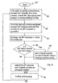
- Fig. 6 shows a flow chart illustrating the operation of the Bluetooth relay device of Fig. 1. Additional advantages are gained by use of a further collision avoidance procedure presented by box 70 drawn with dashed lines. Fig. 6 has the following steps:
- Fig. 7 shows a supplementary procedure 70 to the process of Fig. 6, according to an alternative embodiment.
- the procedure starts and ends from points (A) and (B), as marked in Figs. 6 and 7.
- the supplementary procedure 70 comprises the steps of:
- This alternative embodiment improves the throughput the relay device 10 can reach and reduces errors. Forcing a transmission to wait for another time slot does not seriously deteriorate the service that would use the transmission, because in Bluetooth a time slot is only 625 microseconds long.
Landscapes
- Engineering & Computer Science (AREA)
- Computer Networks & Wireless Communication (AREA)
- Signal Processing (AREA)
- Mobile Radio Communication Systems (AREA)
- Radio Relay Systems (AREA)
- Radar Systems Or Details Thereof (AREA)
- Reduction Or Emphasis Of Bandwidth Of Signals (AREA)
- Time-Division Multiplex Systems (AREA)
- Transition And Organic Metals Composition Catalysts For Addition Polymerization (AREA)
Claims (18)
- Dispositif de communication (10) comprenant :caractérisé en ce queun premier module (BT1) de Radio Fréquence de Faible Puissance (LPRF) pour transmettre les premières données (31) en rafales sur une première liaison LRPF ; etun second module LPRF (BT2) pour transmettre les secondes données (32) en rafales sur une seconde liaison LPRF ;
le dispositif de communication (10) comprend en outre une unité de traitement (PU1) pour choisir une (31) des premières et secondes données (31, 32) et abandonner les autres données non sélectionnées (32) ; et
l'unité de traitement (PU1) est configurée pour :déterminer une fenêtre temporelle (TW) correspondant à la période de transmission d'une rafale de données sélectionnées (31) ; etlimiter la transmission d'une rafale de données non sélectionnées (32) vers ladite fenêtre temporelle (TW), pour synchroniser la transmission des deux rafales au sein de la même fenêtre temporelle (TW). - Dispositif de communication selon la revendication 1, caractérisé en ce que l'unité de traitement (PU1) est en outre configurée par rapport au temps de transmission des données non sélectionnées (32) afin que les transmissions d'une rafale de premières données (31) et d'une rafale de secondes données (32) se terminent en grande partie simultanément.
- Dispositif de communication selon la revendication 1 ou 2, caractérisé en ce que l'unité de traitement (PU1) est en outre configurée pour :attribuer un premier groupe de Qualité de Service (QoS) aux premières données (31 ) ;attribuer un second groupe QoS aux secondes données (32) ; etchoisir la donnée (31) parmi les premières et secondes données (31,32) donnée basée sur le groupe QoS des premières et secondes données.
- Dispositif de communication selon la revendication 3, caractérisé en ce que chaque groupe QoS est mappé selon une priorité prédéterminée afin que différents groupes QoS aient des priorités différentes et ladite sélection de la donnée parmi les premières et secondes données soit effectuée en sélectionnant celle qui présente une priorité plus élevée.
- Dispositif de communication selon la revendication 4, caractérisé en ce que l'unité de traitement (PU1) est configurée pour déterminer de façon répétée lesdites données sélectionnées et ladite fenêtre temporelle (TW) selon la donnée (31) parmi les premières et secondes données (31,32) qui présente une priorité plus élevée afin que les changements de priorité des premières et secondes données (31,32) soient pris en considération.
- Dispositif de communication selon l'une quelconque des revendications précédentes, caractérisé en ce que le dispositif de communication (10) comprend en outre au moins un module LPRF supplémentaire (BT3,BT4) pour transmettre au moins des données supplémentaires (33,34) en rafales sur au moins une liaison LPRF supplémentaire.
- Dispositif de communication selon l'une quelconque des revendications précédentes lorsque jointe à la revendication 3, caractérisé en ce que l'unité de traitement (PU1) est en outre configurée pour :attribuer au moins un groupe QoS supplémentaire pour au moins des données supplémentaires (33,34) ; etchoisir la donnée (31) parmi les premières, deuxièmes et au moins une des données supplémentaires (31,32,33) qui présente une priorité la plus élevée.
- Dispositif de communication selon l'une quelconque des revendications précédentes, caractérisé en ce que ledit dispositif de communication (10) est choisi dans un groupe comprenant : un dispositif de communication mobile et un dispositif relais LPRF.
- Dispositif de communication selon l'une quelconque des revendications précédentes, caractérisé en ce que l'unité de traitement (PU1) est en outre configurée pour permettre à seulement un module LPRF (BT1, BT2, BT3, BT4) à la fois de transmettre sur un canal.
- Dispositif de communication selon l'une quelconque des revendications précédentes, caractérisé en ce que lesdites première et seconde liaisons LPRF sont des liaisons Bluetooth.
- Système de communication ayant un premier, deuxième et troisième dispositifs de communication (10,22,23), lesdits deuxième et troisième dispositifs de communication (22,23) comprenant chacun un module de Radio Fréquence de Faible Puissance (LPRF) pour communiquer avec le premier dispositif de communication (10) et le premier dispositif de communication (10) comprenant :caractérisé en ce queun premier module LPRF (BT1) pour transmettre les premières données (3 1) en rafales sur une première liaison LPRF au deuxième dispositif de communication (22) ; etun second module LPRF (BT2) pour transmettre les secondes données (32) en rafales sur une seconde liaison LPRF au troisième dispositif de communication (23) ;
le dispositif de communication (10) comprend en outre une unité de traitement (PU1) pour choisir une (31) des premières et secondes données (31,32) et abandonner les autres données non sélectionnées (32) ; et
l'unité de traitement (PU 1) est configurée pour :déterminer une fenêtre temporelle (TW) correspondant à la période de transmission d'une rafale de données sélectionnées (31) ; etlimiter la transmission d'une rafale de données non sélectionnées (32) vers ladite fenêtre temporelle (TW), pour synchroniser la transmission de deux rafales au sein de la même fenêtre temporelle (TW). - Système de communication selon la revendication 11, caractérisé en ce que ledit premier dispositif de communication (10) est un dispositif relais LPRF.
- Dispositif de communication selon la revendication 11 ou 12, caractérisé en ce qu'au moins un des deuxième et troisième dispositifs de communication (22,23) est un dispositif de communication mobile.
- Procédé de communication comprenant les étapes consistant à :caractérisé en ce quetransmettre les premières données (31) en rafales à partir d'un dispositif de communication (10) sur une première liaison radio fréquence de faible puissance (LPRF) ; ettransmettre (73) les secondes données (32) en rafales à partir du dispositif de communication (10) sur une seconde liaison LPRF ;
le procédé comprend en outre les étapes consistant à :choisir (67) une (31) des premières et secondes données (31,32) et abandonner les autres données non sélectionnées (32) :déterminer une fenêtre temporelle (TW) correspondant à la période de transmission d'une rafale de données sélectionnées (31) ; etlimiter la transmission d'une rafale de données non sélectionnées (32) vers ladite fenêtre de temps (TW), pour synchroniser la transmission des deux rafales au sein de la même fenêtre temporelle (TW). - Procédé selon la revendication 14, caractérisé en ce que le procédé comprend en outre l'étape de synchronisation de la transmission de données non sélectionnées (32) afin que les deux transmissions d'une rafale de premières et secondes données (31,32) se terminent en grande partie simultanément.
- Procédé selon la revendication 14 ou 15, caractérisé en ce que le procédé comprend en outre les étapes consistant à :exécuter ladite transmission des premières données (31) par un premier module LPRF ;exécuter ladite transmission des secondes données (32) par un second module LPRF ;attribuer un premier groupe de Qualité de Service (QoS) aux premières données (31) ;attribuer un second groupe QoS aux secondes données (32) ; etchoisir la donnée (31) parmi les premières et secondes données (31,32) qui présente une priorité plus élevée.
- Procédé selon l'une quelconque des revendications 14 à 16, caractérisé en ce que le procédé comprend en outre les étapes consistant à :transmettre des données par au moins un client externe (23,24) au dispositif de communication ;déterminer une période intermédiaire (RW) entre deux fenêtres temporelles consécutives desdites fenêtres temporelles (TW) ; etlimiter les données transmises (35,36,38) par au moins le client externe (23,24) vers ladite période intermédiaire (RW).
- Programme de calcul pour contrôler un dispositif de communication (10), comprenant :caractérisé en ce quecode de programme de calcul pour entraíner le dispositif de communication à transmettre les premières données (31) en rafales à partir d'un dispositif de communication sur une première liaison radio fréquence de faible puissance (LPRF) ; etcode de programme de calcul pour entraíner le dispositif de communication à transmettre les secondes données (32) en rafales à partir d'un dispositif de communication sur une seconde liaison LPRF :
le programme de calcul comprend en outre :code de programme de calcul pour entraíner le dispositif de communication à choisir une (31) des premières et secondes données (31,32) et abandonner les autres données non sélectionnées (32) ;code de programme de calcul pour entraíner le dispositif de communication à déterminer une fenêtre temporelle (TW) correspondant à la période de transmission d'une rafale de données sélectionnées (31) ; etcode de programme de calcul pour entraíner le dispositif de communication à limiter la transmission d'une rafale de données non sélectionnées (32) vers ladite fenêtre temporelle (TW), pour synchroniser la transmission de deux rafales au sein de la même fenêtre temporelle (TW).
Applications Claiming Priority (3)
| Application Number | Priority Date | Filing Date | Title |
|---|---|---|---|
| FI20011359A FI20011359A0 (fi) | 2001-06-25 | 2001-06-25 | Häiriön vähentäminen |
| FI20011359 | 2001-06-25 | ||
| US10/183,808 US7190690B2 (en) | 2001-06-25 | 2002-06-25 | Interference reduction |
Publications (3)
| Publication Number | Publication Date |
|---|---|
| EP1271853A2 EP1271853A2 (fr) | 2003-01-02 |
| EP1271853A3 EP1271853A3 (fr) | 2003-11-05 |
| EP1271853B1 true EP1271853B1 (fr) | 2004-08-18 |
Family
ID=32893069
Family Applications (1)
| Application Number | Title | Priority Date | Filing Date |
|---|---|---|---|
| EP02396099A Expired - Lifetime EP1271853B1 (fr) | 2001-06-25 | 2002-06-24 | Dispositif de communication, procédé et système pour la réduction de l'interférence |
Country Status (9)
| Country | Link |
|---|---|
| US (1) | US7190690B2 (fr) |
| EP (1) | EP1271853B1 (fr) |
| JP (1) | JP3902516B2 (fr) |
| CN (1) | CN1236584C (fr) |
| AT (1) | ATE274267T1 (fr) |
| DE (1) | DE60200981T2 (fr) |
| DK (1) | DK1271853T3 (fr) |
| ES (1) | ES2224041T3 (fr) |
| FI (1) | FI20011359A0 (fr) |
Families Citing this family (32)
| Publication number | Priority date | Publication date | Assignee | Title |
|---|---|---|---|---|
| US20040001530A1 (en) * | 2002-06-27 | 2004-01-01 | International Business Machines Corporation | Insertion of null packets to mitigate the effects of interference in wireless communications |
| JP3973092B2 (ja) * | 2002-09-20 | 2007-09-05 | 本田技研工業株式会社 | 無線ネットワークシステムおよび無線通信方法 |
| US7420952B2 (en) * | 2002-10-28 | 2008-09-02 | Mesh Dynamics, Inc. | High performance wireless networks using distributed control |
| US11368537B2 (en) | 2002-10-28 | 2022-06-21 | Dynamic Mesh Networks, Inc. | High performance wireless network |
| WO2004066539A2 (fr) * | 2003-01-15 | 2004-08-05 | Symbol Technologies, Inc. | Points d'accès sans fil de luminaires |
| US20050128991A1 (en) * | 2003-05-08 | 2005-06-16 | Sriram Dayanandan | Coordination between simultaneously operating Pico-Nets in high mobility wireless networks |
| JP2005051468A (ja) * | 2003-07-28 | 2005-02-24 | Sony Chem Corp | ドアホンシステム及び信号送受信方法、並びにドアホン親装置及びドアホン子装置 |
| US7474677B2 (en) | 2003-08-12 | 2009-01-06 | Bose Corporation | Wireless communicating |
| US8442019B2 (en) | 2003-08-12 | 2013-05-14 | Bose Corporation | Method and apparatus for avoiding wireless audio signal transmission interferences |
| GB0328435D0 (en) | 2003-12-08 | 2004-01-14 | Tdk Systems Europ Ltd | Bluetooth communications |
| JP4389575B2 (ja) * | 2003-12-17 | 2009-12-24 | パナソニック株式会社 | 無線中継装置 |
| JP4179552B2 (ja) * | 2003-12-18 | 2008-11-12 | 本田技研工業株式会社 | ブルートゥース端末 |
| DE102004061934A1 (de) * | 2004-12-22 | 2006-07-13 | Siemens Ag | Verfahren zur Datenübertragung zwischen einer sendenden und einer empfangenden Einheit in einem Bluetooth-Funkkommunikationssystem |
| US9635625B2 (en) * | 2005-12-28 | 2017-04-25 | Google Technology Holdings LLC | Method for switching between predefined transmit power classes on a mobile telecommunications device |
| US7693128B2 (en) * | 2006-02-23 | 2010-04-06 | Freescale Semiconductor, Inc. | Managing packets for transmission in a communication system |
| JP4675816B2 (ja) * | 2006-04-07 | 2011-04-27 | 株式会社エヌ・ティ・ティ・ドコモ | 通信端末及びリスト表示方法 |
| JP2007287040A (ja) * | 2006-04-19 | 2007-11-01 | Fujitsu Ltd | コンテキスト情報収集システム、その処理方式及びそのシステムで用いられる装置 |
| US10013381B2 (en) | 2006-08-31 | 2018-07-03 | Bose Corporation | Media playing from a docked handheld media device |
| US8320410B2 (en) * | 2007-05-23 | 2012-11-27 | Broadcom Corporation | Synchronization of media data streams with separate sinks using a relay |
| US8102836B2 (en) * | 2007-05-23 | 2012-01-24 | Broadcom Corporation | Synchronization of a split audio, video, or other data stream with separate sinks |
| CN101252505B (zh) * | 2007-09-21 | 2011-01-12 | 广州市聚晖电子科技有限公司 | 一种射频中继器的自动注册与更新路径系统 |
| CN102035574B (zh) * | 2009-09-29 | 2013-06-19 | 原相科技股份有限公司 | 可降低无线资源耗费的传输方法及其相关装置 |
| CN102378202B (zh) * | 2010-08-19 | 2014-06-04 | 中国移动通信集团甘肃有限公司 | 无线网络覆盖方法、装置及系统 |
| KR20120017821A (ko) * | 2010-08-20 | 2012-02-29 | 삼성전자주식회사 | 휴대용 단말기에서 데이터를 공유하기 위한 장치 및 방법 |
| US8457020B2 (en) | 2010-08-20 | 2013-06-04 | Research In Motion Limited | Methods and apparatus for providing communications with use of first and second RF transceiver modules |
| CN102072665B (zh) * | 2010-12-31 | 2012-11-14 | 陕西科技大学 | 热处理炉的远距离手机无线监控装置和监控方法 |
| CN102547486A (zh) * | 2011-01-04 | 2012-07-04 | 上海华勤通讯技术有限公司 | 蓝牙耳机对讲系统 |
| GB201109520D0 (en) * | 2011-06-07 | 2011-07-20 | Nordic Semiconductor Asa | Synchronised radio transreceiver |
| US9026168B2 (en) * | 2013-09-26 | 2015-05-05 | L-3 Communications Corp. | Transmitting portions of a data block in transmission bursts from a plurality of transmitters |
| CN106664289B (zh) * | 2014-08-28 | 2020-07-07 | 瑞典爱立信有限公司 | 用于实现数据传输的干扰管理的通信设备和方法 |
| WO2020024199A1 (fr) * | 2018-08-02 | 2020-02-06 | Texas Instruments Incorporated | Interface numérique flexled à haute vitesse |
| US11057748B1 (en) * | 2018-09-17 | 2021-07-06 | Synapse Wireless, Inc. | Prioritized communication windows in a wireless mesh network |
Family Cites Families (6)
| Publication number | Priority date | Publication date | Assignee | Title |
|---|---|---|---|---|
| SE514264C2 (sv) * | 1999-05-07 | 2001-01-29 | Ericsson Telefon Ab L M | Ett kommunikationssystem |
| AUPQ412899A0 (en) * | 1999-11-18 | 1999-12-09 | Prescient Networks Pty Ltd | A gateway system for interconnecting wireless ad-hoc networks |
| US6975613B1 (en) * | 1999-12-06 | 2005-12-13 | Telefonaktiebolaget L M Ericsson (Publ) | System and method for scheduling communication sessions in an ad-hoc network |
| US6745027B2 (en) * | 2000-12-22 | 2004-06-01 | Seekernet Incorporated | Class switched networks for tracking articles |
| FR2821514B1 (fr) * | 2001-02-28 | 2003-06-13 | Jacques Lewiner | Systeme de radiocommunication local |
| US6873825B2 (en) * | 2002-01-10 | 2005-03-29 | Qualcomm, Incorporated | System and method for optimizing bluetooth transmissions to overcome signal interference |
-
2001
- 2001-06-25 FI FI20011359A patent/FI20011359A0/fi unknown
-
2002
- 2002-06-24 EP EP02396099A patent/EP1271853B1/fr not_active Expired - Lifetime
- 2002-06-24 DK DK02396099T patent/DK1271853T3/da active
- 2002-06-24 DE DE60200981T patent/DE60200981T2/de not_active Expired - Lifetime
- 2002-06-24 ES ES02396099T patent/ES2224041T3/es not_active Expired - Lifetime
- 2002-06-24 AT AT02396099T patent/ATE274267T1/de not_active IP Right Cessation
- 2002-06-25 US US10/183,808 patent/US7190690B2/en not_active Expired - Fee Related
- 2002-06-25 JP JP2002184977A patent/JP3902516B2/ja not_active Expired - Fee Related
- 2002-06-25 CN CN02140361.9A patent/CN1236584C/zh not_active Expired - Fee Related
Also Published As
| Publication number | Publication date |
|---|---|
| FI20011359A0 (fi) | 2001-06-25 |
| DE60200981D1 (de) | 2004-09-23 |
| JP3902516B2 (ja) | 2007-04-11 |
| ES2224041T3 (es) | 2005-03-01 |
| JP2003101500A (ja) | 2003-04-04 |
| EP1271853A3 (fr) | 2003-11-05 |
| EP1271853A2 (fr) | 2003-01-02 |
| CN1236584C (zh) | 2006-01-11 |
| US20030235179A1 (en) | 2003-12-25 |
| DK1271853T3 (da) | 2005-02-28 |
| US7190690B2 (en) | 2007-03-13 |
| ATE274267T1 (de) | 2004-09-15 |
| CN1395396A (zh) | 2003-02-05 |
| DE60200981T2 (de) | 2005-01-05 |
Similar Documents
| Publication | Publication Date | Title |
|---|---|---|
| EP1271853B1 (fr) | Dispositif de communication, procédé et système pour la réduction de l'interférence | |
| US7046649B2 (en) | Interoperability for bluetooth/IEEE 802.11 | |
| US7039031B1 (en) | Integrating communications networks | |
| US6975613B1 (en) | System and method for scheduling communication sessions in an ad-hoc network | |
| JP3847722B2 (ja) | 時分割マルチセクタ無線lan装置 | |
| JP3968514B2 (ja) | 無線通信システム、無線通信装置及び無線通信方法、並びにコンピュータ・プログラム | |
| EP1860827B1 (fr) | Procédé et système pour la sélection automatique d'une priorité de coexistence pour un lien SCO | |
| JP3455227B2 (ja) | 無線通信の方法 | |
| US6920171B2 (en) | Multiple access frequency hopping network with interference anticipation | |
| US6967944B2 (en) | Increasing link capacity via concurrent transmissions in centralized wireless LANs | |
| US7643463B1 (en) | Method and apparatus for a dual-mode radio in a wireless communication system | |
| JP5295882B2 (ja) | 無線通信装置 | |
| US20050276241A1 (en) | Wireless LAN with fragmentation for bluetooth coexistence | |
| US20020126692A1 (en) | System and method for providing quality of service and contention resolution in ad-hoc communication systems | |
| KR20080044285A (ko) | 동적 스펙트럼 접근 무선 시스템에서의 스펙트럼 관리 | |
| WO2001011833A1 (fr) | Reseau sans fil extremement rapide possedant une voie fiable sans fil a debit binaire limite | |
| EP1229693B1 (fr) | Appareil de communications sans fil, méthode et système de communication sans fil utilisant le même | |
| Hwang et al. | A receiver-centric multi-channel MAC protocol for wireless networks | |
| CN101355553A (zh) | 基于无线网状网中的流量负载自适应地提高吞吐量的方法 | |
| US7656962B2 (en) | Method for transmitting signals in a radio communication system | |
| Rangnekar et al. | Multiple channel scheduling in UWB based IEEE 802.15. 3 networks | |
| Qiang et al. | CDMA-based carrier sense multiple access protocol for wireless LAN | |
| Taneja et al. | QoS Improvement in MANET Using Multi-Channel MAC Framework | |
| US7180903B1 (en) | Resource management in uncoordinated frequency hopping system | |
| JP2000102067A (ja) | 通信方式及び子機装置 |
Legal Events
| Date | Code | Title | Description |
|---|---|---|---|
| EUG | Se: european patent has lapsed | ||
| PUAI | Public reference made under article 153(3) epc to a published international application that has entered the european phase |
Free format text: ORIGINAL CODE: 0009012 |
|
| AK | Designated contracting states |
Kind code of ref document: A2 Designated state(s): AT BE CH CY DE DK ES FI FR GB GR IE IT LI LU MC NL PT SE TR |
|
| AX | Request for extension of the european patent |
Free format text: AL;LT;LV;MK;RO;SI |
|
| PUAL | Search report despatched |
Free format text: ORIGINAL CODE: 0009013 |
|
| AK | Designated contracting states |
Kind code of ref document: A3 Designated state(s): AT BE CH CY DE DK ES FI FR GB GR IE IT LI LU MC NL PT SE TR |
|
| AX | Request for extension of the european patent |
Extension state: AL LT LV MK RO SI |
|
| 17P | Request for examination filed |
Effective date: 20031004 |
|
| GRAP | Despatch of communication of intention to grant a patent |
Free format text: ORIGINAL CODE: EPIDOSNIGR1 |
|
| GRAS | Grant fee paid |
Free format text: ORIGINAL CODE: EPIDOSNIGR3 |
|
| GRAA | (expected) grant |
Free format text: ORIGINAL CODE: 0009210 |
|
| AKX | Designation fees paid |
Designated state(s): AT BE CH CY DE DK ES FI FR GB GR IE IT LI LU MC NL PT SE TR |
|
| AK | Designated contracting states |
Kind code of ref document: B1 Designated state(s): AT BE CH CY DE DK ES FI FR GB GR IE IT LI LU MC NL PT SE TR |
|
| PG25 | Lapsed in a contracting state [announced via postgrant information from national office to epo] |
Ref country code: CH Free format text: LAPSE BECAUSE OF FAILURE TO SUBMIT A TRANSLATION OF THE DESCRIPTION OR TO PAY THE FEE WITHIN THE PRESCRIBED TIME-LIMIT Effective date: 20040818 Ref country code: TR Free format text: LAPSE BECAUSE OF FAILURE TO SUBMIT A TRANSLATION OF THE DESCRIPTION OR TO PAY THE FEE WITHIN THE PRESCRIBED TIME-LIMIT Effective date: 20040818 Ref country code: LI Free format text: LAPSE BECAUSE OF FAILURE TO SUBMIT A TRANSLATION OF THE DESCRIPTION OR TO PAY THE FEE WITHIN THE PRESCRIBED TIME-LIMIT Effective date: 20040818 Ref country code: AT Free format text: LAPSE BECAUSE OF FAILURE TO SUBMIT A TRANSLATION OF THE DESCRIPTION OR TO PAY THE FEE WITHIN THE PRESCRIBED TIME-LIMIT Effective date: 20040818 Ref country code: BE Free format text: LAPSE BECAUSE OF FAILURE TO SUBMIT A TRANSLATION OF THE DESCRIPTION OR TO PAY THE FEE WITHIN THE PRESCRIBED TIME-LIMIT Effective date: 20040818 |
|
| REG | Reference to a national code |
Ref country code: GB Ref legal event code: FG4D |
|
| REG | Reference to a national code |
Ref country code: CH Ref legal event code: EP |
|
| REG | Reference to a national code |
Ref country code: IE Ref legal event code: FG4D |
|
| REF | Corresponds to: |
Ref document number: 60200981 Country of ref document: DE Date of ref document: 20040923 Kind code of ref document: P |
|
| PG25 | Lapsed in a contracting state [announced via postgrant information from national office to epo] |
Ref country code: GR Free format text: LAPSE BECAUSE OF FAILURE TO SUBMIT A TRANSLATION OF THE DESCRIPTION OR TO PAY THE FEE WITHIN THE PRESCRIBED TIME-LIMIT Effective date: 20041118 |
|
| REG | Reference to a national code |
Ref country code: SE Ref legal event code: TRGR |
|
| ET | Fr: translation filed | ||
| REG | Reference to a national code |
Ref country code: DK Ref legal event code: T3 Ref country code: CH Ref legal event code: PL |
|
| REG | Reference to a national code |
Ref country code: ES Ref legal event code: FG2A Ref document number: 2224041 Country of ref document: ES Kind code of ref document: T3 |
|
| PG25 | Lapsed in a contracting state [announced via postgrant information from national office to epo] |
Ref country code: LU Free format text: LAPSE BECAUSE OF NON-PAYMENT OF DUE FEES Effective date: 20050624 Ref country code: IE Free format text: LAPSE BECAUSE OF NON-PAYMENT OF DUE FEES Effective date: 20050624 Ref country code: CY Free format text: LAPSE BECAUSE OF FAILURE TO SUBMIT A TRANSLATION OF THE DESCRIPTION OR TO PAY THE FEE WITHIN THE PRESCRIBED TIME-LIMIT Effective date: 20050624 |
|
| PLBE | No opposition filed within time limit |
Free format text: ORIGINAL CODE: 0009261 |
|
| STAA | Information on the status of an ep patent application or granted ep patent |
Free format text: STATUS: NO OPPOSITION FILED WITHIN TIME LIMIT |
|
| PG25 | Lapsed in a contracting state [announced via postgrant information from national office to epo] |
Ref country code: MC Free format text: LAPSE BECAUSE OF NON-PAYMENT OF DUE FEES Effective date: 20050630 |
|
| 26N | No opposition filed |
Effective date: 20050519 |
|
| REG | Reference to a national code |
Ref country code: IE Ref legal event code: MM4A |
|
| PGFP | Annual fee paid to national office [announced via postgrant information from national office to epo] |
Ref country code: SE Payment date: 20060607 Year of fee payment: 5 |
|
| PG25 | Lapsed in a contracting state [announced via postgrant information from national office to epo] |
Ref country code: PT Free format text: LAPSE BECAUSE OF NON-PAYMENT OF DUE FEES Effective date: 20050118 |
|
| EUG | Se: european patent has lapsed | ||
| PG25 | Lapsed in a contracting state [announced via postgrant information from national office to epo] |
Ref country code: SE Free format text: LAPSE BECAUSE OF NON-PAYMENT OF DUE FEES Effective date: 20070625 |
|
| PGFP | Annual fee paid to national office [announced via postgrant information from national office to epo] |
Ref country code: DK Payment date: 20100610 Year of fee payment: 9 Ref country code: FI Payment date: 20100610 Year of fee payment: 9 Ref country code: FR Payment date: 20100709 Year of fee payment: 9 |
|
| PGFP | Annual fee paid to national office [announced via postgrant information from national office to epo] |
Ref country code: IT Payment date: 20100617 Year of fee payment: 9 |
|
| PGFP | Annual fee paid to national office [announced via postgrant information from national office to epo] |
Ref country code: ES Payment date: 20100713 Year of fee payment: 9 Ref country code: NL Payment date: 20100603 Year of fee payment: 9 |
|
| PGFP | Annual fee paid to national office [announced via postgrant information from national office to epo] |
Ref country code: DE Payment date: 20100616 Year of fee payment: 9 Ref country code: GB Payment date: 20100623 Year of fee payment: 9 |
|
| REG | Reference to a national code |
Ref country code: NL Ref legal event code: V1 Effective date: 20120101 |
|
| PG25 | Lapsed in a contracting state [announced via postgrant information from national office to epo] |
Ref country code: FI Free format text: LAPSE BECAUSE OF NON-PAYMENT OF DUE FEES Effective date: 20110624 |
|
| REG | Reference to a national code |
Ref country code: DK Ref legal event code: EBP |
|
| GBPC | Gb: european patent ceased through non-payment of renewal fee |
Effective date: 20110624 |
|
| PG25 | Lapsed in a contracting state [announced via postgrant information from national office to epo] |
Ref country code: IT Free format text: LAPSE BECAUSE OF NON-PAYMENT OF DUE FEES Effective date: 20110624 |
|
| REG | Reference to a national code |
Ref country code: FR Ref legal event code: ST Effective date: 20120229 |
|
| REG | Reference to a national code |
Ref country code: DE Ref legal event code: R119 Ref document number: 60200981 Country of ref document: DE Effective date: 20120103 |
|
| PG25 | Lapsed in a contracting state [announced via postgrant information from national office to epo] |
Ref country code: DE Free format text: LAPSE BECAUSE OF NON-PAYMENT OF DUE FEES Effective date: 20120103 Ref country code: FR Free format text: LAPSE BECAUSE OF NON-PAYMENT OF DUE FEES Effective date: 20110630 |
|
| PG25 | Lapsed in a contracting state [announced via postgrant information from national office to epo] |
Ref country code: NL Free format text: LAPSE BECAUSE OF NON-PAYMENT OF DUE FEES Effective date: 20120101 |
|
| PG25 | Lapsed in a contracting state [announced via postgrant information from national office to epo] |
Ref country code: GB Free format text: LAPSE BECAUSE OF NON-PAYMENT OF DUE FEES Effective date: 20110624 |
|
| PG25 | Lapsed in a contracting state [announced via postgrant information from national office to epo] |
Ref country code: DK Free format text: LAPSE BECAUSE OF NON-PAYMENT OF DUE FEES Effective date: 20110630 |
|
| REG | Reference to a national code |
Ref country code: ES Ref legal event code: FD2A Effective date: 20121116 |
|
| PG25 | Lapsed in a contracting state [announced via postgrant information from national office to epo] |
Ref country code: ES Free format text: LAPSE BECAUSE OF NON-PAYMENT OF DUE FEES Effective date: 20110625 |