US8102836B2 - Synchronization of a split audio, video, or other data stream with separate sinks - Google Patents
Synchronization of a split audio, video, or other data stream with separate sinks Download PDFInfo
- Publication number
- US8102836B2 US8102836B2 US11/752,880 US75288007A US8102836B2 US 8102836 B2 US8102836 B2 US 8102836B2 US 75288007 A US75288007 A US 75288007A US 8102836 B2 US8102836 B2 US 8102836B2
- Authority
- US
- United States
- Prior art keywords
- output
- clock signal
- data
- source
- codec
- Prior art date
- Legal status (The legal status is an assumption and is not a legal conclusion. Google has not performed a legal analysis and makes no representation as to the accuracy of the status listed.)
- Active, expires
Links
Images


Classifications
-
- H—ELECTRICITY
- H04—ELECTRIC COMMUNICATION TECHNIQUE
- H04L—TRANSMISSION OF DIGITAL INFORMATION, e.g. TELEGRAPHIC COMMUNICATION
- H04L47/00—Traffic control in data switching networks
- H04L47/10—Flow control; Congestion control
- H04L47/38—Flow control; Congestion control by adapting coding or compression rate
-
- H—ELECTRICITY
- H04—ELECTRIC COMMUNICATION TECHNIQUE
- H04L—TRANSMISSION OF DIGITAL INFORMATION, e.g. TELEGRAPHIC COMMUNICATION
- H04L43/00—Arrangements for monitoring or testing data switching networks
- H04L43/08—Monitoring or testing based on specific metrics, e.g. QoS, energy consumption or environmental parameters
- H04L43/0852—Delays
- H04L43/0864—Round trip delays
-
- H—ELECTRICITY
- H04—ELECTRIC COMMUNICATION TECHNIQUE
- H04L—TRANSMISSION OF DIGITAL INFORMATION, e.g. TELEGRAPHIC COMMUNICATION
- H04L47/00—Traffic control in data switching networks
- H04L47/10—Flow control; Congestion control
-
- H—ELECTRICITY
- H04—ELECTRIC COMMUNICATION TECHNIQUE
- H04L—TRANSMISSION OF DIGITAL INFORMATION, e.g. TELEGRAPHIC COMMUNICATION
- H04L47/00—Traffic control in data switching networks
- H04L47/10—Flow control; Congestion control
- H04L47/25—Flow control; Congestion control with rate being modified by the source upon detecting a change of network conditions
-
- H—ELECTRICITY
- H04—ELECTRIC COMMUNICATION TECHNIQUE
- H04W—WIRELESS COMMUNICATION NETWORKS
- H04W28/00—Network traffic management; Network resource management
- H04W28/02—Traffic management, e.g. flow control or congestion control
-
- H—ELECTRICITY
- H04—ELECTRIC COMMUNICATION TECHNIQUE
- H04W—WIRELESS COMMUNICATION NETWORKS
- H04W56/00—Synchronisation arrangements
- H04W56/001—Synchronization between nodes
- H04W56/0015—Synchronization between nodes one node acting as a reference for the others
-
- H—ELECTRICITY
- H04—ELECTRIC COMMUNICATION TECHNIQUE
- H04W—WIRELESS COMMUNICATION NETWORKS
- H04W8/00—Network data management
- H04W8/02—Processing of mobility data, e.g. registration information at HLR [Home Location Register] or VLR [Visitor Location Register]; Transfer of mobility data, e.g. between HLR, VLR or external networks
- H04W8/04—Registration at HLR or HSS [Home Subscriber Server]
-
- H—ELECTRICITY
- H04—ELECTRIC COMMUNICATION TECHNIQUE
- H04L—TRANSMISSION OF DIGITAL INFORMATION, e.g. TELEGRAPHIC COMMUNICATION
- H04L43/00—Arrangements for monitoring or testing data switching networks
- H04L43/10—Active monitoring, e.g. heartbeat, ping or trace-route
- H04L43/106—Active monitoring, e.g. heartbeat, ping or trace-route using time related information in packets, e.g. by adding timestamps
Definitions
- the present invention relates to the synchronization of sink devices that receive data, such as audio and/or video data, wirelessly streamed by a source device.
- Wireless communication protocols such as the BLUETOOTH protocol, enable a variety of types of data streams to be provided by source devices to sink devices in a wireless fashion.
- audio and video data may be streamed by the source devices to the sink devices.
- audio data may be transmitted by a music player to wireless speakers. It is desirable for the audio outputs of the speakers to be synchronized so that the audio may be heard clearly, and in stereo, by a listener.
- video data may be transmitted by a video source to wireless video display devices.
- a media source may transmit audio data to one or more wireless speakers and video data to one or more wireless display devices. It may be desirable that the audio sound and video image streams output by the speaker(s) and display(s) be synchronized for synchronized listening and viewing by the audience.
- Each sink device receives a stream of data from a source device.
- a data output latency is determined, and is compared against a desired data output latency, to determine a latency difference.
- a rate of data output by each sink device is adjusted according to the determined latency difference, to synchronize a timing of data output across the sink devices.
- each sink device executes a similar process: a communication packet is received from the source device.
- the communication packet includes data and a source clock timestamp.
- a local clock signal is generated that is synchronized with a source clock signal of the source device.
- the data is decoded using a codec.
- At least one delay and the source clock timestamp are subtracted from a current value of the local clock signal to generate a local latency value.
- a difference between a desired latency value and the local latency value is determined.
- a rate of a clock signal of the codec is adjusted according to the determined difference.
- an output system for data streamed from a source device includes one or more output/sink devices, each sink device including a radio frequency (RF) communication module, a local clock signal generator, a codec, an output element, and a latency calculator.
- the RF communication module is configured to receive a communication packet from a source device.
- the communication packet includes data and a source clock timestamp.
- the local clock signal generator is configured to generate a local clock signal synchronized with a source clock signal of the source device.
- the codec is configured to decode the data, and to optionally convert the decoded data to analog form.
- the output element is configured to receive the decoded data and generate an output signal.
- the latency calculator is configured to subtract at least one delay and the source clock timestamp from a current value of the local clock signal to generate a local latency value.
- the latency calculator further determines a difference between a desired latency value and the local latency value. A rate of the codec clock signal is adjusted according to the determined difference.
- the data may be audio data, video data, or other type(s) of data.
- the output element for each sink device may be a speaker, a display device, or other type of output element.
- a variety of communication protocols may be used for communications between the source device and sink device(s), such as the BLUETOOTH protocol.
- the source clock signal may be the BLUETOOTH master clock
- the local clock signal(s) may be BLUETOOTH slave clock(s).
- FIGS. 1 and 2 show block diagram views of an example BLUETOOTH wireless communications system.
- FIG. 3 shows a flowchart for synchronization of devices in a BLUETOOTH piconet.
- FIG. 4 shows an example synchronization packet.
- FIG. 5 shows an example BLUETOOTH wireless communication system, according to an embodiment of the present invention.
- FIG. 6 shows a flowchart providing example steps for a process operating in a sink device to enable synchronized data output with other sink devices, according to example embodiments of the present invention.
- FIG. 7 shows an example communication packet that may be received by a sink device from a source device, according to an example embodiment of the present invention.
- FIG. 8 shows a block diagram of an example source device, according to an embodiment of the present invention.
- FIG. 9 shows a block diagram of an example sink device, according to an embodiment of the present invention.
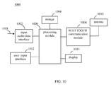
- FIG. 10 shows a block diagram of an example music player, according to an embodiment of the present invention.
- FIG. 11 shows a block diagram of an example earphone device, according to an embodiment of the present invention.
- FIG. 12 shows an example audio/video system, according to an embodiment of the present invention.
- FIG. 13 shows an example multi-display video system, according to an embodiment of the present invention.
- references in the specification to “one embodiment,” “an embodiment,” “an example embodiment,” etc., indicate that the embodiment described may include a particular feature, structure, or characteristic, but every embodiment may not necessarily include the particular feature, structure, or characteristic. Moreover, such phrases are not necessarily referring to the same embodiment. Further, when a particular feature, structure, or characteristic is described in connection with an embodiment, it is submitted that it is within the knowledge of one skilled in the art to effect such feature, structure, or characteristic in connection with other embodiments whether or not explicitly described.
- FIG. 1 shows an example BLUETOOTH wireless communication system 100 .
- system 100 includes a source device 102 , a first sink device 104 a , and a second sink device 104 b .
- Source device 102 may be any type of device, mobile or immobile, that is configured to provide a stream of data to one or more sink devices 104 , such as a pair of sink devices 104 a and 104 b .
- source device 102 may be an audio source device such as a music player (e.g., an MP3 player, an APPLE IPOD, etc.) or mobile phone (e.g., a cell phone), a video source device (e.g., a cable box that supplies digital video, an analog video signal receiver or tuner, etc.) a mixed media source device (e.g., a stereo receiver that sources video and audio), or a device (e.g., a computer system) that sources other types of data streams.
- a music player e.g., an MP3 player, an APPLE IPOD, etc.
- mobile phone e.g., a cell phone
- video source device e.g., a cable box that supplies digital video, an analog video signal receiver or tuner, etc.
- a mixed media source device e.g., a stereo receiver that sources video and audio
- a device e.g., a computer system
- Sink devices 102 may be any type of device that receives and processes a received data stream, such as a wireless speaker (e.g., an earphone or headset speaker, a home audio speaker, etc.), a wireless display device (e.g., a wireless flat screen television, including a high-definition television), or other device.
- a wireless speaker e.g., an earphone or headset speaker, a home audio speaker, etc.
- a wireless display device e.g., a wireless flat screen television, including a high-definition television
- source device 102 includes a BLUETOOTH communication module 106
- first sink device 104 a includes a BLUETOOTH communication module 108 a
- second sink device 104 b includes a BLUETOOTH communication module 108 b
- BLUETOOTH communication module 106 enables master device 102 to communicate with first and second sink devices 104 a and 104 b according to a BLUETOOTH communication protocol.
- BLUETOOTH communication module 106 communicates with BLUETOOTH communication module 108 a using a first communication channel 110 a , and communicates with BLUETOOTH communication module 108 b of second sink device 104 b using a second communication channel 110 b .
- first and second communication channels 110 a and 110 b may each include RF communication signals transmitted in a unicast (point-to-point; uni- or bi-directional) channel manner between source device 102 and a respective, designated one of first and second sink devices 104 a and 104 b .
- first and second communication channels 110 a and 110 b may be broadcast (unidirectional) channels between source device 102 and first and second sink devices 104 a and 104 b.
- FIG. 2 shows BLUETOOTH communication module 106 communicating with BLUETOOTH communication modules 108 a and 108 b to form a BLUETOOTH piconet 200 that includes source device 102 , first sink device 104 a , and second sink device 104 b .
- source device 102 is a “master” device of piconet 200
- first and second sink devices 104 a and 104 b are “slave” devices of piconet 200 .
- a pair of slave devices 104 a and 104 b are shown in FIG. 2 for illustrative purposes, additional slave devices 104 may be present in piconet 200 .
- a current BLUETOOTH specification allows for up to seven slave devices. Embodiments are applicable to any number of slave devices, including a number of slaves up to a limit allowed by a relevant protocol specification.
- BLUETOOTH communication module 106 of source device 102 includes a master piconet clock 202 .
- BLUETOOTH communication module 108 a of first sink device 104 a includes a first slave piconet clock 204 a
- BLUETOOTH communication module 108 b of second sink device 104 b includes a second slave piconet clock 204 b .
- Clocks 202 , 204 a and 204 b have a common frequency according to the BLUETOOTH specification (e.g., a 625 ⁇ sec period).
- first communication channel 110 a includes a synchronization packet 210 a transmitted by source device 102 to first sink device 104 a
- second communication channel 110 b includes a synchronization packet 210 b transmitted by source device 102 to second sink device 104 b
- Synchronization packets 210 a and 210 b are frequency-hop synchronization packets that synchronize sink devices 104 a and 104 b with source device 102 .
- a flowchart 300 shown in FIG. 3 illustrates this synchronization process.
- a synchronization packet is received from the master device that provides information regarding the master clock signal.
- synchronization packets 210 a and 210 b are received by first and second sink devices 104 a and 104 b from source device 102 , each including a synchronization packet.
- FIG. 4 shows an example synchronization packet 210 .
- synchronization packet 210 includes a master piconet clock information 402 and a master device address 404 .
- Master piconet clock information 402 includes information regarding master piconet clock 202 of source device 102 , such as a current clock value of master piconet clock 202 .
- Master device address 404 is the device address (BD_ADDR) of source device 102 .
- a local (slave) clock signal is synchronized with the master clock signal according to the provided information.
- first slave piconet clock 204 a is synchronized with master piconet clock 202 using the master piconet clock information 402 received in synchronization packet 210 a .
- the current clock value of master piconet clock 202 provided by master piconet clock information 402 may be stored in first slave piconet clock 204 a and in second slave piconet clock 204 b .
- master and slave clocks can be very closely synchronized, such as to about 1 ⁇ sec.
- Master device address 404 of source device 102 is used in sink devices 104 a and 104 b to calculate a sequence of frequency hops that all devices in piconet 200 will follow.
- the current value of master piconet clock 202 decides which is the current hop in the sequence (the phase).
- All sink devices in a piconet keep track of a difference between their own native clock (e.g., slave piconet clock 204 ) and the clock of the master (master piconet clock 202 via master piconet clock information 402 ), so they know exactly which frequency to transmit or receive on at any moment.
- Source device 102 and sink devices 104 a and 104 b communicate with each other at the various frequencies to which they synchronously hop. Further description regarding the BLUETOOTH protocol may be found in “Specification of the Bluetooth System,” Bluetooth Specification Version 2.0+EDR (vol 0-vol 4), copyright 2004, 1230 pages, which is incorporated herein by reference in its entirety.
- a data stream may be provided by source device 102 to sink devices in a wireless fashion.
- Embodiments of the present invention further described below are applicable to the BLUETOOTH protocol, and to other wireless communication protocols.
- audio, video, and other types of data may be streamed by source device 102 to sink devices 104 a and 104 b .
- both of devices 104 a and 104 b play synchronized audio, it is desired that a listener hear the audio in stereo without distortion.
- devices 104 a and 104 b respectively play audio and display a video image stream, it is desired that the audio and video be matched in time.
- Embodiments of the present invention are described below that enable parallel, synchronized data to be output by multiple sink devices. Such embodiments may be implemented in BLUETOOTH and other types of communication systems.
- Example embodiments described herein are provided for illustrative purposes, and are not limiting.
- the examples described herein may be adapted to any type of wireless data source and sink devices.
- Example embodiments are described below with respect to the BLUETOOTH protocol.
- embodiments may use communications protocols other than BLUETOOTH, as would be known to persons skilled in the relevant art(s) from the teachings herein.
- additional structural and operational embodiments, including modifications/alterations, will become apparent to persons skilled in the relevant art(s) from the teachings herein.
- FIG. 5 shows an example BLUETOOTH wireless communication system 500 , according to an embodiment of the present invention.
- system 500 is generally similar to system 100 of FIG. 1 .
- System 500 includes source device 102 , first sink device 104 a , and second sink device 104 b .
- first sink device 104 a includes first latency calculator 502 a
- second sink device 104 b includes a second latency calculator 502 b .
- First latency calculator 502 a calculates latency for data received in first communication channel 110 a and output (e.g., played, displayed, etc.) by first sink device 104 a .
- Second latency calculator 502 b calculates latency for data received in second communication channel 110 b and output (e.g., played, displayed, etc.) by second sink device 104 b .
- First and second latency calculators 502 a and 502 b enable first and second sink devices 104 a and 104 b to output their respective data in sync with each other.
- the audio may be output by each of first and second sink devices 104 a and 104 b in sync (e.g., in stereo).
- first sink device 104 a outputs audio and second sink device 104 b outputs corresponding video
- the audio and video may be output in sync (e.g., voice audio is in sync with video image stream mouth movement).
- FIG. 6 shows a flowchart 600 providing example steps for a process operating in each sink device to enable synchronized data output, according to example embodiments of the present invention.
- FIG. 7 shows an example communication packet 702 that may be received in a communication channel 110 from a source device, according to an example embodiment of the present invention.
- FIG. 8 shows a block diagram of an example source device 800
- FIG. 9 shows a block diagram of an example sink device 900 , according to embodiments of the present invention.
- Flowchart 600 begins with step 602 .
- a communication packet is received from a source device that includes data and a source clock timestamp.
- FIG. 7 shows communication packet 702 including data 704 and a master piconet clock timestamp 706 .
- Data 704 may be any type of data, including audio data or video data.
- data 704 may be a portion of an audio or video data stream provided by source device 102 in a stream of communication packets similar to communication packet 702 .
- Master piconet clock timestamp 706 is a value of a master piconet clock of source device 102 at the time that communication packet 702 is transmitted by source device 102 .
- FIG. 8 shows source device 800 , which is an example of source device 102 of FIG. 5 , and is configured to generate communication packet 702 shown in FIG. 7 .
- Source device 800 may be a music player, mobile computer, cell phone, or other type of source device mentioned elsewhere herein or otherwise known.
- source device 800 includes data 808 , BLUETOOTH communications module 106 , and an antenna 806 .
- Data 808 which may be audio, video, and/or other data, is received by baseband communications module 106 .
- BLUETOOTH communications module 106 packages data 808 into a packet (e.g., communication packet 702 ) formatted according to the BLUETOOTH protocol, and generates an RF communications signal 818 that includes the BLUETOOTH data packet. Antenna 806 transmits RF communications signal 818 .
- a packet e.g., communication packet 702
- Antenna 806 transmits RF communications signal 818 .
- baseband communications module 106 includes a baseband processing module 802 and a RF communications module 804 .
- Baseband processing module 802 runs the BLUETOOTH software stack and controls RF communication module 804 .
- baseband processing module 802 may include a microcontroller to run the BLUETOOTH software stack.
- baseband processing module 802 includes a digital signal processor (DSP) 810 , a frequency hopping module 812 , and a master piconet clock generator 814 .
- DSP 810 is optionally present. When present, DSP 810 may be used to process data 808 .
- DSP 810 may be used to convert a stream of data from one form to another form of data that is output to RF communication module 804 as data 704 .
- data 808 may include MP3 formatted audio data.
- DSP 810 may be used to convert the MP3 audio data to SBC (sub band coding) data (e.g., decoding the MP3 data, and encoding the resulting data into SBC format), which is output to RF communication module 804 .
- SBC sub band coding
- DSP 810 is not present, and data 808 may be left unaltered when provided to RF communication module 804 .
- Master piconet clock generator 814 generates a BLUETOOTH master clock signal 816 .
- Frequency hopping module 812 receives master clock signal 816 .
- Frequency hopping module 812 determines a pseudo-random hopping sequence of RF channels for RF communication module 804 .
- the hopping sequence is unique for piconet 200 and is determined by the device address of source device (master device).
- the phase in the hopping sequence is determined by master clock signal 816 .
- An indication of the determined pseudo-random hopping sequence is output by frequency hopping module 812 on frequency hopping sequence indicator signal 820 .
- RF communication module 804 receives data 704 , master clock signal 816 , and frequency hopping sequence indicator signal 820 .
- RF communication module 804 includes a transmitter, and may include a receiver. The transmitter and receiver may be configured as a transceiver if both are present.
- RF communication module 804 is configured to modulate data onto an RF carrier signal having a frequency determined by frequency hopping sequence indicator signal 820 .
- the RF carrier signal is generally near 2.45 GHz for BLUETOOTH communication signals.
- RF communication module 804 may generate communication packet 702 by modulating data 704 and master piconet clock timestamp 706 on a carrier signal. Master piconet clock timestamp 706 is a selected value of master clock signal 816 prior to transmitting communication packet 702 from source device 800 .
- Communication packet 702 is transmitted by antenna 806 in communication signal 818 .
- FIG. 9 shows sink device 900 , which is an example of a sink device 104 shown in FIG. 1 , and which is configured to receive communication signal 818 according to step 602 of flowchart 600 . Furthermore, sink device 900 is configured to synchronize a local clock signal with master clock signal 816 of source device 800 of FIG. 8 .
- sink device 900 includes BLUETOOTH communication module 108 , an antenna 902 , a codec 904 , an output element 906 , a codec clock generator 908 , a processing module 910 , and a storage 912 .
- BLUETOOTH communication module 108 receives communication signal 818 from antenna 902 , which includes communication packet 702 .
- BLUETOOTH communication module 108 extracts communication packet 702 from communication signal 818 .
- BLUETOOTH communication module 108 outputs a data signal 928 and a slave clock signal 930 .
- Slave clock signal 930 is a local BLUETOOTH piconet clock signal for BLUETOOTH communication module 108 .
- BLUETOOTH communication module 108 includes a RF communication module 914 and a baseband processing module 916 .
- Baseband processing module 916 runs the BLUETOOTH software stack and controls RF communication module 914 .
- RF communication module 914 includes a receiver, and may include a transmitter. The transmitter and receiver may be configured as a transceiver if both are present.
- RF communication module 914 is configured to down-convert and demodulate data received on RF communication signal 818 .
- a frequency of RF communication signal 818 is determined by a frequency hopping sequence indicator signal 932 .
- RF communication module 914 recovers communication packet 702 , which includes data 704 and master piconet clock timestamp 706 .
- Master piconet clock timestamp 706 is stored in storage 912 .
- baseband processing module 916 includes a DSP 918 , a frequency hopping module 920 , and local piconet clock generator 922 .
- Local piconet clock generator 922 generates slave clock signal 930 .
- Local piconet clock generator 922 is synchronized with master piconet clock generator 814 of source device 800 by a synchronization packet previously transmitted by source device 800 to sink device 900 , as described above with reference to synchronization packet 210 shown in FIG. 4 .
- Slave clock signal 930 is received by frequency hopping module 920 .
- Frequency hopping module 920 determines a pseudo-random hopping sequence of RF channels for RF communication module 914 , in a synchronized fashion with frequency hopping module 812 of source device 800 .
- Data 704 is output by RF communication module 914 , and is received by baseband processing module 916 .
- DSP 918 is optionally present in baseband processing module 916 . When present, DSP 918 may be used to process data 704 .
- DSP 918 may be used to convert a stream of data from one form to another form of data that is output to codec 904 in data signal 928 .
- data 704 may include MP3 audio data.
- DSP 918 may be used to convert the MP3 audio data to SBC data, which is output on data signal 928 .
- DSP 918 is not present, and data 704 may be left unaltered when output on data signal 928 .
- codec 904 may perform decoding.
- codec 904 receives data signal 928 , and generates an output signal 924 .
- Codec 904 performs bit stream decoding of data on data signal 928 to generate output signal 924 .
- output element 906 which receives output signal 924 , codec 904 may perform a digital-to-analog conversion (e.g., may include a digital-to-analog converter (DAC)), to convert the decoded data to analog form.
- DAC digital-to-analog converter
- output element 906 is a speaker that receives output signal 924 as an analog audio signal.
- output element 906 is a display device, such as a high-definition display device that receives output signal 924 as a digital data stream.
- output element 906 may have a digital interface, such as an HDMI (high-definition multimedia interface) interface configured for digital audio/video data.
- output signal 924 may be a digital or analog signal, depending on the particular implementation of output element 906 .
- sink device 900 may include processing module 910 , which may be configured to provide any type of processing for sink device 900 .
- Processing module 910 may include hardware, software, firmware, or any combination thereof to perform its functions.
- processing module 920 may include digital logic, a processor, a microcontroller, a DSP, and/or other processing elements.
- processing module 910 includes latency calculator 502 .
- latency calculator 502 is configured to perform step 608 . As shown in FIG.
- latency calculator 502 receives master piconet clock timestamp 706 and receives slave clock signal 930 . Furthermore, latency calculator 502 may store and/or receive an indication of one or more delays for data passing through sink device 900 to output element 906 . For example, latency calculator 502 may store or receive an indication of a delay of data received on data signal 928 passing through codec 904 (e.g., a FIFO delay). In another example, latency calculator 502 may store or receive an indication of a delay of data passing through baseband processing module 916 (e.g., a buffer delay, a delay of DSP 918 , etc.).
- baseband processing module 916 e.g., a buffer delay, a delay of DSP 918 , etc.
- latency calculator 502 may perform the following equation to generate a local latency value, Latency Local :
- a difference between a desired latency value and the local latency value is determined.
- storage 912 stores a desired latency value 926 , which is received by latency calculator 502 .
- Desired latency value 926 is a desired latency value (e.g., a time delay) for data output at output element 906 .
- desired latency value 926 may be a desired time period for output element 906 to receive output signal 924 after data 704 is received by sink device 900 (e.g., after being recovered by RF communication module 914 from communication signal 818 ).
- the latency difference (determined in step 610 ) from the desired latency value 926 value is 50 ⁇ sec
- output signal 924 be received by output element 906 (e.g., to be played as audio, displayed as video, etc.) 50 ⁇ sec after the corresponding data is received at sink device 900 .
- One or more sink devices in addition to sink device 900 may store the same value for desired latency value 926 .
- the sink device(s) in addition to sink device 900 may also generate their respective output signals synchronized with sink device 900 , keeping all of the respective audio, video, and/or other output signal types in sync. In this manner, coordinated sound, video images, and/or other output signals may be generated by a plurality of sink devices.
- desired latency value 926 is pre-stored in sink device 900 (e.g., stored during manufacture/test of sink device 900 ). In another embodiment, desired latency value 926 is transmitted to sink device 900 from source device 800 (e.g., transmitted in a conventional or proprietary instruction/message) and stored in storage 912 .
- step 608 may be repeated multiple times for additional communication packets to generate multiple local latency values, which may be averaged, and the average local latency value may be compared to the desired latency value in step 610 .
- This averaging process may be repeated, such that a moving local latency value average is generated.
- Using average values for local latency to adjust the rate of codec clock signal 938 may compensate for system jitter, leading to greater stability in codec clock signal 938 and smoother output audio signals.
- a rate of a clock signal of the codec is adjusted according to the determined difference.
- codec clock generator 908 generates a codec clock signal 938 that is received by codec 904 .
- Codec clock signal 938 is used as a clock for codec 904 , to clock, and thereby control a rate of one or more processes performed by codec 904 , such as decoding data and/or converting digital data to analog (when needed).
- Codec clock generator 908 receives a codec clock rate adjustment signal 940 from latency calculator 502 .
- Codec clock rate adjustment signal 940 is configured to cause codec clock generator 908 to adjust a clock rate of codec clock signal 938 according to Latency Diff .
- codec clock generator 908 may include a variable phase lock loop (PLL).
- Codec clock rate adjustment signal 940 may be received as an input reference signal by the variable PLL to speed up or slow down the oscillation rate of the PLL to vary the rate of codec clock signal 938 .
- codec clock rate adjustment signal 940 may cause codec clock generator 908 to vary a rate of codec clock signal 938 in alternative ways.
- Codec clock rate adjustment signal 940 may be configured in a variety of ways.
- codec clock rate adjustment signal 940 is a signal causing an adjustment in codec clock signal 938 proportional to the value of Latency Diff .
- codec clock rate adjustment signal 940 provides one of a set of predetermined values that are selected based on the value of Latency Diff .
- the set may include three values that respectively cause a predetermined increase, a predetermined decrease, and no change in a rate of codec clock signal 938 .
- codec clock rate adjustment signal 940 may have a zero value if no adjustment of codec clock signal 938 is needed.
- codec clock rate adjustment signal 940 may have a positive value if a rate of codec clock signal 938 is to be increased and may have a negative value if the rate of codec clock signal 938 is to be decreased.
- codec clock rate adjustment signal 940 may have a negative value if a rate of codec clock signal 938 is to be increased and may have a positive value if the rate of codec clock signal 938 is to be decreased.
- codec clock rate adjustment signal 940 may have alternative values when no adjustment of codec clock signal 938 is needed, and to cause increases or decreases to a rate of codec clock signal 938 .
- any number of sink devices 900 may be used with source device 800 to output data in a parallel, synchronized fashion. By having a defined latency, synchronized outputs are created. Furthermore, synchronization can be obtained without direct communication between the sink devices. Still further, in BLUETOOTH embodiments, the existing piconet clocks of the master device and the slave (sink) device(s) can be used as the above described synchronized source and local clock signals, simplifying the overall system configuration.
- source and sink devices may be configured to perform flowchart 600 , and may include functionality similar to that shown in FIGS. 8 and 9 .
- source and sink devices are described below.
- FIG. 10 shows a block diagram of a music player 1000 , which is an example of a source device
- FIG. 11 shows a block diagram of an earphone device 1100 , which is an example of a sink device, according to example embodiments of the present invention.
- a pair of earphone devices 1100 may be used with music player 1000 in a music player system.
- a first earphone device 1100 may receive right channel audio data from music player 1000 and a second earphone device 1100 may receive left channel audio data from music player 1000 .
- Music player 1000 may be an immobile music player, such an AM and/or FM radio console, a satellite radio device, a tuner, or a receiver, or a mobile music player, such as an IPOD or MP3 music player.
- Earphone device 1100 is worn on the head of a user, adjacent or attached to the user's ear.
- Using a pair of earphone devices 1100 with a latency calculator embodiment enables synchronized, stereo audio, without wires and without audible distortion.
- the pair of earphone devices 1100 may be unconnected, or may be configured together in a headset.
- music player 1000 includes an input audio data interface 1002 , storage 1004 , a processing module 1006 , a BLUETOOTH communication module 1008 , an antenna 1010 , a user input interface 1012 , and a display 1014 .
- These components may be contained in a housing, such as a stationary (e.g., shelf mounted) or a handheld housing.
- components of music player 1000 may include the functionality/structure of similarly named components of source device 800 shown in FIG. 8 .
- BLUETOOTH communication module 1008 may include baseband processing module 802 and RF communication module 804 shown in FIG. 8 .
- Music player 1000 stores audio files, plays music, and enables a user to hear a song being played.
- Music files (e.g., MP3, AAC/M4A, Protected AAC, AIFF, WAV, Audible audiobook, APPLE Lossless audio file format, etc.) may be received on audio file input signal 1018 at input audio data interface 1002 .
- Input audio data interface 1002 may include a conventional interface, such as USB (universal serial bus), FIREWIRE, Ethernet, parallel port, or other interface type for receiving audio file input signal 1018 .
- the audio files are stored in storage 1004 , which may be any suitable type of storage device, such as a memory (e.g., FLASH memory) or hard drive.
- User input interface 1012 enables a user of music player 1000 to interact with music player 1000 to play audio files, manage storage of audio files, and to change volume, tone, treble, bass, etc.
- User input interface 1012 may include one or more buttons, a keyboard, a voice activated input system, a wheel such as a click wheel, etc.
- Display 1014 displays information regarding music player 1000 , such as information regarding stored audio files, information regarding an audio file currently being played, etc.
- Display 1014 may include any type of display mechanism, including one or more LEDs (light emitting diodes), an LCD (liquid crystal display) panel, etc.
- Processing module 1006 is coupled to each of input audio data interface 1002 , storage 1004 , BLUETOOTH communication module 1008 , user input interface 1012 , and display 1014 . Processing module 1006 may be individually connected to these components, or one or more of these components may be connected to processing module 1006 in a common bus structure. Processing module 1006 monitors user input at user input interface 1012 , reads audio files from storage 1004 , causes corresponding display at 1014 , and causes audio files to be supplied to BLUETOOTH communication module 1008 to be transmitted to a sink device via antenna 1010 . BLUETOOTH communication module 1008 may stream the audio data to a sink device in a communication channel according to a BLUETOOTH Advanced Audio Distribution Profile (A2DP) format, in an embodiment.
- A2DP BLUETOOTH Advanced Audio Distribution Profile
- processing module 1006 includes a digital signal processor (DSP).
- DSP digital signal processor
- the DSP may apply special effects to an audio file (e.g., an equalization function), and streams the data to BLUETOOTH communication module 1008 .
- the DSP may run a decompression algorithm that unencodes encoded audio files.
- music player 1000 is directly connected to an external AC or DC power source.
- music player 1000 is battery powered and may include a battery port.
- earphone device 1100 includes an antenna 1102 , a RF filter 1104 , a memory 1106 , a BLUETOOTH communication module 1108 , a processing module 1110 , an audio codec 1112 , a speaker 1114 , and a power/battery management module 1116 .
- These components may be contained in a housing, such as a headset, an earbud, a canalphone, etc.
- components of earphone device 1100 may include the functionality/structure of similarly named components of sink device 900 shown in FIG. 9 .
- BLUETOOTH communication module 1108 may include baseband processing module 916 and RF communication module 914 shown in FIG. 9 .
- processing module 1110 may include latency calculator 502 .
- output element 906 is speaker 1114 .
- Components of earphone device 1100 may be interconnected as shown in FIG. 11 , or in other ways, such as by a common bus structure.
- Earphone device 1100 receives audio data from a music player, such as music player 1000 shown in FIG. 10 , converts the audio data to sound, broadcasting the resulting sound from speaker 1114 .
- Antenna 1102 receives a transmitted RF BLUETOOTH communication signal that includes audio data.
- RF filter 1104 is optionally present to filter the received RF BLUETOOTH communication signal.
- BLUETOOTH communication module 1108 recovers audio data from the RF signal, and outputs the audio data to processing module 1110 .
- Processing module 1110 may buffer audio data in memory 1106 .
- Memory 1106 may include any suitable type of storage, including a FLASH memory device.
- Latency calculator 502 of processing module 1110 compares present output latency against a desired output latency for earphone device 1100 , and adjusts a rate of data output by audio codec 1112 accordingly.
- Audio codec 1112 performs bit stream decoding of the audio data (if needed) and converts the decoded data to an analog signal.
- audio codec 1112 is included in an audio codec device.
- Speaker 1114 receives the analog signal, and outputs corresponding sound (e.g., music and/or voice).
- Power/battery management module 1116 converts input battery power to run various components of earphone device 1100 .
- FIG. 12 shows an example audio/video system 1200 , according to an embodiment of the present invention.
- System 1200 may be a home theater system, a commercial theater system, or other type of audio/video system. As shown in FIG.
- audio/video system 1200 includes a receiver 1202 , a display device 1204 , a right front speaker 1206 a , a left front speaker 1206 b , a subwoofer speaker 1206 c , a center speaker 1206 d , a right surround speaker 1206 e , a left surround speaker 1206 f , a right rear surround speaker 1206 g , and a left rear surround speaker 1206 h .
- a user 1208 is positioned in front of display device 1204 and between speakers 1206 a - 1206 h to receive output video and sound from system 1200 .
- system 1200 may be considered a 7 .
- left and right surround speakers 1206 e and 1206 f as well as right and left rear surround speakers 1206 g and 1206 h are present.
- right and left rear surround speakers 1206 g and 1206 h may not be present to form a 5 . 1 channel audio system, or only a single rear surround speaker may be present to form a 6 . 1 channel audio system.
- Receiver 1202 communicates with each of speakers 1206 a - 1206 h with a respective communication signal 1210 a - 1210 h to provide corresponding audio data.
- communication signals 1210 a - 1210 h may be BLUETOOTH communication signals, or communications signals according to another protocol.
- Receiver 1202 and speakers 1206 a - 1206 h may each have a corresponding BLUETOOTH communication module.
- each of speakers 1206 a - 1206 h has a respective one of latency calculators 502 a - 502 h .
- Each latency calculator 502 a - 502 h compares a present output latency for a respective one of speakers 1206 a - 1206 h against a desired output latency, and adjusts a rate of sound output accordingly, to synchronize audio of speakers 1206 a - 1206 h.
- display device 1204 may include a latency calculator to synchronize video output from display device 1204 with sound output by speakers 1206 a - 1206 h.
- FIG. 13 shows an example multi-display video system 1300 , according to an embodiment of the present invention.
- system 1300 includes a video source device 1302 , a left display device 1304 a , and a right display device 1304 b .
- Display devices 1304 a and 1304 b may display the same image or may display portions (e.g., each display half) of a single image.
- Display devices 1304 a and 1304 b may be any type of display devices, including flat screen televisions (e.g., plasma, LCD, or rear projection), projector televisions, CRT monitors, left and right displays in a head mounted display device, etc.
- Video source device 1302 communicates with each of display devices 1304 a and 1304 b using a respective one of communication signals 1306 a and 1306 b to provide corresponding video data, such as MPEG formatted data.
- communication signals 1306 a and 1306 b may be BLUETOOTH communication signals, or communications signals according to another protocol.
- Video source device 1302 and display devices 1304 a and 1304 b may each have a corresponding BLUETOOTH communication module.
- the BLUETOOTH communication module of video source device 1302 may stream the video data to right and left display devices 1304 a and 1304 b according to a BLUETOOTH Video Distribution Profile (VDP) format, in an embodiment.
- VDP BLUETOOTH Video Distribution Profile
- each of display devices 1304 a and 1304 b has a respective one of latency calculators 502 a and 502 b .
- Each latency calculator 502 a and 502 b compares present output latency for a respective one of display devices 1304 a and 1304 b against a desired output latency, and adjusts a rate of video output accordingly, to synchronize video streams of display devices 1304 a and 1304 b.
- computer program medium and “computer usable medium” are used to generally refer to media such as a removable storage unit, a hard disk installed in hard disk drive, and signals (i.e., electronic, electromagnetic, optical, or other types of signals capable of being received by a communications interface).
- These computer program products are means for providing software to a computer system and to storing software in a computer system or other device.
- the invention in an embodiment, is directed to such computer program products.
- the software/firmware may be stored in a computer program product and loaded into a computer system or other device using a removable storage drive, hard drive, or communications interface.
- the computer system or other device may execute the software/firmware from a storage such as a hard drive or memory device (e.g., a ROM device such as an electrically erasable ROM, electrically programmable ROM, a RAM device such as a static RAM, dynamic RAM, etc.).
- This control logic software/firmware when executed by a processor, causes the processor to perform the functions of the invention as described herein.
- a sink device may execute computer-readable instructions to calculate and adjust for latency as further described elsewhere herein, and as recited in the claims appended hereto.
Landscapes
- Engineering & Computer Science (AREA)
- Computer Networks & Wireless Communication (AREA)
- Signal Processing (AREA)
- Environmental & Geological Engineering (AREA)
- Databases & Information Systems (AREA)
- Two-Way Televisions, Distribution Of Moving Picture Or The Like (AREA)
- Synchronisation In Digital Transmission Systems (AREA)
- Data Exchanges In Wide-Area Networks (AREA)
- Mobile Radio Communication Systems (AREA)
Abstract
Description
-
- LC=
slave clock signal 930; - Delay(i)=one or more (N) data delays in
sink device 900; and - SCTS=master
piconet clock timestamp 706.
Latency calculator 502 may include hardware, software, firmware, or any combination thereof to perform its functions. For example, the above equation may be implemented inlatency calculator 502 in digital logic, in software or firmware that runs in a processor, or otherwise. Note that in alternative embodiments, a local latency for data passing throughsink device 900 can be calculated in other ways, as would be known to persons skilled in the relevant art(s).
- LC=
LatencyDiff=LatencyDesired−LatencyLocal
-
- LatencyDesired=desired
latency value 926.
For example, the above equation may be implemented inlatency calculator 502 in a variety of ways, including in digital logic, in software or firmware that runs in a processor, or otherwise.
- LatencyDesired=desired
Claims (24)
Priority Applications (3)
| Application Number | Priority Date | Filing Date | Title |
|---|---|---|---|
| US11/752,880 US8102836B2 (en) | 2007-05-23 | 2007-05-23 | Synchronization of a split audio, video, or other data stream with separate sinks |
| EP08009038A EP1995910B1 (en) | 2007-05-23 | 2008-05-15 | Synchronization of a split audio, video, or other data stream with separate sinks |
| US12/125,739 US8320410B2 (en) | 2007-05-23 | 2008-05-22 | Synchronization of media data streams with separate sinks using a relay |
Applications Claiming Priority (1)
| Application Number | Priority Date | Filing Date | Title |
|---|---|---|---|
| US11/752,880 US8102836B2 (en) | 2007-05-23 | 2007-05-23 | Synchronization of a split audio, video, or other data stream with separate sinks |
Related Child Applications (1)
| Application Number | Title | Priority Date | Filing Date |
|---|---|---|---|
| US12/125,739 Continuation-In-Part US8320410B2 (en) | 2007-05-23 | 2008-05-22 | Synchronization of media data streams with separate sinks using a relay |
Publications (2)
| Publication Number | Publication Date |
|---|---|
| US20080291891A1 US20080291891A1 (en) | 2008-11-27 |
| US8102836B2 true US8102836B2 (en) | 2012-01-24 |
Family
ID=39735354
Family Applications (1)
| Application Number | Title | Priority Date | Filing Date |
|---|---|---|---|
| US11/752,880 Active 2029-04-06 US8102836B2 (en) | 2007-05-23 | 2007-05-23 | Synchronization of a split audio, video, or other data stream with separate sinks |
Country Status (2)
| Country | Link |
|---|---|
| US (1) | US8102836B2 (en) |
| EP (1) | EP1995910B1 (en) |
Cited By (18)
| Publication number | Priority date | Publication date | Assignee | Title |
|---|---|---|---|---|
| US20080291863A1 (en) * | 2007-05-23 | 2008-11-27 | Broadcom Corporation | Synchronization of media data streams with separate sinks using a relay |
| US20090172200A1 (en) * | 2007-05-30 | 2009-07-02 | Randy Morrison | Synchronization of audio and video signals from remote sources over the internet |
| US20100293301A1 (en) * | 2009-05-14 | 2010-11-18 | International Business Machines Corporation | Dynamically Composing Data Stream Processing Applications |
| US20110026654A1 (en) * | 2008-03-26 | 2011-02-03 | Toyota Jidosha Kabushiki Kaisha | Network device of high-precision synchronization type, network system, and frame transfer method |
| US20130332956A1 (en) * | 2012-06-08 | 2013-12-12 | Lg Electronics Inc | Mobile terminal and method for operating the same |
| US8655420B1 (en) | 2008-04-07 | 2014-02-18 | Koss Corporation | Wireless earphone set |
| US20140287685A1 (en) * | 2013-03-20 | 2014-09-25 | Research In Motion Limited | Portable bridge device |
| US9013632B2 (en) | 2010-07-08 | 2015-04-21 | Echostar Broadcasting Corporation | Apparatus, systems and methods for user controlled synchronization of presented video and audio streams |
| US9135069B2 (en) | 2009-05-14 | 2015-09-15 | International Business Machines Corporation | Application resource model composition from constituent components |
| US9237324B2 (en) | 2010-10-22 | 2016-01-12 | Phorus, Inc. | Playback synchronization |
| US9338391B1 (en) | 2014-11-06 | 2016-05-10 | Echostar Technologies L.L.C. | Apparatus, systems and methods for synchronization of multiple headsets |
| US9712266B2 (en) | 2013-05-21 | 2017-07-18 | Apple Inc. | Synchronization of multi-channel audio communicated over bluetooth low energy |
| US9736806B2 (en) | 2014-02-28 | 2017-08-15 | Qualcomm Incorporated | Apparatuses and methods for wireless synchronization of multiple multimedia devices using a common timing framework |
| US20180367768A1 (en) * | 2017-06-19 | 2018-12-20 | Seiko Epson Corporation | Projection system, projector, and method for controlling projection system |
| US10750459B2 (en) | 2018-10-26 | 2020-08-18 | TAP Sound System SAS | Synchronization method for synchronizing clocks of a bluetooth device |
| US11057911B2 (en) * | 2019-09-03 | 2021-07-06 | Beken Corporation | Wireless speaker system |
| US20220394641A1 (en) * | 2019-11-05 | 2022-12-08 | Realtek Semiconductor Corp. | Multi-member bluetooth device capable of reducing complexity of updating internal clock of bluetooth circuit |
| US12028438B2 (en) | 2022-06-24 | 2024-07-02 | Airoha Technology Corp. | Electronic device that adjusts local clock according to clock information of another electronic device and associated computer system |
Families Citing this family (48)
| Publication number | Priority date | Publication date | Assignee | Title |
|---|---|---|---|---|
| US7844703B2 (en) * | 2006-11-02 | 2010-11-30 | International Business Machines Corporation | System and method of measurement for a distributed computer system |
| US20090031251A1 (en) * | 2007-07-24 | 2009-01-29 | Gofertech, Llc | Wireless Management Interface |
| US8332898B2 (en) * | 2007-08-09 | 2012-12-11 | Echostar Technologies L.L.C. | Apparatus, systems and methods to synchronize communication of content to a presentation device and a mobile device |
| FR2920930B1 (en) * | 2007-09-06 | 2010-04-16 | Parrot | SYNCHRONIZED SYSTEM FOR DISTRIBUTING AND PROCESSING SIGNALS, IN PARTICULAR AUDIO SIGNALS IN A WIRELESS SPEAKER NETWORK |
| US8243119B2 (en) | 2007-09-30 | 2012-08-14 | Optical Fusion Inc. | Recording and videomail for video conferencing call systems |
| US8954178B2 (en) | 2007-09-30 | 2015-02-10 | Optical Fusion, Inc. | Synchronization and mixing of audio and video streams in network-based video conferencing call systems |
| KR101224165B1 (en) * | 2008-01-02 | 2013-01-18 | 삼성전자주식회사 | Method and apparatus for controlling of data processing module |
| JP5574988B2 (en) | 2008-03-12 | 2014-08-20 | ゲネレク オーワイ | Data transfer method and system for loudspeakers in a digital sound reproduction system |
| US20090298420A1 (en) * | 2008-05-27 | 2009-12-03 | Sony Ericsson Mobile Communications Ab | Apparatus and methods for time synchronization of wireless audio data streams |
| US8036599B2 (en) * | 2008-06-05 | 2011-10-11 | Broadcom Corporation | Method and system for a wireless headset with a clock |
| US20090323987A1 (en) * | 2008-06-26 | 2009-12-31 | Motorola, Inc. | Method and apparatus for synchronizing audio levels of a device and an audio accessory |
| US8427987B2 (en) * | 2008-07-09 | 2013-04-23 | Rockwell Automation Technologies, Inc. | System and method for time synchronized beacon enabled wireless personal area network communication |
| US20100194860A1 (en) * | 2009-02-03 | 2010-08-05 | Bit Cauldron Corporation | Method of stereoscopic 3d image capture using a mobile device, cradle or dongle |
| US20100194857A1 (en) * | 2009-02-03 | 2010-08-05 | Bit Cauldron Corporation | Method of stereoscopic 3d viewing using wireless or multiple protocol capable shutter glasses |
| CN102301651A (en) * | 2009-05-15 | 2011-12-28 | 华为技术有限公司 | Method, device and system for network performance measurement |
| WO2010141514A2 (en) * | 2009-06-01 | 2010-12-09 | Bit Cauldron Corporation | Method of stereoscopic synchronization of active shutter glasses |
| US20110001808A1 (en) * | 2009-06-01 | 2011-01-06 | Bit Cauldron Corporation | Method of Stereoscopic Synchronization of Active Shutter Glasses |
| US20110001805A1 (en) * | 2009-06-18 | 2011-01-06 | Bit Cauldron Corporation | System and method of transmitting and decoding stereoscopic sequence information |
| US20110090324A1 (en) * | 2009-10-15 | 2011-04-21 | Bit Cauldron Corporation | System and method of displaying three dimensional images using crystal sweep with freeze tag |
| US20110134231A1 (en) * | 2009-11-20 | 2011-06-09 | Hulvey Robert W | Method And System For Synchronizing Shutter Glasses To A Display Device Refresh Rate |
| US9179136B2 (en) * | 2009-11-20 | 2015-11-03 | Broadcom Corporation | Method and system for synchronizing 3D shutter glasses to a television refresh rate |
| US8896676B2 (en) * | 2009-11-20 | 2014-11-25 | Broadcom Corporation | Method and system for determining transmittance intervals in 3D shutter eyewear based on display panel response time |
| TWI501673B (en) * | 2011-02-16 | 2015-09-21 | Amtran Technology Co Ltd | Method of synchronized playing video and audio data and system thereof |
| CN102651230A (en) * | 2011-02-23 | 2012-08-29 | 瑞轩科技股份有限公司 | Method and system for synchronously playing wireless audio and video |
| US20130070581A1 (en) * | 2011-09-20 | 2013-03-21 | Cambridge Silicon Radio Limited | Controlling Data Transmission |
| WO2013100968A1 (en) * | 2011-12-28 | 2013-07-04 | Intel Corporation | Video adaptation for content-aware wireless streaming |
| EP2640100B1 (en) | 2012-03-11 | 2019-01-02 | Samsung Electronics Co., Ltd | Method and apparatus for providing an enhanced wi-fi display session in a wi-fi display network |
| US20130304243A1 (en) * | 2012-05-09 | 2013-11-14 | Vyclone, Inc | Method for synchronizing disparate content files |
| US9942541B2 (en) * | 2012-12-05 | 2018-04-10 | Sony Network Entertainment International Llc | Method and apparatus for synchronizing of 3-D display devices |
| US9577936B2 (en) * | 2014-02-27 | 2017-02-21 | Kratos Integral Holdings, Llc | Packetized radio frequency transport system |
| US9898520B2 (en) * | 2014-03-25 | 2018-02-20 | Open Text Sa Ulc | Systems and methods for seamless access to remotely managed documents using synchronization of locally stored documents |
| US9665336B2 (en) | 2014-07-29 | 2017-05-30 | Qualcomm Incorporated | Direct streaming for wireless display |
| US9544689B2 (en) * | 2014-08-28 | 2017-01-10 | Harman International Industries, Inc. | Wireless speaker system |
| US11044386B1 (en) * | 2014-12-18 | 2021-06-22 | The Directv Group, Inc. | Method and system for synchronizing playback of independent audio and video streams through a network |
| US20170006331A1 (en) * | 2015-06-30 | 2017-01-05 | Stmicroelectronics International N.V. | Synchronized rendering of split multimedia content on network clients |
| KR20180024616A (en) * | 2016-08-30 | 2018-03-08 | 삼성전자주식회사 | Display apparatus and method of excuting calibration thereof |
| US11003632B2 (en) | 2016-11-28 | 2021-05-11 | Open Text Sa Ulc | System and method for content synchronization |
| US11301431B2 (en) | 2017-06-02 | 2022-04-12 | Open Text Sa Ulc | System and method for selective synchronization |
| EP3474512B1 (en) | 2017-10-20 | 2022-08-24 | Google LLC | Controlling dual-mode bluetooth low energy multimedia devices |
| US11297670B2 (en) * | 2018-09-27 | 2022-04-05 | Apple Inc. | Coordinated transmission and control for audio output devices |
| US10809760B1 (en) * | 2018-10-29 | 2020-10-20 | Facebook, Inc. | Headset clock synchronization |
| US11405880B2 (en) * | 2019-11-05 | 2022-08-02 | Realtek Semiconductor Corp. | Main Bluetooth circuit and auxiliary Bluetooth circuit of multi-member Bluetooth device capable of synchronizing audio playback between different Bluetooth circuits |
| US12342301B2 (en) * | 2019-11-15 | 2025-06-24 | Telefonaktiebolaget Lm Ericsson (Publ) | Priority management for D2D communication devices as synchronization source |
| WO2021163954A1 (en) * | 2020-02-20 | 2021-08-26 | 深圳市汇顶科技股份有限公司 | Data transmission method, apparatus, device, and system, and medium |
| CN112367584A (en) * | 2020-11-06 | 2021-02-12 | 炬芯科技股份有限公司 | Audio playing method and device of Bluetooth TWS equipment |
| CN114553351B (en) * | 2020-11-24 | 2023-12-08 | 华为技术有限公司 | Time synchronization method, control device, equipment and storage medium |
| GB2616444A (en) * | 2022-03-09 | 2023-09-13 | Waves Audio Ltd | System and method of clock synchronization in a wireless multichannel audio system (WMAS) |
| JP2025506952A (en) * | 2022-03-09 | 2025-03-13 | ウェーブス オーディオ リミテッド | Clock synchronization and latency reduction in audio wireless multi-channel audio systems (WMAS) - Patents.com |
Citations (17)
| Publication number | Priority date | Publication date | Assignee | Title |
|---|---|---|---|---|
| US6542754B1 (en) | 1999-05-12 | 2003-04-01 | Cisco Systems, Inc. | Synchronizing clock signals in wireless networks |
| US20030235179A1 (en) | 2001-06-25 | 2003-12-25 | Nokia Corporation | Interference reduction |
| EP1398931A1 (en) | 2002-09-06 | 2004-03-17 | Sony International (Europe) GmbH | Synchronous play-out of media data packets |
| US20040258047A1 (en) * | 2003-06-23 | 2004-12-23 | Kai Miao | Clock difference compensation for a network |
| US20050070225A1 (en) | 2003-09-25 | 2005-03-31 | Lee Joseph C. | Wafer mobile phone platform system |
| US20050152330A1 (en) * | 2004-01-12 | 2005-07-14 | Stephens Adrian P. | Clock recovery methods and apparatus |
| US20050259754A1 (en) * | 2004-05-18 | 2005-11-24 | Jin-Meng Ho | Audio and video clock synchronization in a wireless network |
| US20060221936A1 (en) | 2005-03-31 | 2006-10-05 | Rauchwerk Michael D | Timing recovery for modem transmission on IP networks |
| WO2006110960A1 (en) | 2005-04-22 | 2006-10-26 | National Ict Australia Limited | Method for transporting digital media |
| US20070009071A1 (en) | 2005-06-29 | 2007-01-11 | Ranjan Singh | Methods and apparatus to synchronize a clock in a voice over packet network |
| US20070058762A1 (en) * | 2005-08-04 | 2007-03-15 | Hudson Michael D | High quality, controlled latency multi-channel wireless digital audio distribution system and methods |
| US20070232222A1 (en) * | 2006-03-29 | 2007-10-04 | De Jong Dick | Method and system for managing audio data |
| US20080040759A1 (en) * | 2006-03-06 | 2008-02-14 | George Geeyaw She | System And Method For Establishing And Maintaining Synchronization Of Isochronous Audio And Video Information Streams in Wireless Multimedia Applications |
| US20080122986A1 (en) | 2006-09-19 | 2008-05-29 | Florian Diederichsen | Method and system for live video production over a packeted network |
| US20080242229A1 (en) * | 2007-03-28 | 2008-10-02 | Agere Systems, Inc. | Wireless Earphone |
| US20080279162A1 (en) | 2007-05-10 | 2008-11-13 | Broadcom Corporation, A California Corporation | Shared processing between wireless interface devices of a host device |
| US20080291863A1 (en) | 2007-05-23 | 2008-11-27 | Broadcom Corporation | Synchronization of media data streams with separate sinks using a relay |
-
2007
- 2007-05-23 US US11/752,880 patent/US8102836B2/en active Active
-
2008
- 2008-05-15 EP EP08009038A patent/EP1995910B1/en not_active Ceased
Patent Citations (18)
| Publication number | Priority date | Publication date | Assignee | Title |
|---|---|---|---|---|
| US6542754B1 (en) | 1999-05-12 | 2003-04-01 | Cisco Systems, Inc. | Synchronizing clock signals in wireless networks |
| US20030235179A1 (en) | 2001-06-25 | 2003-12-25 | Nokia Corporation | Interference reduction |
| EP1398931A1 (en) | 2002-09-06 | 2004-03-17 | Sony International (Europe) GmbH | Synchronous play-out of media data packets |
| US20040228367A1 (en) * | 2002-09-06 | 2004-11-18 | Rudiger Mosig | Synchronous play-out of media data packets |
| US20040258047A1 (en) * | 2003-06-23 | 2004-12-23 | Kai Miao | Clock difference compensation for a network |
| US20050070225A1 (en) | 2003-09-25 | 2005-03-31 | Lee Joseph C. | Wafer mobile phone platform system |
| US20050152330A1 (en) * | 2004-01-12 | 2005-07-14 | Stephens Adrian P. | Clock recovery methods and apparatus |
| US20050259754A1 (en) * | 2004-05-18 | 2005-11-24 | Jin-Meng Ho | Audio and video clock synchronization in a wireless network |
| US20060221936A1 (en) | 2005-03-31 | 2006-10-05 | Rauchwerk Michael D | Timing recovery for modem transmission on IP networks |
| WO2006110960A1 (en) | 2005-04-22 | 2006-10-26 | National Ict Australia Limited | Method for transporting digital media |
| US20070009071A1 (en) | 2005-06-29 | 2007-01-11 | Ranjan Singh | Methods and apparatus to synchronize a clock in a voice over packet network |
| US20070058762A1 (en) * | 2005-08-04 | 2007-03-15 | Hudson Michael D | High quality, controlled latency multi-channel wireless digital audio distribution system and methods |
| US20080040759A1 (en) * | 2006-03-06 | 2008-02-14 | George Geeyaw She | System And Method For Establishing And Maintaining Synchronization Of Isochronous Audio And Video Information Streams in Wireless Multimedia Applications |
| US20070232222A1 (en) * | 2006-03-29 | 2007-10-04 | De Jong Dick | Method and system for managing audio data |
| US20080122986A1 (en) | 2006-09-19 | 2008-05-29 | Florian Diederichsen | Method and system for live video production over a packeted network |
| US20080242229A1 (en) * | 2007-03-28 | 2008-10-02 | Agere Systems, Inc. | Wireless Earphone |
| US20080279162A1 (en) | 2007-05-10 | 2008-11-13 | Broadcom Corporation, A California Corporation | Shared processing between wireless interface devices of a host device |
| US20080291863A1 (en) | 2007-05-23 | 2008-11-27 | Broadcom Corporation | Synchronization of media data streams with separate sinks using a relay |
Non-Patent Citations (2)
| Title |
|---|
| "Specification of the Bluetooth System: Master Table of Contents & Compliance Requirements", Covered Core Package version: 2.0 + EDR, (Nov. 4, 2004),1230 pages. |
| European Search Report for App. No. 08009038.4 dated Oct. 19, 2010, 4 pages. |
Cited By (48)
| Publication number | Priority date | Publication date | Assignee | Title |
|---|---|---|---|---|
| US20080291863A1 (en) * | 2007-05-23 | 2008-11-27 | Broadcom Corporation | Synchronization of media data streams with separate sinks using a relay |
| US8320410B2 (en) | 2007-05-23 | 2012-11-27 | Broadcom Corporation | Synchronization of media data streams with separate sinks using a relay |
| US8301790B2 (en) * | 2007-05-30 | 2012-10-30 | Randy Morrison | Synchronization of audio and video signals from remote sources over the internet |
| US20090172200A1 (en) * | 2007-05-30 | 2009-07-02 | Randy Morrison | Synchronization of audio and video signals from remote sources over the internet |
| US20110026654A1 (en) * | 2008-03-26 | 2011-02-03 | Toyota Jidosha Kabushiki Kaisha | Network device of high-precision synchronization type, network system, and frame transfer method |
| US9986325B2 (en) | 2008-04-07 | 2018-05-29 | Koss Corporation | System with wireless earphones |
| US10469934B2 (en) | 2008-04-07 | 2019-11-05 | Koss Corporation | System with wireless earphones |
| US10848850B2 (en) | 2008-04-07 | 2020-11-24 | Koss Corporation | System with wireless earphones |
| US8655420B1 (en) | 2008-04-07 | 2014-02-18 | Koss Corporation | Wireless earphone set |
| US10848851B2 (en) | 2008-04-07 | 2020-11-24 | Koss Corporation | System with wireless earphones |
| US10827251B2 (en) | 2008-04-07 | 2020-11-03 | Koss Corporation | System with wireless earphones |
| US10757498B2 (en) | 2008-04-07 | 2020-08-25 | Koss Corporation | System with wireless earphones |
| US9049502B2 (en) | 2008-04-07 | 2015-06-02 | Koss Corporation | System with wireless earphones |
| US10959011B2 (en) | 2008-04-07 | 2021-03-23 | Koss Corporation | System with wireless earphones |
| US10506325B1 (en) | 2008-04-07 | 2019-12-10 | Koss Corporation | System with wireless earphones |
| US10491982B1 (en) | 2008-04-07 | 2019-11-26 | Koss Corporation | System with wireless earphones |
| US11425486B2 (en) | 2008-04-07 | 2022-08-23 | Koss Corporation | Wireless earphone that transitions between wireless networks |
| US9438987B2 (en) | 2008-04-07 | 2016-09-06 | Koss Corporation | System with wireless earphones |
| US9497535B1 (en) | 2008-04-07 | 2016-11-15 | Koss Corporation | System with wireless acoustic speakers |
| US10848852B2 (en) | 2008-04-07 | 2020-11-24 | Koss Corporation | System with wireless earphones |
| US9729959B2 (en) | 2008-04-07 | 2017-08-08 | Koss Corporation | System with wireless earphones |
| US10368155B2 (en) | 2008-04-07 | 2019-07-30 | Koss Corporation | System with wireless earphones |
| US11425485B2 (en) | 2008-04-07 | 2022-08-23 | Koss Corporation | Wireless earphone that transitions between wireless networks |
| US10206025B2 (en) | 2008-04-07 | 2019-02-12 | Koss Corporation | System with wireless earphones |
| US10959012B2 (en) | 2008-04-07 | 2021-03-23 | Koss Corporation | System with wireless earphones |
| US9135069B2 (en) | 2009-05-14 | 2015-09-15 | International Business Machines Corporation | Application resource model composition from constituent components |
| US20100293301A1 (en) * | 2009-05-14 | 2010-11-18 | International Business Machines Corporation | Dynamically Composing Data Stream Processing Applications |
| US8286191B2 (en) * | 2009-05-14 | 2012-10-09 | International Business Machines Corporation | Dynamically composing data stream processing applications |
| US9013632B2 (en) | 2010-07-08 | 2015-04-21 | Echostar Broadcasting Corporation | Apparatus, systems and methods for user controlled synchronization of presented video and audio streams |
| US9876944B2 (en) | 2010-07-08 | 2018-01-23 | Echostar Broadcasting Corporation | Apparatus, systems and methods for user controlled synchronization of presented video and audio streams |
| US9742965B2 (en) | 2010-07-08 | 2017-08-22 | Echostar Broadcasting Holding Corporation | Apparatus, systems and methods for user controlled synchronization of presented video and audio streams |
| US9237324B2 (en) | 2010-10-22 | 2016-01-12 | Phorus, Inc. | Playback synchronization |
| US8958742B2 (en) * | 2012-06-08 | 2015-02-17 | Lg Electronics, Inc. | Mobile terminal and method for operating the same |
| US20130332956A1 (en) * | 2012-06-08 | 2013-12-12 | Lg Electronics Inc | Mobile terminal and method for operating the same |
| US9253632B2 (en) * | 2013-03-20 | 2016-02-02 | Blackberry Limited | Portable bridge device |
| US20140287685A1 (en) * | 2013-03-20 | 2014-09-25 | Research In Motion Limited | Portable bridge device |
| US9712266B2 (en) | 2013-05-21 | 2017-07-18 | Apple Inc. | Synchronization of multi-channel audio communicated over bluetooth low energy |
| US9736806B2 (en) | 2014-02-28 | 2017-08-15 | Qualcomm Incorporated | Apparatuses and methods for wireless synchronization of multiple multimedia devices using a common timing framework |
| US9338391B1 (en) | 2014-11-06 | 2016-05-10 | Echostar Technologies L.L.C. | Apparatus, systems and methods for synchronization of multiple headsets |
| US10178345B2 (en) | 2014-11-06 | 2019-01-08 | Echostar Technologies L.L.C. | Apparatus, systems and methods for synchronization of multiple headsets |
| US9998703B2 (en) | 2014-11-06 | 2018-06-12 | Echostar Technologies L.L.C. | Apparatus, systems and methods for synchronization of multiple headsets |
| US20180367768A1 (en) * | 2017-06-19 | 2018-12-20 | Seiko Epson Corporation | Projection system, projector, and method for controlling projection system |
| US10750459B2 (en) | 2018-10-26 | 2020-08-18 | TAP Sound System SAS | Synchronization method for synchronizing clocks of a bluetooth device |
| US11039411B2 (en) | 2018-10-26 | 2021-06-15 | Tap Sound System | Synchronization method for synchronizing clocks of a Bluetooth device |
| US11057911B2 (en) * | 2019-09-03 | 2021-07-06 | Beken Corporation | Wireless speaker system |
| US20220394641A1 (en) * | 2019-11-05 | 2022-12-08 | Realtek Semiconductor Corp. | Multi-member bluetooth device capable of reducing complexity of updating internal clock of bluetooth circuit |
| US11770784B2 (en) * | 2019-11-05 | 2023-09-26 | Realtek Semiconductor Corp. | Multi-member bluetooth device capable of reducing complexity of updating internal clock of bluetooth circuit |
| US12028438B2 (en) | 2022-06-24 | 2024-07-02 | Airoha Technology Corp. | Electronic device that adjusts local clock according to clock information of another electronic device and associated computer system |
Also Published As
| Publication number | Publication date |
|---|---|
| US20080291891A1 (en) | 2008-11-27 |
| EP1995910A3 (en) | 2010-11-17 |
| EP1995910A2 (en) | 2008-11-26 |
| EP1995910B1 (en) | 2012-07-11 |
Similar Documents
| Publication | Publication Date | Title |
|---|---|---|
| US8102836B2 (en) | Synchronization of a split audio, video, or other data stream with separate sinks | |
| US8320410B2 (en) | Synchronization of media data streams with separate sinks using a relay | |
| US12120376B2 (en) | Latency negotiation in a heterogeneous network of synchronized speakers | |
| US11785388B2 (en) | Audio control module | |
| US20090298420A1 (en) | Apparatus and methods for time synchronization of wireless audio data streams | |
| US20130089026A1 (en) | Wireless Audio Transmission | |
| CN100452662C (en) | multi-channel wireless communication system | |
| US11606408B2 (en) | Audio synchronization in wireless systems | |
| US9990937B1 (en) | Device and method for synchronizing speakers | |
| JP2021532700A (en) | A Bluetooth speaker configured to generate sound and act as both a sink and a source at the same time. | |
| WO2021034893A1 (en) | Smart connection management | |
| JP2005318488A (en) | Data synchronized playback device and terminal device | |
| WO2017141977A1 (en) | Audio device and control method | |
| US11108486B2 (en) | Timing improvement for cognitive loudspeaker system | |
| WO2015150725A1 (en) | Information/entertainment system using wireless audio distribution | |
| JP5270288B2 (en) | Transmitter | |
| US9374653B2 (en) | Method for a multi-channel wireless speaker system | |
| JP5735360B2 (en) | Information terminal, information device, and system comprising these | |
| HK40113872A (en) | Systems and methods for wireless surround sound | |
| KR20190066790A (en) | Media apparatus and control method for the same |
Legal Events
| Date | Code | Title | Description |
|---|---|---|---|
| AS | Assignment |
Owner name: BROADCOM CORPORATION, CALIFORNIA Free format text: ASSIGNMENT OF ASSIGNORS INTEREST;ASSIGNORS:JERLHAGEN, SVEN;AGREN, MATTIAS PER;KRITHIKAIVASAN, SATHIYANARAYANAN;REEL/FRAME:019335/0862 Effective date: 20070522 |
|
| STCF | Information on status: patent grant |
Free format text: PATENTED CASE |
|
| CC | Certificate of correction | ||
| FPAY | Fee payment |
Year of fee payment: 4 |
|
| AS | Assignment |
Owner name: BANK OF AMERICA, N.A., AS COLLATERAL AGENT, NORTH CAROLINA Free format text: PATENT SECURITY AGREEMENT;ASSIGNOR:BROADCOM CORPORATION;REEL/FRAME:037806/0001 Effective date: 20160201 Owner name: BANK OF AMERICA, N.A., AS COLLATERAL AGENT, NORTH Free format text: PATENT SECURITY AGREEMENT;ASSIGNOR:BROADCOM CORPORATION;REEL/FRAME:037806/0001 Effective date: 20160201 |
|
| AS | Assignment |
Owner name: AVAGO TECHNOLOGIES GENERAL IP (SINGAPORE) PTE. LTD., SINGAPORE Free format text: ASSIGNMENT OF ASSIGNORS INTEREST;ASSIGNOR:BROADCOM CORPORATION;REEL/FRAME:041706/0001 Effective date: 20170120 Owner name: AVAGO TECHNOLOGIES GENERAL IP (SINGAPORE) PTE. LTD Free format text: ASSIGNMENT OF ASSIGNORS INTEREST;ASSIGNOR:BROADCOM CORPORATION;REEL/FRAME:041706/0001 Effective date: 20170120 |
|
| AS | Assignment |
Owner name: BROADCOM CORPORATION, CALIFORNIA Free format text: TERMINATION AND RELEASE OF SECURITY INTEREST IN PATENTS;ASSIGNOR:BANK OF AMERICA, N.A., AS COLLATERAL AGENT;REEL/FRAME:041712/0001 Effective date: 20170119 |
|
| AS | Assignment |
Owner name: AVAGO TECHNOLOGIES INTERNATIONAL SALES PTE. LIMITE Free format text: MERGER;ASSIGNOR:AVAGO TECHNOLOGIES GENERAL IP (SINGAPORE) PTE. LTD.;REEL/FRAME:047230/0133 Effective date: 20180509 |
|
| AS | Assignment |
Owner name: AVAGO TECHNOLOGIES INTERNATIONAL SALES PTE. LIMITE Free format text: CORRECTIVE ASSIGNMENT TO CORRECT THE EFFECTIVE DATE OF MERGER TO 09/05/2018 PREVIOUSLY RECORDED AT REEL: 047230 FRAME: 0133. ASSIGNOR(S) HEREBY CONFIRMS THE MERGER;ASSIGNOR:AVAGO TECHNOLOGIES GENERAL IP (SINGAPORE) PTE. LTD.;REEL/FRAME:047630/0456 Effective date: 20180905 |
|
| MAFP | Maintenance fee payment |
Free format text: PAYMENT OF MAINTENANCE FEE, 8TH YEAR, LARGE ENTITY (ORIGINAL EVENT CODE: M1552); ENTITY STATUS OF PATENT OWNER: LARGE ENTITY Year of fee payment: 8 |
|
| MAFP | Maintenance fee payment |
Free format text: PAYMENT OF MAINTENANCE FEE, 12TH YEAR, LARGE ENTITY (ORIGINAL EVENT CODE: M1553); ENTITY STATUS OF PATENT OWNER: LARGE ENTITY Year of fee payment: 12 |