EP1270359B1 - Bogie moteur pour vehicule ferroviaire a plancher bas integral - Google Patents
Bogie moteur pour vehicule ferroviaire a plancher bas integral Download PDFInfo
- Publication number
- EP1270359B1 EP1270359B1 EP02291504A EP02291504A EP1270359B1 EP 1270359 B1 EP1270359 B1 EP 1270359B1 EP 02291504 A EP02291504 A EP 02291504A EP 02291504 A EP02291504 A EP 02291504A EP 1270359 B1 EP1270359 B1 EP 1270359B1
- Authority
- EP
- European Patent Office
- Prior art keywords
- wheel
- chassis
- bogie
- outlet reducer
- outside
- Prior art date
- Legal status (The legal status is an assumption and is not a legal conclusion. Google has not performed a legal analysis and makes no representation as to the accuracy of the status listed.)
- Expired - Lifetime
Links
Images
Classifications
-
- B—PERFORMING OPERATIONS; TRANSPORTING
- B61—RAILWAYS
- B61C—LOCOMOTIVES; MOTOR RAILCARS
- B61C9/00—Locomotives or motor railcars characterised by the type of transmission system used; Transmission systems specially adapted for locomotives or motor railcars
- B61C9/38—Transmission systems in or for locomotives or motor railcars with electric motor propulsion
- B61C9/52—Transmission systems in or for locomotives or motor railcars with electric motor propulsion with transmission shafts at an angle to the driving axles
-
- B—PERFORMING OPERATIONS; TRANSPORTING
- B61—RAILWAYS
- B61F—RAIL VEHICLE SUSPENSIONS, e.g. UNDERFRAMES, BOGIES OR ARRANGEMENTS OF WHEEL AXLES; RAIL VEHICLES FOR USE ON TRACKS OF DIFFERENT WIDTH; PREVENTING DERAILING OF RAIL VEHICLES; WHEEL GUARDS, OBSTRUCTION REMOVERS OR THE LIKE FOR RAIL VEHICLES
- B61F3/00—Types of bogies
- B61F3/16—Types of bogies with a separate axle for each wheel
Definitions
- the invention relates to a motor bogie for a railway vehicle with an integral low floor, and more particularly to a bogie comprising a chassis resting on four wheels via a primary suspension, the chassis supporting at least one motor arranged on one side. of the chassis and connected to at least one wheel by transmission means.
- the invention is particularly suitable for trams for which a low floor can facilitate access and exit to children, the elderly and disabled.
- a bogie for low floor rail vehicle comprising a chassis resting on two axles via a primary suspension, the chassis supporting engines of tractions arranged laterally on the bogie and connected to the wheels by transmission means arranged outside the wheels.
- Such a bogie has the disadvantage of having axles and axle boxes that clutter the space between the wheels and therefore require to arrange the floor above the axles.
- Document EP-B1-0 698 540 discloses a low-floor rail vehicle engine bogie comprising a chassis resting on four individually mounted wheels, without an axle shaft connection, and supporting two motors arranged laterally on the bogie. Each motor has two output shafts directly connected to a gearbox disposed outside the wheels and connected to one of the wheels by a hollow shaft type coupling allowing a vertical movement of the wheel.
- Such a bogie has the advantage of not having an axle shaft connection between the individual wheels, which makes it possible to lower the floor more advantageously, but nevertheless has the disadvantage of having shafts of the wheels which are guided by axle boxes disposed inside the wheels, which encumbers the space inside the wheels and therefore limits the width available for the floor at the bogies.
- Such a bogie also has the disadvantage of including braking members which are placed at the level of the gear units and which are therefore specific to the engine bogie, which leads to having on a railway vehicle braking devices which are different on the motor bogies and on the carrier bogies which complicates maintenance operations.
- a bogie according to the preamble of claim 1 is known from DE-OS-2910392.
- An object of the present invention is therefore to overcome these disadvantages by proposing a motor bogie for rail vehicle with low floor integral that allows a floor at the bogie extending to a very low height and a near width the wheel spacing.
- Another object of the present invention is to provide a motor bogie for rail vehicle which comprises easily accessible braking members and which can indifferently equip bogies carriers or engines.
- the invention relates to a motor truck for a low-floor railway vehicle comprising a chassis resting on four wheels by means of a primary suspension, the chassis supporting at least one motor arranged on one side of the chassis and connected to least one wheel by transmission means, each wheel having an individual wheel shaft supported by an axle box, the transmission means comprising a gearbox coupled directly to the wheel shaft and a telescopic transmission, type to double universal joint, arranged between the gearbox and the engine, characterized in that the gearbox is placed outside the wheel and comprises a housing incorporating the axle box of the wheel shaft, the gearbox housing also serving as a support element to a primary suspension member on which the frame is supported.
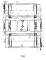
- FIGS. 1 and 2 show a tram motor bogie comprising a chassis 1 resting on four wheels 2 by means of a primary suspension 3 allowing a vertical deflection of the order of +/- 15 mm.
- the four wheels 2 are conventionally distributed according to two running gear each intended to come on a rail of the track, the wheels 2 each having an individual wheel shaft mounted on an axle box and not being interconnected by an axle shaft.
- the chassis 1 comprises a structure consisting mainly of two longitudinal longitudinal members 11 interconnected by two cross members 12, the longitudinal longitudinal members 11 being disposed outside the wheels 2 and extending at a height greater than 1 2.
- the crosspieces 12 extend perpendicularly to the longitudinal longitudinal members 11 and have a lowered central portion, disposed within the zone delimited by the four wheels 2, extending at a height less than the axis. wheels 2 and to release the maximum space between the wheels 2 for the establishment of a floor.
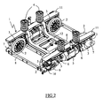
- the longitudinal longitudinal members 11 support, on their upper face, secondary suspension members 4 intended to receive the body of the tramway via a load crossbar, not shown.
- Each longitudinal spar 11 also supports a traction motor 5 which is arranged laterally under the spar 11 so that the axis of the motor 5 is external to the longitudinal plane of the two wheels 2 of the undercarriage.
- These motors 5 comprise a rotor provided with two output shafts, each of the output shafts being connected to the nearest wheel 2 by means of a telescopic transmission 6 with double universal joint, itself connected to a gearbox 7 with bevel gears mounted directly on the shaft of the wheel 2.
- Each gearbox 7 is mounted outside the plane of the wheel 2 and comprises a casing incorporating the axle box of the wheel 2, the casing of the gearbox 7 also serving as a two-member support member of the primary suspension 3 of known type, sandwiched with metal plates and elastomeric material, as can be seen in FIG.
- Secondary cross-members 8 interconnect the gearbox housings 7 of the two undercarriages, these crosspieces 8 being disposed on either side of each wheel 2, at a height that is substantially identical to the height of the lowered central portion of the wheels. cross members 12 of the chassis 1. These secondary cross members 8 maintain the spacing and parallelism between the wheels 2 of the two undercarriages.
- Each undercarriage comprises a wheel 2 comprising a wheel shaft passing through the casing of the gearbox 7 towards the outside of the bogie and having an end secured to a brake disc 9, the latter cooperating with a fixed brake caliper 10 to the longitudinal spar 11 and to the housing of the gearbox 7.
- These braking members constituted by the disc 9 and the stirrup 10, allow braking all of the two wheels 2 of the undercarriage, the latter being mechanically coupled by the rotor common traction motor 5.
- the motor bogie previously described by integrating the axle boxes in the gearbox housings and using these housings as a support element for the primary suspension members, has the advantage of having a space between the wheels completely free up to at the height of the lowered sleepers of the frame, which allows for a low floor having, at the level of the bogies, a width close to the spacing between the wheels.
- axle boxes in the gearbox housings ensures not only reduced space and weight saving, but also frees up space for the installation of brake components outside the gearboxes. wheels, the latter then having the advantage of easy maintenance.
- a braking installation also makes it possible to use brake disks and braking calipers identical to those used on the simply carrying bogies equipping the railway vehicle, which makes it possible to standardize the braking members between the motor bogies and the carrying bogies and therefore to reduce the cost of manufacturing and maintenance of the braking components of the railway vehicle.
- the implementation of a gearbox directly coupled to the wheel and connected to the motor by a telescopic transmission has the advantage of generating a lower torque at the telescopic transmission compared to the torque transmitted by the gearbox to the wheel, which makes it possible to have telescopic transmissions with little space.
- the traction motor with double output shaft of the undercarriages can be replaced by a traction motor with two rotors mechanically independent and arranged one behind the other or two motors of traction.
- each wheel shaft may for example be equipped with a brake disc so as to ensure braking on all four wheels.
Landscapes
- Engineering & Computer Science (AREA)
- Mechanical Engineering (AREA)
- Chemical & Material Sciences (AREA)
- Combustion & Propulsion (AREA)
- Transportation (AREA)
- Arrangement Or Mounting Of Propulsion Units For Vehicles (AREA)
- Vehicle Body Suspensions (AREA)
- Automatic Cycles, And Cycles In General (AREA)
- Platform Screen Doors And Railroad Systems (AREA)
- Electric Propulsion And Braking For Vehicles (AREA)
Description
- L'invention se rapporte à un bogie moteur pour véhicule ferroviaire à plancher bas intégral et plus particulièrement à un bogie comportant un châssis reposant sur quatre roues par l'intermédiaire d'une suspension primaire, le châssis supportant au moins un moteur disposé sur un côté du châssis et relié à au moins une roue par des moyens de transmission.
- L'invention convient notamment aux tramways pour lesquels un plancher bas permet de faciliter l'accès et la sortie aux enfants, personnes âgés et handicapés.
- Il est connu, de la demande de brevet FR 2 637 861 déposée par la demanderesse, un bogie moteur pour véhicule ferroviaire à plancher bas comportant un châssis reposant sur deux essieux par l'intermédiaire d'une suspension primaire, le châssis supportant des moteurs de tractions disposés latéralement sur le bogie et reliés aux roues par des moyens de transmission disposés à l'extérieur des roues. Un tel bogie présente toutefois l'inconvénient de posséder des essieux et des boites d'essieu qui encombrent l'espace entre les roues et obligent donc à disposer le plancher au-dessus des essieux.
- Le document EP-B1-0 698 540 divulgue un bogie moteur pour véhicule ferroviaire à plancher bas comportant un châssis reposant sur quatre roues montées individuellement, sans liaison par arbre d'essieu, et supportant deux moteurs disposés latéralement sur le bogie. Chaque moteur comporte deux arbres de sortie directement reliés à un réducteur disposé à l'extérieur des roues et relié à l'une des roues par un accouplement de type arbre creux autorisant un débattement vertical de la roue. Un tel bogie présente l'avantage de ne pas posséder de liaison par arbre d'essieu entre les roues individuelles, ce qui permet d'abaisser d'avantage le plancher, mais présente toutefois l'inconvénient de comporter des arbres des roues qui sont guidés par des boites d'essieu disposées à l'intérieur des roues, ce qui encombre l'espace à intérieur des roues et limite donc la largeur disponible pour le plancher au niveau des bogies.
- Un tel bogie présente également l'inconvénient de comporter des organes de freinage qui sont placés au niveau des réducteurs et qui sont donc spécifiques au bogie moteur, ce qui conduit à avoir sur un véhicule ferroviaire des organes de freinage qui sont différents sur les bogies moteurs et sur les bogies porteurs ce qui complique les opérations de maintenance.
- Un bogie selon le préambule de la revendication 1 est quant à lui connu du document DE-OS-2910392.
- Un but de la présente invention est donc de remédier à ces différents inconvénients en proposant un bogie moteur pour véhicule ferroviaire à plancher bas intégral qui permette d'avoir un plancher au niveau du bogie s'étendant à une très faible hauteur et sur une largeur proche de l'écartement des roues. Un autre but de la présente invention est de proposer un bogie moteur pour véhicule ferroviaire qui comporte des organes de freinages facilement accessibles et qui puissent indifféremment équiper des bogies porteurs ou moteurs.
- L'invention a pour objet un bogie moteur pour véhicule ferroviaire à plancher bas intégral comportant un châssis reposant sur quatre roues par l'intermédiaire d'une suspension primaire, le châssis supportant au moins un moteur disposé sur un côté du châssis et relié à au moins une roue par des moyens de transmission, que chaque roue comportant un arbre de roue individuel supporté par une boite d'essieu, les moyens de transmission comportant un réducteur couplé directement à l'arbre de la roue et une transmission télescopique, de type à double joint de cardan, disposée entre le réducteur et le moteur, caractérisé en ce que le réducteur est placé à l'extérieur de la roue et comporte un carter intégrant la boite d'essieu de l'arbre de la roue, le carter du réducteur servant également d'élément support à un organe de suspension primaire sur lequel s'appuie le châssis.
- Selon des modes particuliers de réalisation, le bogie moteur selon l'invention peut comprendre l'une ou plusieurs des caractéristiques suivantes prises isolément ou selon toutes les combinaisons techniquement possibles :
- deux moteurs sont fixés sur le châssis et disposés longitudinalement de chaque côté du châssis, chaque moteur entraînant les deux roues, disposées l'une derrière l'autre sur le côté du châssis, au moyen d'une transmission télescopique de type à double joint de cardan placée entre le moteur et un réducteur couplé directement à l'arbre de la roue, chaque réducteur comportant un carter intégrant la boite d'essieu de la roue et servant d'élément support à un organe de suspension primaire ;
- au moins une roue comporte un arbre traversant le carter du réducteur vers l'extérieur du bogie, l'arbre de la roue étant solidaire d'un disque de frein monté à l'extérieur du réducteur ;
- chaque côté du bogie comporte une roue munie d'un arbre traversant le carter du réducteur et solidaire d'un disque de frein, ce dernier étant monté à l'extérieur du réducteur et du coté extérieur à la roue ;
- les moteurs comportent un seul rotor muni de deux arbres de sortie débouchant respectivement sur deux faces opposées ;
- les organes de suspensions primaires sont constitués d'un sandwich de plaques métalliques et de matériau élastomère et sont interposés entre une surface d'appui de la face extérieure des carters des réducteurs et une surface d'appui du châssis ;
- le châssis est constitué de deux longerons longitudinaux disposés à l'extérieur des roues et reliés entre eux par des traverses possédant une partie centrale abaissée s'étendant en dessous du niveau de l'axe des roues.
- On comprendra mieux les buts, aspects et avantages de la présente invention, d'après la description donnée ci-après d'un mode particulier de réalisation de l'invention, présenté à titre d'exemple non limitatif, en se référant aux dessins annexés, dans lesquels :
- la figure 1 est une vue de dessus, d'un bogie moteur pour véhicule ferroviaire à plancher bas selon un mode particulier de réalisation de l'invention ;
- la figure 2 est une vue en perspective du bogie moteur de la figure 1.
- Pour faciliter la lecture du dessin, seuls les éléments nécessaires à la compréhension de l'invention ont été représentés. Les mêmes éléments portent les mêmes références d'une figure à l'autre.
- Les figures 1 et 2 représentent un bogie moteur de tramway comportant un châssis 1 reposant sur quatre roues 2 par l'intermédiaire d'une suspension primaire 3 autorisant un débattement vertical de l'ordre de +/- 15 mm. Les quatre roues 2 sont réparties de manière classique suivant deux trains de roulement destinés chacun à venir sur un rail de la voie ferrée, les roues 2 comportant chacune un arbre de roue individuel monté sur une boite d'essieu et n'étant pas reliées entre elles par un arbre d'essieu.
- Conformément à la figure 2, le châssis 1 comporte une structure constituée principalement par deux longerons longitudinaux 11 reliés entre eux par deux traverses 12, les longerons longitudinaux 11 étant disposés à l'extérieur des roues 2 et s'étendant à une hauteur supérieure à l'axe des roues 2. Les traverses 12 s'étendent perpendiculairement aux longerons longitudinaux 11 et possèdent une partie centrale abaissée, disposée à l'intérieure de la zone délimitée par les quatre roues 2, s'étendant à une hauteur inférieure à l'axe des roues 2 et permettant de libérer le maximum d'espace entre les roues 2 pour la mise en place d'un plancher.
- Les longerons longitudinaux 11 supportent, sur leur face supérieure, des organes de suspensions secondaires 4 destinés à recevoir la caisse du tramway par l'intermédiaire d'une traverse de charge, non représentée.
- Chaque longeron longitudinal 11 supporte également un moteur de traction 5 qui est disposé latéralement sous le longeron 11 de telle sorte que l'axe du moteur 5 soit extérieur au plan longitudinal des deux roues 2 du train de roulement. Ces moteurs 5 comportent un rotor muni de deux arbres de sortie, chacun des arbres de sortie étant relié à la roue 2 la plus proche par l'intermédiaire d'une transmission télescopique 6 à double joint de cardan, elle-même reliée à un réducteur 7 à engrenages coniques monté directement sur l'arbre de la roue 2.
- Chaque réducteur 7 est monté à l'extérieur du plan de la roue 2 et comporte un carter intégrant la boite d'essieu de la roue 2, le carter du réducteur 7 servant également d'élément support à deux organes de la suspension primaire 3 de type connu, en sandwich de plaques métalliques et de matériau élastomère, comme on peut le voir sur la figure 2.
- Des traverses secondaires 8 relient entre eux les carters des réducteurs 7 des deux trains de roulement, ces traverses 8 étant disposées de part et d'autre de chaque roue 2, à une hauteur sensiblement identique à la hauteur de la partie centrale abaissée des traverses 12 du châssis 1. Ces traverses secondaires 8 assurent le maintien de l'écartement et du parallélisme entre les roues 2 des deux trains de roulement.
- Chaque train de roulement comporte une roue 2 comprenant un arbre de roue traversant le carter du réducteur 7 en direction de l'extérieur du bogie et présentant une extrémité solidaire d'un disque de frein 9, ce dernier coopérant avec un étrier de frein 10 fixé au longeron longitudinal 11 et au carter du réducteur 7. Ces organes de freinage, constitués par le disque 9 et l'étrier 10, permettent de freiner l'ensemble des deux roues 2 du train de roulement, ces dernières étant accouplées mécaniquement par le rotor commun du moteur de traction 5.
- Le bogie moteur précédemment décrit, en intégrant les boites d'essieu dans les carters des réducteurs et en utilisant ces carters comme élément d'appui pour les organes de la suspension primaire, présente l'avantage de posséder un espace entre les roues totalement libre jusqu'à hauteur des traverses abaissées du châssis, ce qui permet de réaliser un plancher bas présentant, au niveau des bogies, une largeur proche de l'écartement entre les roues .
- De plus, l'intégration des boites d'essieu dans les carter des réducteurs assure non seulement un encombrement réduit et un gain de masse, mais permet également de libérer de la place pour l'installation d'organes de freinage à l'extérieur des roues, ces derniers présentant alors l'avantage d'une maintenance aisée. Une telle installation de freinage permet aussi d'utiliser des disques de frein et des étriers de freinage identiques à ceux utilisés sur les bogies simplement porteurs équipant le véhicule ferroviaire, ce qui permet de standardiser les organes de freinage entre les bogies moteurs et les bogies porteurs et donc de réduire le coût de fabrication et de maintenance des organes de freinage du véhicule ferroviaire.
- Enfin, l'implantation d'un réducteur directement couplé à la roue et relié au moteur par une transmission télescopique a l'avantage de générer un plus faible couple au niveau de la transmission télescopique par rapport au couple transmis par le réducteur à la roue, ce qui permet d'avoir des transmissions télescopiques peu encombrantes.
- Bien entendu, l'invention n'est nullement limitée au mode de réalisation décrit et illustré qui n'a été donné qu'à titre d'exemple. Des modifications restent possibles, notamment du point de vue de la constitution des divers éléments ou par substitution d'équivalents techniques, sans sortir pour autant du domaine de protection de l'invention.
- Ainsi, dans une variante de réalisation non représentée, le moteur de traction à double arbre de sortie des trains de roulement peut être remplacé par un moteur de traction à deux rotors mécaniquement indépendant et disposés l'un derrière l'autre ou par deux moteurs de traction. Dans un tel cas, chaque arbre de roue peut par exemple être équipé d'un disque de frein de manière à assurer le freinage sur l'ensemble des quatre roues.
Claims (7)
- Bogie moteur pour véhicule ferroviaire à plancher bas intégral comportant un châssis (1) reposant sur quatre roues (2) par l'intermédiaire d'une suspension primaire (3), ledit châssis (1) supportant au moins un moteur (5) disposé sur un côté du châssis (1) et relié à au moins une roue (2) par des moyens de transmission (6,7), chaque roue (2) comportant un arbre de roue individuel supporté par une boite d'essieu, lesdits moyens de transmission comportant un réducteur (7) couplé directement à l'arbre de ladite roue (2) et une transmission télescopique (6) de type à double joint de cardan disposée entre le réducteur (7) et le moteur (5), caractérisé en ce que ledit réducteur (7) est placé à l'extérieur de la roue (2) et comporte un carter intégrant la boite d'essieu de l'arbre de la roue (2), ledit carter du réducteur (7) servant d'élément support à un organe de la suspension primaire (3) sur lequel s'appuie le châssis (1).
- Bogie moteur selon la revendication 1, caractérisé en ce qu'il comporte deux moteurs (5) fixés sur le châssis (1) et disposés longitudinalement de chaque côté du châssis (1), chaque moteur (5) entraînant les deux roues (2), disposées l'une derrière l'autre sur le côté du châssis (1), au moyen d'une transmission télescopique (6) de type à double joint de cardan placée entre le moteur (5) et un réducteur (7) couplé directement à l'arbre de la roue (2), chaque réducteur (7) comportant un carter intégrant la boite d'essieu de la roue (2) et servant d'élément support à un organe de suspension primaire (3).
- Bogie moteur selon l'une quelconque des revendications 1 à 2, caractérisé en ce qu'au moins une roue (2) comporte un arbre traversant le carter du réducteur (7) vers l'extérieur du bogie, ledit arbre de la roue (2) étant solidaire d'un disque de frein (9) monté à l'extérieur du réducteur (7).
- Bogie moteur selon les revendications 2 et 3, caractérise ce que chaque côté du bogie comporte une roue (2) muni d'un arbre traversant le carter du réducteur (7) et solidaire d'un disque de frein (9), ledit disque de frein (9) étant monté à l'extérieur du réducteur (7) et du coté extérieur à la roue (2).
- Bogie moteur selon l'une quelconque des revendications 1 à 4, caractérisé en ce que lesdits moteurs (5) comportent un seul rotor muni de deux arbres de sortie débouchant respectivement sur deux faces opposées.
- Bogie moteur selon l'une quelconque des revendications 1 à 5, caractérisé en ce que lesdits organes de suspensions primaires (3) sont constitués d'un sandwich de plaques métalliques et de matériau élastomère et sont interposés entre une surface d'appui de la face extérieure des carters des réducteurs (7) et une surface d'appui du châssis (1).
- Bogie moteur selon l'une quelconque des revendications 1 à 6, caractérisé en ce que ledit châssis (1) est constitué de deux longerons longitudinaux (11) disposés à l'extérieur des roues (2) et reliés entre eux par des traverses (12) possédant une partie centrale abaissée s'étendant en dessous du niveau de l'axe des roues (2).
Applications Claiming Priority (2)
| Application Number | Priority Date | Filing Date | Title |
|---|---|---|---|
| FR0108425 | 2001-06-26 | ||
| FR0108425A FR2826328B1 (fr) | 2001-06-26 | 2001-06-26 | Bogie moteur pour vehicule ferroviaire a plancher bas integral |
Publications (2)
| Publication Number | Publication Date |
|---|---|
| EP1270359A1 EP1270359A1 (fr) | 2003-01-02 |
| EP1270359B1 true EP1270359B1 (fr) | 2006-12-20 |
Family
ID=8864790
Family Applications (1)
| Application Number | Title | Priority Date | Filing Date |
|---|---|---|---|
| EP02291504A Expired - Lifetime EP1270359B1 (fr) | 2001-06-26 | 2002-06-17 | Bogie moteur pour vehicule ferroviaire a plancher bas integral |
Country Status (9)
| Country | Link |
|---|---|
| US (1) | US6601520B2 (fr) |
| EP (1) | EP1270359B1 (fr) |
| JP (1) | JP3983114B2 (fr) |
| AT (1) | ATE348742T1 (fr) |
| AU (1) | AU779297B2 (fr) |
| CA (1) | CA2391566C (fr) |
| DE (1) | DE60216855T2 (fr) |
| ES (1) | ES2273981T3 (fr) |
| FR (1) | FR2826328B1 (fr) |
Cited By (4)
| Publication number | Priority date | Publication date | Assignee | Title |
|---|---|---|---|---|
| DE102013002096A1 (de) | 2013-02-05 | 2014-08-07 | Josef Staltmeir | Hochgeschwindigkeitszug mit geringem Energieumsatz |
| EP3159236B1 (fr) | 2015-10-23 | 2019-03-20 | ALSTOM Transport Technologies | Véhicule ferroviaire comprenant au moins un bogie abaissé |
| CN110843841A (zh) * | 2019-11-27 | 2020-02-28 | 衡阳市利美电瓶车制造有限责任公司 | 一种有轨电动平车 |
| RU2715669C2 (ru) * | 2015-10-23 | 2020-03-02 | Альстом Транспорт Текнолоджис | Тележка для полностью двухэтажного железнодорожного транспортного средства |
Families Citing this family (30)
| Publication number | Priority date | Publication date | Assignee | Title |
|---|---|---|---|---|
| AT504310B1 (de) * | 2004-07-16 | 2011-04-15 | Siemens Ag Oesterreich | Schienenfahrzeug mit einem drehzapfenlosen fahrwerk |
| DE102004054917A1 (de) * | 2004-11-09 | 2006-05-11 | Henschel Antriebstechnik Gmbh | Getriebe für ein Schienenfahrzeug, insbesondere ein Niederflurfahrzeug, und damit ausgerüstetes Schienenfahrzeug |
| CN100383003C (zh) * | 2005-07-01 | 2008-04-23 | 李孝龙 | 低地高速列车 |
| FR2896751B1 (fr) * | 2006-01-30 | 2008-04-18 | Alstom Transport Sa | Essieu pour vehicule ferroviaire a plancher bas, bogie et vehicule ferroviaire correspondant. |
| JP4874718B2 (ja) * | 2006-06-19 | 2012-02-15 | 株式会社東芝 | 電気車駆動装置 |
| CZ307181B6 (cs) * | 2006-09-18 | 2018-02-28 | Miroslav KaluĹľa | Podvozek kolejového vozidla |
| JP4979374B2 (ja) * | 2006-12-28 | 2012-07-18 | 川崎重工業株式会社 | 低床式鉄道車両用台車 |
| FR2914607B1 (fr) | 2007-04-05 | 2014-03-28 | Alstom Transport Sa | Bogie motorise pour tramway |
| FR2914609B1 (fr) * | 2007-04-05 | 2009-07-10 | Alstom Transport Sa | Bogie pour vehicule ferroviaire |
| FR2914608B1 (fr) | 2007-04-06 | 2009-06-26 | Alstom Transport Sa | Bogie pour vehicule ferroviaire |
| EP2216227B1 (fr) * | 2007-11-16 | 2016-05-18 | Kawasaki Jukogyo Kabushiki Kaisha | Bogie pour véhicule ferroviaire de type à plancher surbaissé et véhicule ferroviaire de type à plancher surbaissé utilisant le bogie |
| JP4685921B2 (ja) * | 2008-12-26 | 2011-05-18 | 株式会社日立製作所 | 鉄道車両用台車 |
| JP5010629B2 (ja) * | 2009-02-20 | 2012-08-29 | 三菱重工業株式会社 | 低床式車両 |
| JP5010630B2 (ja) * | 2009-02-20 | 2012-08-29 | 三菱重工業株式会社 | 低床式車両 |
| US8720346B2 (en) * | 2010-02-15 | 2014-05-13 | Nippon Sharyo, Ltd. | Bogie frame for railroad vehicle |
| CN101979266B (zh) * | 2010-10-26 | 2012-01-18 | 长春轨道客车股份有限公司 | 100%低地板轻轨车独立轮动力转向架 |
| CN101992791B (zh) * | 2010-10-26 | 2012-09-05 | 长春轨道客车股份有限公司 | 100%低地板轻轨车独立轮拖车转向架 |
| CN103072590A (zh) * | 2011-10-26 | 2013-05-01 | 同济大学 | 一种低地板车悬挂式转向架 |
| TR201113211A2 (tr) | 2011-12-29 | 2012-12-21 | Durmazlar Mak�Na Sanay� Ve T�Caret Anon�M ��Rket� | Yeni bir tip süspansiyon sistemine sahip çift parçalı boji. |
| CN102582645B (zh) * | 2012-02-12 | 2015-07-01 | 株洲时代电子技术有限公司 | 一种轨道工程车辆用电传动转向架 |
| JP5869403B2 (ja) * | 2012-03-30 | 2016-02-24 | 株式会社総合車両製作所 | 鉄道車両用台車及びその製造方法 |
| CZ305145B6 (cs) * | 2013-06-26 | 2015-05-20 | Západočeská Univerzita V Plzni | Trakční podvozek pro kolejová vozidla |
| DE102014215201A1 (de) * | 2014-08-01 | 2016-02-04 | Zf Friedrichshafen Ag | Einzelradantrieb für ein Schienenfahrzeug |
| CN104442883A (zh) * | 2014-12-05 | 2015-03-25 | 长春轨道客车股份有限公司 | 一种100%低地板轻轨车辆用无动力转向架 |
| FR3029879B1 (fr) * | 2014-12-15 | 2017-01-13 | Alstom Transp Tech | Bogie motorise pour un vehicule ferroviaire a plancher surbaisse |
| DE102015211064A1 (de) * | 2015-06-16 | 2016-12-22 | Bombardier Transportation Gmbh | Antriebsanordnung für Schienenfahrzeug, Schienenfahrzeug mit Antriebsanordnung sowie Verfahren zum Herstellen der Antriebsanordnung und des Schienenfahrzeugs |
| FR3047715B1 (fr) | 2016-02-11 | 2019-06-21 | Alstom Transport Technologies | Vehicule ferroviaire comprenant deux voitures et un passage d'interconnexion comprenant chacun deux niveaux |
| IT201600088005A1 (it) | 2016-08-30 | 2018-03-02 | Lucchini Rs Spa | Ponte-assale di veicoli ferroviari e ferrotranviari a pianale ribassato |
| FR3064238B1 (fr) * | 2017-03-22 | 2020-08-28 | Alstom Transp Tech | Bogie de vehicule ferroviaire comprenant des essieux fixes rigidement au chassis du bogie |
| CN119928933A (zh) * | 2025-02-21 | 2025-05-06 | 中车株洲电力机车有限公司 | 一种低地板转向架和轨道车辆 |
Family Cites Families (16)
| Publication number | Priority date | Publication date | Assignee | Title |
|---|---|---|---|---|
| US452035A (en) * | 1891-05-12 | short | ||
| US1880953A (en) * | 1929-02-13 | 1932-10-04 | Twin Coach Co | Rail car construction |
| DE2514265C3 (de) * | 1975-03-27 | 1979-06-13 | Siemens Ag, 1000 Berlin Und 8000 Muenchen | Antrieb für ein elektrisches Schienenfahrzeug |
| US4135456A (en) * | 1977-05-26 | 1979-01-23 | Pullman Incorporated | Powered railway car steering assembly |
| DE2910392A1 (de) * | 1979-03-16 | 1980-09-25 | Thyssen Industrie | Drehgestell fuer schienenfahrzeuge, insbesondere fuer strassenbahnen o.dgl. |
| US4648326A (en) * | 1985-02-22 | 1987-03-10 | Lukens General Industries, Inc. | Radial axle railway truck with axle couplings at sides transversely interconnected with each other |
| FR2637861B1 (fr) | 1988-10-18 | 1991-04-26 | Alsthom Gec | Bogie moteur pour vehicule ferroviaire a plancher bas sur toute sa longueur |
| US5277127A (en) * | 1989-08-21 | 1994-01-11 | Sig Schweizerische Industrie Gesellschaft | Driven running gear with steerable individual units |
| IT219394Z2 (it) * | 1990-03-13 | 1993-02-26 | Carrello motorizzato a ruote indipendenti per veicoli a pianale ribassato | |
| FR2664222B1 (fr) * | 1990-07-05 | 1993-01-15 | Alsthom Gec | Bogie a roues independantes motorisees pour vehicule ferroviaire. |
| DE4414293C1 (de) * | 1994-04-23 | 1995-09-14 | Duewag Ag | Fahrwerk für Schienenfahrzeuge |
| DE4419362A1 (de) * | 1994-06-03 | 1995-12-07 | Bergische Stahlindustrie | Niederflur-Gelenktriebwagen, insbesondere für den Personenverkehr auf innerstädtischen Schienennetzen |
| DE4429889A1 (de) | 1994-08-24 | 1996-02-29 | Bergische Stahlindustrie | Angetriebenes Fahrwerk für Schienenfahrzeuge |
| AT406569B (de) * | 1995-03-23 | 2000-06-26 | Elin Ebg Traction Gmbh | Fahrwerk für ein schienenfahrzeug, insbesondere niederflurstrassenbahn |
| DE19650913A1 (de) * | 1996-12-07 | 1998-06-10 | Sab Wabco Bsi Verkehrstechnik | Angetriebene Losradachse |
| US6267062B1 (en) * | 1998-03-30 | 2001-07-31 | Hugh B. Hamilton, Jr. | AC drive industrial switching locomotive |
-
2001
- 2001-06-26 FR FR0108425A patent/FR2826328B1/fr not_active Expired - Fee Related
-
2002
- 2002-06-17 ES ES02291504T patent/ES2273981T3/es not_active Expired - Lifetime
- 2002-06-17 EP EP02291504A patent/EP1270359B1/fr not_active Expired - Lifetime
- 2002-06-17 DE DE60216855T patent/DE60216855T2/de not_active Expired - Lifetime
- 2002-06-17 AT AT02291504T patent/ATE348742T1/de active
- 2002-06-20 US US10/175,457 patent/US6601520B2/en not_active Expired - Lifetime
- 2002-06-24 AU AU48919/02A patent/AU779297B2/en not_active Ceased
- 2002-06-24 JP JP2002182447A patent/JP3983114B2/ja not_active Expired - Lifetime
- 2002-06-25 CA CA002391566A patent/CA2391566C/fr not_active Expired - Fee Related
Cited By (5)
| Publication number | Priority date | Publication date | Assignee | Title |
|---|---|---|---|---|
| DE102013002096A1 (de) | 2013-02-05 | 2014-08-07 | Josef Staltmeir | Hochgeschwindigkeitszug mit geringem Energieumsatz |
| EP3159236B1 (fr) | 2015-10-23 | 2019-03-20 | ALSTOM Transport Technologies | Véhicule ferroviaire comprenant au moins un bogie abaissé |
| RU2715669C2 (ru) * | 2015-10-23 | 2020-03-02 | Альстом Транспорт Текнолоджис | Тележка для полностью двухэтажного железнодорожного транспортного средства |
| CN110843841A (zh) * | 2019-11-27 | 2020-02-28 | 衡阳市利美电瓶车制造有限责任公司 | 一种有轨电动平车 |
| CN110843841B (zh) * | 2019-11-27 | 2021-08-03 | 湖南利美防爆装备制造股份有限公司 | 一种有轨电动平车 |
Also Published As
| Publication number | Publication date |
|---|---|
| JP3983114B2 (ja) | 2007-09-26 |
| US6601520B2 (en) | 2003-08-05 |
| AU4891902A (en) | 2003-01-02 |
| ATE348742T1 (de) | 2007-01-15 |
| FR2826328B1 (fr) | 2003-08-29 |
| CA2391566C (fr) | 2008-08-12 |
| ES2273981T3 (es) | 2007-05-16 |
| CA2391566A1 (fr) | 2002-12-26 |
| AU779297B2 (en) | 2005-01-13 |
| EP1270359A1 (fr) | 2003-01-02 |
| DE60216855T2 (de) | 2007-08-30 |
| FR2826328A1 (fr) | 2002-12-27 |
| US20020195018A1 (en) | 2002-12-26 |
| JP2003025989A (ja) | 2003-01-29 |
| DE60216855D1 (de) | 2007-02-01 |
Similar Documents
| Publication | Publication Date | Title |
|---|---|---|
| EP1270359B1 (fr) | Bogie moteur pour vehicule ferroviaire a plancher bas integral | |
| CA2683119C (fr) | Vehicule ferroviaire comprenant des bogies d'extremite pivotants | |
| EP3650304B1 (fr) | Bogie pour véhicule ferroviaire | |
| EP3159237B1 (fr) | Véhicule ferroviaire comprenant au moins un bogie abaissé | |
| EP1826092A1 (fr) | Essieu pour véhicule ferroviaire à plancher bas, bogie et véhicule ferroviaire comprenants un tel essieu | |
| EP1977949B1 (fr) | Bogie pour véhicule ferroviaire | |
| EP3159236B2 (fr) | Véhicule ferroviaire comprenant au moins un bogie abaissé | |
| EP3222483A1 (fr) | Bogie à moteur extérieur et véhicule ferroviaire associé | |
| EP0829413A2 (fr) | Bogie orientable | |
| CA2000750C (fr) | Bogie moteur pour vehicule ferroviaire a plancher bas sur toute sa longueur | |
| EP0834435A1 (fr) | Châssis de bogie articulé et bogie articulé comportant un tel châssis | |
| EP3854655B1 (fr) | Bogie pour véhicule à roues indépendantes et véhicule associé | |
| EP0630799B1 (fr) | Train de roulement pour véhicule circulant sur une voie de guidage | |
| EP4074572B1 (fr) | Bogie moteur de véhicule ferroviaire | |
| FR3076792A1 (fr) | Bogie pour vehicule ferroviaire | |
| BE898075A (fr) | Bogie a deux essieux pour vehicules ferroviaires ou tramways et vehicules ferroviaires ou tramways utilisant ce bogie. | |
| EP3521129B1 (fr) | Bogie et véhicule ferroviaire associé | |
| EP1067034B1 (fr) | Equipement ferroviaire roulant notamment pour le transport de vehicules routiers lourds | |
| FR2491850A1 (fr) | Bogie de chemin de fer autodirecteur |
Legal Events
| Date | Code | Title | Description |
|---|---|---|---|
| PUAI | Public reference made under article 153(3) epc to a published international application that has entered the european phase |
Free format text: ORIGINAL CODE: 0009012 |
|
| AK | Designated contracting states |
Kind code of ref document: A1 Designated state(s): AT BE CH CY DE DK ES FI FR GB GR IE IT LI LU MC NL PT SE TR |
|
| AX | Request for extension of the european patent |
Free format text: AL;LT;LV;MK;RO;SI |
|
| 17P | Request for examination filed |
Effective date: 20030702 |
|
| AKX | Designation fees paid |
Designated state(s): AT BE CH CY DE DK ES FI FR GB GR IE IT LI LU MC NL PT SE TR |
|
| RAP1 | Party data changed (applicant data changed or rights of an application transferred) |
Owner name: ALSTOM |
|
| GRAP | Despatch of communication of intention to grant a patent |
Free format text: ORIGINAL CODE: EPIDOSNIGR1 |
|
| GRAS | Grant fee paid |
Free format text: ORIGINAL CODE: EPIDOSNIGR3 |
|
| GRAA | (expected) grant |
Free format text: ORIGINAL CODE: 0009210 |
|
| AK | Designated contracting states |
Kind code of ref document: B1 Designated state(s): AT BE CH CY DE DK ES FI FR GB GR IE IT LI LU MC NL PT SE TR |
|
| PG25 | Lapsed in a contracting state [announced via postgrant information from national office to epo] |
Ref country code: IE Free format text: LAPSE BECAUSE OF FAILURE TO SUBMIT A TRANSLATION OF THE DESCRIPTION OR TO PAY THE FEE WITHIN THE PRESCRIBED TIME-LIMIT Effective date: 20061220 Ref country code: DK Free format text: LAPSE BECAUSE OF FAILURE TO SUBMIT A TRANSLATION OF THE DESCRIPTION OR TO PAY THE FEE WITHIN THE PRESCRIBED TIME-LIMIT Effective date: 20061220 Ref country code: FI Free format text: LAPSE BECAUSE OF FAILURE TO SUBMIT A TRANSLATION OF THE DESCRIPTION OR TO PAY THE FEE WITHIN THE PRESCRIBED TIME-LIMIT Effective date: 20061220 |
|
| REG | Reference to a national code |
Ref country code: GB Ref legal event code: FG4D Free format text: NOT ENGLISH |
|
| RIN1 | Information on inventor provided before grant (corrected) |
Inventor name: LOISEAU, JEAN-CHRISTOPHE Inventor name: ECHE, CHRISTOPHE Inventor name: RODET, ALAIN |
|
| REG | Reference to a national code |
Ref country code: CH Ref legal event code: EP |
|
| REF | Corresponds to: |
Ref document number: 60216855 Country of ref document: DE Date of ref document: 20070201 Kind code of ref document: P |
|
| REG | Reference to a national code |
Ref country code: IE Ref legal event code: FG4D Free format text: LANGUAGE OF EP DOCUMENT: FRENCH |
|
| GBT | Gb: translation of ep patent filed (gb section 77(6)(a)/1977) |
Effective date: 20070130 |
|
| REG | Reference to a national code |
Ref country code: SE Ref legal event code: TRGR |
|
| PG25 | Lapsed in a contracting state [announced via postgrant information from national office to epo] |
Ref country code: PT Free format text: LAPSE BECAUSE OF FAILURE TO SUBMIT A TRANSLATION OF THE DESCRIPTION OR TO PAY THE FEE WITHIN THE PRESCRIBED TIME-LIMIT Effective date: 20070423 |
|
| REG | Reference to a national code |
Ref country code: ES Ref legal event code: FG2A Ref document number: 2273981 Country of ref document: ES Kind code of ref document: T3 |
|
| PLBI | Opposition filed |
Free format text: ORIGINAL CODE: 0009260 |
|
| PLAX | Notice of opposition and request to file observation + time limit sent |
Free format text: ORIGINAL CODE: EPIDOSNOBS2 |
|
| 26 | Opposition filed |
Opponent name: BOMBARDIER TRANSPORTATION GMBH Effective date: 20070920 |
|
| NLR1 | Nl: opposition has been filed with the epo |
Opponent name: BOMBARDIER TRANSPORTATION GMBH |
|
| PLAF | Information modified related to communication of a notice of opposition and request to file observations + time limit |
Free format text: ORIGINAL CODE: EPIDOSCOBS2 |
|
| PG25 | Lapsed in a contracting state [announced via postgrant information from national office to epo] |
Ref country code: MC Free format text: LAPSE BECAUSE OF NON-PAYMENT OF DUE FEES Effective date: 20070630 |
|
| PG25 | Lapsed in a contracting state [announced via postgrant information from national office to epo] |
Ref country code: GR Free format text: LAPSE BECAUSE OF FAILURE TO SUBMIT A TRANSLATION OF THE DESCRIPTION OR TO PAY THE FEE WITHIN THE PRESCRIBED TIME-LIMIT Effective date: 20070321 |
|
| PLBB | Reply of patent proprietor to notice(s) of opposition received |
Free format text: ORIGINAL CODE: EPIDOSNOBS3 |
|
| PG25 | Lapsed in a contracting state [announced via postgrant information from national office to epo] |
Ref country code: LU Free format text: LAPSE BECAUSE OF NON-PAYMENT OF DUE FEES Effective date: 20070617 Ref country code: CY Free format text: LAPSE BECAUSE OF FAILURE TO SUBMIT A TRANSLATION OF THE DESCRIPTION OR TO PAY THE FEE WITHIN THE PRESCRIBED TIME-LIMIT Effective date: 20061220 |
|
| PG25 | Lapsed in a contracting state [announced via postgrant information from national office to epo] |
Ref country code: TR Free format text: LAPSE BECAUSE OF FAILURE TO SUBMIT A TRANSLATION OF THE DESCRIPTION OR TO PAY THE FEE WITHIN THE PRESCRIBED TIME-LIMIT Effective date: 20061220 |
|
| RAP2 | Party data changed (patent owner data changed or rights of a patent transferred) |
Owner name: ALSTOM TRANSPORT SA |
|
| NLT2 | Nl: modifications (of names), taken from the european patent patent bulletin |
Owner name: ALSTOM TRANSPORT SA Effective date: 20091104 |
|
| PLCK | Communication despatched that opposition was rejected |
Free format text: ORIGINAL CODE: EPIDOSNREJ1 |
|
| APAH | Appeal reference modified |
Free format text: ORIGINAL CODE: EPIDOSCREFNO |
|
| APBM | Appeal reference recorded |
Free format text: ORIGINAL CODE: EPIDOSNREFNO |
|
| APBP | Date of receipt of notice of appeal recorded |
Free format text: ORIGINAL CODE: EPIDOSNNOA2O |
|
| APBQ | Date of receipt of statement of grounds of appeal recorded |
Free format text: ORIGINAL CODE: EPIDOSNNOA3O |
|
| APBC | Information on closure of appeal procedure deleted |
Free format text: ORIGINAL CODE: EPIDOSDNOA9O |
|
| APBU | Appeal procedure closed |
Free format text: ORIGINAL CODE: EPIDOSNNOA9O |
|
| APAN | Information on closure of appeal procedure modified |
Free format text: ORIGINAL CODE: EPIDOSCNOA9O |
|
| APBU | Appeal procedure closed |
Free format text: ORIGINAL CODE: EPIDOSNNOA9O |
|
| PLBN | Opposition rejected |
Free format text: ORIGINAL CODE: 0009273 |
|
| STAA | Information on the status of an ep patent application or granted ep patent |
Free format text: STATUS: OPPOSITION REJECTED |
|
| 27O | Opposition rejected |
Effective date: 20130716 |
|
| REG | Reference to a national code |
Ref country code: DE Ref legal event code: R100 Ref document number: 60216855 Country of ref document: DE Effective date: 20130716 |
|
| REG | Reference to a national code |
Ref country code: FR Ref legal event code: TP Owner name: ALSTOM TRANSPORT TECHNOLOGIES, FR Effective date: 20141209 |
|
| REG | Reference to a national code |
Ref country code: CH Ref legal event code: PUE Owner name: ALSTOM TRANSPORT SA, FR Free format text: FORMER OWNER: ALSTOM, FR Ref country code: CH Ref legal event code: PUE Owner name: ALSTOM TRANSPORT TECHNOLOGIES, FR Free format text: FORMER OWNER: ALSTOM TRANSPORT SA, FR |
|
| REG | Reference to a national code |
Ref country code: DE Ref legal event code: R082 Ref document number: 60216855 Country of ref document: DE Representative=s name: DREISS PATENTANWAELTE PARTG MBB, DE Ref country code: DE Ref legal event code: R081 Ref document number: 60216855 Country of ref document: DE Owner name: ALSTOM TRANSPORT TECHNOLOGIES, FR Free format text: FORMER OWNER: ALSTOM, LEVALLOIS-PERRET, FR |
|
| REG | Reference to a national code |
Ref country code: GB Ref legal event code: 732E Free format text: REGISTERED BETWEEN 20151001 AND 20151007 |
|
| REG | Reference to a national code |
Ref country code: GB Ref legal event code: 732E Free format text: REGISTERED BETWEEN 20151119 AND 20151125 |
|
| REG | Reference to a national code |
Ref country code: FR Ref legal event code: PLFP Year of fee payment: 15 |
|
| REG | Reference to a national code |
Ref country code: FR Ref legal event code: PLFP Year of fee payment: 16 |
|
| REG | Reference to a national code |
Ref country code: DE Ref legal event code: R082 Ref document number: 60216855 Country of ref document: DE Representative=s name: DREISS PATENTANWAELTE PARTG MBB, DE Ref country code: DE Ref legal event code: R081 Ref document number: 60216855 Country of ref document: DE Owner name: ALSTOM TRANSPORT TECHNOLOGIES, FR Free format text: FORMER OWNER: ALSTOM TRANSPORT TECHNOLOGIES, LEVALLOIS-PERRET, FR |
|
| REG | Reference to a national code |
Ref country code: CH Ref legal event code: NV Representative=s name: BUGNION S.A., CH Ref country code: CH Ref legal event code: PCOW Free format text: NEW ADDRESS: 48 RUE ALBERT DHALENNE, 93400 SAINT-OUEN (FR) |
|
| REG | Reference to a national code |
Ref country code: FR Ref legal event code: CA Effective date: 20180103 |
|
| REG | Reference to a national code |
Ref country code: AT Ref legal event code: PC Ref document number: 348742 Country of ref document: AT Kind code of ref document: T Owner name: ALSTOM TRANSPORT TECHNOLOGIES, FR Effective date: 20180220 |
|
| REG | Reference to a national code |
Ref country code: FR Ref legal event code: PLFP Year of fee payment: 17 |
|
| PGFP | Annual fee paid to national office [announced via postgrant information from national office to epo] |
Ref country code: SE Payment date: 20190619 Year of fee payment: 18 |
|
| PGFP | Annual fee paid to national office [announced via postgrant information from national office to epo] |
Ref country code: GB Payment date: 20190619 Year of fee payment: 18 |
|
| PGFP | Annual fee paid to national office [announced via postgrant information from national office to epo] |
Ref country code: CH Payment date: 20200618 Year of fee payment: 19 |
|
| PGFP | Annual fee paid to national office [announced via postgrant information from national office to epo] |
Ref country code: AT Payment date: 20200619 Year of fee payment: 19 |
|
| PGFP | Annual fee paid to national office [announced via postgrant information from national office to epo] |
Ref country code: ES Payment date: 20200824 Year of fee payment: 19 |
|
| PGFP | Annual fee paid to national office [announced via postgrant information from national office to epo] |
Ref country code: IT Payment date: 20200625 Year of fee payment: 19 |
|
| GBPC | Gb: european patent ceased through non-payment of renewal fee |
Effective date: 20200617 |
|
| REG | Reference to a national code |
Ref country code: BE Ref legal event code: MM Effective date: 20200630 |
|
| PG25 | Lapsed in a contracting state [announced via postgrant information from national office to epo] |
Ref country code: GB Free format text: LAPSE BECAUSE OF NON-PAYMENT OF DUE FEES Effective date: 20200617 |
|
| PG25 | Lapsed in a contracting state [announced via postgrant information from national office to epo] |
Ref country code: SE Free format text: LAPSE BECAUSE OF NON-PAYMENT OF DUE FEES Effective date: 20200618 Ref country code: BE Free format text: LAPSE BECAUSE OF NON-PAYMENT OF DUE FEES Effective date: 20200630 |
|
| PGFP | Annual fee paid to national office [announced via postgrant information from national office to epo] |
Ref country code: NL Payment date: 20210618 Year of fee payment: 20 Ref country code: FR Payment date: 20210622 Year of fee payment: 20 Ref country code: DE Payment date: 20210618 Year of fee payment: 20 |
|
| REG | Reference to a national code |
Ref country code: SE Ref legal event code: EUG |
|
| REG | Reference to a national code |
Ref country code: CH Ref legal event code: PL |
|
| REG | Reference to a national code |
Ref country code: AT Ref legal event code: MM01 Ref document number: 348742 Country of ref document: AT Kind code of ref document: T Effective date: 20210617 |
|
| PG25 | Lapsed in a contracting state [announced via postgrant information from national office to epo] |
Ref country code: LI Free format text: LAPSE BECAUSE OF NON-PAYMENT OF DUE FEES Effective date: 20210630 Ref country code: CH Free format text: LAPSE BECAUSE OF NON-PAYMENT OF DUE FEES Effective date: 20210630 Ref country code: AT Free format text: LAPSE BECAUSE OF NON-PAYMENT OF DUE FEES Effective date: 20210617 |
|
| REG | Reference to a national code |
Ref country code: DE Ref legal event code: R071 Ref document number: 60216855 Country of ref document: DE |
|
| REG | Reference to a national code |
Ref country code: NL Ref legal event code: MK Effective date: 20220616 |
|
| PG25 | Lapsed in a contracting state [announced via postgrant information from national office to epo] |
Ref country code: IT Free format text: LAPSE BECAUSE OF NON-PAYMENT OF DUE FEES Effective date: 20210617 |
|
| REG | Reference to a national code |
Ref country code: ES Ref legal event code: FD2A Effective date: 20220805 |
|
| PG25 | Lapsed in a contracting state [announced via postgrant information from national office to epo] |
Ref country code: ES Free format text: LAPSE BECAUSE OF NON-PAYMENT OF DUE FEES Effective date: 20210618 |