EP1270220A2 - Wechseleinrichtung für Walzen und Zylinder in einer Druckmaschine - Google Patents
Wechseleinrichtung für Walzen und Zylinder in einer Druckmaschine Download PDFInfo
- Publication number
- EP1270220A2 EP1270220A2 EP02020263A EP02020263A EP1270220A2 EP 1270220 A2 EP1270220 A2 EP 1270220A2 EP 02020263 A EP02020263 A EP 02020263A EP 02020263 A EP02020263 A EP 02020263A EP 1270220 A2 EP1270220 A2 EP 1270220A2
- Authority
- EP
- European Patent Office
- Prior art keywords
- unit
- cylinders
- rollers
- printing
- roller support
- Prior art date
- Legal status (The legal status is an assumption and is not a legal conclusion. Google has not performed a legal analysis and makes no representation as to the accuracy of the status listed.)
- Granted
Links
Images

Classifications
-
- B—PERFORMING OPERATIONS; TRANSPORTING
- B41—PRINTING; LINING MACHINES; TYPEWRITERS; STAMPS
- B41F—PRINTING MACHINES OR PRESSES
- B41F13/00—Common details of rotary presses or machines
- B41F13/08—Cylinders
- B41F13/24—Cylinder-tripping devices; Cylinder-impression adjustments
- B41F13/26—Arrangement of cylinder bearings
- B41F13/32—Bearings mounted on swinging supports
-
- B—PERFORMING OPERATIONS; TRANSPORTING
- B41—PRINTING; LINING MACHINES; TYPEWRITERS; STAMPS
- B41F—PRINTING MACHINES OR PRESSES
- B41F13/00—Common details of rotary presses or machines
- B41F13/08—Cylinders
- B41F13/24—Cylinder-tripping devices; Cylinder-impression adjustments
- B41F13/26—Arrangement of cylinder bearings
- B41F13/30—Bearings mounted on sliding supports
-
- B—PERFORMING OPERATIONS; TRANSPORTING
- B41—PRINTING; LINING MACHINES; TYPEWRITERS; STAMPS
- B41F—PRINTING MACHINES OR PRESSES
- B41F23/00—Devices for treating the surfaces of sheets, webs, or other articles in connection with printing
- B41F23/08—Print finishing devices, e.g. for glossing prints
-
- B—PERFORMING OPERATIONS; TRANSPORTING
- B41—PRINTING; LINING MACHINES; TYPEWRITERS; STAMPS
- B41P—INDEXING SCHEME RELATING TO PRINTING, LINING MACHINES, TYPEWRITERS, AND TO STAMPS
- B41P2213/00—Arrangements for actuating or driving printing presses; Auxiliary devices or processes
- B41P2213/80—Means enabling or facilitating exchange of cylinders
Definitions
- the invention relates to a changing device for rollers and Cylinder in a printing press according to the preamble of Claim 1.
- a roller changing device is known from DE 42 04 472 C2.
- the device comprises a handling device, which is arranged on a movable machine table, and furthermore a roller carrier unit, which - with the machine table or separately from the machine table - can be brought into functional connection with the handling device at least when the device handles the rollers and the carrier unit picks up the rollers ,
- the handling device is formed by swivel arms and the roller carrier unit has areas for receiving the rollers that are to be changed as well as the rollers that have been changed.
- a control unit is provided for controlling the operating sequence of the swivel arms.
- the disadvantage here is the relatively large outlay and the fact that use is limited due to the often limited space available on the printing presses.
- the Forme cylinder can be used in a bearing of the printing press and is removable again. There is a removal order for this to remove the forme cylinder from its storage intended.
- the invention has for its object a changing device of the kind described in the introduction to create the avoids disadvantages mentioned, in particular with little machine allowed and improved handling allowed.
- rollers and / or cylinders are known on printing machines to be exchanged periodically. For example, this is the Case when the surface quality of a rubber roller changes deteriorated. There is also an exchange of grid Rolls required if different requirements apply the scooping volume of these rollers is available. Alternatives are Interchangeable cylinders, e.g. around cylinders with different Surface properties or different printing forms use.
- a first advantage of the invention is based on the fact that the changing device can be operated manually or by means of a handling device. Another advantage is that the changeover times can be significantly reduced by arranging the changing device preferably above a printing unit and / or coating unit within a printing press. It is also advantageous that no further storage devices are required outside the printing press and the rollers or cylinders are available directly at the place of use.
- Each printing unit 1 consists in a known manner from a pressure cylinder 11 as Sheet guide cylinder, a blanket cylinder 9, one Plate cylinder 8 and an inking unit. If necessary, that is Plate cylinder 8 assigned a dampening system.
- Each coating unit 2, 3 consists of a printing cylinder 11 as Sheet guide cylinder, a forme cylinder 12 and a metering system 13 or 14.
- the metering system 13 from an application roller 16 and an associated chamber doctor blade 15, on the other hand, the metering system 14 consists of a two-roll mill with paint supply in the nip.
- Alternatives are other dosing systems, e.g. et al with a scoop roller, used.
- the printing units 1 and the coating units 2, 3 are by means of transfer drums 10 as a sheet guide cylinder with each other in Functional connection, as is the case with printing presses in series is known.
- the last coating unit 3 is a boom 5 downstream, which for the purpose of storing the sheet material a boom stack 6 with a circulating conveyor system 7 Has gripper systems.
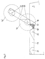
- the changing device is preferred executed for the roll change according to Figure 2.
- the roller support unit 19 is in a side frame of the coating unit 3 fixed in a swivel joint 17 and closes Not used (inactive position) preferably with the top edge the side frames horizontally.
- the roller carrier unit 19 thus assumes a horizontal (inactive) position or an active position at an obtuse angle to the horizontal upper edge of the printing unit 1 or coating unit 2, 3.
- the roller support unit 19 can be pivoted on both sides about the pivot point of the swivel joint 17 in such a way that the roller support unit 19 can be positioned and fixed in an obtuse angle.
- a latching device 18 is provided, which locks the roller support unit 19 (obtuse angle) in one position. In the position 18 '(swiveled-in roller carrier unit 19), the latching device 18 can also be locked or is not active. No further attachment or adjustment means should be discussed in detail.
- Each roller support unit 19 has first bearings 20 arranged in alignment with one another and preferably at least second bearings 21, into which further rollers 16 (or cylinders 12, 9, 8) can be inserted alternately.
Landscapes
- Engineering & Computer Science (AREA)
- Mechanical Engineering (AREA)
- Rotary Presses (AREA)
- Inking, Control Or Cleaning Of Printing Machines (AREA)
- Coating Apparatus (AREA)
Abstract
Description
Von Nachteil ist hierbei, der relativ große Aufwand und dass ein Einsatz aufgrund der häufig beengten Platzverhältnisse an den Druckmaschinen begrenzt ist.
Weiterhin ist von Vorteil, dass durch die Anordnung der Wechseleinrichtung vorzugsweise oberhalb eines Druckwerkes und/oder Lackwerkes innerhalb einer Druckmaschine die Umrüstzeiten deutlich verkürzbar sind.
Ebenso ist vorteilhaft, dass keine weiteren Ablagevorrichtungen außerhalb der Druckmaschine erforderlich sind und die Walzen bzw. Zylinder direkt am Einsatzort vorrätig sind.
- Fig. 1
- eine Offsetdruckmaschine mit zwei Lackierwerken,
- Fig. 2
- eine Walzenablage als Wechseleinrichtung.
In der Position 18' (eingeschwenkte Walzenträgereinheit 19) ist die Rasteinrichtung 18 ebenfalls verriegelbar oder ist nicht aktiv. Auf weitere Anschlag- oder Justiermittel soll nicht näher eingegangen werden. Jede Walzenträgereinheit 19 weist zueinander fluchtend angeordnete erste Lagerungen 20 sowie bevorzugt wenigstens zweite Lagerungen 21 auf, in die weitere Walzen 16 (oder Zylinder 12,9,8) wechselseitig einsetzbar sind.
- 1
- Druckwerk
- 2
- erstes Lackwerk
- 3
- zweites Lackwerk
- 4
- Trocknersystem
- 5
- Ausleger
- 6
- Auslegerstapel
- 7
- Fördersystem
- 8
- Plattenzylinder
- 9
- Gummituchzylinder
- 10
- Transfertrommel
- 11
- Druckzylinder
- 12
- Formzylinder
- 13
- Dosiersystem
- 14
- Dosiersystem
- 15
- Kammerrakel
- 16
- Auftragwalze
- 17
- Drehgelenk
- 18
- Rasteinrichtung
- 19
- Walzenträgereinheit
- 20
- erste Lagerung
- 21
- zweite Lagerung
Claims (4)
- Wechseleinrichtung für Walzen / Zylinder in einer Druckmaschine mit Seitengestellen,
dadurch gekennzeichnet, dass oberhalb der Walzen (16) und/oder Zylinder (12, 9, 8) eines Druckwerkes (1) oder Lackwerkes (2, 3) in je einem Drehgelenk (17) an den Seitengestellen eine Walzenträgereinheit (19) angeordnet ist, welche in eine horizontale, inaktive Position oder in eine aktive Position in einem stumpfen Winkel zur horizontalen Oberkante des Druckwerkes (1) oder Lackwerkes (2, 3) positionierbar und lagefixierbar ist und dass die Walzenträgereinheit (19) wenigstens eine erste Lagerung (20) und eine zweite Lagerung (21) aufweist, in welche die Walzen (16) und/oder Zylinder (12, 9, 8) wechselseitig einsetzbar sind. - Wechseleinrichtung nach Anspruch 1,
dadurch gekennzeichnet, dass die Walzenträgereinheit (19) in der inaktiven Position horizontal mit der Oberkante der Seitengestelle abschließt. - Wechseleinrichtung nach Anspruch 1,
dadurch gekennzeichnet, dass die ersten und die zweiten Lagerungen (20,21) in der Walzenträgereinheit (19) jeweils zueinander fluchtend angeordnet sind. - Wechseleinrichtung nach Anspruch 1,
dadurch gekennzeichnet, dass die Walzenträgereinheit (19) mittels der Rasteinrichtung (18) in der inaktiven Position (18') verriegelbar ist.
Applications Claiming Priority (3)
| Application Number | Priority Date | Filing Date | Title |
|---|---|---|---|
| DE29821652U | 1998-12-04 | ||
| DE29821652U DE29821652U1 (de) | 1998-12-04 | 1998-12-04 | Wechseleinrichtung für Walzen und Zylinder in einer Druckmaschine |
| EP99123072A EP1005982B1 (de) | 1998-12-04 | 1999-11-20 | Wechseleinrichtung für Walzen und Zylinder in einer Druckmaschine |
Related Parent Applications (1)
| Application Number | Title | Priority Date | Filing Date |
|---|---|---|---|
| EP99123072A Division EP1005982B1 (de) | 1998-12-04 | 1999-11-20 | Wechseleinrichtung für Walzen und Zylinder in einer Druckmaschine |
Publications (3)
| Publication Number | Publication Date |
|---|---|
| EP1270220A2 true EP1270220A2 (de) | 2003-01-02 |
| EP1270220A3 EP1270220A3 (de) | 2004-02-04 |
| EP1270220B1 EP1270220B1 (de) | 2008-04-09 |
Family
ID=8066208
Family Applications (2)
| Application Number | Title | Priority Date | Filing Date |
|---|---|---|---|
| EP99123072A Expired - Lifetime EP1005982B1 (de) | 1998-12-04 | 1999-11-20 | Wechseleinrichtung für Walzen und Zylinder in einer Druckmaschine |
| EP02020263A Expired - Lifetime EP1270220B1 (de) | 1998-12-04 | 1999-11-20 | Wechseleinrichtung für Walzen und Zylinder in einer Druckmaschine |
Family Applications Before (1)
| Application Number | Title | Priority Date | Filing Date |
|---|---|---|---|
| EP99123072A Expired - Lifetime EP1005982B1 (de) | 1998-12-04 | 1999-11-20 | Wechseleinrichtung für Walzen und Zylinder in einer Druckmaschine |
Country Status (3)
| Country | Link |
|---|---|
| EP (2) | EP1005982B1 (de) |
| AT (2) | ATE391604T1 (de) |
| DE (3) | DE29821652U1 (de) |
Families Citing this family (4)
| Publication number | Priority date | Publication date | Assignee | Title |
|---|---|---|---|---|
| DE102010003435A1 (de) * | 2010-03-30 | 2011-10-06 | Manroland Ag | Verfahren und Verarbeitungsmaschine mit einer Vorrichtung zum Veredeln von Bogenmaterial |
| DE102011083151B4 (de) * | 2011-09-21 | 2017-08-17 | Koenig & Bauer Ag | Rotationsdruckmaschine und ein Verfahren zum Austausch zumindest eines ersten Zylinders einer Rotationsdruckmaschine |
| DE102019100309A1 (de) | 2019-01-08 | 2020-07-09 | Koenig & Bauer Ag | Auftragaggregat mit Positioniervorrichtung und Speichereinrichtung |
| DE102021110602A1 (de) | 2021-04-26 | 2022-10-27 | Koenig & Bauer Ag | Vorrichtung und Verfahren zur Entnahme eines Zylinders aus einer Auftragseinheit einer Druckmaschine |
Citations (2)
| Publication number | Priority date | Publication date | Assignee | Title |
|---|---|---|---|---|
| DE4204472C2 (de) | 1991-03-13 | 1995-10-12 | Tokyo Kikai Seisakusho Ltd | Walzenwechselvorrichtung |
| EP0639452B1 (de) | 1993-08-20 | 1997-09-03 | MAN Roland Druckmaschinen AG | Druckmaschine mit mindestens einem auswechselbaren Zylinder, insbesondere einem auswechselbaren Formzylinder, oder mit einer auswechselbaren Druckform |
Family Cites Families (3)
| Publication number | Priority date | Publication date | Assignee | Title |
|---|---|---|---|---|
| US3611924A (en) * | 1969-10-23 | 1971-10-12 | Nat Productive Machines Inc | Rotary offset printing press with cylinder interrupter |
| US4413541A (en) * | 1980-03-10 | 1983-11-08 | Elizabeth Short Biggar | Rapid changeover printer |
| JPS58168565A (ja) * | 1982-03-31 | 1983-10-04 | Dainippon Printing Co Ltd | 輪転印刷機の版胴交換装置 |
-
1998
- 1998-12-04 DE DE29821652U patent/DE29821652U1/de not_active Expired - Lifetime
-
1999
- 1999-11-20 DE DE59906428T patent/DE59906428D1/de not_active Expired - Lifetime
- 1999-11-20 AT AT02020263T patent/ATE391604T1/de not_active IP Right Cessation
- 1999-11-20 AT AT99123072T patent/ATE246084T1/de not_active IP Right Cessation
- 1999-11-20 EP EP99123072A patent/EP1005982B1/de not_active Expired - Lifetime
- 1999-11-20 EP EP02020263A patent/EP1270220B1/de not_active Expired - Lifetime
- 1999-11-20 DE DE59914724T patent/DE59914724D1/de not_active Expired - Lifetime
Patent Citations (2)
| Publication number | Priority date | Publication date | Assignee | Title |
|---|---|---|---|---|
| DE4204472C2 (de) | 1991-03-13 | 1995-10-12 | Tokyo Kikai Seisakusho Ltd | Walzenwechselvorrichtung |
| EP0639452B1 (de) | 1993-08-20 | 1997-09-03 | MAN Roland Druckmaschinen AG | Druckmaschine mit mindestens einem auswechselbaren Zylinder, insbesondere einem auswechselbaren Formzylinder, oder mit einer auswechselbaren Druckform |
Also Published As
| Publication number | Publication date |
|---|---|
| DE29821652U1 (de) | 1999-02-04 |
| ATE391604T1 (de) | 2008-04-15 |
| ATE246084T1 (de) | 2003-08-15 |
| DE59906428D1 (de) | 2003-09-04 |
| EP1270220A3 (de) | 2004-02-04 |
| EP1005982A1 (de) | 2000-06-07 |
| EP1005982B1 (de) | 2003-07-30 |
| DE59914724D1 (de) | 2008-05-21 |
| EP1270220B1 (de) | 2008-04-09 |
Similar Documents
| Publication | Publication Date | Title |
|---|---|---|
| EP0563007B1 (de) | Stichtiefdruckmaschine | |
| EP0153620B1 (de) | Vorrichtung zum Austauschen einer, mit einer Numerierwelle zur Aufname von ziffernwerken versehenen Numerier- und Ein- druckvorrichtung in Druckmaschinen | |
| DE4429891C2 (de) | Mehrfarbenrollenrotationsdruckmaschine | |
| EP0061581A1 (de) | An einen Plattenzylinder einer Offset- oder Hochdruckmaschine anstellbarer Walzenstock | |
| EP3849807B1 (de) | Bogendruckmaschine mit simultandruckeinheit für wertpapierdruck | |
| EP0749368B1 (de) | Mehrfarbenrollenrotationsdruckmaschine für akzidenzdruck | |
| EP2285572A1 (de) | Druckmaschine mit mehreren farbwerken | |
| DE112009002489T5 (de) | Druckmaschine und Druckgruppe für formatvariablen Offset | |
| DE102006008002A1 (de) | Farbwerk, sowie Verfahren zur sujetspezifischen Abstimmung eines Konfigurationszustandes desselben | |
| WO2005007405A2 (de) | Vorrichtungen und verfahren zum aufziehen und/oder abnehmen einer druckform | |
| EP1270220B1 (de) | Wechseleinrichtung für Walzen und Zylinder in einer Druckmaschine | |
| EP0154843A2 (de) | Druckplattenspannvorrichtung | |
| DE4322791B4 (de) | Rotationsdruckmaschine | |
| EP0968821B1 (de) | Bogentransportzylinder in einer Bogenrotationsdruckmaschine | |
| EP0924069A2 (de) | Bogenführungseinrichtung in einer Druckmaschine | |
| CH685380A5 (de) | Rotationsdruckmaschine. | |
| EP1075947B1 (de) | Bogenführungseinrichtung in einer Druckmaschine | |
| DD235852A1 (de) | Dosiervorrichtung fuer farb- und feuchtmittelwalzen an druckmaschinen | |
| EP1707361B1 (de) | Auftragswalze für ein Offsetdruckwerk | |
| DE3908043C1 (de) | ||
| DE10103631A1 (de) | Rollenrotationsdruckmaschine | |
| EP1321293B1 (de) | Bogenleiteinrichtung mit einer bewegbaren Leitfläche | |
| EP3771563A1 (de) | Formzylinder und verfahren zur anpassung einer spannkraft in einer haltevorrichtung | |
| DE4119338A1 (de) | Kurzfarbwerk fuer eine offset-rollenrotationsdruckmaschine | |
| EP1365916B1 (de) | Druckeinheit |
Legal Events
| Date | Code | Title | Description |
|---|---|---|---|
| PUAI | Public reference made under article 153(3) epc to a published international application that has entered the european phase |
Free format text: ORIGINAL CODE: 0009012 |
|
| AC | Divisional application: reference to earlier application |
Ref document number: 1005982 Country of ref document: EP |
|
| AK | Designated contracting states |
Kind code of ref document: A2 Designated state(s): AT BE CH CY DE DK ES FI FR GB GR IE IT LI LU MC NL PT SE |
|
| PUAL | Search report despatched |
Free format text: ORIGINAL CODE: 0009013 |
|
| AK | Designated contracting states |
Kind code of ref document: A3 Designated state(s): AT BE CH CY DE DK ES FI FR GB GR IE IT LI LU MC NL PT SE |
|
| RIC1 | Information provided on ipc code assigned before grant |
Ipc: 7B 41F 13/32 A |
|
| 17P | Request for examination filed |
Effective date: 20040117 |
|
| AKX | Designation fees paid |
Designated state(s): AT BE CH CY DE DK ES FI FR GB GR IE IT LI LU MC NL PT SE |
|
| GRAP | Despatch of communication of intention to grant a patent |
Free format text: ORIGINAL CODE: EPIDOSNIGR1 |
|
| GRAS | Grant fee paid |
Free format text: ORIGINAL CODE: EPIDOSNIGR3 |
|
| GRAA | (expected) grant |
Free format text: ORIGINAL CODE: 0009210 |
|
| AC | Divisional application: reference to earlier application |
Ref document number: 1005982 Country of ref document: EP Kind code of ref document: P |
|
| AK | Designated contracting states |
Kind code of ref document: B1 Designated state(s): AT BE CH CY DE DK ES FI FR GB GR IE IT LI LU MC NL PT SE |
|
| REG | Reference to a national code |
Ref country code: GB Ref legal event code: FG4D Free format text: NOT ENGLISH |
|
| REG | Reference to a national code |
Ref country code: CH Ref legal event code: EP |
|
| REG | Reference to a national code |
Ref country code: IE Ref legal event code: FG4D Free format text: LANGUAGE OF EP DOCUMENT: GERMAN |
|
| REF | Corresponds to: |
Ref document number: 59914724 Country of ref document: DE Date of ref document: 20080521 Kind code of ref document: P |
|
| RAP2 | Party data changed (patent owner data changed or rights of a patent transferred) |
Owner name: MANROLAND AG |
|
| NLT2 | Nl: modifications (of names), taken from the european patent patent bulletin |
Owner name: MANROLAND AG Effective date: 20080723 |
|
| NLV1 | Nl: lapsed or annulled due to failure to fulfill the requirements of art. 29p and 29m of the patents act | ||
| PG25 | Lapsed in a contracting state [announced via postgrant information from national office to epo] |
Ref country code: NL Free format text: LAPSE BECAUSE OF FAILURE TO SUBMIT A TRANSLATION OF THE DESCRIPTION OR TO PAY THE FEE WITHIN THE PRESCRIBED TIME-LIMIT Effective date: 20080409 Ref country code: FI Free format text: LAPSE BECAUSE OF FAILURE TO SUBMIT A TRANSLATION OF THE DESCRIPTION OR TO PAY THE FEE WITHIN THE PRESCRIBED TIME-LIMIT Effective date: 20080409 Ref country code: ES Free format text: LAPSE BECAUSE OF FAILURE TO SUBMIT A TRANSLATION OF THE DESCRIPTION OR TO PAY THE FEE WITHIN THE PRESCRIBED TIME-LIMIT Effective date: 20080720 Ref country code: PT Free format text: LAPSE BECAUSE OF FAILURE TO SUBMIT A TRANSLATION OF THE DESCRIPTION OR TO PAY THE FEE WITHIN THE PRESCRIBED TIME-LIMIT Effective date: 20080909 |
|
| REG | Reference to a national code |
Ref country code: IE Ref legal event code: FD4D |
|
| ET | Fr: translation filed | ||
| PG25 | Lapsed in a contracting state [announced via postgrant information from national office to epo] |
Ref country code: DK Free format text: LAPSE BECAUSE OF FAILURE TO SUBMIT A TRANSLATION OF THE DESCRIPTION OR TO PAY THE FEE WITHIN THE PRESCRIBED TIME-LIMIT Effective date: 20080409 Ref country code: IE Free format text: LAPSE BECAUSE OF FAILURE TO SUBMIT A TRANSLATION OF THE DESCRIPTION OR TO PAY THE FEE WITHIN THE PRESCRIBED TIME-LIMIT Effective date: 20080409 Ref country code: SE Free format text: LAPSE BECAUSE OF FAILURE TO SUBMIT A TRANSLATION OF THE DESCRIPTION OR TO PAY THE FEE WITHIN THE PRESCRIBED TIME-LIMIT Effective date: 20080709 |
|
| PLBE | No opposition filed within time limit |
Free format text: ORIGINAL CODE: 0009261 |
|
| STAA | Information on the status of an ep patent application or granted ep patent |
Free format text: STATUS: NO OPPOSITION FILED WITHIN TIME LIMIT |
|
| PGFP | Annual fee paid to national office [announced via postgrant information from national office to epo] |
Ref country code: AT Payment date: 20081114 Year of fee payment: 10 |
|
| 26N | No opposition filed |
Effective date: 20090112 |
|
| REG | Reference to a national code |
Ref country code: FR Ref legal event code: CD |
|
| BERE | Be: lapsed |
Owner name: MAN ROLAND DRUCKMASCHINEN A.G. Effective date: 20081130 |
|
| PG25 | Lapsed in a contracting state [announced via postgrant information from national office to epo] |
Ref country code: MC Free format text: LAPSE BECAUSE OF NON-PAYMENT OF DUE FEES Effective date: 20081130 |
|
| REG | Reference to a national code |
Ref country code: CH Ref legal event code: PL |
|
| PG25 | Lapsed in a contracting state [announced via postgrant information from national office to epo] |
Ref country code: BE Free format text: LAPSE BECAUSE OF NON-PAYMENT OF DUE FEES Effective date: 20081130 Ref country code: CY Free format text: LAPSE BECAUSE OF FAILURE TO SUBMIT A TRANSLATION OF THE DESCRIPTION OR TO PAY THE FEE WITHIN THE PRESCRIBED TIME-LIMIT Effective date: 20080409 |
|
| PG25 | Lapsed in a contracting state [announced via postgrant information from national office to epo] |
Ref country code: LI Free format text: LAPSE BECAUSE OF NON-PAYMENT OF DUE FEES Effective date: 20081130 Ref country code: CH Free format text: LAPSE BECAUSE OF NON-PAYMENT OF DUE FEES Effective date: 20081130 |
|
| PGFP | Annual fee paid to national office [announced via postgrant information from national office to epo] |
Ref country code: IT Payment date: 20091126 Year of fee payment: 11 Ref country code: GB Payment date: 20091119 Year of fee payment: 11 Ref country code: FR Payment date: 20091201 Year of fee payment: 11 |
|
| PG25 | Lapsed in a contracting state [announced via postgrant information from national office to epo] |
Ref country code: LU Free format text: LAPSE BECAUSE OF NON-PAYMENT OF DUE FEES Effective date: 20081120 |
|
| PG25 | Lapsed in a contracting state [announced via postgrant information from national office to epo] |
Ref country code: AT Free format text: LAPSE BECAUSE OF NON-PAYMENT OF DUE FEES Effective date: 20091120 |
|
| PG25 | Lapsed in a contracting state [announced via postgrant information from national office to epo] |
Ref country code: GR Free format text: LAPSE BECAUSE OF FAILURE TO SUBMIT A TRANSLATION OF THE DESCRIPTION OR TO PAY THE FEE WITHIN THE PRESCRIBED TIME-LIMIT Effective date: 20080710 |
|
| PGFP | Annual fee paid to national office [announced via postgrant information from national office to epo] |
Ref country code: DE Payment date: 20101119 Year of fee payment: 12 |
|
| GBPC | Gb: european patent ceased through non-payment of renewal fee |
Effective date: 20101120 |
|
| REG | Reference to a national code |
Ref country code: FR Ref legal event code: ST Effective date: 20110801 |
|
| PG25 | Lapsed in a contracting state [announced via postgrant information from national office to epo] |
Ref country code: FR Free format text: LAPSE BECAUSE OF NON-PAYMENT OF DUE FEES Effective date: 20101130 |
|
| PG25 | Lapsed in a contracting state [announced via postgrant information from national office to epo] |
Ref country code: GB Free format text: LAPSE BECAUSE OF NON-PAYMENT OF DUE FEES Effective date: 20101120 |
|
| PG25 | Lapsed in a contracting state [announced via postgrant information from national office to epo] |
Ref country code: IT Free format text: LAPSE BECAUSE OF NON-PAYMENT OF DUE FEES Effective date: 20101120 |
|
| REG | Reference to a national code |
Ref country code: DE Ref legal event code: R081 Ref document number: 59914724 Country of ref document: DE Owner name: MANROLAND SHEETFED GMBH, DE Free format text: FORMER OWNER: MANROLAND AG, 63075 OFFENBACH, DE Effective date: 20120509 |
|
| REG | Reference to a national code |
Ref country code: DE Ref legal event code: R119 Ref document number: 59914724 Country of ref document: DE Effective date: 20130601 |
|
| PG25 | Lapsed in a contracting state [announced via postgrant information from national office to epo] |
Ref country code: DE Free format text: LAPSE BECAUSE OF NON-PAYMENT OF DUE FEES Effective date: 20130601 |