EP1270100A2 - Vorrichtung und Verfahren zur Herstellung eines elektro-widerstandgeschweissten Rohres - Google Patents
Vorrichtung und Verfahren zur Herstellung eines elektro-widerstandgeschweissten Rohres Download PDFInfo
- Publication number
- EP1270100A2 EP1270100A2 EP02291446A EP02291446A EP1270100A2 EP 1270100 A2 EP1270100 A2 EP 1270100A2 EP 02291446 A EP02291446 A EP 02291446A EP 02291446 A EP02291446 A EP 02291446A EP 1270100 A2 EP1270100 A2 EP 1270100A2
- Authority
- EP
- European Patent Office
- Prior art keywords
- edges
- strip
- electro
- resistance
- welded
- Prior art date
- Legal status (The legal status is an assumption and is not a legal conclusion. Google has not performed a legal analysis and makes no representation as to the accuracy of the status listed.)
- Withdrawn
Links
Images


Classifications
-
- B—PERFORMING OPERATIONS; TRANSPORTING
- B21—MECHANICAL METAL-WORKING WITHOUT ESSENTIALLY REMOVING MATERIAL; PUNCHING METAL
- B21C—MANUFACTURE OF METAL SHEETS, WIRE, RODS, TUBES, PROFILES OR LIKE SEMI-MANUFACTURED PRODUCTS OTHERWISE THAN BY ROLLING; AUXILIARY OPERATIONS USED IN CONNECTION WITH METAL-WORKING WITHOUT ESSENTIALLY REMOVING MATERIAL
- B21C37/00—Manufacture of metal sheets, rods, wire, tubes, profiles or like semi-manufactured products, not otherwise provided for; Manufacture of tubes of special shape
- B21C37/06—Manufacture of metal sheets, rods, wire, tubes, profiles or like semi-manufactured products, not otherwise provided for; Manufacture of tubes of special shape of tubes or metal hoses; Combined procedures for making tubes, e.g. for making multi-wall tubes
- B21C37/08—Making tubes with welded or soldered seams
- B21C37/0822—Guiding or aligning the edges of the bent sheet
-
- B—PERFORMING OPERATIONS; TRANSPORTING
- B23—MACHINE TOOLS; METAL-WORKING NOT OTHERWISE PROVIDED FOR
- B23K—SOLDERING OR UNSOLDERING; WELDING; CLADDING OR PLATING BY SOLDERING OR WELDING; CUTTING BY APPLYING HEAT LOCALLY, e.g. FLAME CUTTING; WORKING BY LASER BEAM
- B23K13/00—Welding by high-frequency current heating
- B23K13/01—Welding by high-frequency current heating by induction heating
- B23K13/02—Seam welding
- B23K13/025—Seam welding for tubes
-
- B—PERFORMING OPERATIONS; TRANSPORTING
- B23—MACHINE TOOLS; METAL-WORKING NOT OTHERWISE PROVIDED FOR
- B23K—SOLDERING OR UNSOLDERING; WELDING; CLADDING OR PLATING BY SOLDERING OR WELDING; CUTTING BY APPLYING HEAT LOCALLY, e.g. FLAME CUTTING; WORKING BY LASER BEAM
- B23K2101/00—Articles made by soldering, welding or cutting
- B23K2101/04—Tubular or hollow articles
- B23K2101/06—Tubes
Definitions
- the present invention relates to an electro-resistance-welded tube manufacturing apparatus and manufacturing method for curling a strip into a tube shape and heat welding both edges thereof using squeeze rolls.
- electro-resistance-welded tubes that are used for hot water supply tubes and cold water supply tubes or for heat exchange tubes in air conditioners or refrigerators or the like are formed into a tube shape by curling a strip into a rounded shape as it is being fed along.
- the strip in this case being a belt of metal formed from copper or brass or the like.
- a tube is then formed by continuously welding both edges of the tube shaped material as it is fed along using a welding means provided by a high frequency dielectric welder or a high frequency resistance welder or the like.
- the two edges of a strip that has been curled into a C shape are heated by a high frequency induction welder or the like that includes, for example, a work coil such as an induction heating coil and a ferrite core so that joule heat is generated that is concentrated in the two edges.
- a high frequency induction welder or the like that includes, for example, a work coil such as an induction heating coil and a ferrite core so that joule heat is generated that is concentrated in the two edges.
- a concave curved surface formed around the entire circumference of a side surface of each squeeze roll is formed with a substantially semicircular vertical cross section such that the top and bottom ends thereof are the same distance from a rotation shaft of the squeeze roll. Therefore, if a pair of squeeze rolls are positioned facing each other with a slight gap in between, the two concave curved surfaces that weld the strip while transporting it forward together are positioned so as to form a substantially circular shape. By passing the strip that has been curled into a C shape between the concave curved surfaces of the pair of squeeze rolls, the strip is placed in contact with the concave curved surfaces and is further curved around. As a result, the two edges are heat welded so as to form an electro-resistance-welded tube.
- the concave curved surface of each squeeze roll needs to be worked into a substantially semicircular shape as seen in a vertical cross sectional view that has a diameter R that is close to the outer diameter of the electro-resistance-welded tube.
- a substantially circular cross sectional configuration is formed by the two facing concave curved surfaces when the pair of squeeze rolls are positioned facing each other.
- the present invention was conceived in view of the above circumstances and it is an object thereof to provide an electro-resistance-welded tube manufacturing apparatus and manufacturing method that enable distortion and deformation of the tube during welding to be suppressed.
- the manufacturing apparatus for an electro-resistance-welded tube of the present invention is a manufacturing apparatus for an electro-resistance-welded tube formed by curling a moving strip into a tube shape, passing the strip between concave curved surfaces formed in side surfaces of a pair of squeeze rolls and heat welding two edges of the strip, wherein a distance from a rotation shaft of each squeeze roll to an upper edge of each concave curved surface is shorter than a distance from the rotation shaft to a lower edge of each concave curved surface.
- the strip is curved by the shape of the concave curved surfaces so as to have an even smaller diameter. Because the portions adjacent to the two edges of the strip protrude outwards from the gap between the upper edges (i.e., the upper side flange portions) of the two concave curved surfaces, the curvature of the portions adjacent to the two edges is made less due to their rigidity, and the strip is heat welded with the two edges protruding slightly upward and butted together.
- the two edges of the strip are gradually welded starting from the lower edge side in the thickness direction of the strip and moving towards the upper edge side. Consequently, the two edges are welded without any sinking down of the weld portion and with the strength of the weld portion ensured.
- a high quality electro-resistance-welded tube is formed.
- the gap between the lower edges of the curved surfaces of the pair of squeeze rolls is set to be smaller than the gap between the upper edges thereof. This enables the electro-resistance-welded tube to be prevented from sinking in portions into this gap and being deformed during welding, and enables spatter to be scattered peripherally in the gap between the upper edges.
- a vertical axis may be formed longer than a horizontal axis in a vertical cross sectional view of the electro-resistance-welded tube that is welded when the two edges of the strip protrude into a gap formed between the upper edges of the concave curved surfaces.
- the welding can be performed while gradually heating from the bottom edge moving to the top edge in the thickness direction of the two edges that are heated from above, and the two edges can be heat fused across the entire thickness direction thereof, enabling a high weld strength with no sinking to be obtained.
- each squeeze roll By forming an upper side flange portion at the upper edge side of the concave curved surface of each squeeze roll, failures can be largely prevented, the strength of the squeeze rolls can be increased and their durability improved. Moreover, by forming the tapered surface at the top of the squeeze roll, when spatter scatters from the exposed weld portion of the two edges of the electro-resistance-welded tube out from the gap between the upper edges of the concave curved surfaces, the spatter scatters along the tapered surface and can be kept away from the surface of the electro-resistance-welded tube. As a result, spatter can be prevented from adhering to the surface of the electro-resistance-welded tube.
- the method for manufacturing an electro-resistance-welded tube of the present invention is a method for manufacturing an electro-resistance-welded tube formed by curling a moving strip into a tube shape, passing the strip between concave curved surfaces formed in side surfaces of a pair of squeeze rolls and heat welding two edges of the strip, wherein the two edges of the strip passing between the squeeze rolls are welded starting from the lower edge side in a thickness direction of the strip and moving to the top edge side.
- the strip is curved along the shape of the concave curved surfaces so as to have an even smaller diameter. Because the portions adjacent to the two edges of the strip protrude from the gap between the upper edges, in the strip the two edges protrude slightly upward and towards the outside of the circle formed by the concave curved surfaces and are butted together and heat welded. As a result, the two edges of the strip are gradually welded starting from the lower edge side in the thickness direction of the strip and moving towards the upper edge side. Consequently, the two edges are welded securely enabling an electro-resistance-welded tube to be formed.
- the two edges of the electro-resistance-welded tube may be welded when portions adjacent to the two edges of the strip protrude outwards (i.e. of the gap between the concave curved surfaces) as seen in a vertical cross sectional view, and for a vertical axis to be formed that is longer than a horizontal axis as seen in a vertical cross sectional view.
- the two edges protrude outwards from the gap formed between the upper edges of the two curved surfaces and the curvature of the portions adjacent to the two edges is less.
- the two edges are placed in contact and welded from the lower edge side in the thickness direction thereof.
- a high quality electro-resistance-welded tube can be manufactured with no deficiencies in the weld strength and with no sinking of the weld portion.
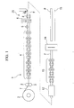
- Fig. 1 is a schematic structural diagram showing a production line for an electro-resistance-welded tube manufacturing apparatus
- Fig. 2 is a schematic plan view showing a pair of squeeze rolls and an electro-resistance-welded tube in a welding section of the manufacturing apparatus shown in Fig. 1
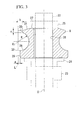
- Fig. 3 is a central vertical cross sectional view of a squeeze roll
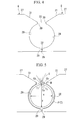
- Fig. 4 is a partial central vertical cross sectional view in which a pair of squeeze rolls are placed in an adjustment state in order to weld a strip
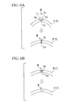
- Fig. 5 is a partial central vertical cross sectional view showing a pair of squeeze rolls during the welding of an electro-resistance-welded tube.
- the electro-resistance-welded tube according to the present embodiment is a simple metal tube having a smooth internal surface and is used as a hot water supply tube, a cold water supply tube, or the like, however, the present invention may also be applied to any metal tube such as a metal tube that has irregular structures formed on the external surface of the tube or that has grooves formed on the internal surface of the tube and is used in refrigerators or air-conditioning equipment.
- the material from which the electro-resistance-welded tube according to the present embodiment is formed is brass, however, the present invention may also be applied to copper tubes, aluminum tubes, or metal tubes formed from some other material.
- a strip T in the form of a continuous belt having a constant width that is formed from a belt of metal such as brass is continuously fed out from an uncoiler 2.
- the fed out strip T passes through a pair of pressing rolls 3 and then through a plurality of pairs of forming rolls 4 arranged in a row.
- the strip T is thus gradually rounded into the shape of a C.
- the induction heating coil 6 heats the strip T that has been rounded into a C shape and generates joule heat concentrated in both edges.
- the strip T passes through a pair of squeeze rolls 8 and 8, as is shown in Fig. 2, the two heated edges T1 and T2 are pressed and butt welded together to form a weld portion M.
- internal and external surface beads are formed from fused material extruded from the welded portion. These are removed by cutting apparatuses.
- the tube P After the tube P has passed through a cooling tank 12 and been forcibly cooled, it is shrunk to a predetermined external diameter by being passed through a plurality of pairs of sizing rolls 13 arranged in a row. After the tube P has been shaped by a shaping roll (not shown) it is cut into predetermined lengths, for example, 4 to 6 meters by a cutting apparatus 14 and the cut tubes are then stacked on a stock table 15.
- a pair of squeeze rolls 8 and 8 are provided sandwiching the strip T and aligned in a direction substantially orthogonal to the direction in which the strip T is transported.
- Each squeeze roll 8 has the vertical cross sectional configuration shown in Fig. 3.
- Each squeeze roll 8 is fixed in place by a rotation shaft 22 provided in the rotation center of the squeezer roll.
- the rotation shaft 22 is rotatably supported via bearings by a holding mechanism (not shown).
- the squeeze roll 8 and the rotation shaft 22 can be made to rotate integrally by, for example, fitting a key together with a key groove.
- Each squeeze roll 8 is formed substantially in a disk shape and has a center hole 26 into which the rotation shaft 22 is fitted penetrating the central portion of the squeeze roll 8 in the vertical direction.
- a concave curved surface 28 having a substantially arc shaped configuration whose vertical cross section has the radius R is formed around the entire periphery centering on the rotation shaft 22.
- the surface of the concave curved surface 28 may be, for example, a mirror finished surface and a lubricant such as a water soluble oil may be coated on this surface. This allows the C shaped strip T to be curled more easily into a tube shape.
- a lower side flange portion 29 whose outer surface is formed substantially in a circular cylinder configuration is formed below the bottom end of the concave curved surface 28.
- An upper side flange portion 30 whose outer surface is formed substantially in a circular cylinder configuration having a predetermined thickness c is formed above the top end of the concave curved surface 28.
- the thickness c may be set within the range of 1 to 2 mm, for example, which ensures sufficient mechanical strength. If c is less than 1 mm, the mechanical strength of this portion is too small making it probable that a failure will occur.
- c is greater than 2 mm, the concern exists that spatter that is scattered from the weld portion M in the electro-resistance-welded tube P will hit the upper side flange portion 30 and fall onto the top of the electro-resistance-welded tube P and then become adhered thereto and harden.
- a substantially truncated cone shaped tapered surface 31 is formed sloping upwards from the top end of the upper side flange portion 30 towards a top surface 27 in which the center hole 26 is formed.
- the angle of inclination of the tapered surface 31 may be set to an appropriate acute angle.
- the bottom end of the concave curved surface 28, which is the portion where the concave curved surface 28 intersects with the lower side flange portion 29 is a curved portion 32 that is curved in an arc shape having the radius R.
- a virtual line L is provided substantially parallel to the center axis O of the rotation shaft 22 opposite the concave curved surface 28 of each squeeze roll 8, and a center point O 1 of the radius R of the concave curved surface 22 is taken as being on the virtual line L. If the distance from the virtual line L to the lower side flange portion 29 is taken as a, and the distance from the virtual line L to the upper side flange portion 30 is taken as b, then the relationship a ⁇ b exists. Namely, the distance from the upper side flange portion 30 to the rotation shaft 22 is set shorter than the distance from the lower side flange portion 29 to the rotation shaft 22.
- FIG. 4 A state in which a pair of squeeze rolls 8 and 8 having the above described structure are mounted on a production line for an electro-resistance-welded tube P is shown in Fig. 4.
- the squeeze rolls 8 and 8 shown in Fig. 4 are in a state of adjustment prior to the transporting of the strip T and the lower side flange portions 29 and 29 of each squeeze roll 8 are butted together in the drawing.
- a small gap 33 is provided between the upper side flange portions 30 and 30 that includes the area between the upper ends of the concave curved surfaces 28 and 28.
- the gap between the pair of squeeze rolls 8 and 8 can be adjusted as is appropriate by an adjustment means (not shown) and may be adjusted in accordance with the outer diameter and thickness of the electro-resistance-welded tube P.
- the gap between the pair of squeeze rolls 8 and 8 is set appropriately in accordance with the outer diameter and thickness of the electro-resistance-welded tube P, the gap is set such that the weld portion M in the electro-resistance-welded tube P always protrudes from the concave curved surface 28 into the gap 33 during welding.
- the squeeze rolls 8 have the above described structure and prior to the manufacturing of the electro-resistance-welded tube P the positions of the squeeze rolls 8 and 8 are adjusted in the squeeze roll unit 20. Firstly, before the strip T is transported, as is shown in Fig. 4, the lower side flange portions 29 and 29 of the pair of squeeze rolls 8 and 8 are butted together and, in this state, the thickness of the spacers 24 are adjusted such that the heights of each concave curved surface 28 and 28 are the same. The abutting portions of the lower side flange portions 29 and 29 are also adjusted such that they are positioned at a join position that is also the center of the strip T.
- the squeeze rolls 8 and 8 are opened wide, the strip T is passed between the concave curved surfaces 28 and 28 and the distance between the squeeze rolls 8 and 8 is appropriately set.
- the distance may be set such that the lower side flange portions 29 and 29 are a slight distance apart and the centerline of the radius R is at an identical position between the two concave curved surfaces 28 and 28. In this state, the distance between the upper side flange portions 30 and 30 is 2b.
- the manufacturing of the electro-resistance-welded tube P is performed.
- a strip T formed from brass, for example is continuously fed out from an uncoiler 2.
- the fed out strip T passes through forming rolls 4 and is gradually curled into the shape of a C.
- the strip T is then passed through the induction heating coil 6 of an induction heating section.
- the strip T that has been heated by the induction heating coil 6 passes through the pair of squeeze rolls 8 and 8, the two heated edges T1 and T2 are pressed and butt welded together.
- the areas adjacent to the two edges T1 and T2 located inside the gap 33 away from the concave curved surfaces 28 have a larger radius of curvature than the portions located inside the concave curved surfaces 28 and protrude substantially with a mountain peak shaped cross section.
- the strip T has a substantially egg shape or teardrop shape and, as is seen in Fig. 6A, when the top edges tb and tb in the thickness direction of the two edges T1 and T2 of the weld portion M are opened up away from each other, the bottom edges ta and ta can be fused and welded together. The two edges T1 and T2 are then gradually pushed together so that the top edges tb and tb are welded. In particular, because the two edges T1 and T2 that are heated by the work coil 6 are heated from the top side thereof, the top edge tb has the higher heating temperature and fuses more easily.
- the two edges T1 and T2 are reliably heated across their entire thickness direction as the heating fusion progresses so that there is no fear of the two edges T1 and T2 separating.
- the electro-resistance-welded tube P that is formed in this case is formed with a slightly larger radius of curvature in the gap 33 between the upper side flange portions 30 and 30 than in the portions positioned inside the concave curved surface 28 so that there is no sinking towards the interior. Therefore, the electro-resistance-welded tube P has a substantially egg shape, as seen in a vertical cross sectional view, with the maximum length y in the vertical direction (i.e., the vertical axis) including the weld portion M being longer than the maximum length x in the horizontal direction (i.e., the horizontal axis). As a result, the subsequent shaping processing is simplified.
- spatter is generated in the weld portion M.
- more spatter is scattered when the strip T is made from brass than when another material is used.
- the spatter s is scattered with the weld portion M of the two edges T1 and T2 protruding into the gap 33 between the upper side flange portions 30 and 30.
- the majority of the spatter s is scattered to the outside.
- the spatter Because the spatter s scatters peripherally along the tapered surfaces 31 and 31 of the squeeze rolls 8 and 8, and because the thickness c of the upper side flange portion 30 is limited to a range of 1 to 2 mm, the spatter hits the upper side flange portions 30 and 30, bounces back, and can thus be largely prevented from adhering to the electro-resistance-welded tube P.
- the gap between the lower side flange portions 29 and 29 is smaller than the gap 33, prevention of the bottom portion of the tube P from sinking and deforming is ensured.
- the two edges T1 and T2 of the strip T are thus reliably welded and a high quality electro-resistance-welded tube P can be manufactured.
- the gap between the lower side flange portions 29 and 29 is smaller than the gap 33 between the upper side flange portions 30 and 30, the bottom portion of the electro-resistance-welded tube P can be prevented during welding from sinking into the gap between the lower side flange portions 29 and 29 and becoming deformed.
- the manufacturing apparatus for an electro-resistance-welded tube because the distance from the rotation shaft of a squeeze roll to the top edge of a concave curved surface is less than the distance to the bottom edge of the concave curved surface, the area of the strip adjacent to the two edges thereof protrude outwards from the gap between the top edges of the two concave curved surfaces. Therefore, the two edges are gradually welded starting from the bottom edge side in the thickness direction thereof and moving to the top edge side. This enables the two edges to be reliably heat fused and welded from the bottom edge thereof moving towards the top edge thereof, and enables a high quality electro-resistance-welded tube to be manufactured having a high weld strength with no sinking of the weld portion. In addition, spatter that is generated in the weld portion can be reliably made to scatter towards the outside.
- the welded electro-resistance-welded tube is formed substantially in an egg shape or teardrop shape with the weld portion of the two edges protruding from the gap. Consequently, the heat fusing is performed starting from the bottom end in the thickness direction of the two edges and moving to the top end thereof and the weld strength is high with no sinking occurring.
- a tapered surface that slopes towards the rotation shaft of each squeeze roll via the upper side flange portion having a predetermined thickness is formed at the top edge side of the concave curved surface of each squeeze roll, failure is largely prevented at the upper side flange portion and the strength of the squeeze roll is increased.
- the tapered surface at the top of the squeeze roll when spatter scatters from the weld portion the spatter is distributed along the tapered surface and can be kept away from the surface of the electro-resistance-welded tube. As a result, spatter can be prevented from adhering to the surface of the electro-resistance-welded tube.
- the two edges of a strip that are passing through squeeze rolls are welded starting from the top edge in the thickness direction of the strip, the two edges are gradually heat fused and welded starting from the bottom edge side moving to the top edge side.
- This enables a high quality electro-resistance-welded tube to be manufactured having a high weld strength with no sinking of the weld portion.
- spatter that is generated in the weld portion can be reliably made to scatter towards the outside.
- the two edges of a strip are welded with the portion of the strip adjacent to the two edges protruding outwards as seen in a vertical cross sectional view, and the vertical axis is longer than the horizontal axis as seen in a vertical cross sectional view, during welding the two edges are welded from the bottom edge thereof moving towards the top edge, enabling a high quality electro-resistance-welded tube to be manufactured with no deficiency in the weld strength and with no sinking of the weld portion.
Landscapes
- Engineering & Computer Science (AREA)
- Mechanical Engineering (AREA)
- Butt Welding And Welding Of Specific Article (AREA)
- Bending Of Plates, Rods, And Pipes (AREA)
Applications Claiming Priority (2)
| Application Number | Priority Date | Filing Date | Title |
|---|---|---|---|
| JP2001178932 | 2001-06-13 | ||
| JP2001178932A JP2003001324A (ja) | 2001-06-13 | 2001-06-13 | 電縫管の製造装置及び製造方法 |
Publications (2)
| Publication Number | Publication Date |
|---|---|
| EP1270100A2 true EP1270100A2 (de) | 2003-01-02 |
| EP1270100A3 EP1270100A3 (de) | 2004-06-09 |
Family
ID=19019557
Family Applications (1)
| Application Number | Title | Priority Date | Filing Date |
|---|---|---|---|
| EP02291446A Withdrawn EP1270100A3 (de) | 2001-06-13 | 2002-06-11 | Vorrichtung und Verfahren zur Herstellung eines elektro-widerstandgeschweissten Rohres |
Country Status (5)
| Country | Link |
|---|---|
| US (1) | US20020190094A1 (de) |
| EP (1) | EP1270100A3 (de) |
| JP (1) | JP2003001324A (de) |
| KR (1) | KR20020095091A (de) |
| CN (1) | CN1390674A (de) |
Families Citing this family (3)
| Publication number | Priority date | Publication date | Assignee | Title |
|---|---|---|---|---|
| CN111421265B (zh) * | 2020-03-25 | 2021-04-09 | 武汉理工大学 | 一种罐体用焊前预热及焊后热处理装置 |
| EP4164818B1 (de) * | 2020-06-15 | 2025-10-22 | Hydro Extruded Solutions AS | Nahtführungsanordnung, vorrichtung zum walzenformen von schweissbaren rohren mit einer solchen nahtführungsanordnung und verfahren zur herstellung eines rohrs aus aluminium oder seinen legierungen |
| CN119016933B (zh) * | 2024-10-30 | 2025-02-11 | 常州时进精密机械有限公司 | 自动化钢管加工生产线及工作方法 |
Family Cites Families (6)
| Publication number | Priority date | Publication date | Assignee | Title |
|---|---|---|---|---|
| JPS55144325A (en) * | 1979-04-27 | 1980-11-11 | Nippon Steel Corp | Preventing method of counterflow of cooling water in pipe when producing electric welded pipe |
| JPH08103815A (ja) * | 1994-09-30 | 1996-04-23 | Ngk Spark Plug Co Ltd | セラミック製スクイズロール |
| JPH09277068A (ja) * | 1996-04-11 | 1997-10-28 | Hitachi Cable Ltd | 電縫管の製造方法 |
| JP3259647B2 (ja) * | 1996-12-12 | 2002-02-25 | 日本鋼管株式会社 | 溶接管の製造方法 |
| JP3166643B2 (ja) * | 1996-12-24 | 2001-05-14 | 住友金属工業株式会社 | レーザ溶接管製造装置およびレーザ溶接管の製造方法 |
| JP3360620B2 (ja) * | 1998-09-03 | 2002-12-24 | 日本鋼管株式会社 | 高エネルギービームによる溶接鋼管の製造方法 |
-
2001
- 2001-06-13 JP JP2001178932A patent/JP2003001324A/ja not_active Withdrawn
-
2002
- 2002-06-03 KR KR1020020031015A patent/KR20020095091A/ko not_active Withdrawn
- 2002-06-11 EP EP02291446A patent/EP1270100A3/de not_active Withdrawn
- 2002-06-11 CN CN02123049.8A patent/CN1390674A/zh active Pending
- 2002-06-11 US US10/167,126 patent/US20020190094A1/en not_active Abandoned
Also Published As
| Publication number | Publication date |
|---|---|
| CN1390674A (zh) | 2003-01-15 |
| EP1270100A3 (de) | 2004-06-09 |
| US20020190094A1 (en) | 2002-12-19 |
| KR20020095091A (ko) | 2002-12-20 |
| JP2003001324A (ja) | 2003-01-07 |
Similar Documents
| Publication | Publication Date | Title |
|---|---|---|
| EP0696718B1 (de) | Rohr für einen Wärmeaustauscher | |
| EP1260284A2 (de) | Vorrichtung zur Herstellung von geschweissten Rohren und Vorrichtung zum Schneiden des Schweisswulstes auf der Innenseite der geschweissten Rohre | |
| US5163602A (en) | Multi-walled steel pipe, a method of making the same and a metal strip for use in making the same | |
| JP2001259733A (ja) | 電縫管の製造装置および製造方法 | |
| EP0511746B1 (de) | Verfahren zur Herstellung von Artikeln mittels Laserstrahlschweissen | |
| EP1270100A2 (de) | Vorrichtung und Verfahren zur Herstellung eines elektro-widerstandgeschweissten Rohres | |
| JP2948515B2 (ja) | 内面溝付伝熱管およびその製造方法 | |
| JP7692440B2 (ja) | ロール成形及び溶接されたチューブの製造のための金属ストリップを予備成形するための装置及び方法 | |
| EP0591693B1 (de) | System zum Nuten und Walzen von länglichen Körpern und daraus entstehende flache Rohre für Wärmeaustauscher | |
| JP2000346580A (ja) | 内面溝付伝熱管、その製造方法および製造装置 | |
| JP3069277B2 (ja) | 内面溝付伝熱管およびその製造方法 | |
| JP2023530920A (ja) | エンボス加工ロール | |
| EP1219377A1 (de) | Herstellungsvorrichtung zum erwärmen von rohren mit inneren nuten und rohrwalze | |
| JPH04339584A (ja) | 金属筒体の製造方法 | |
| JP2002263770A (ja) | 溝付伝熱管の製造装置およびフィン転造ロール | |
| JP2930249B2 (ja) | 内面溝付き管の製造方法 | |
| TWI892252B (zh) | 電阻焊鋼管的製造方法及電阻焊鋼管 | |
| JP3122368B2 (ja) | 金属管の電縫装置 | |
| JP3283166B2 (ja) | 内面溝付伝熱管製造用素材および内面溝付伝熱管の製造方法 | |
| JP2002126846A (ja) | 転造加工用ロールおよび内面溝付伝熱管の製造装置 | |
| JPH0248350B2 (de) | ||
| JP3599515B2 (ja) | 溶接管用溝付条およびその製造方法 | |
| JPH09155443A (ja) | 内面溝付伝熱管の製造方法および製造装置 | |
| JP2863722B2 (ja) | 内面溝付伝熱管およびその製造方法 | |
| JP2732935B2 (ja) | 粉粒体充填管の製造方法 |
Legal Events
| Date | Code | Title | Description |
|---|---|---|---|
| PUAI | Public reference made under article 153(3) epc to a published international application that has entered the european phase |
Free format text: ORIGINAL CODE: 0009012 |
|
| AK | Designated contracting states |
Kind code of ref document: A2 Designated state(s): AT BE CH CY DE DK ES FI FR GB GR IE IT LI LU MC NL PT SE TR |
|
| AX | Request for extension of the european patent |
Free format text: AL;LT;LV;MK;RO;SI |
|
| PUAL | Search report despatched |
Free format text: ORIGINAL CODE: 0009013 |
|
| AK | Designated contracting states |
Kind code of ref document: A3 Designated state(s): AT BE CH CY DE DK ES FI FR GB GR IE IT LI LU MC NL PT SE TR |
|
| AX | Request for extension of the european patent |
Extension state: AL LT LV MK RO SI |
|
| AKX | Designation fees paid | ||
| REG | Reference to a national code |
Ref country code: DE Ref legal event code: 8566 |
|
| STAA | Information on the status of an ep patent application or granted ep patent |
Free format text: STATUS: THE APPLICATION IS DEEMED TO BE WITHDRAWN |
|
| 18D | Application deemed to be withdrawn |
Effective date: 20041210 |