EP1266793A2 - Fahrzeugsitz - Google Patents
Fahrzeugsitz Download PDFInfo
- Publication number
- EP1266793A2 EP1266793A2 EP02012532A EP02012532A EP1266793A2 EP 1266793 A2 EP1266793 A2 EP 1266793A2 EP 02012532 A EP02012532 A EP 02012532A EP 02012532 A EP02012532 A EP 02012532A EP 1266793 A2 EP1266793 A2 EP 1266793A2
- Authority
- EP
- European Patent Office
- Prior art keywords
- vehicle seat
- seat
- weight adjustment
- flexible element
- seat plate
- Prior art date
- Legal status (The legal status is an assumption and is not a legal conclusion. Google has not performed a legal analysis and makes no representation as to the accuracy of the status listed.)
- Granted
Links
- 239000000725 suspension Substances 0.000 description 8
- 238000005086 pumping Methods 0.000 description 4
- 238000010586 diagram Methods 0.000 description 2
- 238000012790 confirmation Methods 0.000 description 1
- 238000010276 construction Methods 0.000 description 1
- 230000012447 hatching Effects 0.000 description 1
- 239000003550 marker Substances 0.000 description 1
- 238000000034 method Methods 0.000 description 1
- 230000010355 oscillation Effects 0.000 description 1
- 230000004584 weight gain Effects 0.000 description 1
- 235000019786 weight gain Nutrition 0.000 description 1
- 230000004580 weight loss Effects 0.000 description 1
Images


Classifications
-
- B—PERFORMING OPERATIONS; TRANSPORTING
- B60—VEHICLES IN GENERAL
- B60N—SEATS SPECIALLY ADAPTED FOR VEHICLES; VEHICLE PASSENGER ACCOMMODATION NOT OTHERWISE PROVIDED FOR
- B60N2/00—Seats specially adapted for vehicles; Arrangement or mounting of seats in vehicles
- B60N2/50—Seat suspension devices
- B60N2/502—Seat suspension devices attached to the base of the seat
-
- B—PERFORMING OPERATIONS; TRANSPORTING
- B60—VEHICLES IN GENERAL
- B60N—SEATS SPECIALLY ADAPTED FOR VEHICLES; VEHICLE PASSENGER ACCOMMODATION NOT OTHERWISE PROVIDED FOR
- B60N2/00—Seats specially adapted for vehicles; Arrangement or mounting of seats in vehicles
- B60N2/50—Seat suspension devices
- B60N2/505—Adjustable suspension including height adjustment
-
- B—PERFORMING OPERATIONS; TRANSPORTING
- B60—VEHICLES IN GENERAL
- B60N—SEATS SPECIALLY ADAPTED FOR VEHICLES; VEHICLE PASSENGER ACCOMMODATION NOT OTHERWISE PROVIDED FOR
- B60N2/00—Seats specially adapted for vehicles; Arrangement or mounting of seats in vehicles
- B60N2/50—Seat suspension devices
- B60N2/506—Seat guided by rods
- B60N2/508—Scissors-like structure
-
- B—PERFORMING OPERATIONS; TRANSPORTING
- B60—VEHICLES IN GENERAL
- B60N—SEATS SPECIALLY ADAPTED FOR VEHICLES; VEHICLE PASSENGER ACCOMMODATION NOT OTHERWISE PROVIDED FOR
- B60N2/00—Seats specially adapted for vehicles; Arrangement or mounting of seats in vehicles
- B60N2/50—Seat suspension devices
- B60N2/54—Seat suspension devices using mechanical springs
- B60N2/544—Compression or tension springs
Definitions
- the invention relates to a vehicle seat with an arranged on a base Seat plate and with a spring device provided for weight adjustment, which is connected to a weight setting confirmation device.
- Such vehicle seats come for example in trucks, tractors, Construction machinery etc. used. These vehicle seats are for example between 50 and 130 kg weight of the respective seat user with the help of the Weight adjustment actuator adjustable.
- the Weight adjustment of the vehicle seat only the estimated weight of the of the respective seat user. Has the weight of the Seat user due to weight gain or loss or due to the clothing of the Seat user changed, however, so far there is no optimal Weight adjustment of the vehicle seat.
- the suspension of the Vehicle seat i.e. the seat plate, not optimally adjusted in relation to the base is.
- the suspension of the vehicle seat is therefore not optimal Vibration range of the vehicle seat.
- Either the suspension is the Vehicle seat by means of the weight adjustment Spring device set too hard, so that the swing or spring travel over the optimal swing or spring travel and the swing amplitude is small, or the spring device provided for weight adjustment becomes too soft set so that the swing or spring travel below the optimal Vibration or spring travel of the vehicle seat is.
- the invention has for its object a vehicle seat of the beginning to create mentioned type, in which a simple operation to adjust the Vehicle seat on the respective weight of a seat user very safe and is reliably possible in order to ensure optimal suspension of the vehicle seat cause.
- This task is carried out in a vehicle seat of the type mentioned solved according to the invention in that the weight adjustment actuator a level indicator is assigned to the Display of the setting of the seat plate to the weight of the seat user in with respect to the travel of the seat plate optimally corresponding seat plate levels is provided, wherein the level indicator and the weight adjustment actuator are provided centrally on the front edge of the seat plate.
- the level display device With the help of the level display device, it is easy and reliable to do that the spring device provided for weight adjustment fits exactly like this adjust that an exact adjustment of the suspension of the vehicle seat on the actual weight of the respective seat user is possible.
- the Weight adjustment actuating device targeted by the respective seat user operated in such a way until the level display device with respect to the Travel of the seat plate shows the optimal seat plate level. In this case leads the seat plate of the vehicle seat in the operation of the vehicle has a suspension in optimal travel range.
- the level indicator and the weight adjustment actuator are provided centrally on the front edge of the seat plate, results the advantage that the respective seat user during weight adjustment sits straight and thus loads the seat plate evenly, the Weight adjustment actuator by its on the front edge of the seat plate central arrangement is easily accessible and can be operated optimally.
- the level indicator means between by means of a spring element the base and the seat plate are mechanically pre-tensioned flexible element and one associated with the elongated flexible element Indicator body.
- the elongated flexible element can be a pointer and the The indicator body can have a viewing opening into which the pointer protrudes.
- the elongated flexible element can be a wire, a rope, a Cord or the like be educated.
- the pointer is fixed to the elongated flexible element.
- the viewing opening of the display body, into which the pointer stands, is on hers Edge expediently provided with a marking, as it were Scaling forms. This marking can differ from color areas Color, of symbols in combination with color markings or the like.
- the optimal seat level range can be green or yellow be marked. Right and connect a red box on the left to give a simple indication that the vehicle seat is not optimally adjusted when the pointer is in one of the two red areas.
- the outside of the optimal Areas located on the seat plate level can also be, for example illustrated by the symbol of a small man or a tall man his.
- the display body can therefore be a marker for the each seat user optimally corresponding with respect to the spring travel Have seat level.
- the elongated flexible Element a marking for the respective seat user in relation to the Travel optimally appropriate seat level and that the indicator body a has relatively small viewing opening for the elongated flexible element. While at the above-mentioned training of the level display device with a The viewing aperture of the indicator body is sufficient Length extension is in the latter training, in which the elongated flexible element a mark for the particular seat user in has optimally corresponding seat level in relation to the spring travel, which Sight opening dimensioned relatively short in order to provide a correspondingly accurate display realize.
- this is elongated, flexible Element preferably formed by a band, the display body a Has viewing opening for the tape.
- a tape is easy with corresponding markings in the form of colored areas or in Shape of pictograms, geometric figures or the like. designed.
- Vehicle seat of the indicator body is provided in the center of the front edge of the seat plate is.
- a vehicle seat designed in this way has the advantage that the Seat user sits straight on the vehicle seat during weight adjustment and looks down to the front of the display body, so that on the vehicle seat actually the respective weight of the seat user evenly, symmetrically is effective.
- the weight adjustment actuator may have a handle that between a surrounding or closely enclosing the display body Inactive position and an active position spaced from the display body back and forth is adjustable. In the inactive position, the handle of the Weight adjustment actuator on the vehicle seat not disturbing noticeable.
- the Handle In the active position spaced from the display body, the Handle, for example, around a horizontal swivel axis around a defined one Pumping angle can be swiveled up and down in order to achieve the Adjust the spring mechanism of the vehicle seat step by step. The can both towards a lightweight seat user and in Direction of a heavy seat user, i.e. for example in one Weight range between 50 and 130 kg happen.
- the handle between the Inactive position and the active position linear, i.e. back and forth in the longitudinal direction of the seat adjustable and in the active position for gradual pumping adjustment of the spring device provided for weight adjustment around a horizontal Swivel axis can be swiveled up and down.
- Another option is there according to the invention in that the handle about a vertical axis between the Inactive position and the active position back and forth adjustable and in the Active position for the gradual pumping adjustment of the Weight adjustment provided spring device around a horizontal Swivel axis can be swiveled up and down.
- FIG 1 shows schematically in a side view an embodiment of the Vehicle seat 10 having a seat plate 12 and a backrest 14.
- the Vehicle seat 10 also has a base 16. Between the base 16 and a scissor-type frame 18 is provided on the seat plate 12.
- the scissor frame 18 has a pair of side first scissor members 20 and a pair of side second Scissor elements 22.
- the first and second scissor elements 20 and 22 are pivotable with one another by means of a connecting axis 24 connected.
- the first scissor elements 20 are at one end 26 on the Seat plate 12 is pivotally attached.
- the second scissor elements 22 are with its first end 28 pivotally attached to the base 16.
- the second ends 30 of the first scissor elements 20 are along linear guides 32 guided linearly, which are provided on the base 16.
- the second Ends 34 of the second scissor elements 22 are linear along linear guides 36 movably guided, which are provided on the seat plate 12.
- a surface element 38 is located between the two first scissor elements 20 fixed, which is oriented parallel to the seat plate 12. Between the seat plate 12 and the surface element 38, a spring device 40 is arranged, which for Weight adjustment of the vehicle seat 10 back and forth in the longitudinal direction of the seat is adjustable. This is indicated by the double arrow 42.
- the spring device 40 is adjusted toward the first end 26. Takes on the Vehicle seat 10 a heavy seat user space, this adjusts the Spring device 40 away from first end 26 to be on vehicle seat 10 Adjust weight appropriately.
- the spring device 40 is adjusted with a Weight adjustment actuator 44 connected below in Connection with Figure 6 is described in more detail.
- the vehicle seat 10 to display the setting of the seat plate the weight of the respective seat user in relation to the travel of the Seat plate 12 optimally corresponding seat plate level a level indicator 46 on.
- Two configurations of the level display device 46 are shown schematically in Figures 4 and 5; FIG. 6 illustrates a corresponding to the principle of the training according to FIG. 4 - level display device 46 in conjunction with the aforementioned preferred Weight adjustment actuator 44.
- FIG. 2 illustrates the diagram with a double arrow 48 indicated overall vibration path of the seat plate 12 with respect to the base 16 of the vehicle seat 10 (see FIG. 1).
- This optimal setting range 50 is by a double arrow or by hatching clarified.
- FIG 4 shows schematically sections of the seat plate 12 and the base 16 of the Vehicle seat 10 and a training of the level indicator 46.
- Die Level indicator 46 has an elongated flexible member 52 that is connected to a spring element 54.
- the elongated flexible member 52 is formed by a wire 56, which has one end 58 fixed to the base 16 is.
- the second end 60 of the wire 56 is connected to the spring element 54.
- the spring element 54 is at its end 62 remote from the end 60 Seat plate 12 fixed.
- the elongated flexible element 52, i.e. the wire 56 and that Spring element 54 are dimensioned such that the spring element 54 in assembled state of the level indicator 46 mechanically is excited.
- the wire 56 is provided around the seat plate 12 Deflected element 64 deflected.
- a pointer 66 is fixed to the wire 56 and extends into a viewing opening 68 Indicator body 70 stands inside.
- the display body 70 so to speak, one Forms scale body, is at the edge 72 of the viewing opening 68 with a marking 74 Mistake.
- the marking 74 has, for example, a green or yellow color Middle area 76.
- This central region 76 is adjoined on the right and left each an outer area 78, which e.g. is colored red.
- the central area 76 corresponds to the optimal setting range 50 (see FIG. 2).
- the pointer is 66 in the central area 76, then the seat user has the vehicle seat 10 on the seat plate level optimally adjusted to its weight. This Adjustment takes place with the aid of the weight adjustment actuating device 44, as it is is schematically illustrated in Figure 1.
- FIG. 5 shows a perspective illustration similar to FIG. 4 sections of the base 16 and the seat plate 12 of the vehicle seat 10 and another embodiment of the level indicator 46.
- the level indicator 46 has an elongated flexible member 52 extending from a band 80 is formed.
- the band 80 is at one end 82 on the Base 16 fixed.
- the second end 83 of the band 80 is with a spring element 54 connected.
- the spring element 54 has its second end 83 distal end 62 attached to the seat plate 12.
- the band 80 and that Spring element 54 are dimensioned such that the spring element 54 in assembled state of the level indicator 46 mechanically is excited.
- the elongated flexible element 52 designed as a band 80 extends through a display body 84 therethrough, which with one compared to the training 4 short viewing opening 86 is formed.
- the level indicator 46 is not the indicator body 84 at the edge of the Viewing opening 86 but provide the band 80 with a marking 88.
- This Mark 88 again has a green, yellow or other colored or with a suitable symbol provided on the middle region 90, on the right and an outer area 92 connects to the left. Is in the viewing opening 86 of the display body 84, the central region 90 of the marking 88, then the Vehicle seat 10 to the actual weight of the vehicle seat 10 seated seat user optimally adjusted with regard to the vibration behavior.
- One of the two outer regions 92 is located in the viewing opening 86 Mark 88, then the seat user must use the weight adjustment actuator 54 (see Figure 1) to activate the To adjust spring device 40 so that a suitable weight setting and optimal suspension is achieved.
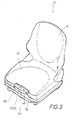
- FIG. 3 shows a perspective view of an embodiment of the Vehicle seat 10 with its seat plate 12 and the backrest 14.
- FIG. 3 also clarifies that the display body 70 (see FIG. 4) and the Indicator body 84 (see FIG. 5) of the level indicator 46 at the front edge 94 of the seat plate 12 is provided in the center.
- the display body 70 or 84 of the Level indicator 46 is the weight adjustment actuator 44 assigned.
- the weight adjustment actuator 44 has one bow-shaped handle 96, the one drawn in Figure 3 Inactive position and one spaced from the display body 70 or 84 Active position is adjustable. This is illustrated in Figure 6.
- FIG. 6 shows a perspective view of a preferred embodiment of the Weight adjustment actuator 44 and an embodiment of the level indicator 46, similar to that schematically illustrated in FIG. 4 Education.
- the level display device 46 has a display body 70 an elongated viewing opening 68.
- a pointer 66 stands in the viewing opening 68 into it, which is fixed to a wire 56.
- the wire 56 is around two deflection elements 64 deflected, which protrude from a mounting body 98.
- the wire 56 is with one end at the base 16 of the vehicle seat 10 (see, for example Figure 4) fixed.
- the second end of the wire 56 is provided with a spring element 54 connected, which is fixed to the underside of the mounting body 98.
- the Mounting body 68 is attached to the seat plate 12.
- the mounting body 98 is formed with bearing recesses 100.
- the Bearing recesses 100 are used for the pivotable mounting of a bearing axis 102. Are spaced apart from one another and from one another by the bearing axis 102 parallel oriented sleeve elements 104 away. Through the two sleeve elements 104 Leg members 106 extend movably therethrough, towards each other a U-shaped bracket 108 are connected. On the U-shaped bracket 108 is the Handle 96 of the weight adjustment actuator 44 attached.
- the spring device 40 is connected to the adjusting element 122 (see FIG. 1), so that it is possible by an oscillating pivoting of the handle 96, the spring device 44 towards the first end 26 or away from it adjust to the vehicle seat 10 optimally to the weight of each Adjust seat user, the optimal weight or Suspension setting is reached when the pointer 66 of the level indicator 46 in the optimal setting range 50 (see, for example Figure 2), i.e. located in the central region 76 of the marking 74.
Landscapes
- Engineering & Computer Science (AREA)
- Aviation & Aerospace Engineering (AREA)
- Transportation (AREA)
- Mechanical Engineering (AREA)
- Seats For Vehicles (AREA)
Abstract
Description
- Figur 1
- in einer Seitenansicht schematisch eine Ausbildung des Fahrzeugsitzes,
- Figur 2
- eine Diagrammdarstellung des Schwingweges der Sitzplatte in bezug
auf die Basis des Fahrzeugsitzes gemäß Figur 1 sowie des in der
Mitte
dieses gesamten Schwingweges befindlichen optimalen Einstellbereiches der Federeinrichtung des Fahrzeugsitzes gemäß Figur 1, - Figur 3
- eine perspektivische Darstellung eines Fahrzeugsitzes, wie er in
Figur 1
schematisch, stark abstrahiert, dargestellt ist, - Figur 4
- abgeschnitten eine perspektivische schematische Ansicht einer
Ausbildung
der Niveau-Anzeigeeinrichtung des Fahrzeugsitzes gemäß Figur 1 bzw. 3, - Figur 5
- eine der Figur 4 ähnliche abgeschnittene räumliche Darstellung einer
anderen Ausbildung der Niveau-Anzeigeeinrichtung des
Fahrzeugsitzes
gemäß den Figuren 1 oder 3, und - Figur 6
- eine perspektivische Darstellung einer bevorzugten Ausbildung der Gewichtseinstell-Betätigungseinrichtung des Fahrzeugsitzes gemäß den Figuren 1 oder 3 mit der Niveau-Anzeigeeinrichtung, wie sie in Figur 4 schematisch verdeutlicht ist.
Claims (11)
- Fahrzeugsitz mit einer auf einer Basis (16) angeordneten Sitzplatte (12) und mit einer zur Gewichtseinstellung vorgesehenen Federeinrichtung (40), die mit einer Gewichtseinstell-Betätigungseinrichtung (44) verbunden ist,
dadurch gekennzeichnet, daß der Gewichtseinstell-Betätigungseinrichtung (44) eine Niveau-Anzeigeeinrichtung (46) zugeordnet ist, die zur Anzeige der Einstellung der Sitzplatte (12) auf das dem Gewicht des jeweiligen Sitzbenutzers in bezug auf den Federweg (48) der Sitzplatte (12) optimal entsprechenden Sitzplattenniveaus vorgesehen ist, wobei die Niveau-Anzeigeeinrichtung (46) und die Gewichtseinstell-Betätigungseinrichtung (44) am Vorderrand (94) der Sitzplatte (12) mittig vorgesehen sind. - Fahrzeugsitz nach Anspruch 1,
dadurch gekennzeichnet, daß die Niveau-Anzeigeeinrichtung (46) ein mittels eines Federelementes (54) zwischen der Basis (16) und der Sitzplatte (12) mechanisch vorgespannt angeordnetes längliches flexibles Element (52) und einen dem länglichen flexiblen Element (52) zugeordneten Anzeigekörper (70; 84) aufweist. - Fahrzeugsitz nach Anspruch 2,
dadurch gekennzeichnet, daß das längliche flexible Element (52) einen Zeiger (66) und daß der Anzeigekörper (70) eine längliche Sichtöffnung (68) aufweist, in die der Zeiger (66) hineinsteht. - Fahrzeugsitz nach Anspruch 3,
dadurch gekennzeichnet, daß das längliche flexible Element (52) von einem Draht (56) gebildet ist. - Fahrzeugsitz nach Anspruch 3,
dadurch gekennzeichnet, daß der Anzeigekörper (70) eine Markierung (74) für das dem jeweiligen Sitzbenutzer in bezug auf den Federweg (48) optimal entsprechende Sitzniveau aufweist. - Fahrzeugsitz nach Anspruch 2,
dadurch gekennzeichnet, daß das längliche flexible Element (52) eine Markierung (88) für das dem jeweiligen Sitzbenutzer in bezug auf den Federweg (48) optimal entsprechende Sitzniveau und daß der Anzeigekörper (84) eine kleine Sichtöffnung (86) für das längliche flexible Element (52) aufweist. - Fahrzeugsitz nach Anspruch 6,
dadurch gekennzeichnet, daß das längliche flexible Element (52) von einem Band (80) gebildet ist. - Fahrzeugsitz nach einem der Ansprüche 2 bis 7,
dadurch gekennzeichnet, daß der Anzeigekörper (70; 84) am Vorderrand (94) der Sitzplatte (12) mittig vorgesehen ist. - Fahrzeugsitz nach einem der Ansprüche 2 bis 8,
dadurch gekennzeichnet, daß die Gewichtseinstell-Betätigungseinrichtung (44) einen Handgriff (96) aufweist, der zwischen einer zum Anzeigekörper (70; 84) benachbarten Inaktivstellung und einer vom Anzeigekörper (70; 84) beabstandeten Aktivstellung verstellbar ist. - Fahrzeugsitz nach Anspruch 9,
dadurch gekennzeichnet, daß der Handgriff (96) zwischen der Inaktivstellung und der Aktivstellung linear in Sitzlängsrichtung hin und her verstellbar und in der Aktivstellung zum schrittweisen Verstellen der zur Gewichtseinstellung vorgesehenen Federeinrichtung (40) um eine horizontale Schwenkachse auf und ab schwenkbar ist. - Fahrzeugsitz nach Anspruch 9,
dadurch gekennzeichnet, daß der Handgriff (96) um eine vertikale Achse zwischen der Inaktivstellung und der Aktivstellung hin und her verstellbar und in der Aktivstellung zum schrittweisen Verstellen der zur Gewichtseinstellung vorgesehenen Federeinrichtung (40) um eine horizontale Schwenkachse auf und ab schwenkbar ist.
Applications Claiming Priority (2)
| Application Number | Priority Date | Filing Date | Title |
|---|---|---|---|
| DE10129127 | 2001-06-16 | ||
| DE10129127A DE10129127B4 (de) | 2001-06-16 | 2001-06-16 | Fahrzeugsitz |
Publications (3)
| Publication Number | Publication Date |
|---|---|
| EP1266793A2 true EP1266793A2 (de) | 2002-12-18 |
| EP1266793A3 EP1266793A3 (de) | 2004-05-12 |
| EP1266793B1 EP1266793B1 (de) | 2008-04-16 |
Family
ID=7688443
Family Applications (1)
| Application Number | Title | Priority Date | Filing Date |
|---|---|---|---|
| EP02012532A Expired - Lifetime EP1266793B1 (de) | 2001-06-16 | 2002-06-05 | Fahrzeugsitz |
Country Status (3)
| Country | Link |
|---|---|
| US (1) | US6644737B2 (de) |
| EP (1) | EP1266793B1 (de) |
| DE (2) | DE10129127B4 (de) |
Cited By (1)
| Publication number | Priority date | Publication date | Assignee | Title |
|---|---|---|---|---|
| EP1533175A3 (de) * | 2003-11-22 | 2007-11-21 | Grammer Ag | Vorrichtung zum Anzeigen einer Höhenstellung und/oder Gewichtsbelastung eines Fahrzeugsitzes |
Families Citing this family (30)
| Publication number | Priority date | Publication date | Assignee | Title |
|---|---|---|---|---|
| JP2003019055A (ja) * | 2001-07-11 | 2003-01-21 | Komura Seisakusho:Kk | 昇降椅子 |
| US7070153B1 (en) * | 2002-01-02 | 2006-07-04 | John Kevin Stenard | Shock-limiting interface, compact (SLIC) |
| US20060255613A1 (en) * | 2005-05-13 | 2006-11-16 | Lear Corporation | Stowable seat ;system |
| DE112008003412T5 (de) | 2007-12-21 | 2010-11-18 | Lear Corporation, Southfield | Fahrzeugsitz |
| BRPI0822290B1 (pt) * | 2008-02-12 | 2018-06-05 | Volvo Lastvagnar Ab | Trava para assento de veículo |
| JP5362374B2 (ja) * | 2009-01-26 | 2013-12-11 | しげる工業株式会社 | 車両用シート |
| DE102009031417B4 (de) * | 2009-07-02 | 2021-04-01 | Grammer Aktiengesellschaft | Fahrzeugsitz mit Schwingungsbewegung in Höhenrichtung |
| DE102010033028B4 (de) | 2010-08-02 | 2014-02-27 | Grammer Aktiengesellschaft | Fahrzeugschwingungsvorrichtung mit einer Horizontalfederungseinrichtung |
| DE102010033419A1 (de) | 2010-08-04 | 2012-02-09 | Grammer Aktiengesellschaft | Horizontfedereinrichtung für Fahrzeugsitze mit Elastomerfederelement mit progressiver Federkennlinie |
| DE102010051326A1 (de) | 2010-08-31 | 2012-03-01 | Grammer Aktiengesellschaft | Fahrzeugsitz für Fahrzeuge |
| DE102010052619A1 (de) | 2010-11-29 | 2012-05-31 | Grammer Aktiengesellschaft | Fahrzeugsitz mit geführten Scherenarmen |
| DE102010053752A1 (de) | 2010-12-08 | 2012-06-14 | Grammer Aktiengesellschaft | Fahrzeugschwingungsvorrichtung für Fahrzeugsitze oder Fahrzeugkabinen |
| DE102010054749B4 (de) | 2010-12-15 | 2013-10-24 | Grammer Aktiengesellschaft | Federungsvorrichtung für Fahrzeugsitze und/oder Fahrzeugkabinen mit Elastomerelement |
| DE102011053647B4 (de) | 2011-09-15 | 2022-02-03 | Grammer Aktiengesellschaft | Fahrzeugsitz mit einer Federungsvorrichtung und Kraftfahrzeug |
| US8690114B2 (en) | 2012-04-12 | 2014-04-08 | Seats, Inc. | Adjustable suspension system for off-road vehicle |
| US8561748B1 (en) | 2012-04-12 | 2013-10-22 | Seats, Inc. | Suspension configuration for a seat |
| DE102012019574A1 (de) * | 2012-08-14 | 2014-02-20 | Keiper Gmbh & Co. Kg | Fahrzeugsitz |
| DE102012112138B3 (de) * | 2012-12-12 | 2014-05-15 | Grammer Ag | Fahrzeugsitz |
| DE102012112527B3 (de) | 2012-12-18 | 2014-06-05 | Grammer Ag | Nutzfahrzeugsitz mit integrierter Drehverstelleinrichtung |
| DE102012112528B4 (de) | 2012-12-18 | 2014-09-18 | Grammer Ag | Nutzfahrzeugsitz mit einer Drehverstelleinrichtung-Überlastsicherungseinheit |
| DE102012112523B4 (de) | 2012-12-18 | 2020-11-12 | Grammer Aktiengesellschaft | Nutzfahrzeugsitz mit drehbarem Sitzteil |
| US8936306B2 (en) * | 2013-05-16 | 2015-01-20 | Keysheen Industry (Shanghai) Co., Ltd. | Composite chair |
| US9289066B2 (en) * | 2013-10-18 | 2016-03-22 | Semaj Jauron Wallace | Booster seat for a barber chair |
| US20160128482A1 (en) * | 2013-10-18 | 2016-05-12 | Semaj Jauron Wallace | Booster seat for a barber chair |
| DE102014107816B4 (de) | 2014-06-03 | 2018-05-03 | Grammer Aktiengesellschaft | Nutzfahrzeugsitz mit arretierbarem Querschlittenteil |
| DE102014109191B8 (de) | 2014-07-01 | 2018-12-20 | Grammer Aktiengesellschaft | Federungssystem für Fahrzeugsitze und Verfahren zum Federn von Fahrzeugsitzteilen |
| DE102015113176B4 (de) | 2015-08-10 | 2021-12-30 | Grammer Aktiengesellschaft | Horizontalschwingungsvorrichtung für einen Fahrzeugsitz |
| DE102016008378B4 (de) * | 2016-07-12 | 2019-02-14 | Isringhausen Gmbh & Co. Kg | Vertikalschwingsystem für einen Fahrzeugsitz mit einem Abfanggurt |
| EP3807124A4 (de) * | 2018-06-15 | 2022-03-09 | Milsco, LLC | Flache montangeanordnung für verstellbaren fahrzeugsitz |
| US11458915B2 (en) | 2019-07-15 | 2022-10-04 | International Business Machines Corporation | Vehicle setting adjustment |
Family Cites Families (13)
| Publication number | Priority date | Publication date | Assignee | Title |
|---|---|---|---|---|
| US3743230A (en) * | 1970-12-14 | 1973-07-03 | Freedman Seating Co | Vehicle seat suspension system with height and ride indicator |
| GB1414157A (en) * | 1972-12-06 | 1975-11-19 | Universal Oil Prod Co | Vehicle seats |
| US4029283A (en) * | 1976-02-02 | 1977-06-14 | Milsco Manufacturing Company | Seat supporting assembly |
| US4264050A (en) * | 1979-04-02 | 1981-04-28 | The Freedman Seating Company | Seat leveling device |
| DE3042604C2 (de) * | 1980-11-12 | 1986-04-30 | Fa. Willibald Grammer, 8450 Amberg | Gefederter Fahrersitz mit einem Schwinghebelsystem, z.B. Scherengestell |
| IT1217135B (it) * | 1987-03-17 | 1990-03-14 | Fisa Spa | Basamento molleggiato ed ammortizzato per sedili di veicoli industriali e simili |
| US5169112A (en) * | 1991-08-26 | 1992-12-08 | Milsco Manufacturing Company | Electronic suspension vehicle seat |
| DE19507339C2 (de) * | 1995-03-02 | 1998-12-03 | Grammer Ag | Abgefederter Fahrzeugsitz |
| US5601338A (en) * | 1995-03-23 | 1997-02-11 | Michigan Seat Company | Seat structure with adjustable suspension |
| JPH0939633A (ja) * | 1995-07-31 | 1997-02-10 | Tachi S Co Ltd | 体重調整装置付シートサスペンション |
| US5975508A (en) * | 1995-09-06 | 1999-11-02 | Applied Power Inc. | Active vehicle seat suspension system |
| SE510919C2 (sv) * | 1996-08-27 | 1999-07-05 | Be Ge Ind Ab | Stol för fordon |
| US6186467B1 (en) * | 1999-05-06 | 2001-02-13 | Michigan Seat Company | Full seat adjustable suspension |
-
2001
- 2001-06-16 DE DE10129127A patent/DE10129127B4/de not_active Expired - Fee Related
-
2002
- 2002-06-05 DE DE50212093T patent/DE50212093D1/de not_active Expired - Lifetime
- 2002-06-05 EP EP02012532A patent/EP1266793B1/de not_active Expired - Lifetime
- 2002-06-11 US US10/167,685 patent/US6644737B2/en not_active Expired - Lifetime
Non-Patent Citations (1)
| Title |
|---|
| None |
Cited By (1)
| Publication number | Priority date | Publication date | Assignee | Title |
|---|---|---|---|---|
| EP1533175A3 (de) * | 2003-11-22 | 2007-11-21 | Grammer Ag | Vorrichtung zum Anzeigen einer Höhenstellung und/oder Gewichtsbelastung eines Fahrzeugsitzes |
Also Published As
| Publication number | Publication date |
|---|---|
| US6644737B2 (en) | 2003-11-11 |
| DE10129127A1 (de) | 2003-01-02 |
| DE10129127B4 (de) | 2004-02-05 |
| DE50212093D1 (de) | 2008-05-29 |
| EP1266793A3 (de) | 2004-05-12 |
| US20020190560A1 (en) | 2002-12-19 |
| EP1266793B1 (de) | 2008-04-16 |
Similar Documents
| Publication | Publication Date | Title |
|---|---|---|
| DE10129127B4 (de) | Fahrzeugsitz | |
| DE19611892C1 (de) | Mittelkonsole für einen Personenkraftwagen | |
| EP3428009B1 (de) | Fahrzeugsitz mit einstellbarem dämpfer | |
| DE102016124696B4 (de) | Fahrzeugkabine oder Fahrzeugsitz mit Höhenverstelleinrichtung | |
| DE102007012399A1 (de) | Höheneinstellvorrichtung eines Fahrzeugsitzes und damit ausgestatteter Fahrzeugsitz | |
| DE102009040010A1 (de) | Veränderung der Federkraft mittels Hebel | |
| DE10359191B4 (de) | Armlehne in der Türverkleidung eines Automobils | |
| DE102008056473B4 (de) | Mittelarm zur Aufnahme einer Kontaktgrill- oder Bratoberplatte sowie Kontaktgrill- oder Bratgerät mit einem solchen Mittelarm | |
| EP3763561B1 (de) | Fahrzeugsitz mit scherengestell | |
| DE10129124C2 (de) | Fahrzeugsitz | |
| DE202009013635U1 (de) | Kopfstütze für Fahrzeuge | |
| DE102015117820B4 (de) | Vorrichtung zum Federn und/oder Dämpfen eines Oberteils gegenüber einem Unterteil und Fahrzeugsitz mit dieser Vorrichtung | |
| DE4031656A1 (de) | Vorrichtung zur verstellung, insbesondere zur hoehenverstellung, einer kopfstuetze | |
| DE102015121765A1 (de) | Fahrzeugschwingungsvorrichtung | |
| DE19701387C2 (de) | Fahrzeugsitz | |
| DE10238656A1 (de) | Bedienanordnung für einen Fahrzeugsitz | |
| DE102012015344A1 (de) | Lehnenstruktur für einen Fahrzeugsitz mit neigungsverstellbarem Lehnenkopf | |
| DE202004019453U1 (de) | Führungseinrichtung für Gartengeräte | |
| EP0662371B1 (de) | Schwingungsgedämpfter Handgriff | |
| DE202015003777U1 (de) | Bodenreinigungsmaschine | |
| EP3738825B1 (de) | Fahrzeugsitz mit verlagerbarem rückenlehnenoberteil | |
| DE69932799T2 (de) | Impulsdrehschalter, insbesondere für kraftfahrzeuge | |
| DE102015106364A1 (de) | Polsterintegriertes Bedienelement | |
| DE10062034A1 (de) | Luftklappenlageranordnung | |
| DE19629439B4 (de) | Fahrzeugsitz mit einem Sitzbereich, der zwei Polsterkörper und einen Sitzträger aufweist |
Legal Events
| Date | Code | Title | Description |
|---|---|---|---|
| PUAI | Public reference made under article 153(3) epc to a published international application that has entered the european phase |
Free format text: ORIGINAL CODE: 0009012 |
|
| AK | Designated contracting states |
Kind code of ref document: A2 Designated state(s): AT BE CH CY DE DK ES FI FR GB GR IE IT LI LU MC NL PT SE TR |
|
| AX | Request for extension of the european patent |
Free format text: AL;LT;LV;MK;RO;SI |
|
| PUAL | Search report despatched |
Free format text: ORIGINAL CODE: 0009013 |
|
| AK | Designated contracting states |
Kind code of ref document: A3 Designated state(s): AT BE CH CY DE DK ES FI FR GB GR IE IT LI LU MC NL PT SE TR |
|
| AX | Request for extension of the european patent |
Extension state: AL LT LV MK RO SI |
|
| 17P | Request for examination filed |
Effective date: 20040604 |
|
| AKX | Designation fees paid |
Designated state(s): DE FR GB IT TR |
|
| 17Q | First examination report despatched |
Effective date: 20070727 |
|
| GRAP | Despatch of communication of intention to grant a patent |
Free format text: ORIGINAL CODE: EPIDOSNIGR1 |
|
| GRAS | Grant fee paid |
Free format text: ORIGINAL CODE: EPIDOSNIGR3 |
|
| GRAA | (expected) grant |
Free format text: ORIGINAL CODE: 0009210 |
|
| AK | Designated contracting states |
Kind code of ref document: B1 Designated state(s): DE FR GB IT TR |
|
| REF | Corresponds to: |
Ref document number: 50212093 Country of ref document: DE Date of ref document: 20080529 Kind code of ref document: P |
|
| ET | Fr: translation filed | ||
| PLBE | No opposition filed within time limit |
Free format text: ORIGINAL CODE: 0009261 |
|
| STAA | Information on the status of an ep patent application or granted ep patent |
Free format text: STATUS: NO OPPOSITION FILED WITHIN TIME LIMIT |
|
| 26N | No opposition filed |
Effective date: 20090119 |
|
| PGFP | Annual fee paid to national office [announced via postgrant information from national office to epo] |
Ref country code: DE Payment date: 20120630 Year of fee payment: 11 |
|
| REG | Reference to a national code |
Ref country code: DE Ref legal event code: R119 Ref document number: 50212093 Country of ref document: DE Effective date: 20140101 |
|
| PG25 | Lapsed in a contracting state [announced via postgrant information from national office to epo] |
Ref country code: DE Free format text: LAPSE BECAUSE OF NON-PAYMENT OF DUE FEES Effective date: 20140101 |
|
| PGFP | Annual fee paid to national office [announced via postgrant information from national office to epo] |
Ref country code: GB Payment date: 20140620 Year of fee payment: 13 |
|
| PGFP | Annual fee paid to national office [announced via postgrant information from national office to epo] |
Ref country code: FR Payment date: 20140617 Year of fee payment: 13 |
|
| GBPC | Gb: european patent ceased through non-payment of renewal fee |
Effective date: 20150605 |
|
| REG | Reference to a national code |
Ref country code: FR Ref legal event code: ST Effective date: 20160229 |
|
| PG25 | Lapsed in a contracting state [announced via postgrant information from national office to epo] |
Ref country code: GB Free format text: LAPSE BECAUSE OF NON-PAYMENT OF DUE FEES Effective date: 20150605 |
|
| PG25 | Lapsed in a contracting state [announced via postgrant information from national office to epo] |
Ref country code: FR Free format text: LAPSE BECAUSE OF NON-PAYMENT OF DUE FEES Effective date: 20150630 |
|
| PGFP | Annual fee paid to national office [announced via postgrant information from national office to epo] |
Ref country code: TR Payment date: 20200603 Year of fee payment: 19 |
|
| PGFP | Annual fee paid to national office [announced via postgrant information from national office to epo] |
Ref country code: IT Payment date: 20200630 Year of fee payment: 19 |
|
| PG25 | Lapsed in a contracting state [announced via postgrant information from national office to epo] |
Ref country code: IT Free format text: LAPSE BECAUSE OF NON-PAYMENT OF DUE FEES Effective date: 20210605 |