EP1266231B1 - Messwandler - Google Patents
Messwandler Download PDFInfo
- Publication number
- EP1266231B1 EP1266231B1 EP01915365A EP01915365A EP1266231B1 EP 1266231 B1 EP1266231 B1 EP 1266231B1 EP 01915365 A EP01915365 A EP 01915365A EP 01915365 A EP01915365 A EP 01915365A EP 1266231 B1 EP1266231 B1 EP 1266231B1
- Authority
- EP
- European Patent Office
- Prior art keywords
- housing
- accordance
- windings
- measuring transformer
- primary winding
- Prior art date
- Legal status (The legal status is an assumption and is not a legal conclusion. Google has not performed a legal analysis and makes no representation as to the accuracy of the status listed.)
- Expired - Lifetime
Links
- 238000004804 winding Methods 0.000 claims description 96
- 239000004020 conductor Substances 0.000 claims description 12
- 238000004026 adhesive bonding Methods 0.000 description 2
- 239000011324 bead Substances 0.000 description 2
- 229910000679 solder Inorganic materials 0.000 description 2
- 238000005476 soldering Methods 0.000 description 2
- 238000006424 Flood reaction Methods 0.000 description 1
- XEEYBQQBJWHFJM-UHFFFAOYSA-N Iron Chemical group [Fe] XEEYBQQBJWHFJM-UHFFFAOYSA-N 0.000 description 1
- 238000005452 bending Methods 0.000 description 1
- 239000011162 core material Substances 0.000 description 1
- 238000011161 development Methods 0.000 description 1
- 230000018109 developmental process Effects 0.000 description 1
- 238000006073 displacement reaction Methods 0.000 description 1
- 230000004907 flux Effects 0.000 description 1
- 238000009434 installation Methods 0.000 description 1
- 238000003754 machining Methods 0.000 description 1
- 230000005405 multipole Effects 0.000 description 1
- 230000001681 protective effect Effects 0.000 description 1
Images


Classifications
-
- H—ELECTRICITY
- H01—ELECTRIC ELEMENTS
- H01F—MAGNETS; INDUCTANCES; TRANSFORMERS; SELECTION OF MATERIALS FOR THEIR MAGNETIC PROPERTIES
- H01F38/00—Adaptations of transformers or inductances for specific applications or functions
- H01F38/20—Instruments transformers
- H01F38/22—Instruments transformers for single phase AC
- H01F38/28—Current transformers
- H01F38/30—Constructions
-
- G—PHYSICS
- G01—MEASURING; TESTING
- G01R—MEASURING ELECTRIC VARIABLES; MEASURING MAGNETIC VARIABLES
- G01R15/00—Details of measuring arrangements of the types provided for in groups G01R17/00 - G01R29/00, G01R33/00 - G01R33/26 or G01R35/00
- G01R15/14—Adaptations providing voltage or current isolation, e.g. for high-voltage or high-current networks
- G01R15/18—Adaptations providing voltage or current isolation, e.g. for high-voltage or high-current networks using inductive devices, e.g. transformers
- G01R15/183—Adaptations providing voltage or current isolation, e.g. for high-voltage or high-current networks using inductive devices, e.g. transformers using transformers with a magnetic core
Definitions
- the invention relates to a transducer with a Primary winding, a secondary winding and a housing for receiving the secondary winding, the primary winding is wound on the outside of the housing.
- Measuring transformers are transformers to which measuring devices are connected. Voltage meters are connected to voltage transformers or voltage paths from measuring devices to current transformers Ammeter or current paths.
- Voltage converters are mostly used in high voltage systems, to keep the high voltage away from the measuring station.
- the Voltage transformers are connected in the same way as the connection of a transformer.
- Current transformers are used in low voltage systems To be able to use measuring instruments with a small measuring range.
- Current transformers are used in high-voltage systems even with weak currents, around the high voltage from the measuring station keep. With the current transformer, the input or Primary winding connected in series with the consumer. The entire load or mains current then flows through the primary winding. The mains current and the current in the through the Ammeter almost short-circuited output or secondary winding behave in the opposite way to the number of turns.
- the magnetic flux density in the iron core is included very low because both floods are opposite Create fields of equal strength.
- Current transformers are used, for example, to measure current in electronic release devices used by means of which an interrupter contact, for example a protective circuit is controlled.
- electronic release devices for low current levels of 25 A or less are primary multiple windings required to be sufficient Ensure flooding.
- magnetic forces i.e. Lorenz forces
- the lateral fixation with respect to the housing can be achieved by fixing grooves on the outside of the Housing are arranged, the windings of the Primary winding at least partially performed in the fixing grooves are. Due to the fixing grooves there is a lateral shift and thus avoid damage to the windings.
- the Fixing grooves can, for example, a clamping function Pinching the windings, so that an additional Fixation in the vertical direction is ensured. Thereby assembly can be simplified, for example.
- the primary winding can consist of several connected in parallel Windings be formed. This leads to a minor Overall diameter of the primary winding and a sufficient one Flexibility of the primary winding leader. Furthermore, by this design ensures that the primary windings have a sufficiently small diameter to a toroidal housing through the central opening of the Torus to be led. For example, three Windings can be connected in parallel, this under different angles are guided on the housing.
- the parallel windings can be connected to one Terminal that, for example, for feeding the Primary current is used to be electrically connected.
- the housing can be, for example, a two-part Be plastic housing, the two halves of which are pluggably connected. This way is an easy one Secondary winding possible. If the case has a toroidal shape, the windings of the Primary winding led around the torus shape and through axial guide grooves on the outer circumference of the Ring bead be fixed.
- the guide grooves can be arranged in groups on the housing. So can for example three groups of guide grooves in one predetermined angular distance on the toroidal housing be arranged. Through this spaced arrangement of Guide groove groups can with high limit currents occurring forces are balanced so that a Damage to the entire transducer arrangement avoided becomes.
- a guide pin for guiding the windings which can be inserted as a separate part into the opening of the housing is arranged.
- This guide pin preferably has axial guide grooves for receiving individual windings. This will additionally fix the windings in the ensured middle opening of the toroidal housing.
- the guide pin on at least one End face have an alignment contour that in a to a connection terminal for connecting the transducer the alignment hole introduced in the circuit to be measured engages with respect to the rotational position of the guide pin of the connection terminal.
- the windings of the primary winding are also direct attached to the connection terminal (e.g. soldered).
- the housing halves of the toroidal housing can preferably be designed so that they interlock so that twisting of the housing halves is prevented becomes. This can be achieved by having a Exit opening for the passage of the secondary winding conductors is formed in two parts, one part on one the housing halves is arranged and the other part the other half of the housing, and the two parts interlock, so that twisting the housing halves is prevented. This enables a predetermined positional relationship between the outlet of the secondary winding conductors and the connection terminals are ensured.
- Fig. 1 shows a partially exploded view of the current transformer according to the first preferred embodiment.
- a current transformer is for example for rated current of 25A and includes a bowl-shaped Housing 1, in which, for example, on an annular Core material wound secondary winding housed is.
- the winding conductor 14 of the secondary winding are through an outlet opening arranged on the housing 1 led to the outside.
- multiple primary windings 10 are required which in groups at a certain angular distance to the Housing 1 are wound.
- the windings 10 of the primary winding are 2 in their by guide or fixing grooves Position with respect to the housing 1 fixed laterally.
- the fixing grooves 2 are arranged on the surface of the housing, for example by appropriate design of the mold of the plastic housing, through appropriate processing the surface of the housing, or by fixing (for example gluing) appropriate structures the housing surface.
- the primary windings 10 consist of three individual winding conductors and thus each have three ends that to a respective connection terminal 3 or 4 for connection of the current path to be measured are attached.
- the attachment happens by the three single conductors corresponding through openings in the connecting terminals 3 or 4 and then in corresponding notches 6 or 7 can be bent.
- simplified soldering is possible, with the solder joints are subject to low voltages.
- To the required Achieving current carrying capacity is a certain cross section the primary winding line is required.
- Such a Cross section leads however due to the reduced Flexibility of the leader on difficult handling and accommodating three primary windings in the middle Opening of the toroidal housing shown in Fig. 1 can not. Therefore, the three single winding leaders used with a correspondingly reduced cross section and at terminals 3 and 4 as a parallel connection electrically connected. This enables greater flexibility the winding conductor with reduced space requirement in the middle opening of the toroidal housing.
- a Guide pin 5 in the middle opening of the toroidal Housing 1 arranged through which the windings also on the the side of the annular bead opposite the fixing grooves of the toroidal housing 1 are guided or fixed. This can be done, for example, through guide grooves explained later of the guide pin 5 can be achieved.
- the housing 1 has a holding base 8, which at Installation in a recess in a mounting plate 9 is introduced.
- Fig. 2 shows an oblique front and rear view of the Current converter according to the first preferred embodiment without terminals 3 and 4.
- the Alignment contour can be designed accordingly a mold or by machining the surface of the Guide pin 5 are made.
- the two alignment contours 11 are a perfect match with those in the connection terminals 3 and 4 arranged alignment openings 16 configured.
- the alignment contour 11 can also be provided only on one end face. at the assembly of the terminals 3 and 4 can thus predetermined positional or rotational positional relationship between the guide pin 5 and the connecting terminals 3 and 4 become. This relationship can be so, for example be chosen that the outlet opening for the secondary conductors 14 perpendicular to the connection surface of the connection terminal 4 is arranged.
- the outlet opening for the secondary conductor 14 is in two parts formed, wherein a channel-shaped part 12 is arranged on one housing half and one in the channel-shaped part 12 engaging part 13 as a channel closure with two outlet openings for the two ends the secondary conductor 14 is formed.
- the two housing halves can be pushed or pushed into each other, the closing part 13 of the outlet opening in the engages channel-shaped part 12, so that a twisting of the prevented two nested housing halves becomes. This also provides strain relief reached.
- the fixing grooves 2 are arranged in groups that one have a predetermined angular distance.
- the groups can for example at equal angular intervals of 120 ° on the Surface of the toroidal housing 1 may be arranged. in the present case of the first preferred embodiment an uneven angular distribution is provided.
- the optimal angular arrangement of the fixing groove groups for best possible compensation of the displacement forces can be measured be determined.
- Fig. 3 shows a separate representation of the guide pin 5, in the middle opening of the toroidal housing 1 is arranged.
- the guide pin points 5 guide grooves 15 in which the primary side Windings are performed. So the windings can too on the inside of the toroidal housing 1 guided or fixed.
- the alignment contours 11 On the two ends of the Guide pin 5 shown in Fig. 3 are the alignment contours 11 recognizable.
- the Current converter according to the second preferred embodiment has essentially the same structure as that of first preferred embodiment.
- the current transformer according to the second preferred embodiment only one primary winding conductor due to the lower nominal current required, but with four windings 10 are provided at predetermined angular intervals.
- two of the windings 10 form a group summarized and the other two in predetermined Angular distances to the group.
- the single primary winding leader is by one of the in the connection terminals 3 and 4 arranged openings and led into a the fixing notches 7 bent and soldered.
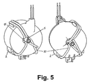
- Fig. 5 shows an oblique front and rear view of the Current transformer according to the second preferred embodiment, the fixing or guide grooves 15 of the guide pin 5 are recognizable. It can also be seen that in not all guide grooves in the second preferred embodiment 15 of the guide pin 5 or fixing grooves 2 occupied are.
- the current transformer housing 1 can thus be connected with the guide pin 5 for different embodiments can be used, making a flexible use is possible at a reduced cost.
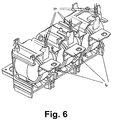
- Fig. 6 shows an arrangement of three current transformers according to the first embodiment as a three-pole current transformer in an interruption switching device in a cast housing is housed.
- the cast housing has openings through which the secondary outlet openings with the secondary conductors 14 and the primary terminals 4 are brought out.
- the other primary side Terminals 3 of the current transformers are electrically interconnected connected, so that for example a star configuration for a three-phase application.
- the fixing grooves 2 have a clamping function, the primary windings be clamped in the fixing grooves 2 so that easy assembly and additional fixation in radial Direction is achievable.
- the present invention does not apply to the specific configurations of the two preferred exemplary embodiments is limited.
- the main thought the invention lies in the lateral fixation of the primary side Windings with respect to the housing surface. This can also be done by other suitable measures, such as Gluing, guide holes or guide eyes, or changes in the surface of the housing that lead to a lateral fixation of the primary-side windings in their Lead position with respect to the housing 1.
- Even the shape of the case 1 is not limited to a torus shape, but other forms of housing are also conceivable in which the secondary winding is housed and on which the primary winding is wound up.
Landscapes
- Engineering & Computer Science (AREA)
- Power Engineering (AREA)
- Physics & Mathematics (AREA)
- General Physics & Mathematics (AREA)
- Transformers For Measuring Instruments (AREA)
- Measuring Instrument Details And Bridges, And Automatic Balancing Devices (AREA)
- Photoreceptors In Electrophotography (AREA)
- Cookers (AREA)
- Materials For Medical Uses (AREA)
- Table Equipment (AREA)
- Regulation Of General Use Transformers (AREA)
- Ignition Installations For Internal Combustion Engines (AREA)
- Coils Or Transformers For Communication (AREA)
Description
Claims (21)
- Messwandler mit einer Primärwicklung, einer Sekundärwicklung und einem Gehäuse (1) zum Aufnehmen der Sekundärwicklung, wobei die Primärwicklung auf die Außenseite des Gehäuses (1) und durch eine Öffnung des Gehäuses (1) gewickelt ist,
wobei der Messwandler eine Fixieranordnung (2, 5) zum seitlichen Fixieren der Lage der Wicklungen (10) der Primärwicklung bzgl. der Außenseite des Gehäuses (1) aufweist, dadurch gekennzeichnet dass die Fixieranordnung zusätzlich einen Führungsstift (5) zum Führen der Wicklungen der Primärwicklung umfasst, der als separates Teil in die Öffnung des Gehäuses einführbar ist und die Wicklungen (10) der Primärwicklung in der Öffnung des Gehäuses (1) fixiert. - Messwandler nach Anspruch 1, wobei die Fixieranordnung durch Fixiernuten (2) gebildet ist, die an der Außenseite des Gehäuses (1) angeordnet sind, und die Wicklungen (10) der Primärwicklung zumindest teilweise in den Fixiernuten (2) geführt sind.
- Messwandler nach Anspruch 2, wobei die Fixiernuten (2) eine Klemmfunktion zum Einklemmen der Wicklungen (10) der Primärwicklung aufweisen.
- Messwandler nach Anspruch 2 oder 3, wobei drei Gruppen von Fixiernuten (2) an unterschiedlichen Stellen auf der Außenseite des Gehäuses (1) angeordnet sind, so dass die in den Fixiernutengruppen geführten Wicklungen (10) verschiedener Gruppen einen vorbestimmten Winkel zueinander aufweisen.
- Messwandler nach einem der vorgenannten Ansprüche, wobei die Primärwicklung aus mehreren parallelgeschalteten Wicklungen (10) gebildet ist.
- Messwandler nach Anspruch 5, wobei drei Wicklungen (10) parallelgeschaltet sind und unter verschiedenen Winkeln auf dem Gehäuse (1) geführt sind.
- Messwandler nach Anspruch 5 oder 6, wobei die parallelgeschalteten Wicklungen (10) an einer Anschlussklemme (3, 4) elektrisch verbunden sind.
- Messwandler nach Anspruch 7, wobei die Anschlussklemme (3, 4) Fixierkerbungen (6, 7) aufweist zum Aufnehmen der Enden der Wicklungen (10).
- Messwandler nach Anspruch 8, wobei die Enden der parallelgeschalteten Wicklungen (10) durch in der Anschlussklemme (3, 4) gebildete Löcher geführt sind.
- Messwandler nach einem der vorgenannten Ansprüche, wobei das Gehäuse (1) ein zweiteiliges Kunststoffgehäuse ist, dessen beide Hälften steckbar verbunden sind.
- Messwandler nach Anspruch 10, wobei das Gehäuse (1) eine Torusform aufweist und die Wicklungen (10) der Primärwicklung um den Ringwulst der Torusform geführt und durch axiale Führungsnuten (2) auf dem Außenumfang des Ringwulstes in ihrer Lage seitlich fixiert sind.
- Messwandler nach Anspruch 11, wobei die Führungsnuten (2) gruppenweise auf dem Gehäuse (1) angeordnet sind.
- Messwandler nach Anspruch 12, wobei drei Gruppen der Führungsnuten (2) um einen vorbestimmten Winkel auf dem torusförmigen Gehäuse (1) voneinander beabstandet angeordnet sind.
- Messwandler nach Anspruch 1, wobei der Führungsstift (5) axiale Führungsnuten (15) zum Aufnahmen einzelner Wicklungen (10) aufweist.
- Messwandler nach Anspruch 1 oder 14, wobei der Führungsstift (5) an zumindest einer Stirnendfläche eine Ausrichtungskontur (11) aufweist, die in eine an einer Anschlussklemme (3, 4) eingebrachte Ausrichtungsöffnung (16) eingreift, um die Drehlage des Führungsstifts (5) bzgl. der Anschlussklemme (3, 4) festzulegen.
- Messwandler nach Anspruch 15, wobei die Wicklungen (10) der Primärwicklung an der Anschlussklemme (3, 4) befestigt sind.
- Messwandler nach einem der Ansprüche 11 bis 16, wobei die Gehäusehälften des torusförmigen Gehäuses (1) ineinander eingreifen, so dass ein Verdrehen der Gehäusehälften verhindert wird.
- Messwandler nach Anspruch 17, wobei eine Austrittsöffnung zum Hindurchführen der Sekundärwicklungsleiter (14) zweiteilig ausgebildet ist, wobei ein Teil (12) auf einer der Gehäusehälften angeordnet ist und der andere Teil (13) auf der anderen Gehäusehälfte, und wobei die Teile ineinandergreifen, so dass ein Verdrehen der Gehäusehälften verhindert wird.
- Verwendung eines Messwandlers nach einem der vorhergehenden Ansprüche als Stromwandler, dem ein Stromsignal zugeführt wird und der das Stromsignal umwandelt.
- Verwendung nach Anspruch 19, wobei drei Messwandler zu einem dreipoligen Stromwandler verschaltet sind.
- Verwendung eines Stromwandlers nach einem der Ansprüche 19 oder 20 in einer elektronischen Auslösevorrichtung.
Applications Claiming Priority (3)
| Application Number | Priority Date | Filing Date | Title |
|---|---|---|---|
| DE10013143A DE10013143C2 (de) | 2000-03-17 | 2000-03-17 | Messwandler |
| DE10013143 | 2000-03-17 | ||
| PCT/EP2001/003041 WO2001069271A2 (de) | 2000-03-17 | 2001-03-16 | Messwandler |
Publications (2)
| Publication Number | Publication Date |
|---|---|
| EP1266231A2 EP1266231A2 (de) | 2002-12-18 |
| EP1266231B1 true EP1266231B1 (de) | 2004-10-13 |
Family
ID=7635188
Family Applications (1)
| Application Number | Title | Priority Date | Filing Date |
|---|---|---|---|
| EP01915365A Expired - Lifetime EP1266231B1 (de) | 2000-03-17 | 2001-03-16 | Messwandler |
Country Status (8)
| Country | Link |
|---|---|
| EP (1) | EP1266231B1 (de) |
| CN (1) | CN1276261C (de) |
| AT (1) | ATE279732T1 (de) |
| DE (2) | DE10013143C2 (de) |
| ES (1) | ES2248297T3 (de) |
| PL (1) | PL202628B1 (de) |
| PT (1) | PT1266231E (de) |
| WO (1) | WO2001069271A2 (de) |
Families Citing this family (13)
| Publication number | Priority date | Publication date | Assignee | Title |
|---|---|---|---|---|
| DE10223995C1 (de) | 2002-05-29 | 2003-11-27 | Epcos Ag | Spulenkörper und Kerndrossel mit dem Spulenkörper |
| DE102004021835B4 (de) * | 2004-05-04 | 2006-05-11 | Tyco Electronics Amp Gmbh | Geräteklemme |
| DE102005047894B4 (de) * | 2005-10-06 | 2010-05-12 | Abb Ag | Verfahren zur Prüfung der Betriebsfähigkeit von Messumformern |
| IT1395697B1 (it) * | 2009-05-28 | 2012-10-19 | Abb Spa | Trasformatore di corrente, dispositivo di protezione comprendente tale trasformatore, e relativo interruttore |
| DE102013206453B4 (de) * | 2013-04-11 | 2015-02-12 | SUMIDA Components & Modules GmbH | Gehäuse mit verlängerten Kriech- und Luftstrecken und elektrisches Bauelement mit derartigem Gehäuse |
| DE102013213404A1 (de) * | 2013-07-09 | 2015-01-15 | Vacuumschmelze Gmbh & Co. Kg | Induktives Bauelement |
| US9939465B2 (en) * | 2015-04-24 | 2018-04-10 | Sumida Corporation | Electric current detector |
| DE102015216861A1 (de) * | 2015-09-03 | 2017-03-09 | Siemens Aktiengesellschaft | Aktivteileinheit eines Messwandlers und Messwandler |
| CN108878118B (zh) | 2017-05-08 | 2021-06-11 | 台达电子工业股份有限公司 | 变压器 |
| CN108878105B (zh) * | 2017-05-08 | 2021-07-30 | 台达电子工业股份有限公司 | 变压器 |
| EP3474024A1 (de) * | 2017-10-19 | 2019-04-24 | RITZ Instrument Transformers GmbH | Stromwandler mit fluid- oder ölpapierisolierung für hochspannung |
| AU2022489210A1 (en) * | 2022-12-13 | 2025-01-02 | Hager-Electro Sas | Differential measurement torus for an electrical differential protection apparatus and associated electrical differential protection apparatus |
| US20260094763A1 (en) * | 2024-09-30 | 2026-04-02 | Schneider Electric USA, Inc. | Enhanced differential sensor winding pattern |
Family Cites Families (5)
| Publication number | Priority date | Publication date | Assignee | Title |
|---|---|---|---|---|
| DE7728177U1 (de) * | 1977-09-12 | 1979-01-04 | Siemens Ag, 1000 Berlin Und 8000 Muenchen | Wandler, insbesondere summenstromwandler |
| US4500832A (en) * | 1983-02-28 | 1985-02-19 | Codman & Shurtleff, Inc. | Electrical transformer |
| FR2662014B1 (fr) * | 1990-05-10 | 1992-07-24 | Merlin Gerin | Transformateur homopolaire pour interrupteurs ou disjoncteurs differentiels et procede de montage. |
| DE4216248C2 (de) * | 1992-05-16 | 2000-05-18 | Abb Patent Gmbh | Aufnahmebehälter für einen Wandler für einen Fehlerstromschutzschalter und Wandler |
| FR2711838B1 (fr) * | 1993-10-25 | 1996-01-05 | Legrand Sa | Boîtier de tore, et tore bobiné comportant un tel boîtier. |
-
2000
- 2000-03-17 DE DE10013143A patent/DE10013143C2/de not_active Expired - Lifetime
-
2001
- 2001-03-16 EP EP01915365A patent/EP1266231B1/de not_active Expired - Lifetime
- 2001-03-16 PT PT01915365T patent/PT1266231E/pt unknown
- 2001-03-16 ES ES01915365T patent/ES2248297T3/es not_active Expired - Lifetime
- 2001-03-16 PL PL364497A patent/PL202628B1/pl unknown
- 2001-03-16 WO PCT/EP2001/003041 patent/WO2001069271A2/de not_active Ceased
- 2001-03-16 AT AT01915365T patent/ATE279732T1/de active
- 2001-03-16 CN CNB018066283A patent/CN1276261C/zh not_active Expired - Fee Related
- 2001-03-16 DE DE2001504108 patent/DE50104108D1/de not_active Expired - Lifetime
Also Published As
| Publication number | Publication date |
|---|---|
| EP1266231A2 (de) | 2002-12-18 |
| PL364497A1 (en) | 2004-12-13 |
| CN1276261C (zh) | 2006-09-20 |
| DE50104108D1 (de) | 2004-11-18 |
| PT1266231E (pt) | 2004-12-31 |
| DE10013143C2 (de) | 2002-06-27 |
| ATE279732T1 (de) | 2004-10-15 |
| ES2248297T3 (es) | 2006-03-16 |
| WO2001069271A3 (de) | 2001-12-20 |
| DE10013143A1 (de) | 2001-10-04 |
| PL202628B1 (pl) | 2009-07-31 |
| WO2001069271A2 (de) | 2001-09-20 |
| CN1418313A (zh) | 2003-05-14 |
Similar Documents
| Publication | Publication Date | Title |
|---|---|---|
| DE69105673T2 (de) | Transformator. | |
| DE2632886C3 (de) | Transformator | |
| DE2513498C3 (de) | Koaxiale Zwischenkupplung für Antennen-Koaxialkabel | |
| DE3543463A1 (de) | Stromfuehlertransformatoranordnung | |
| DE10013143C2 (de) | Messwandler | |
| DE69109369T2 (de) | Elektrische Spulenanordnung zur Verwendung als Transformator oder dergleichen. | |
| EP3096336B1 (de) | Induktives bauelement für leiterplattenmontage und wechselrichter mit einem leiterplattenmontierten induktiven bauelement | |
| DE102009026742A1 (de) | Stromwandlereinheit | |
| DE2823779C2 (de) | Transformator | |
| DE69628545T2 (de) | Anordnung zur festlegung eines elektrischen bauelements mit einem montagegrundkörper | |
| DE102015115410A1 (de) | Induktive Strommesswandlervorrichtung | |
| DE102015205632A1 (de) | Stromwandler und Strommesseinrichtung | |
| DE4119830B4 (de) | Kompakt-Schalter mit verschiedenen Nennströmen | |
| DE3029295A1 (de) | Elektrischer widerstand | |
| DE102022133141B3 (de) | Anschlussdose für ein Daten- und Kommunikationsnetz | |
| DE102018213519A1 (de) | Rogowskispule für einen Niederspannungsleistungsschalter | |
| EP1807847B1 (de) | Gehäuse | |
| EP0618451B1 (de) | Stromwandler, insbesondere für einen elektronischen Elektrizitätszähler | |
| DE2618288B2 (de) | Installations-Selbstschalter | |
| DE2904470C2 (de) | Einrichtung zur transformatorischen Einstellung der Spannung unter Last | |
| DE202008009101U1 (de) | Messwertgeber-Anordnung zur Kurzschlusserfassung in elektrischen Mittelspannungs-Schaltanlagen | |
| DE60118431T2 (de) | Elektrischer pol für einen niederspannungs-unterbrecherschalter | |
| DE2832449C2 (de) | Anschlußleiste sowie Verfahren zum Herstellen von Anschlüssen mit ihrer Hilfe | |
| DE19943734B4 (de) | Elektrischer Installationssteckverbinder mit einem Phasenwähler | |
| DE102022212200B4 (de) | Verdrahtungsmodul zur internen Kontaktierung eines Hilfsschalters, Verdrahtungssystem und Verfahren zum elektrischen Kontaktieren eines solchen Verdrahtungsmoduls |
Legal Events
| Date | Code | Title | Description |
|---|---|---|---|
| PUAI | Public reference made under article 153(3) epc to a published international application that has entered the european phase |
Free format text: ORIGINAL CODE: 0009012 |
|
| 17P | Request for examination filed |
Effective date: 20021016 |
|
| AK | Designated contracting states |
Kind code of ref document: A2 Designated state(s): AT BE CH CY DE DK ES FI FR GB GR IE IT LI LU MC NL PT SE TR |
|
| 17Q | First examination report despatched |
Effective date: 20030603 |
|
| GRAP | Despatch of communication of intention to grant a patent |
Free format text: ORIGINAL CODE: EPIDOSNIGR1 |
|
| GRAS | Grant fee paid |
Free format text: ORIGINAL CODE: EPIDOSNIGR3 |
|
| GRAA | (expected) grant |
Free format text: ORIGINAL CODE: 0009210 |
|
| AK | Designated contracting states |
Kind code of ref document: B1 Designated state(s): AT BE CH CY DE DK ES FI FR GB GR IE IT LI LU MC NL PT SE TR |
|
| PG25 | Lapsed in a contracting state [announced via postgrant information from national office to epo] |
Ref country code: GB Free format text: LAPSE BECAUSE OF FAILURE TO SUBMIT A TRANSLATION OF THE DESCRIPTION OR TO PAY THE FEE WITHIN THE PRESCRIBED TIME-LIMIT Effective date: 20041013 Ref country code: IE Free format text: LAPSE BECAUSE OF FAILURE TO SUBMIT A TRANSLATION OF THE DESCRIPTION OR TO PAY THE FEE WITHIN THE PRESCRIBED TIME-LIMIT Effective date: 20041013 |
|
| REG | Reference to a national code |
Ref country code: GB Ref legal event code: FG4D Free format text: NOT ENGLISH |
|
| REG | Reference to a national code |
Ref country code: CH Ref legal event code: EP |
|
| REG | Reference to a national code |
Ref country code: SE Ref legal event code: TRGR |
|
| REG | Reference to a national code |
Ref country code: IE Ref legal event code: FG4D Free format text: GERMAN |
|
| REF | Corresponds to: |
Ref document number: 50104108 Country of ref document: DE Date of ref document: 20041118 Kind code of ref document: P |
|
| REG | Reference to a national code |
Ref country code: PT Ref legal event code: SC4A Free format text: AVAILABILITY OF NATIONAL TRANSLATION Effective date: 20041103 |
|
| REG | Reference to a national code |
Ref country code: CH Ref legal event code: NV Representative=s name: RITSCHER & PARTNER AG |
|
| REG | Reference to a national code |
Ref country code: GR Ref legal event code: EP Ref document number: 20040404422 Country of ref document: GR |
|
| REG | Reference to a national code |
Ref country code: DK Ref legal event code: T3 |
|
| PG25 | Lapsed in a contracting state [announced via postgrant information from national office to epo] |
Ref country code: CY Free format text: LAPSE BECAUSE OF NON-PAYMENT OF DUE FEES Effective date: 20050316 |
|
| PGFP | Annual fee paid to national office [announced via postgrant information from national office to epo] |
Ref country code: GB Payment date: 20050329 Year of fee payment: 5 |
|
| PGFP | Annual fee paid to national office [announced via postgrant information from national office to epo] |
Ref country code: IE Payment date: 20050331 Year of fee payment: 5 |
|
| GBV | Gb: ep patent (uk) treated as always having been void in accordance with gb section 77(7)/1977 [no translation filed] |
Effective date: 20041013 |
|
| REG | Reference to a national code |
Ref country code: IE Ref legal event code: FD4D |
|
| ET | Fr: translation filed | ||
| PLBE | No opposition filed within time limit |
Free format text: ORIGINAL CODE: 0009261 |
|
| STAA | Information on the status of an ep patent application or granted ep patent |
Free format text: STATUS: NO OPPOSITION FILED WITHIN TIME LIMIT |
|
| 26N | No opposition filed |
Effective date: 20050714 |
|
| REG | Reference to a national code |
Ref country code: ES Ref legal event code: FG2A Ref document number: 2248297 Country of ref document: ES Kind code of ref document: T3 |
|
| REG | Reference to a national code |
Ref country code: CH Ref legal event code: PCAR Free format text: RITSCHER & PARTNER AG;RESIRAIN 1;8125 ZOLLIKERBERG (CH) |
|
| REG | Reference to a national code |
Ref country code: CH Ref legal event code: PFA Owner name: AEG NIEDERSPANNUNGSTECHNIK GMBH AND CO. KG, DE Free format text: FORMER OWNER: AEG NIEDERSPANNUNGSTECHNIK GMBH AND CO. KG, DE |
|
| REG | Reference to a national code |
Ref country code: FR Ref legal event code: PLFP Year of fee payment: 15 |
|
| PGFP | Annual fee paid to national office [announced via postgrant information from national office to epo] |
Ref country code: DK Payment date: 20150325 Year of fee payment: 15 Ref country code: MC Payment date: 20150305 Year of fee payment: 15 Ref country code: CH Payment date: 20150327 Year of fee payment: 15 Ref country code: IT Payment date: 20150325 Year of fee payment: 15 Ref country code: PT Payment date: 20150306 Year of fee payment: 15 Ref country code: NL Payment date: 20150326 Year of fee payment: 15 Ref country code: FI Payment date: 20150327 Year of fee payment: 15 Ref country code: ES Payment date: 20150326 Year of fee payment: 15 |
|
| PGFP | Annual fee paid to national office [announced via postgrant information from national office to epo] |
Ref country code: FR Payment date: 20150317 Year of fee payment: 15 Ref country code: LU Payment date: 20150402 Year of fee payment: 15 Ref country code: AT Payment date: 20150304 Year of fee payment: 15 Ref country code: GR Payment date: 20150330 Year of fee payment: 15 Ref country code: SE Payment date: 20150327 Year of fee payment: 15 Ref country code: TR Payment date: 20150306 Year of fee payment: 15 |
|
| PGFP | Annual fee paid to national office [announced via postgrant information from national office to epo] |
Ref country code: BE Payment date: 20150327 Year of fee payment: 15 |
|
| PG25 | Lapsed in a contracting state [announced via postgrant information from national office to epo] |
Ref country code: BE Free format text: LAPSE BECAUSE OF NON-PAYMENT OF DUE FEES Effective date: 20160331 |
|
| REG | Reference to a national code |
Ref country code: DK Ref legal event code: EBP Effective date: 20160331 |
|
| PG25 | Lapsed in a contracting state [announced via postgrant information from national office to epo] |
Ref country code: MC Free format text: LAPSE BECAUSE OF NON-PAYMENT OF DUE FEES Effective date: 20160331 Ref country code: FI Free format text: LAPSE BECAUSE OF NON-PAYMENT OF DUE FEES Effective date: 20160316 Ref country code: LU Free format text: LAPSE BECAUSE OF NON-PAYMENT OF DUE FEES Effective date: 20160316 |
|
| REG | Reference to a national code |
Ref country code: CH Ref legal event code: PL |
|
| REG | Reference to a national code |
Ref country code: SE Ref legal event code: EUG |
|
| REG | Reference to a national code |
Ref country code: AT Ref legal event code: MM01 Ref document number: 279732 Country of ref document: AT Kind code of ref document: T Effective date: 20160316 |
|
| REG | Reference to a national code |
Ref country code: NL Ref legal event code: MM Effective date: 20160401 |
|
| PG25 | Lapsed in a contracting state [announced via postgrant information from national office to epo] |
Ref country code: SE Free format text: LAPSE BECAUSE OF NON-PAYMENT OF DUE FEES Effective date: 20160317 Ref country code: PT Free format text: LAPSE BECAUSE OF NON-PAYMENT OF DUE FEES Effective date: 20160916 |
|
| REG | Reference to a national code |
Ref country code: FR Ref legal event code: ST Effective date: 20161130 |
|
| PG25 | Lapsed in a contracting state [announced via postgrant information from national office to epo] |
Ref country code: FR Free format text: LAPSE BECAUSE OF NON-PAYMENT OF DUE FEES Effective date: 20160331 Ref country code: LI Free format text: LAPSE BECAUSE OF NON-PAYMENT OF DUE FEES Effective date: 20160331 Ref country code: NL Free format text: LAPSE BECAUSE OF NON-PAYMENT OF DUE FEES Effective date: 20160401 Ref country code: CH Free format text: LAPSE BECAUSE OF NON-PAYMENT OF DUE FEES Effective date: 20160331 |
|
| REG | Reference to a national code |
Ref country code: GR Ref legal event code: ML Ref document number: 20040404422 Country of ref document: GR Effective date: 20161006 |
|
| PG25 | Lapsed in a contracting state [announced via postgrant information from national office to epo] |
Ref country code: GR Free format text: LAPSE BECAUSE OF NON-PAYMENT OF DUE FEES Effective date: 20161006 Ref country code: AT Free format text: LAPSE BECAUSE OF NON-PAYMENT OF DUE FEES Effective date: 20160316 Ref country code: IT Free format text: LAPSE BECAUSE OF NON-PAYMENT OF DUE FEES Effective date: 20160316 |
|
| REG | Reference to a national code |
Ref country code: ES Ref legal event code: FD2A Effective date: 20170428 |
|
| PG25 | Lapsed in a contracting state [announced via postgrant information from national office to epo] |
Ref country code: DK Free format text: LAPSE BECAUSE OF NON-PAYMENT OF DUE FEES Effective date: 20160331 |
|
| PG25 | Lapsed in a contracting state [announced via postgrant information from national office to epo] |
Ref country code: ES Free format text: LAPSE BECAUSE OF NON-PAYMENT OF DUE FEES Effective date: 20160317 |
|
| REG | Reference to a national code |
Ref country code: DE Ref legal event code: R081 Ref document number: 50104108 Country of ref document: DE Owner name: ABB SCHWEIZ AG, CH Free format text: FORMER OWNER: AEG NIEDERSPANNUNGSTECHNIK GMBH & CO KG, 24534 NEUMUENSTER, DE Ref country code: DE Ref legal event code: R082 Ref document number: 50104108 Country of ref document: DE Representative=s name: PRINZ & PARTNER MBB PATENTANWAELTE RECHTSANWAE, DE Ref country code: DE Ref legal event code: R082 Ref document number: 50104108 Country of ref document: DE Representative=s name: TBK, DE Ref country code: DE Ref legal event code: R081 Ref document number: 50104108 Country of ref document: DE Owner name: GE CONSUMER & INDUSTRIAL GMBH, DE Free format text: FORMER OWNER: AEG NIEDERSPANNUNGSTECHNIK GMBH & CO KG, 24534 NEUMUENSTER, DE |
|
| PGFP | Annual fee paid to national office [announced via postgrant information from national office to epo] |
Ref country code: DE Payment date: 20190321 Year of fee payment: 19 |
|
| REG | Reference to a national code |
Ref country code: DE Ref legal event code: R119 Ref document number: 50104108 Country of ref document: DE |
|
| REG | Reference to a national code |
Ref country code: DE Ref legal event code: R082 Ref document number: 50104108 Country of ref document: DE Representative=s name: PRINZ & PARTNER MBB PATENTANWAELTE RECHTSANWAE, DE Ref country code: DE Ref legal event code: R081 Ref document number: 50104108 Country of ref document: DE Owner name: ABB SCHWEIZ AG, CH Free format text: FORMER OWNER: GE CONSUMER & INDUSTRIAL GMBH, 24536 NEUMUENSTER, DE |
|
| PG25 | Lapsed in a contracting state [announced via postgrant information from national office to epo] |
Ref country code: DE Free format text: LAPSE BECAUSE OF NON-PAYMENT OF DUE FEES Effective date: 20201001 |
|
| PG25 | Lapsed in a contracting state [announced via postgrant information from national office to epo] |
Ref country code: TR Free format text: LAPSE BECAUSE OF NON-PAYMENT OF DUE FEES Effective date: 20160316 |