EP1266231B1 - Instrument transformer - Google Patents
Instrument transformer Download PDFInfo
- Publication number
- EP1266231B1 EP1266231B1 EP01915365A EP01915365A EP1266231B1 EP 1266231 B1 EP1266231 B1 EP 1266231B1 EP 01915365 A EP01915365 A EP 01915365A EP 01915365 A EP01915365 A EP 01915365A EP 1266231 B1 EP1266231 B1 EP 1266231B1
- Authority
- EP
- European Patent Office
- Prior art keywords
- housing
- accordance
- windings
- measuring transformer
- primary winding
- Prior art date
- Legal status (The legal status is an assumption and is not a legal conclusion. Google has not performed a legal analysis and makes no representation as to the accuracy of the status listed.)
- Expired - Lifetime
Links
Images


Classifications
-
- H—ELECTRICITY
- H01—ELECTRIC ELEMENTS
- H01F—MAGNETS; INDUCTANCES; TRANSFORMERS; SELECTION OF MATERIALS FOR THEIR MAGNETIC PROPERTIES
- H01F38/00—Adaptations of transformers or inductances for specific applications or functions
- H01F38/20—Instruments transformers
- H01F38/22—Instruments transformers for single phase ac
- H01F38/28—Current transformers
- H01F38/30—Constructions
-
- G—PHYSICS
- G01—MEASURING; TESTING
- G01R—MEASURING ELECTRIC VARIABLES; MEASURING MAGNETIC VARIABLES
- G01R15/00—Details of measuring arrangements of the types provided for in groups G01R17/00 - G01R29/00, G01R33/00 - G01R33/26 or G01R35/00
- G01R15/14—Adaptations providing voltage or current isolation, e.g. for high-voltage or high-current networks
- G01R15/18—Adaptations providing voltage or current isolation, e.g. for high-voltage or high-current networks using inductive devices, e.g. transformers
- G01R15/183—Adaptations providing voltage or current isolation, e.g. for high-voltage or high-current networks using inductive devices, e.g. transformers using transformers with a magnetic core
Definitions
- the invention relates to a transducer with a Primary winding, a secondary winding and a housing for receiving the secondary winding, the primary winding is wound on the outside of the housing.
- Measuring transformers are transformers to which measuring devices are connected. Voltage meters are connected to voltage transformers or voltage paths from measuring devices to current transformers Ammeter or current paths.
- Voltage converters are mostly used in high voltage systems, to keep the high voltage away from the measuring station.
- the Voltage transformers are connected in the same way as the connection of a transformer.
- Current transformers are used in low voltage systems To be able to use measuring instruments with a small measuring range.
- Current transformers are used in high-voltage systems even with weak currents, around the high voltage from the measuring station keep. With the current transformer, the input or Primary winding connected in series with the consumer. The entire load or mains current then flows through the primary winding. The mains current and the current in the through the Ammeter almost short-circuited output or secondary winding behave in the opposite way to the number of turns.
- the magnetic flux density in the iron core is included very low because both floods are opposite Create fields of equal strength.
- Current transformers are used, for example, to measure current in electronic release devices used by means of which an interrupter contact, for example a protective circuit is controlled.
- electronic release devices for low current levels of 25 A or less are primary multiple windings required to be sufficient Ensure flooding.
- magnetic forces i.e. Lorenz forces
- the lateral fixation with respect to the housing can be achieved by fixing grooves on the outside of the Housing are arranged, the windings of the Primary winding at least partially performed in the fixing grooves are. Due to the fixing grooves there is a lateral shift and thus avoid damage to the windings.
- the Fixing grooves can, for example, a clamping function Pinching the windings, so that an additional Fixation in the vertical direction is ensured. Thereby assembly can be simplified, for example.
- the primary winding can consist of several connected in parallel Windings be formed. This leads to a minor Overall diameter of the primary winding and a sufficient one Flexibility of the primary winding leader. Furthermore, by this design ensures that the primary windings have a sufficiently small diameter to a toroidal housing through the central opening of the Torus to be led. For example, three Windings can be connected in parallel, this under different angles are guided on the housing.
- the parallel windings can be connected to one Terminal that, for example, for feeding the Primary current is used to be electrically connected.
- the housing can be, for example, a two-part Be plastic housing, the two halves of which are pluggably connected. This way is an easy one Secondary winding possible. If the case has a toroidal shape, the windings of the Primary winding led around the torus shape and through axial guide grooves on the outer circumference of the Ring bead be fixed.
- the guide grooves can be arranged in groups on the housing. So can for example three groups of guide grooves in one predetermined angular distance on the toroidal housing be arranged. Through this spaced arrangement of Guide groove groups can with high limit currents occurring forces are balanced so that a Damage to the entire transducer arrangement avoided becomes.
- a guide pin for guiding the windings which can be inserted as a separate part into the opening of the housing is arranged.
- This guide pin preferably has axial guide grooves for receiving individual windings. This will additionally fix the windings in the ensured middle opening of the toroidal housing.
- the guide pin on at least one End face have an alignment contour that in a to a connection terminal for connecting the transducer the alignment hole introduced in the circuit to be measured engages with respect to the rotational position of the guide pin of the connection terminal.
- the windings of the primary winding are also direct attached to the connection terminal (e.g. soldered).
- the housing halves of the toroidal housing can preferably be designed so that they interlock so that twisting of the housing halves is prevented becomes. This can be achieved by having a Exit opening for the passage of the secondary winding conductors is formed in two parts, one part on one the housing halves is arranged and the other part the other half of the housing, and the two parts interlock, so that twisting the housing halves is prevented. This enables a predetermined positional relationship between the outlet of the secondary winding conductors and the connection terminals are ensured.
- Fig. 1 shows a partially exploded view of the current transformer according to the first preferred embodiment.
- a current transformer is for example for rated current of 25A and includes a bowl-shaped Housing 1, in which, for example, on an annular Core material wound secondary winding housed is.
- the winding conductor 14 of the secondary winding are through an outlet opening arranged on the housing 1 led to the outside.
- multiple primary windings 10 are required which in groups at a certain angular distance to the Housing 1 are wound.
- the windings 10 of the primary winding are 2 in their by guide or fixing grooves Position with respect to the housing 1 fixed laterally.
- the fixing grooves 2 are arranged on the surface of the housing, for example by appropriate design of the mold of the plastic housing, through appropriate processing the surface of the housing, or by fixing (for example gluing) appropriate structures the housing surface.
- the primary windings 10 consist of three individual winding conductors and thus each have three ends that to a respective connection terminal 3 or 4 for connection of the current path to be measured are attached.
- the attachment happens by the three single conductors corresponding through openings in the connecting terminals 3 or 4 and then in corresponding notches 6 or 7 can be bent.
- simplified soldering is possible, with the solder joints are subject to low voltages.
- To the required Achieving current carrying capacity is a certain cross section the primary winding line is required.
- Such a Cross section leads however due to the reduced Flexibility of the leader on difficult handling and accommodating three primary windings in the middle Opening of the toroidal housing shown in Fig. 1 can not. Therefore, the three single winding leaders used with a correspondingly reduced cross section and at terminals 3 and 4 as a parallel connection electrically connected. This enables greater flexibility the winding conductor with reduced space requirement in the middle opening of the toroidal housing.
- a Guide pin 5 in the middle opening of the toroidal Housing 1 arranged through which the windings also on the the side of the annular bead opposite the fixing grooves of the toroidal housing 1 are guided or fixed. This can be done, for example, through guide grooves explained later of the guide pin 5 can be achieved.
- the housing 1 has a holding base 8, which at Installation in a recess in a mounting plate 9 is introduced.
- Fig. 2 shows an oblique front and rear view of the Current converter according to the first preferred embodiment without terminals 3 and 4.
- the Alignment contour can be designed accordingly a mold or by machining the surface of the Guide pin 5 are made.
- the two alignment contours 11 are a perfect match with those in the connection terminals 3 and 4 arranged alignment openings 16 configured.
- the alignment contour 11 can also be provided only on one end face. at the assembly of the terminals 3 and 4 can thus predetermined positional or rotational positional relationship between the guide pin 5 and the connecting terminals 3 and 4 become. This relationship can be so, for example be chosen that the outlet opening for the secondary conductors 14 perpendicular to the connection surface of the connection terminal 4 is arranged.
- the outlet opening for the secondary conductor 14 is in two parts formed, wherein a channel-shaped part 12 is arranged on one housing half and one in the channel-shaped part 12 engaging part 13 as a channel closure with two outlet openings for the two ends the secondary conductor 14 is formed.
- the two housing halves can be pushed or pushed into each other, the closing part 13 of the outlet opening in the engages channel-shaped part 12, so that a twisting of the prevented two nested housing halves becomes. This also provides strain relief reached.
- the fixing grooves 2 are arranged in groups that one have a predetermined angular distance.
- the groups can for example at equal angular intervals of 120 ° on the Surface of the toroidal housing 1 may be arranged. in the present case of the first preferred embodiment an uneven angular distribution is provided.
- the optimal angular arrangement of the fixing groove groups for best possible compensation of the displacement forces can be measured be determined.
- Fig. 3 shows a separate representation of the guide pin 5, in the middle opening of the toroidal housing 1 is arranged.
- the guide pin points 5 guide grooves 15 in which the primary side Windings are performed. So the windings can too on the inside of the toroidal housing 1 guided or fixed.
- the alignment contours 11 On the two ends of the Guide pin 5 shown in Fig. 3 are the alignment contours 11 recognizable.
- the Current converter according to the second preferred embodiment has essentially the same structure as that of first preferred embodiment.
- the current transformer according to the second preferred embodiment only one primary winding conductor due to the lower nominal current required, but with four windings 10 are provided at predetermined angular intervals.
- two of the windings 10 form a group summarized and the other two in predetermined Angular distances to the group.
- the single primary winding leader is by one of the in the connection terminals 3 and 4 arranged openings and led into a the fixing notches 7 bent and soldered.
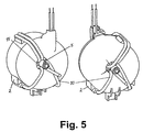
- Fig. 5 shows an oblique front and rear view of the Current transformer according to the second preferred embodiment, the fixing or guide grooves 15 of the guide pin 5 are recognizable. It can also be seen that in not all guide grooves in the second preferred embodiment 15 of the guide pin 5 or fixing grooves 2 occupied are.
- the current transformer housing 1 can thus be connected with the guide pin 5 for different embodiments can be used, making a flexible use is possible at a reduced cost.
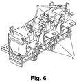
- Fig. 6 shows an arrangement of three current transformers according to the first embodiment as a three-pole current transformer in an interruption switching device in a cast housing is housed.
- the cast housing has openings through which the secondary outlet openings with the secondary conductors 14 and the primary terminals 4 are brought out.
- the other primary side Terminals 3 of the current transformers are electrically interconnected connected, so that for example a star configuration for a three-phase application.
- the fixing grooves 2 have a clamping function, the primary windings be clamped in the fixing grooves 2 so that easy assembly and additional fixation in radial Direction is achievable.
- the present invention does not apply to the specific configurations of the two preferred exemplary embodiments is limited.
- the main thought the invention lies in the lateral fixation of the primary side Windings with respect to the housing surface. This can also be done by other suitable measures, such as Gluing, guide holes or guide eyes, or changes in the surface of the housing that lead to a lateral fixation of the primary-side windings in their Lead position with respect to the housing 1.
- Even the shape of the case 1 is not limited to a torus shape, but other forms of housing are also conceivable in which the secondary winding is housed and on which the primary winding is wound up.
Abstract
Description
Die Erfindung bezieht sich auf einen Messwandler mit einer Primärwicklung, einer Sekundärwicklung und einem Gehäuse zum Aufnehmen der Sekundärwicklung, wobei die Primärwicklung auf die Außenseite des Gehäuses gewickelt ist.The invention relates to a transducer with a Primary winding, a secondary winding and a housing for receiving the secondary winding, the primary winding is wound on the outside of the housing.
Messwandler sind Transformatoren, an die man Messgeräte anschließt. An Spannungswandler schließt man Spannungsmesser oder Spannungspfade von Messgeräten an, an Stromwandler Strommesser oder Strompfade.Measuring transformers are transformers to which measuring devices are connected. Voltage meters are connected to voltage transformers or voltage paths from measuring devices to current transformers Ammeter or current paths.
Spannungswandler werden meist in Hochspannungsanlagen verwendet, um die Hochspannung vom Messplatz fernzuhalten. Der Anschluss von Spannungswandlern erfolgt wie der Anschluss eines Transformators.Voltage converters are mostly used in high voltage systems, to keep the high voltage away from the measuring station. The Voltage transformers are connected in the same way as the connection of a transformer.
Stromwandler werden in Niederspannungsanlagen verwendet, um Messinstrumente mit kleinem Messbereich einsetzen zu können. In Hochspannungsanlagen verwendet man Stromwandler auch bei schwachen Strömen, um die Hochspannung vom Messplatz fernzuhalten. Beim Stromwandler ist die Eingangs- oder Primärwicklung in Reihe mit dem Verbraucher geschaltet. Der gesamte Last- oder Netzstrom fließt dann durch die Primärwicklung. Der Netzstrom und der Strom in der durch den Strommesser nahezu kurzgeschlossenen Ausgangs- oder Sekundärwicklung verhalten sich umgekehrt wie die Windungszahlen. Die magnetische Flussdichte im Eisenkern ist dabei sehr gering, weil beide Durchflutungen entgegengesetzte Felder gleicher Stärke hervorrufen. Current transformers are used in low voltage systems To be able to use measuring instruments with a small measuring range. Current transformers are used in high-voltage systems even with weak currents, around the high voltage from the measuring station keep. With the current transformer, the input or Primary winding connected in series with the consumer. The entire load or mains current then flows through the primary winding. The mains current and the current in the through the Ammeter almost short-circuited output or secondary winding behave in the opposite way to the number of turns. The magnetic flux density in the iron core is included very low because both floods are opposite Create fields of equal strength.
Stromwandler werden beispielsweise zur Strommessung in elektronischen Auslösevorrichtungen verwendet, mittels denen ein Unterbrecherkontakt beispielsweise einer Schutzschaltung gesteuert wird. In elektronischen Auslöseeinrichtungen für niedrige Strompegel von 25 A oder weniger sind primärseitig mehrere Wicklungen erforderlich, um eine ausreichende Durchflutung sicherzustellen. Im Falle eines Kurzschlusses treten primärseitig hohe Kurzschluss- oder Grenzströme auf, wobei die dann auf die Primärwicklungen einwirkenden magnetischen Kräfte (d. h. Lorenzkräfte) so groß werden, dass sich die Wicklungen gegenseitig verschieben, was zu Beschädigungen führen kann.Current transformers are used, for example, to measure current in electronic release devices used by means of which an interrupter contact, for example a protective circuit is controlled. In electronic release devices for low current levels of 25 A or less are primary multiple windings required to be sufficient Ensure flooding. In the event of a short circuit high short-circuit or limit currents occur on the primary side, which then act on the primary windings magnetic forces (i.e. Lorenz forces) become so large that the windings shift each other, causing too Can cause damage.
Stromwandler oder andere Messwandler mit mehreren Primärwicklungen, die einen maximal auftretenden primärseitigen Durchlassgrenzstrom ohne Beschädigung überstehen können, sind somit wünschenswert.Current transformers or other measuring transformers with several Primary windings that have a maximum occurring primary-side forward limit current without damage can survive are therefore desirable.
In der Druckschrift EP-A-0 456 583 ist ein homopolarer Transformator gezeigt, der ein Gehäuse mit auf der Außenseite angeordneten Vertiefungen aufweist, in die Wicklungen der Primärwicklung aufgenommen werden.In document EP-A-0 456 583 there is a homopolar Transformer shown with a housing on the outside arranged recesses, in the windings of the Primary winding to be included.
Es ist eine Aufgabe der vorliegenden Erfindung, einen Messwandler der eingangs genannten Art mit hoher Stromtragfähigkeit bereitzustellen.It is an object of the present invention to provide a Transducers of the type mentioned at the beginning with high To provide current carrying capacity.
Diese Aufgabe wird gelöst durch einen Messwandler gemäss
Patentanspruch 1.This task is solved by a transducer according to
Durch die seitliche Fixierung der Wicklungen der Primärwicklung bzgl. des Gehäuses ist ein gegenseitiges Verschieben der einzelnen Wicklungen aufgrund der durch den hohen Primärstrom hervorgerufenen Ablenkkräfte nicht mehr möglich, so dass eine Beschädigung der Primärwicklungen auch bei hohen Grenzströmen vermieden werden kann.Due to the lateral fixation of the windings of the Primary winding with respect to the housing is mutual Moving the individual windings due to the high primary current caused deflection forces no longer possible, so damage to the primary windings too can be avoided at high limit currents.
Vorzugsweise kann die seitliche Fixierung bzgl. des Gehäuses durch Fixiernuten erzielt werden, die an der Außenseite des Gehäuses angeordnet sind, wobei die Wicklungen der Primärwicklung zumindest teilweise in den Fixiernuten geführt sind. Durch die Fixiernuten wird eine seitliche Verschiebung und damit Beschädigung der Wicklungen vermieden. Die Fixiernuten können beispielsweise eine Klemmfunktion zum Einklemmen der Wicklungen aufweisen, so dass eine zusätzliche Fixierung in vertikaler Richtung sichergestellt ist. Dadurch kann beispielsweise die Montage vereinfacht werden.Preferably, the lateral fixation with respect to the housing can be achieved by fixing grooves on the outside of the Housing are arranged, the windings of the Primary winding at least partially performed in the fixing grooves are. Due to the fixing grooves there is a lateral shift and thus avoid damage to the windings. The Fixing grooves can, for example, a clamping function Pinching the windings, so that an additional Fixation in the vertical direction is ensured. Thereby assembly can be simplified, for example.
Es können drei Gruppen von Fixiernuten an unterschiedlichen Stellen auf der Außenseite des Gehäuses angeordnet sein, so dass die in den Fixiernutengruppen geführten Wicklungen verschiedener Gruppen einen vorbestimmten Winkel zueinander aufweisen. Durch diese Beabstandung der Primärwicklungen auf dem Gehäuse kann eine verbesserte Verteilung der auf den Messwandler einwirkenden Kräfte erreicht werden.There can be three groups of fixing grooves on different Places can be arranged on the outside of the housing, so that the windings in the fixing groove groups different groups a predetermined angle to each other exhibit. Due to this spacing of the primary windings the housing can have an improved distribution on the Transducers acting forces can be achieved.
Die Primärwicklung kann aus mehreren parallelgeschalteten Wicklungen gebildet sein. Dies führt zu einem geringen Gesamtdurchmesser der Primärwicklung und einer ausreichenden Flexibilität des Primärwicklungsleiters. Ferner wird durch diese Ausgestaltung sichergestellt, dass die Primärwicklungen einen ausreichend geringen Durchmesser aufweisen, um bei einem torusförmigen Gehäuse durch die mittlere Öffnung des Torus geführt werden zu können. Es können beispielsweise drei Wicklungen parallelgeschaltet sein, wobei diese unter verschiedenen Winkeln auf dem Gehäuse geführt sind. Die parallelgeschalteten Wicklungen können an einer Anschlussklemme, die beispielsweise zum Zuführen des Primärstroms verwendet wird, elektrisch verbunden sein. Dabei kann die Anschlussklemme Fixierkerbungen aufweisen, zum Aufnehmen der Enden der Wicklungen. Ferner können Löcher in der Anschlussklemme gebildet sein, durch die die Enden der Wicklungen geführt sind. Die Durchführung der Leitungsenden durch die Löcher und das anschließende Umbiegen der Enden in die Fixierkerbungen ermöglicht ein einfaches Anlöten der Wicklungsenden, wobei die auf die Lötverbindungen wirkenden Spannungen verringert sind.The primary winding can consist of several connected in parallel Windings be formed. This leads to a minor Overall diameter of the primary winding and a sufficient one Flexibility of the primary winding leader. Furthermore, by this design ensures that the primary windings have a sufficiently small diameter to a toroidal housing through the central opening of the Torus to be led. For example, three Windings can be connected in parallel, this under different angles are guided on the housing. The parallel windings can be connected to one Terminal that, for example, for feeding the Primary current is used to be electrically connected. there can have the connecting clamp fixing notches for Pick up the ends of the windings. Furthermore, holes in be formed by the terminal through which the ends of the Windings are guided. The implementation of the line ends through the holes and then bending the ends in the fixing notches enables easy soldering of the Winding ends, with those acting on the solder connections Tensions are reduced.
Das Gehäuse kann beispielsweise durch ein zweitteiliges Kunststoffgehäuse gebildet sein, wobei dessen beiden Hälften steckbar verbunden sind. Auf diese Weise ist ein einfaches Einbringen der Sekundärwicklung möglich. Falls das Gehäuse eine Torusform aufweist, können die Wicklungen der Primärwicklung um den Ringwulst der Torusform geführt und durch axiale Führungsnuten auf dem Außenumfang des Ringwulstes fixiert sein. Die Führungsnuten können gruppenweise auf dem Gehäuse angeordnet sein. So können beispielsweise drei Gruppen der Führungsnuten in einem vorbestimmten Winkelabstand auf dem torusförmigen Gehäuse angeordnet sein. Durch diese beabstandete Anordnung der Führungsnutengruppen können die bei hohen Grenzströmen auftretenden Kräfte ausgeglichen werden, so dass eine Beschädigung der gesamten Messwandleranordnung vermieden wird.The housing can be, for example, a two-part Be plastic housing, the two halves of which are pluggably connected. This way is an easy one Secondary winding possible. If the case has a toroidal shape, the windings of the Primary winding led around the torus shape and through axial guide grooves on the outer circumference of the Ring bead be fixed. The guide grooves can be arranged in groups on the housing. So can for example three groups of guide grooves in one predetermined angular distance on the toroidal housing be arranged. Through this spaced arrangement of Guide groove groups can with high limit currents occurring forces are balanced so that a Damage to the entire transducer arrangement avoided becomes.
In der mittleren Öffnung des torusfömigen Gehäuses wird erfindungsgemäß ein Führungsstift zum Führen der Wicklungen, der als separates Teil in die Öffnung des Gehäuses einführbar ist, angeordnet. Dieser Führungsstift weist vorzugsweise axiale Führungsnuten zum Aufnehmen einzelner Wicklungen auf. Dadurch wird eine zusätzliche Fixierung der Wicklungen in der mittleren Öffnung des torusförmigen Gehäuses sichergestellt. Des weiteren kann der Führungsstift an zumindest einer Stirnendfläche eine Ausrichtungskontur aufweisen, die in eine an einer Anschlussklemme zum Anschließen des Messwandlers an den zu messenden Schaltkreis eingebrachte Ausrichtungsöffnung eingreift, um die Drehlage des Führungsstifts bezüglich der Anschlussklemme festzulegen. Dadurch kann ein funktionsgerechter Zusammenbau sichergestellt werden. Vorzugsweise werden auch die Wicklungen der Primärwicklung direkt an der Anschlussklemme befestigt (z.B. angelötet).In the middle opening of the toroidal housing according to the invention a guide pin for guiding the windings, which can be inserted as a separate part into the opening of the housing is arranged. This guide pin preferably has axial guide grooves for receiving individual windings. This will additionally fix the windings in the ensured middle opening of the toroidal housing. Furthermore, the guide pin on at least one End face have an alignment contour that in a to a connection terminal for connecting the transducer the alignment hole introduced in the circuit to be measured engages with respect to the rotational position of the guide pin of the connection terminal. This can be a functional assembly can be ensured. Preferably the windings of the primary winding are also direct attached to the connection terminal (e.g. soldered).
Die Gehäusehälften des torusförmigen Gehäuses können vorzugsweise so ausgestaltet sein, dass sie ineinander eingreifen, so dass eine Verdrehung der Gehäusehälften verhindert wird. Dies kann dadurch erreicht werden, dass eine Austrittsöffnung zum Hindurchführen der Sekundärwicklungsleiter zweiteilig ausgebildet ist, wobei ein Teil auf einer der Gehäusehälften angeordnet ist und der andere Teil auf der anderen Gehäusehälfte, und wobei die beiden Teile ineinandergreifen, so dass ein Verdrehen der Gehäusehälften verhindert wird. Dadurch kann eine vorbestimmte Lagebeziehung zwischen der Austrittsöffnung der Sekundärwicklungsleiter und den Anschlussklemmen sichergestellt werden.The housing halves of the toroidal housing can preferably be designed so that they interlock so that twisting of the housing halves is prevented becomes. This can be achieved by having a Exit opening for the passage of the secondary winding conductors is formed in two parts, one part on one the housing halves is arranged and the other part the other half of the housing, and the two parts interlock, so that twisting the housing halves is prevented. This enables a predetermined positional relationship between the outlet of the secondary winding conductors and the connection terminals are ensured.
Weitere vorteilhafte Weiterbildungen der vorgenannten Erfindung sind in den Unteransprüchen angegeben.Further advantageous developments of the aforementioned invention are specified in the subclaims.
Nachfolgend wird die Erfindung anhand von Ausführungsbeispielen
unter Bezugnahme auf die Zeichnungen näher erläutert.
Es zeigen:
Im Folgenden wird ein erstes bevorzugtes Ausführungsbeispiel eines als Stromwandler eingesetzten Messwandlers unter Bezugnahme auf die Figuren 1 bis 3 erläutert.The following is a first preferred embodiment of a measuring transformer used as a current transformer Explained with reference to Figures 1 to 3.
Fig. 1 zeigt eine teilweise auseinandergezogene Darstellung
des Stromwandlers gemäß dem ersten bevorzugten Ausführungsbeispiel.
Ein solcher Stromwandler ist beispielsweise für
einen Nennstrom von 25A vorgesehen und umfasst ein schalenförmiges
Gehäuse 1, in dem die beispielsweise auf ein ringförmiges
Kernmaterial aufgewickelte Sekundärwicklung untergebracht
ist. Die Wicklungsleiter 14 der Sekundärwicklung
sind durch eine an dem Gehäuse 1 angeordnete Austrittsöffnung
nach außen geführt. Für den relativ geringen Nennstrom
von 25A sind mehrere Primärwicklungen 10 erforderlich, die
gruppenweise unter einem bestimmten Winkelabstand auf das
Gehäuse 1 aufgewickelt sind. Die Wicklungen 10 der Primärwicklung
sind durch Führungs- oder Fixiernuten 2 in ihrer
Lage bezüglich des Gehäuses 1 seitlich fixiert. Die Fixiernuten
2 sind auf der Oberfläche des Gehäuses angeordnet,
beispielsweise durch entsprechende Ausgestaltung der Gussform
des Kunststoffgehäuses, durch entsprechende Bearbeitung
der Gehaüseoberfläche, oder durch Fixieren
(beispielsweise Aufkleben) entsprechender Strukturen auf
der Gehäuseoberfläche.Fig. 1 shows a partially exploded view
of the current transformer according to the first preferred embodiment.
Such a current transformer is for example for
rated current of 25A and includes a bowl-shaped
Die Primärwicklungen 10 bestehen aus drei einzelnen Wicklungsleitern
und weisen somit jeweils drei Enden auf, die
an einer jeweiligen Anschlussklemme 3 bzw. 4 zum Anschließen
des zu messenden Strompfads befestigt sind. Die Befestigung
geschieht dadurch, dass die drei Einzelleiter durch
entsprechende Durchgangsöffnungen in den Anschlussklemmen 3
bzw. 4 durchgeführt werden und danach in entsprechende Fixierkerbungen
6 bzw. 7 gebogen werden. Durch diese Maßnahme.
ist ein vereinfachtes Anlöten möglich, wobei die Lötstellen
geringen Spannungen unterworfen sind. Um die geforderte
Stromtragfähigkeit zu erzielen, ist ein bestimmter Querschnitt
der Primärwicklungsleitung erforderlich. Ein solcher
Querschnitt führt jedoch aufgrund der verringerten
Flexibilität des Leiters zu einer schwierigen Handhabung
und ein Unterbringen dreier Primärwicklungen in der mittleren
Öffnung des in Fig. 1 gezeigten torusförmigen Gehäuses
ist nicht möglich. Daher werden die drei Einzelwicklungsleiter
mit entsprechend verringertem Querschnitt verwendet
und an den Anschlussklemmen 3 und 4 als Parallelschaltung
elektrisch verbunden. Dies ermöglicht eine höhere Flexibilität
der Wicklungsleiter bei verringertem Platzbedarf in
der mittleren Öffnung des torusförmigen Gehäuses.The
Zur Verbesserung der Führung der Primärwicklungen ist ein
Führungsstift 5 in der mittleren Öffnung des torusförmigen
Gehäuses 1 angeordnet, durch den die Wicklungen auch an der
den Fixiernuten gegenüberliegenden Seite des Ringwulstes
des torusförmigen Gehäuses 1 geführt bzw. fixiert sind.
Dies kann beispielsweise durch später erläuterte Führungsnuten
des Führungsstifts 5 erzielt werden.To improve the guidance of the primary windings is a
Das Gehäuse 1 weist einen Haltesockel 8 auf, der bei der
Montage in eine in einer Haltplatte eingebrachte Halteaussparung
9 eingeführt wird.The
Fig. 2 zeigt eine schräge Vorder- und Rückansicht des
Stromwandlers gemäß dem ersten bevorzugten Ausführungsbeispiel
ohne die Anschlussklemmen 3 und 4. In dieser Darstellung
ist eine an den beiden Stirnendflächen des Führungsstifts
5 angeordnete Ausrichtungskontur 11 erkennbar. Die
Ausrichtungskontur kann durch entsprechende Ausgestaltung
einer Gussform oder durch Bearbeitung der Oberfläche des
Führungsstifts 5 hergestellt werden. Die beiden Ausrichtungskonturen
11 sind passgenau mit den in den Anschlussklemmen
3 und 4 angeordneten Ausrichtungsöffnungen 16 ausgestaltet.
Selbstverständlich kann die Ausrichtungskontur
11 auch nur an einer Stirnendfläche vorgesehen sein. Bei
der Montage der Anschlussklemmen 3 und 4 kann somit eine
vorbestimmte Lage- oder Drehlagebeziehung zwischen dem Führungsstift
5 und den Anschlussklemmen 3 und 4 sichergestellt
werden. Diese Lagebeziehung kann beispielsweise so
gewählt werden, dass die Austrittsöffnung für die Sekundärleiter
14 senkrecht zur Anschlussfläche der Anschlussklemme
4 angeordnet ist.Fig. 2 shows an oblique front and rear view of the
Current converter according to the first preferred embodiment
without
Die Austrittsöffnung für die Sekundärleiter 14 ist zweiteilig
ausgebildet, wobei ein kanalförmig ausgebildeter Teil
12 an der einen Gehäusehälfte angeordnet ist und ein in den
kanalförmigen Teil 12 eingreifender Teil 13 als Kanalverschluss
mit zwei Austrittsöffnungen für die beiden Enden
der Sekundärleiter 14 ausgebildet ist. Die beiden Gehäusehälften
können ineinander geschoben oder gesteckt werden,
wobei der schließende Teil 13 der Austrittsöffnung in den
kanalförmigen Teil 12 eingreift, so dass ein Verdrehen der
beiden ineinandergeschobenen Gehäusehälften verhindert
wird. Hierdurch wird gleichzeitig auch eine Zugentlastung
erreicht.The outlet opening for the
Beim Vorliegen des maximalen primärseitigen Grenzstroms
(beispielsweise der maximale Auslösestrom einer Schalteinrichtung,
für die der Stromwandler vorgesehen ist) führen
die hohen auf die primärseitigen Wicklungen wirkenden Kräfte
zu einer starken Beanspruchung des Gehäuses 1. Zur Vermeidung
einer Beschädigung des Aufbaus des Stromwandlers
sind die Fixiernuten 2 in Gruppen angeordnet, die einen
vorbestimmten Winkelabstand aufweisen. Die Gruppen können
beispielsweise in gleichen Winkelabständen von 120° auf der
Oberfläche des torusförmigen Gehäuses 1 angeordnet sein. Im
vorliegenden Fall des ersten bevorzugten Ausführungsbeispiels
ist eine ungleichmäßige Winkelverteilung vorgesehen.
Die optimale Winkelanordnung der Fixiernutengruppen zum
bestmöglichen Ausgleich der Verschiebungskräfte kann messtechnisch
ermittelt werden. When the maximum primary current is present
(for example the maximum tripping current of a switching device,
for which the current transformer is intended)
the high forces acting on the primary windings
to heavy use of the
Fig. 3 zeigt eine getrennte Darstellung des Führungsstifts
5, der in der mittleren Öffnung des torusförmigen Gehäuses
1 angeordnet ist. Wie bereits erwähnt, weist der Führungsstift
5 Führungsnuten 15 auf, in denen die primärseitigen
Wicklungen geführt werden. Damit können die Wicklungen auch
an der Innenseite der Ringwulst des torusförmigen Gehäuses
1 geführt oder fixiert werden. An den beiden Stirnenden des
in Fig. 3 gezeigten Führungsstifts 5 sind die Ausrichtungskonturen
11 erkennbar.Fig. 3 shows a separate representation of the
Im folgenden wird ein zweites bevorzugtes Ausführungsbeispiel
für einen geringeren primärseitigen Nennstrom von 7A
unter Bezugnahme auf die Figuren 4 und 5 beschrieben. Der
Stromwandler gemäß dem zweiten bevorzugten Ausführungsbeispiel
weist im wesentlichen denselben Aufbau wie der des
ersten bevorzugten Ausführungsbeispiels auf. Im Gegensatz
zum ersten bevorzugten Ausführungsbeispiel ist jedoch bei
dem Stromwandler gemäß dem zweiten bevorzugten Ausführungsbeispiel
aufgrund des geringeren Nennstroms nur ein Primärwicklungsleiter
erforderlich, wobei aber vier Wicklungen 10
in vorbestimmten Winkelabständen vorgesehen sind. Im vorliegenden
Fall sind zwei der Wicklungen 10 zu einer Gruppe
zusammengefasst und die anderen beiden in vorbestimmten
Winkelabständen zu der Gruppe angeordnet. Der einzelne Primärwicklungsleiter
wird durch eine der in den Anschlussklemmen
3 und 4 angeordneten Öffnungen geführt und in eine
der Fixierkerbungen 7 eingebogen und angelötet.The following is a second preferred embodiment
for a lower primary current of 7A
described with reference to Figures 4 and 5. The
Current converter according to the second preferred embodiment
has essentially the same structure as that of
first preferred embodiment. In contrast
to the first preferred embodiment, however
the current transformer according to the second preferred embodiment
only one primary winding conductor due to the lower nominal current
required, but with four
Fig. 5 zeigt eine schräge Vorder- und Rückansicht des
Stromwandlers gemäß dem zweiten bevorzugten Ausführungsbeispiel,
wobei die Fixier- bzw. Führungsnuten 15 des Führungsstifts
5 erkennbar sind. Ferner ist erkennbar, dass in
dem zweiten bevorzugten Ausführungsbeispiel nicht alle Führungsnuten
15 des Führungsstifts 5 bzw. Fixiernuten 2 belegt
sind. Das Stromwandlergehäuse 1 kann somit in Verbindung
mit dem Führungsstift 5 für verschiedene Ausführungsbeispiele
eingesetzt werden, wodurch ein flexibler Einsatz
bei verringerten Kosten möglich ist.Fig. 5 shows an oblique front and rear view of the
Current transformer according to the second preferred embodiment,
the fixing or guide
Fig. 6 zeigt eine Anordnung dreier Stromwandler gemäß dem
ersten Ausführungsbeispiel als dreipoliger Stromwandler in
einer Unterbrechungsschalteinrichtung, die in einem Gussgehäuse
untergebracht ist. Das Gussgehäuse weist Öffnungen
auf, durch die die sekundärseitigen Austrittsöffnungen mit
den Sekundärleitern 14 und die primärseitigen Anschlussklemmen
4 herausgeführt sind. Die anderen primärseitigen
Anschlussklemmen 3 der Stromwandler sind elektrisch miteinander
verbunden, so dass sich beispielsweise eine Sternkonfiguration
für eine Drehstromanwendung ergibt.Fig. 6 shows an arrangement of three current transformers according to the
first embodiment as a three-pole current transformer in
an interruption switching device in a cast housing
is housed. The cast housing has openings
through which the secondary outlet openings with
the
Selbstverständlich sind auch vier- oder mehrpolige Unterbrechungsschalteinrichtungen denkbar.Of course, four-pole or multi-pole interruption switching devices are also conceivable.
Wie in den Figuren 2 und 5 erkennbar ist, können die Fixiernuten
2 eine Klemmfunktion aufweisen, wobei die Primärwicklungen
in die Fixiernuten 2 eingeklemmt werden, so dass
eine einfache Montage und zusätzliche Fixierung in radialer
Richtung erzielbar ist.As can be seen in Figures 2 and 5, the fixing
Es ist anzumerken, dass die vorliegende Erfindung nicht auf
die konkreten Ausgestaltungen der beiden bevorzugten Ausführungsbeispiele
beschränkt ist. Der wesentliche Gedanke
der Erfindung liegt in der seitlichen Fixierung der primärseitigen
Wicklungen bzgl. der Gehäuseoberfläche. Dies kann
auch durch andere geeignete Maßnahmen geschehen, wie beispielsweise
Verklebungen, Führungslöcher oder Führungsösen,
oder Veränderungen der Gehäuseoberfläche, die zu einer
seitlichen Fixierung der primärseitigen Wicklungen in ihrer
Lage bezüglich des Gehäuses 1 führen. Auch die Form des Gehäuses
1 ist nicht auf eine Torusform beschränkt, sondern
es sind auch andere Gehäuseformen denkbar, in der die Sekundärwicklung
untergebracht ist und auf die die Primärwicklung
aufgewickelt ist.It should be noted that the present invention does not apply to
the specific configurations of the two preferred exemplary embodiments
is limited. The main thought
the invention lies in the lateral fixation of the primary side
Windings with respect to the housing surface. This can
also be done by other suitable measures, such as
Gluing, guide holes or guide eyes,
or changes in the surface of the housing that lead to a
lateral fixation of the primary-side windings in their
Lead position with respect to the
Claims (21)
- Measuring transformer with a primary winding, a secondary winding and a housing (1) receiving the secondary winding, whereby the primary winding is wound on the outside of the housing (1) and through an opening in the housing (1),
whereby the measuring transformer possesses a fixing arrangement (2, 5) for lateral fixing of the position of the windings (10) of the primary winding in relation to the outside of the housing (1), characterised in that the fixing arrangement additionally comprises a guide pin (5) for guiding the windings of the primary winding which can be introduced into the opening of the housing as a separate part and which fixes the windings (10) of the primary winding in the opening of the housing (1). - Measuring transformer in accordance with claim 1, whereby the fixing arrangement is formed by fixing grooves (2) which are arranged on the outside of the housing (1), and the windings (10) of the primary winding are, at least partially, guided in the fixing grooves (2).
- Measuring transformer in accordance with claim 2, whereby the fixing grooves (2) have a clamping function for clamping in place the windings (10) of the primary winding.
- Measuring transformer in accordance with claim 2 or 3, whereby three groups of fixing grooves (2) are arranged at different positions on the outside of the housing (1), so that the windings (10) of different groups guided in the groups of fixing grooves are arranged at a predetermined angle in relation to one another.
- Measuring transformer in accordance with one of the aforementioned claims, whereby the primary winding is formed of several windings (10) connected in parallel.
- Measuring transformer in accordance with claim 5, whereby three windings (10) are connected in parallel and are guided on the housing (1) at different angles.
- Measuring transformer in accordance with claim 5 or 6, whereby the parallel-connected windings (10) are connected electrically at a connection terminal (3,4).
- Measuring transformer in accordance with claim 7, whereby the connection terminal (3, 4) possesses fixing notches (6, 7) to receive the ends of the windings (10).
- Measuring transformer in accordance with claim 8, whereby the ends of the parallel-connected windings (10) are passed through holes formed in the connection terminal (3, 4).
- Measuring transformer in accordance with one of the aforementioned claims, whereby the housing (1) is a two-part plastic housing, the two halves of which can be connected by plugging them together.
- Measuring transformer in accordance with claim 10, whereby the housing (1) is toroidal in form and the windings (10) of the primary winding are passed around the torus and are fixed laterally in position by means of axial guide grooves (2) on the external circumference of the torus.
- Measuring transformer in accordance with claim 11, whereby the guide grooves (2) are arranged in groups on the housing (1).
- Measuring transformer in accordance with claim 12, whereby three groups of guide grooves (2) are arranged on the toroidal housing (1) at predetermined angles in relation to one another.
- Measuring transformer in accordance with claim 1, whereby the guide pin (5) possesses axial guide grooves (15) for receiving individual windings (10).
- Measuring transformer in accordance with claim 1 or 14, whereby the guide pin (5) possesses an alignment contour (11) on at least one end surface which engages with an alignment opening (16) provided in a connection terminal (3, 4) in order to fix the rotational position of the guide pin (5) in relation to the connection terminal (3, 4).
- Measuring transformer in accordance with claim 15, whereby the windings (10) of the primary winding are fixed to the connection terminal (3, 4).
- Measuring transformer in accordance with one of claims 11 to 16, whereby the housing halves of the toroidal housing (1) interlock with one another, so that a rotation of the housing halves is prevented.
- Measuring transformer in accordance with claim 17, whereby the outlet opening for passing the secondary winding conductor (14) through is formed in two parts, whereby one part (12) is arranged on one of the housing halves and the other part (13) is arranged on the other housing half, and whereby the parts interlock with one another, so that a rotation of the housing halves is prevented.
- Use of a measuring transformer in accordance with one of the preceding claims as a current transformer to which a current signal is passed and which converts the current signal.
- Use in accordance with claim 20, whereby three measuring transformers are connected to form a three-pole current transformer.
- Use of a measuring transformer in accordance with one of claims 19 or 20 in an electronic tripping device.
Applications Claiming Priority (3)
| Application Number | Priority Date | Filing Date | Title |
|---|---|---|---|
| DE10013143A DE10013143C2 (en) | 2000-03-17 | 2000-03-17 | transducers |
| DE10013143 | 2000-03-17 | ||
| PCT/EP2001/003041 WO2001069271A2 (en) | 2000-03-17 | 2001-03-16 | Instrument transformer |
Publications (2)
| Publication Number | Publication Date |
|---|---|
| EP1266231A2 EP1266231A2 (en) | 2002-12-18 |
| EP1266231B1 true EP1266231B1 (en) | 2004-10-13 |
Family
ID=7635188
Family Applications (1)
| Application Number | Title | Priority Date | Filing Date |
|---|---|---|---|
| EP01915365A Expired - Lifetime EP1266231B1 (en) | 2000-03-17 | 2001-03-16 | Instrument transformer |
Country Status (8)
| Country | Link |
|---|---|
| EP (1) | EP1266231B1 (en) |
| CN (1) | CN1276261C (en) |
| AT (1) | ATE279732T1 (en) |
| DE (2) | DE10013143C2 (en) |
| ES (1) | ES2248297T3 (en) |
| PL (1) | PL202628B1 (en) |
| PT (1) | PT1266231E (en) |
| WO (1) | WO2001069271A2 (en) |
Families Citing this family (11)
| Publication number | Priority date | Publication date | Assignee | Title |
|---|---|---|---|---|
| DE10223995C1 (en) * | 2002-05-29 | 2003-11-27 | Epcos Ag | Coil body for annular choke coil has wire guide devices at its ends for maintaining wire windings in required pattern |
| DE102004021835B4 (en) * | 2004-05-04 | 2006-05-11 | Tyco Electronics Amp Gmbh | device terminal |
| DE102005047894B4 (en) * | 2005-10-06 | 2010-05-12 | Abb Ag | Method for checking the operability of transmitters |
| IT1395697B1 (en) * | 2009-05-28 | 2012-10-19 | Abb Spa | CURRENT TRANSFORMER, PROTECTIVE DEVICE INCLUDING SUCH TRANSFORMER, AND RELATIVE SWITCH |
| DE102013206453B4 (en) * | 2013-04-11 | 2015-02-12 | SUMIDA Components & Modules GmbH | Housing with extended creepage and clearance distances and electrical component with such housing |
| DE102013213404A1 (en) * | 2013-07-09 | 2015-01-15 | Vacuumschmelze Gmbh & Co. Kg | Inductive component |
| US9939465B2 (en) * | 2015-04-24 | 2018-04-10 | Sumida Corporation | Electric current detector |
| DE102015216861A1 (en) * | 2015-09-03 | 2017-03-09 | Siemens Aktiengesellschaft | Active part unit of a transducer and transducer |
| CN108878118B (en) | 2017-05-08 | 2021-06-11 | 台达电子工业股份有限公司 | Transformer device |
| CN108878105B (en) * | 2017-05-08 | 2021-07-30 | 台达电子工业股份有限公司 | Transformer device |
| EP3474024A1 (en) * | 2017-10-19 | 2019-04-24 | RITZ Instrument Transformers GmbH | Current transformer with fluid or oil-impregnated paper insulation for high voltage |
Family Cites Families (5)
| Publication number | Priority date | Publication date | Assignee | Title |
|---|---|---|---|---|
| DE7728177U1 (en) * | 1977-09-12 | 1979-01-04 | Siemens Ag, 1000 Berlin Und 8000 Muenchen | CONVERTERS, IN PARTICULAR SUMMARY CURRENT CONVERTERS |
| US4500832A (en) * | 1983-02-28 | 1985-02-19 | Codman & Shurtleff, Inc. | Electrical transformer |
| FR2662014B1 (en) * | 1990-05-10 | 1992-07-24 | Merlin Gerin | HOMOPOLAR TRANSFORMER FOR DIFFERENTIAL SWITCHES OR CIRCUIT BREAKERS AND MOUNTING METHOD. |
| DE4216248C2 (en) * | 1992-05-16 | 2000-05-18 | Abb Patent Gmbh | Receptacle for a converter for a residual current circuit breaker and converter |
| FR2711838B1 (en) * | 1993-10-25 | 1996-01-05 | Legrand Sa | Toroid housing, and wound toroid comprising such a housing. |
-
2000
- 2000-03-17 DE DE10013143A patent/DE10013143C2/en not_active Expired - Lifetime
-
2001
- 2001-03-16 PL PL364497A patent/PL202628B1/en unknown
- 2001-03-16 DE DE2001504108 patent/DE50104108D1/en not_active Expired - Lifetime
- 2001-03-16 WO PCT/EP2001/003041 patent/WO2001069271A2/en active IP Right Grant
- 2001-03-16 AT AT01915365T patent/ATE279732T1/en active
- 2001-03-16 ES ES01915365T patent/ES2248297T3/en not_active Expired - Lifetime
- 2001-03-16 EP EP01915365A patent/EP1266231B1/en not_active Expired - Lifetime
- 2001-03-16 CN CNB018066283A patent/CN1276261C/en not_active Expired - Fee Related
- 2001-03-16 PT PT01915365T patent/PT1266231E/en unknown
Also Published As
| Publication number | Publication date |
|---|---|
| ES2248297T3 (en) | 2006-03-16 |
| PL202628B1 (en) | 2009-07-31 |
| ATE279732T1 (en) | 2004-10-15 |
| DE10013143A1 (en) | 2001-10-04 |
| WO2001069271A3 (en) | 2001-12-20 |
| PT1266231E (en) | 2004-12-31 |
| CN1418313A (en) | 2003-05-14 |
| WO2001069271A2 (en) | 2001-09-20 |
| DE50104108D1 (en) | 2004-11-18 |
| DE10013143C2 (en) | 2002-06-27 |
| EP1266231A2 (en) | 2002-12-18 |
| CN1276261C (en) | 2006-09-20 |
| PL364497A1 (en) | 2004-12-13 |
Similar Documents
| Publication | Publication Date | Title |
|---|---|---|
| DE2513498C3 (en) | Coaxial intermediate coupling for antenna coaxial cables | |
| DE3543463A1 (en) | CURRENT TRANSFORMER ARRANGEMENT | |
| EP1266231B1 (en) | Instrument transformer | |
| EP3096336B1 (en) | Inductance device for pcb mounting and inverter with pcb mounted inductance device | |
| DE2632886C3 (en) | transformer | |
| DE102009026742A1 (en) | Current transformer unit | |
| DE2823779C2 (en) | transformer | |
| DE3509203A1 (en) | ARRANGEMENT FOR MOUNTING A COMPONENT IN A RETURN TRANSFORMER | |
| DE69628545T2 (en) | ARRANGEMENT FOR DETERMINING AN ELECTRICAL COMPONENT WITH A BASE FOR ASSEMBLY | |
| DE4119830B4 (en) | Compact switch with different rated currents | |
| DE3701037C2 (en) | Electromagnetic shielding for a transformer unit | |
| DE102015115410A1 (en) | Inductive current measuring transducer device | |
| EP1807847B1 (en) | Housing | |
| DE3029295A1 (en) | ELECTRICAL RESISTANCE | |
| EP0618451B1 (en) | Current transducer particularly for an electronic electricity meter | |
| DE2618288B2 (en) | Installation circuit breaker | |
| DE2904470C2 (en) | Device for the transformer setting of the voltage under load | |
| DE102018213519A1 (en) | Rogowski coil for a low-voltage circuit breaker | |
| DE60118431T2 (en) | ELECTRIC POL FOR A LOW VOLTAGE INTERRUPTER SWITCH | |
| DE2832449C2 (en) | Terminal block and method of making connections with its help | |
| DE19943734B4 (en) | Electrical installation plug connector with a phase selector | |
| DE102022133141B3 (en) | Connection box for a data and communication network | |
| DE1936125A1 (en) | Winding structure for small transformers and choke coils | |
| DE3220002A1 (en) | Coil former for electrical coils | |
| EP0481104A1 (en) | Transducer for electricity meter |
Legal Events
| Date | Code | Title | Description |
|---|---|---|---|
| PUAI | Public reference made under article 153(3) epc to a published international application that has entered the european phase |
Free format text: ORIGINAL CODE: 0009012 |
|
| 17P | Request for examination filed |
Effective date: 20021016 |
|
| AK | Designated contracting states |
Kind code of ref document: A2 Designated state(s): AT BE CH CY DE DK ES FI FR GB GR IE IT LI LU MC NL PT SE TR |
|
| 17Q | First examination report despatched |
Effective date: 20030603 |
|
| GRAP | Despatch of communication of intention to grant a patent |
Free format text: ORIGINAL CODE: EPIDOSNIGR1 |
|
| GRAS | Grant fee paid |
Free format text: ORIGINAL CODE: EPIDOSNIGR3 |
|
| GRAA | (expected) grant |
Free format text: ORIGINAL CODE: 0009210 |
|
| AK | Designated contracting states |
Kind code of ref document: B1 Designated state(s): AT BE CH CY DE DK ES FI FR GB GR IE IT LI LU MC NL PT SE TR |
|
| PG25 | Lapsed in a contracting state [announced via postgrant information from national office to epo] |
Ref country code: GB Free format text: LAPSE BECAUSE OF FAILURE TO SUBMIT A TRANSLATION OF THE DESCRIPTION OR TO PAY THE FEE WITHIN THE PRESCRIBED TIME-LIMIT Effective date: 20041013 Ref country code: IE Free format text: LAPSE BECAUSE OF FAILURE TO SUBMIT A TRANSLATION OF THE DESCRIPTION OR TO PAY THE FEE WITHIN THE PRESCRIBED TIME-LIMIT Effective date: 20041013 |
|
| REG | Reference to a national code |
Ref country code: GB Ref legal event code: FG4D Free format text: NOT ENGLISH |
|
| REG | Reference to a national code |
Ref country code: CH Ref legal event code: EP |
|
| REG | Reference to a national code |
Ref country code: SE Ref legal event code: TRGR |
|
| REG | Reference to a national code |
Ref country code: IE Ref legal event code: FG4D Free format text: GERMAN |
|
| REF | Corresponds to: |
Ref document number: 50104108 Country of ref document: DE Date of ref document: 20041118 Kind code of ref document: P |
|
| REG | Reference to a national code |
Ref country code: PT Ref legal event code: SC4A Free format text: AVAILABILITY OF NATIONAL TRANSLATION Effective date: 20041103 |
|
| REG | Reference to a national code |
Ref country code: CH Ref legal event code: NV Representative=s name: RITSCHER & PARTNER AG |
|
| REG | Reference to a national code |
Ref country code: GR Ref legal event code: EP Ref document number: 20040404422 Country of ref document: GR |
|
| REG | Reference to a national code |
Ref country code: DK Ref legal event code: T3 |
|
| PG25 | Lapsed in a contracting state [announced via postgrant information from national office to epo] |
Ref country code: CY Free format text: LAPSE BECAUSE OF NON-PAYMENT OF DUE FEES Effective date: 20050316 |
|
| PGFP | Annual fee paid to national office [announced via postgrant information from national office to epo] |
Ref country code: GB Payment date: 20050329 Year of fee payment: 5 |
|
| PGFP | Annual fee paid to national office [announced via postgrant information from national office to epo] |
Ref country code: IE Payment date: 20050331 Year of fee payment: 5 |
|
| GBV | Gb: ep patent (uk) treated as always having been void in accordance with gb section 77(7)/1977 [no translation filed] |
Effective date: 20041013 |
|
| REG | Reference to a national code |
Ref country code: IE Ref legal event code: FD4D |
|
| ET | Fr: translation filed | ||
| PLBE | No opposition filed within time limit |
Free format text: ORIGINAL CODE: 0009261 |
|
| STAA | Information on the status of an ep patent application or granted ep patent |
Free format text: STATUS: NO OPPOSITION FILED WITHIN TIME LIMIT |
|
| 26N | No opposition filed |
Effective date: 20050714 |
|
| REG | Reference to a national code |
Ref country code: ES Ref legal event code: FG2A Ref document number: 2248297 Country of ref document: ES Kind code of ref document: T3 |
|
| REG | Reference to a national code |
Ref country code: CH Ref legal event code: PCAR Free format text: RITSCHER & PARTNER AG;RESIRAIN 1;8125 ZOLLIKERBERG (CH) |
|
| REG | Reference to a national code |
Ref country code: CH Ref legal event code: PFA Owner name: AEG NIEDERSPANNUNGSTECHNIK GMBH AND CO. KG, DE Free format text: FORMER OWNER: AEG NIEDERSPANNUNGSTECHNIK GMBH AND CO. KG, DE |
|
| REG | Reference to a national code |
Ref country code: FR Ref legal event code: PLFP Year of fee payment: 15 |
|
| PGFP | Annual fee paid to national office [announced via postgrant information from national office to epo] |
Ref country code: DK Payment date: 20150325 Year of fee payment: 15 Ref country code: MC Payment date: 20150305 Year of fee payment: 15 Ref country code: CH Payment date: 20150327 Year of fee payment: 15 Ref country code: IT Payment date: 20150325 Year of fee payment: 15 Ref country code: PT Payment date: 20150306 Year of fee payment: 15 Ref country code: NL Payment date: 20150326 Year of fee payment: 15 Ref country code: FI Payment date: 20150327 Year of fee payment: 15 Ref country code: ES Payment date: 20150326 Year of fee payment: 15 |
|
| PGFP | Annual fee paid to national office [announced via postgrant information from national office to epo] |
Ref country code: FR Payment date: 20150317 Year of fee payment: 15 Ref country code: LU Payment date: 20150402 Year of fee payment: 15 Ref country code: AT Payment date: 20150304 Year of fee payment: 15 Ref country code: GR Payment date: 20150330 Year of fee payment: 15 Ref country code: SE Payment date: 20150327 Year of fee payment: 15 Ref country code: TR Payment date: 20150306 Year of fee payment: 15 |
|
| PGFP | Annual fee paid to national office [announced via postgrant information from national office to epo] |
Ref country code: BE Payment date: 20150327 Year of fee payment: 15 |
|
| PG25 | Lapsed in a contracting state [announced via postgrant information from national office to epo] |
Ref country code: BE Free format text: LAPSE BECAUSE OF NON-PAYMENT OF DUE FEES Effective date: 20160331 |
|
| REG | Reference to a national code |
Ref country code: DK Ref legal event code: EBP Effective date: 20160331 |
|
| PG25 | Lapsed in a contracting state [announced via postgrant information from national office to epo] |
Ref country code: MC Free format text: LAPSE BECAUSE OF NON-PAYMENT OF DUE FEES Effective date: 20160331 Ref country code: FI Free format text: LAPSE BECAUSE OF NON-PAYMENT OF DUE FEES Effective date: 20160316 Ref country code: LU Free format text: LAPSE BECAUSE OF NON-PAYMENT OF DUE FEES Effective date: 20160316 |
|
| REG | Reference to a national code |
Ref country code: CH Ref legal event code: PL |
|
| REG | Reference to a national code |
Ref country code: SE Ref legal event code: EUG |
|
| REG | Reference to a national code |
Ref country code: AT Ref legal event code: MM01 Ref document number: 279732 Country of ref document: AT Kind code of ref document: T Effective date: 20160316 |
|
| REG | Reference to a national code |
Ref country code: NL Ref legal event code: MM Effective date: 20160401 |
|
| PG25 | Lapsed in a contracting state [announced via postgrant information from national office to epo] |
Ref country code: SE Free format text: LAPSE BECAUSE OF NON-PAYMENT OF DUE FEES Effective date: 20160317 Ref country code: PT Free format text: LAPSE BECAUSE OF NON-PAYMENT OF DUE FEES Effective date: 20160916 |
|
| REG | Reference to a national code |
Ref country code: FR Ref legal event code: ST Effective date: 20161130 |
|
| PG25 | Lapsed in a contracting state [announced via postgrant information from national office to epo] |
Ref country code: FR Free format text: LAPSE BECAUSE OF NON-PAYMENT OF DUE FEES Effective date: 20160331 Ref country code: LI Free format text: LAPSE BECAUSE OF NON-PAYMENT OF DUE FEES Effective date: 20160331 Ref country code: NL Free format text: LAPSE BECAUSE OF NON-PAYMENT OF DUE FEES Effective date: 20160401 Ref country code: CH Free format text: LAPSE BECAUSE OF NON-PAYMENT OF DUE FEES Effective date: 20160331 |
|
| REG | Reference to a national code |
Ref country code: GR Ref legal event code: ML Ref document number: 20040404422 Country of ref document: GR Effective date: 20161006 |
|
| PG25 | Lapsed in a contracting state [announced via postgrant information from national office to epo] |
Ref country code: GR Free format text: LAPSE BECAUSE OF NON-PAYMENT OF DUE FEES Effective date: 20161006 Ref country code: AT Free format text: LAPSE BECAUSE OF NON-PAYMENT OF DUE FEES Effective date: 20160316 Ref country code: IT Free format text: LAPSE BECAUSE OF NON-PAYMENT OF DUE FEES Effective date: 20160316 |
|
| REG | Reference to a national code |
Ref country code: ES Ref legal event code: FD2A Effective date: 20170428 |
|
| PG25 | Lapsed in a contracting state [announced via postgrant information from national office to epo] |
Ref country code: DK Free format text: LAPSE BECAUSE OF NON-PAYMENT OF DUE FEES Effective date: 20160331 |
|
| PG25 | Lapsed in a contracting state [announced via postgrant information from national office to epo] |
Ref country code: ES Free format text: LAPSE BECAUSE OF NON-PAYMENT OF DUE FEES Effective date: 20160317 |
|
| REG | Reference to a national code |
Ref country code: DE Ref legal event code: R081 Ref document number: 50104108 Country of ref document: DE Owner name: ABB SCHWEIZ AG, CH Free format text: FORMER OWNER: AEG NIEDERSPANNUNGSTECHNIK GMBH & CO KG, 24534 NEUMUENSTER, DE Ref country code: DE Ref legal event code: R082 Ref document number: 50104108 Country of ref document: DE Representative=s name: PRINZ & PARTNER MBB PATENTANWAELTE RECHTSANWAE, DE Ref country code: DE Ref legal event code: R082 Ref document number: 50104108 Country of ref document: DE Representative=s name: TBK, DE Ref country code: DE Ref legal event code: R081 Ref document number: 50104108 Country of ref document: DE Owner name: GE CONSUMER & INDUSTRIAL GMBH, DE Free format text: FORMER OWNER: AEG NIEDERSPANNUNGSTECHNIK GMBH & CO KG, 24534 NEUMUENSTER, DE |
|
| PGFP | Annual fee paid to national office [announced via postgrant information from national office to epo] |
Ref country code: DE Payment date: 20190321 Year of fee payment: 19 |
|
| REG | Reference to a national code |
Ref country code: DE Ref legal event code: R119 Ref document number: 50104108 Country of ref document: DE |
|
| REG | Reference to a national code |
Ref country code: DE Ref legal event code: R082 Ref document number: 50104108 Country of ref document: DE Representative=s name: PRINZ & PARTNER MBB PATENTANWAELTE RECHTSANWAE, DE Ref country code: DE Ref legal event code: R081 Ref document number: 50104108 Country of ref document: DE Owner name: ABB SCHWEIZ AG, CH Free format text: FORMER OWNER: GE CONSUMER & INDUSTRIAL GMBH, 24536 NEUMUENSTER, DE |
|
| PG25 | Lapsed in a contracting state [announced via postgrant information from national office to epo] |
Ref country code: DE Free format text: LAPSE BECAUSE OF NON-PAYMENT OF DUE FEES Effective date: 20201001 |
|
| PG25 | Lapsed in a contracting state [announced via postgrant information from national office to epo] |
Ref country code: TR Free format text: LAPSE BECAUSE OF NON-PAYMENT OF DUE FEES Effective date: 20160316 |