EP1263209A2 - Halbtonrasterungsverfahren und Speichermedium - Google Patents
Halbtonrasterungsverfahren und Speichermedium Download PDFInfo
- Publication number
- EP1263209A2 EP1263209A2 EP02253822A EP02253822A EP1263209A2 EP 1263209 A2 EP1263209 A2 EP 1263209A2 EP 02253822 A EP02253822 A EP 02253822A EP 02253822 A EP02253822 A EP 02253822A EP 1263209 A2 EP1263209 A2 EP 1263209A2
- Authority
- EP
- European Patent Office
- Prior art keywords
- dot
- cells
- screen
- color
- screens
- Prior art date
- Legal status (The legal status is an assumption and is not a legal conclusion. Google has not performed a legal analysis and makes no representation as to the accuracy of the status listed.)
- Granted
Links
- 238000000034 method Methods 0.000 title claims abstract description 77
- 238000012216 screening Methods 0.000 title claims abstract description 48
- 239000003086 colorant Substances 0.000 claims abstract description 47
- 238000004590 computer program Methods 0.000 claims description 7
- 238000004042 decolorization Methods 0.000 claims description 3
- 238000010586 diagram Methods 0.000 description 18
- CIWBSHSKHKDKBQ-JLAZNSOCSA-N Ascorbic acid Chemical compound OC[C@H](O)[C@H]1OC(=O)C(O)=C1O CIWBSHSKHKDKBQ-JLAZNSOCSA-N 0.000 description 8
- 238000012937 correction Methods 0.000 description 5
- 238000012545 processing Methods 0.000 description 5
- 238000006243 chemical reaction Methods 0.000 description 3
- 238000004891 communication Methods 0.000 description 2
- 238000009499 grossing Methods 0.000 description 2
- 230000000694 effects Effects 0.000 description 1
- 230000006870 function Effects 0.000 description 1
- 238000012986 modification Methods 0.000 description 1
- 230000004048 modification Effects 0.000 description 1
Images





Classifications
-
- H—ELECTRICITY
- H04—ELECTRIC COMMUNICATION TECHNIQUE
- H04N—PICTORIAL COMMUNICATION, e.g. TELEVISION
- H04N1/00—Scanning, transmission or reproduction of documents or the like, e.g. facsimile transmission; Details thereof
- H04N1/46—Colour picture communication systems
- H04N1/52—Circuits or arrangements for halftone screening
Definitions
- the present invention generally relates to halftone screening methods and storage media, and more particularly to a halftone screening method which uses halftone cells of a rectangular lattice, and a computer program for causing a computer to process image data according to such a halftone screening method.
- FIGS. 1A and 1B are diagrams for explaining a conventional scattered dot dither type halftone cell.
- FIG. 1B shows a case where a non-regular hexagonal halftone cell M for magenta is shifted by 1 pixel to the right and 1 pixel to the top with respect to the non-regular hexagonal halftone cell C for cyan, and a non-regular hexagonal halftone cell Y for yellow is shifted by 2 pixels to the right and 1 pixel to the bottom with respect to the non-regular hexagonal halftone cell C for cyan.
- the dots C1, M1 and Y1 are overlapped, the positions of the dots C1, M1 and Y1 do not match and the change in the color tone is conspicuous.
- Another and more specific object of the present invention is to provide a halftone screening method and a computer program, which can reduce the color irregularities caused by positional errors of halftone cells of each of the colors.
- Still another object of the present invention is to provide a halftone screening method comprising the steps of (a) creating screens of a plurality of colors, each of the screens being divided into a plurality of cells; and (b) intentionally changing a dot position of certain colors within cells of the screens of the certain colors relative to a dot position of a reference color within a cell of the screen of the reference color, so as to suppress a color tone change caused by positional errors of the screens.
- the halftone screening method of the present invention it is possible to reduce the color irregularities caused by positional errors of halftone cells of each of the colors.
- the step (b) may shift the cells of the screens of the certain colors relative to the cells of the screen of the reference color.
- the step (b) may rotate or turn the cells of the screens of the certain colors relative to the cells of the screen of the reference color.
- the halftone screening method may further comprise the step of (c) detecting whether an input image is a clustered dot image or a scattered dot image where the step (b) shifts the cells of the screens of the certain colors relative to the cells of the screen of the reference color when the step (c) detects the clustered dot image, and rotates or turns the cells of the screens of the certain colors relative to the cells of the screen of the reference color when the step (c) detects the scattered dot image.
- a further object of the present invention is to provide a computer program for causing a computer to process image data by a halftone screening method, where the program comprises a first procedure which causes the computer to create screens of a plurality of colors, each of the screens being divided into a plurality of cells; and a second procedure which causes the computer to intentionally change a dot position of certain colors within cells of the screens of the certain colors relative to a dot position of a reference color within a cell of the screen of the reference color, so as to suppress a color tone change caused by positional errors of the screens.
- the computer-readable storage medium of the present invention it is possible to reduce the color irregularities caused by positional errors of halftone cells of each of the colors.
- the second procedure may cause the computer to shift the cells of the screens of the certain colors relative to the cells of the screen of the reference color.
- the second procedure causes the computer to rotate or turn the cells of the screens of the certain colors relative to the cells of the screen of the reference color.
- the program may further comprise a third procedure which causes the computer to detect whether an input image is a clustered dot image or a scattered dot image, where the second procedure causes the computer to shift the cells of the screens of the certain colors relative to the cells of the screen of the reference color when the third procedure detects the clustered dot image, and rotate or turn the cells of the screens of the certain colors relative to the cells of the screen of the reference color when the third procedure detects the scattered dot image.
- FIG. 2 is a diagram for explaining the first embodiment of the halftone screening method
- FIG. 3 is a diagram for explaining an arrangement of a black screen in the first embodiment of the halftone screening method.
- this first embodiment arranges the center of the halftone dot of each color away as much as possible from the dot center of other colors.
- the cells used each have a non-regular hexagonal shape.
- the cell of a certain color is used as a reference in determining the centers of the cells of the other colors.
- a cyan cell C is used as the reference, and a center of a magenta cell M and a center of a yellow cell Y are arranged at mutually confronting right-angled corners of the reference cyan cell C.
- cyan, magenta and yellow cells C, M and Y are overlapped in a normal manner without positional errors, these cyan, magenta and yellow dots C1, M1 and Y1 will not overlap.
- the cyan, magenta and yellow dots C1, M1 and Y1 will not overlap.
- the cyan, magenta and yellow dots C1, M1 and Y1 will overlap regardless of the positional errors of the cyan, magenta and yellow cells C, M and Y, but the number of overlapping pixels will be small in relation to the number of pixels forming each cell, thereby making a change in the color tone extremely small and negligible from the practical point of view.
- the black screen may be arranged as shown in FIG. 3.
- K1 denotes a black dot.
- the center of the black cell K is set to a pixel position within this overlapping portion, and the size of the black dot K1 is increased proportionally to the tone thereof.
- the center of the black cell that is, the black dot K1 is set to the position of the single pixel position where the cyan, magenta and yellow dots C1, M1 and Y1 overlap.
- BG/UCR black generation and under color removal
- a first embodiment of the computer-readable storage medium stores a computer program for causing a computer to process image data according to the first embodiment of the halftone screening method.
- the program may be read from a recording medium which forms the computer-readable storage medium and is loaded into the computer or, downloaded from a recording medium of another computer via a communication means such as the Internet.
- the program includes a procedure which causes the computer to arrange the center of the halftone dot of each color away as much as possible from the dot center of other colors.
- This procedure includes at least one of the following steps or procedures.
- Step S1 Using a reference color cell, such as the non-regular hexagonal reference cyan cell C, centers of the other cells which are the magenta cell M and the yellow cell Y in this case are arranged at mutually confronting right-angled corners of the reference cyan cell C.
- a reference color cell such as the non-regular hexagonal reference cyan cell C
- Step S2 When the tones of the cyan, magenta and yellow dots C1, M1 and Y1 are increased and respectively indicate the same tone, and the cyan, magenta and yellow dots C1, M1 and Y1 overlap in an overlapping portion at a certain tone, the center of the black cell K is set to a pixel position within this overlapping portion.
- Step S3 When a background removal such as BG/UCR is performed and the cyan, magenta and yellow dots C1, M1 and Y1 overlap at a pixel position, only the black dot K1 is drawn and the cyan, magenta and yellow dots C1, M1 and Y1 are not drawn.
- a background removal such as BG/UCR
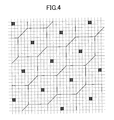
- FIG. 4 is a diagram showing reference non-regular hexagonal cells used in the second embodiment of the halftone screening method.
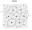
- FIGS. 5A and 5B are diagrams for explaining screen angles in the second embodiment of the halftone screening method.
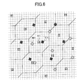
- FIG. 6 is a diagram for explaining center dots of black, cyan and magenta screens in the second embodiment of the halftone screening method.
- a Japanese Laid-Open Patent Application No.7-274015 proposes a digital halftone screening method using square cells, wherein the color irregularities caused by the positioning error of the color screens is suppressed by reproducing the color screens by setting printing angles.
- the printing angle is set to 15 degrees for the cyan screen, 75 degrees for the magenta screen, 0 degree for the yellow screen, and 45 degrees for the black screen.
- the dot image is least conspicuous to the human eyes when the printing angle is 45 degrees, and thus, the printing angle is normally set to 45 degrees for the black screen or, for the magenta screen when placing importance on the reproducibility of skin color.
- the second embodiment of the halftone screening method uses non-regular hexagonal halftone cells, similar to the first embodiment of the halftone screening method.
- the non-regular hexagonal halftone cell is created by cutting a pair of confronting corners of a square halftone cell into a pair of confronting sloping sides. Accordingly, the centers of the non-regular hexagonal halftone cells are arranged in a 45-degree direction (or -45-degree direction), along the sloping sides of the non-regular hexagonal halftone cells, as shown in FIG. 4.
- the black screen (or the magenta screen) is regarded as the reference color screen, and the screens of other colors are rotated by an angle (or turned) and positioned with respect to the reference color screen, as shown in FIGS. 5A and 5B.
- FIG. 5A shows the cyan screen which is rotated relative to the reference black screen
- FIG. 5B shows the magenta screen which is further rotated with respect to the cyan screen relative to the reference black screen.
- the intervals of the black dot K1, the cyan dot C1 and the magenta dot M1 are non-uniform as shown in FIG. 6. Accordingly, even if errors are generated in the dot positions due to mechanical vibration or the like in the color printer, a dot error at one portion will be mutually cancelled by a dot error at another portion. For this reason, the errors in the dot positions do not greatly affect the change in the color tone, and the color irregularities can be suppressed. Since artificial patterns are less conspicuous to the human eyes for the yellow screen, and the positional error of the yellow screen does not greatly affect the change in the color tone, it is possible to uses square yellow cells and a 0 degree printing angle for the yellow screen.
- a second embodiment of the computer-readable storage medium stores a computer program for causing a computer to process image data according to the second embodiment of the halftone screening method.
- the program may be read from a recording medium which forms the computer-readable storage medium and is loaded into the computer or, downloaded from a recording medium of another computer via a communication means such as the Internet.
- the program includes a procedure which causes the computer to rotate color screens relative to a reference color screen.
- This procedure includes the following steps or procedures.
- Step SS1 Using a reference color cell, such as the non-regular hexagonal reference cell, centers of the cells of other colors are arranged at mutually confronting right-angled corners of the reference cell.
- a reference color cell such as the non-regular hexagonal reference cell
- Step SS2 The screens of the other colors are rotated relative to the screen of the reference color. For example, when rotating the color screen, two mutually adjacent color dots which are adjacent to a color dot which becomes the center of rotation of the color screen are selected, and the other color screens are rotated so that the color dot of each of the other color screens becomes arranged between the two mutually adjacent color dots.
- Step SS3 The black or magenta screen may be used as the reference color screen, and the yellow screen may or may not be rotated.
- FIG. 7 is a diagram showing square cells used in the third embodiment of the halftone screening method.
- the cyan square cells are indicated by bold lines in FIG. 7.
- the center magenta dot M1 of the magenta cell of the magenta screen is arranged at one corner of the square cyan cell of the cyan screen.
- the center yellow dot Y1 of the yellow cell of the yellow screen is arranged between the center magenta dots M1 of two mutually adjacent magenta cells.
- the center black dot K1 of the black cell of the black screen is arranged between the center cyan dots C1 of two mutually adjacent cyan cells.
- the embodiments of the halftone screening method and computer-readable storage medium intentionally change the dot position of certain colors within cells of the certain colors relative to the dot position of a reference color within a cell of the reference color, so as to suppress the color tone change and color irregularities caused by positional errors of the color screens. This may be achieved by shifting the cells of the certain colors relative to the cells of the reference color or, by rotating or turning the cells of the certain colors relative to the cells of the reference color.
- FIG. 8 is a flow chart for explaining a fourth embodiment of the halftone screening method according to the present invention.
- the process shown in FIG. 8 corresponds to a process a computer is caused to carry out by a program which is stored in a fourth embodiment of the computer-readable storage medium according to the present invention.
- a step ST1 inputs an 8-bit image data, for example.
- a step ST2 decides whether the input image data, that is, the object, relates to a photograph. If the input image data is characters (document) and the decision result in the step ST2 is NO, a step ST3 carries out the process of the first or third embodiment described above and shifts the positions of the color cells, and carries out a dither process to output a 1-bit image data by applying the scattered dot (dither) image, and the process ends.
- the scattered dot (dither) image the color reproducibility is improved if the overlap of the cells of different colors is small, when taking into consideration the generation of black by overlapping cyan, magenta and yellow.
- a step ST4 carries out the process of the second embodiment described above and rotates or turns the color cells relative to the reference color cells, and carries out a dither process to output a 1-bit image data by applying the clustered dot (dither) image.
- a step ST5 performs a black generation and under color removal (BG/UCR) with respect to the 1-bit image data output by the step ST4, and the process ends.
- BG/UCR black generation and under color removal
- the color reproducibility deteriorates if no screen rotation is made and the screen positions of two colors match.
- the yellow screen does not have a large effect to the human eyes compared to the other colors, and thus, it is possible to simply shift the position of the yellow screen instead of rotating, while the screens of the other colors are rotated relative to the reference color screen.
- FIG. 9 is a diagram for explaining tiles.
- those parts which are the same as those corresponding parts in FIG. 2 are designated by the same reference numerals, and a description thereof will be omitted.
- tiles are used. Each tile is made up of a plurality of cells. In FIG. 9, one tile T is indicated by a bold line.
- the tiles are made up of a collection of cells, so that the halftone becomes continues at the tile boundary, as shown in FIG. 9. If the tiles are arranged to cover the screen (image drawing region) starting from an origin, a coordinate on the screen can be converted into a coordinate within each tile, based on a remainder which is obtained by dividing the image drawing coordinate by the size of the tile. By using such tiles which are known, it becomes unnecessary to carry out an exception process at edges of the screen.
- FIG. 10 is a system block diagram showing a printing system employing the present invention.
- the printing system shown in FIG. 10 includes a personal computer (PC) 101 which functions as a host unit, and a printer 102 which is connected to the personal computer 101 via a host interface (I/F) 103.
- PC personal computer
- I/F host interface
- the personal computer 101 includes a known printer driver 111 which carries out a known region dividing process for dividing image data of an image into image data of each of image regions within the image.
- the printer driver 111 supplies a print command and the image data to the BG/UCR unit 121 within the controller of the printer 102.
- the image data supplied from the printer driver 111 to the BG/UCR unit 121 is an 8-bit RGB data.
- the printer 102 includes a controller 120, a known print engine 130, and a known image processing unit 140.
- the controller 120 controls the print engine 130 to print image data.
- the image processing unit 140 carries out an edge emphasis, a smoothing and the like with respect to the image data to be printed.
- the image processing unit 140 may be provided within the controller 120.
- the controller 120 includes the BG/UCR unit 121, a calibration unit 122, a gamma-correction table 123, a gamma-correction unit 124, a dither data supplying unit 125, a gradation converting unit 126, and a memory 127.
- the BG/UCR unit 121 performs the BG/UCR with respect to the 8-bit RGB (red, green, blue) data received from the printer driver 111, and supplies an 8-bit CMYK (cyan, magenta, yellow, black) data to the gamma-correction unit 124.
- the gamma-correction unit 124 carries out a known gamma-correction based on data received from the gamma-table 123 under control of the calibration unit 122, and supplies an 8-bit gammacorrected CMYK data to the gradation conversion unit 126.
- the gradation conversion unit 126 carries out a gradation conversion based on dither data received from the dither data supplying unit 125, and output a 1-bit CMYK data which is stored in the memory 127.
- the basic structure of the controller 120 is known, except that the dither data supplying unit 125 supplies the dither data which has been subjected to the halftone screening process of the present invention.
- the image processing unit 140 carries out an image processing, such as the edge emphasis and the smoothing, with respect to the 1-bit CMYK data read from the memory 127 and to be printed by the print engine 130.
- the dither data supplying unit 125 is provided within the controller 120, and may be realized by a memory which prestores the dither data which has been subjected to the halftone screening process of the present invention.
- the dither data to be stored in this memory may be calculated by the printing system, such as the personal computer 101 or a processor (not shown) which is provided within the controller 120 or is externally connected to the controller 120.
- the dither data to be stored in this memory may be calculated by the manufacturer of the printing system, and prestored in this memory.
Landscapes
- Engineering & Computer Science (AREA)
- Multimedia (AREA)
- Signal Processing (AREA)
- Facsimile Image Signal Circuits (AREA)
- Color Image Communication Systems (AREA)
- Image Processing (AREA)
- Color, Gradation (AREA)
Applications Claiming Priority (4)
| Application Number | Priority Date | Filing Date | Title |
|---|---|---|---|
| JP2001162682 | 2001-05-30 | ||
| JP2001162682 | 2001-05-30 | ||
| JP2001232336A JP2003051954A (ja) | 2001-05-30 | 2001-07-31 | ハーフトーンスクリーニング方法及びコンピュータプログラム並びに情報記録媒体 |
| JP2001232336 | 2001-07-31 |
Publications (3)
| Publication Number | Publication Date |
|---|---|
| EP1263209A2 true EP1263209A2 (de) | 2002-12-04 |
| EP1263209A3 EP1263209A3 (de) | 2004-11-10 |
| EP1263209B1 EP1263209B1 (de) | 2012-01-11 |
Family
ID=26615983
Family Applications (1)
| Application Number | Title | Priority Date | Filing Date |
|---|---|---|---|
| EP02253822A Expired - Lifetime EP1263209B1 (de) | 2001-05-30 | 2002-05-30 | Halbtonrasterungsverfahren und Speichermedium |
Country Status (3)
| Country | Link |
|---|---|
| US (1) | US7099043B2 (de) |
| EP (1) | EP1263209B1 (de) |
| JP (1) | JP2003051954A (de) |
Cited By (2)
| Publication number | Priority date | Publication date | Assignee | Title |
|---|---|---|---|---|
| WO2005046215A1 (en) * | 2003-11-11 | 2005-05-19 | Eudes Dantas | Tetrastich screening process for cmky printing |
| EP3296117A4 (de) * | 2015-05-15 | 2018-08-15 | FUJIFILM Corporation | Bilderzeugungsverfahren |
Families Citing this family (2)
| Publication number | Priority date | Publication date | Assignee | Title |
|---|---|---|---|---|
| JP3787036B2 (ja) * | 1998-12-28 | 2006-06-21 | 株式会社リコー | スクリーニング方法 |
| JP4311427B2 (ja) * | 2006-09-19 | 2009-08-12 | セイコーエプソン株式会社 | 画像処理回路,階調変換方法及び印刷装置 |
Citations (1)
| Publication number | Priority date | Publication date | Assignee | Title |
|---|---|---|---|---|
| DE3606427A1 (de) | 1985-02-28 | 1986-08-28 | Konishiroku Photo Industry Co. Ltd., Tokio/Tokyo | Bilderzeugungsverfahren und -vorrichtung |
Family Cites Families (3)
| Publication number | Priority date | Publication date | Assignee | Title |
|---|---|---|---|---|
| US4752822A (en) | 1983-03-08 | 1988-06-21 | Canon Kabushiki Kaisha | Color halftone image processing apparatus producing various screen angles and having an adaptive color image data conversion look-up table and a small-capacity masking memory |
| US5394252A (en) | 1994-03-02 | 1995-02-28 | Xerox Corporation | Hybrid quantization method for color document reproduction |
| US6128099A (en) | 1995-06-08 | 2000-10-03 | Delabastita; Paul A. | Halftone screen generator, halftone screen and method for generating same |
-
2001
- 2001-07-31 JP JP2001232336A patent/JP2003051954A/ja active Pending
-
2002
- 2002-05-29 US US10/156,000 patent/US7099043B2/en not_active Expired - Fee Related
- 2002-05-30 EP EP02253822A patent/EP1263209B1/de not_active Expired - Lifetime
Patent Citations (1)
| Publication number | Priority date | Publication date | Assignee | Title |
|---|---|---|---|---|
| DE3606427A1 (de) | 1985-02-28 | 1986-08-28 | Konishiroku Photo Industry Co. Ltd., Tokio/Tokyo | Bilderzeugungsverfahren und -vorrichtung |
Cited By (3)
| Publication number | Priority date | Publication date | Assignee | Title |
|---|---|---|---|---|
| WO2005046215A1 (en) * | 2003-11-11 | 2005-05-19 | Eudes Dantas | Tetrastich screening process for cmky printing |
| EP3296117A4 (de) * | 2015-05-15 | 2018-08-15 | FUJIFILM Corporation | Bilderzeugungsverfahren |
| US10137699B2 (en) | 2015-05-15 | 2018-11-27 | Fujifilm Corporation | Image forming method |
Also Published As
| Publication number | Publication date |
|---|---|
| US20020191203A1 (en) | 2002-12-19 |
| US7099043B2 (en) | 2006-08-29 |
| EP1263209B1 (de) | 2012-01-11 |
| EP1263209A3 (de) | 2004-11-10 |
| JP2003051954A (ja) | 2003-02-21 |
Similar Documents
| Publication | Publication Date | Title |
|---|---|---|
| US8711436B2 (en) | Tint block image generation program and tint block image generation device | |
| JP2002057898A (ja) | グレーレベルハーフトーン処理 | |
| US20100302599A1 (en) | Image processing apparatus, image processing method, and program | |
| US5200832A (en) | Color image recording device with color edit and conversion processing | |
| JP4285127B2 (ja) | 減色処理装置及び減色処理方法 | |
| JPH04336865A (ja) | カラー画像記録装置におけるモノカラー編集方法及び装置 | |
| US7961951B2 (en) | Image processing apparatus capable of accurately removing isolated point noise, image processing method, and computer readable medium | |
| US6795576B2 (en) | Image processing method and apparatus | |
| JP2008005317A (ja) | 画像処理装置及びその方法、並びに、コンピュータプログラムおよび記録媒体 | |
| JP5058299B2 (ja) | 画像処理装置、画像形成装置、画像処理方法、コンピュータプログラム及び記録媒体 | |
| JP4368833B2 (ja) | 画像処理装置、画像処理方法、画像形成装置、プログラム、および記録媒体 | |
| EP0783226A2 (de) | Bildverarbeitungsvorrichtung und -verfahren | |
| EP0949801B1 (de) | Bildverarbeitungsvorrichtung, -verfahren und Speichermedium | |
| EP1263209B1 (de) | Halbtonrasterungsverfahren und Speichermedium | |
| JP2007336549A (ja) | 画像形成装置および画像形成方法 | |
| US7295348B2 (en) | Processor for image processing, method of processing image using the same, and printer incorporating the same | |
| JP2002057913A (ja) | 個人的好みに応じたカラー強調をもたらす像記録装置および像記録方法 | |
| JP3023374B2 (ja) | 複写機の像域別画像処理装置 | |
| US5805295A (en) | Image processing apparatus and method for applying special image effects to output images | |
| US6091520A (en) | Color image forming device | |
| US20070279715A1 (en) | Color conversion definition creating apparatus, and color conversion definition creating program storage medium | |
| JP2013222983A (ja) | 画像処理装置、画像処理方法、コンピュータプログラム | |
| JP3800883B2 (ja) | 画像処理装置および画像処理方法 | |
| JP2010004241A (ja) | 画像処理装置、画像処理プログラム、および画像処理方法 | |
| JPH08275017A (ja) | 画像処理装置及び方法 |
Legal Events
| Date | Code | Title | Description |
|---|---|---|---|
| PUAI | Public reference made under article 153(3) epc to a published international application that has entered the european phase |
Free format text: ORIGINAL CODE: 0009012 |
|
| 17P | Request for examination filed |
Effective date: 20020610 |
|
| AK | Designated contracting states |
Kind code of ref document: A2 Designated state(s): AT BE CH CY DE DK ES FI FR GB GR IE IT LI LU MC NL PT SE TR |
|
| AX | Request for extension of the european patent |
Free format text: AL;LT;LV;MK;RO;SI |
|
| PUAL | Search report despatched |
Free format text: ORIGINAL CODE: 0009013 |
|
| AK | Designated contracting states |
Kind code of ref document: A3 Designated state(s): AT BE CH CY DE DK ES FI FR GB GR IE IT LI LU MC NL PT SE TR |
|
| AX | Request for extension of the european patent |
Extension state: AL LT LV MK RO SI |
|
| AKX | Designation fees paid |
Designated state(s): DE FR GB IT NL |
|
| 17Q | First examination report despatched |
Effective date: 20090508 |
|
| GRAP | Despatch of communication of intention to grant a patent |
Free format text: ORIGINAL CODE: EPIDOSNIGR1 |
|
| GRAS | Grant fee paid |
Free format text: ORIGINAL CODE: EPIDOSNIGR3 |
|
| GRAA | (expected) grant |
Free format text: ORIGINAL CODE: 0009210 |
|
| AK | Designated contracting states |
Kind code of ref document: B1 Designated state(s): DE FR GB IT NL |
|
| REG | Reference to a national code |
Ref country code: GB Ref legal event code: FG4D |
|
| REG | Reference to a national code |
Ref country code: DE Ref legal event code: R096 Ref document number: 60241938 Country of ref document: DE Effective date: 20120308 |
|
| REG | Reference to a national code |
Ref country code: NL Ref legal event code: VDEP Effective date: 20120111 |
|
| PG25 | Lapsed in a contracting state [announced via postgrant information from national office to epo] |
Ref country code: NL Free format text: LAPSE BECAUSE OF FAILURE TO SUBMIT A TRANSLATION OF THE DESCRIPTION OR TO PAY THE FEE WITHIN THE PRESCRIBED TIME-LIMIT Effective date: 20120111 |
|
| PLBE | No opposition filed within time limit |
Free format text: ORIGINAL CODE: 0009261 |
|
| STAA | Information on the status of an ep patent application or granted ep patent |
Free format text: STATUS: NO OPPOSITION FILED WITHIN TIME LIMIT |
|
| PG25 | Lapsed in a contracting state [announced via postgrant information from national office to epo] |
Ref country code: IT Free format text: LAPSE BECAUSE OF FAILURE TO SUBMIT A TRANSLATION OF THE DESCRIPTION OR TO PAY THE FEE WITHIN THE PRESCRIBED TIME-LIMIT Effective date: 20120111 |
|
| 26N | No opposition filed |
Effective date: 20121012 |
|
| REG | Reference to a national code |
Ref country code: DE Ref legal event code: R097 Ref document number: 60241938 Country of ref document: DE Effective date: 20121012 |
|
| PGFP | Annual fee paid to national office [announced via postgrant information from national office to epo] |
Ref country code: GB Payment date: 20140521 Year of fee payment: 13 |
|
| PGFP | Annual fee paid to national office [announced via postgrant information from national office to epo] |
Ref country code: DE Payment date: 20140521 Year of fee payment: 13 Ref country code: FR Payment date: 20140527 Year of fee payment: 13 |
|
| REG | Reference to a national code |
Ref country code: DE Ref legal event code: R119 Ref document number: 60241938 Country of ref document: DE |
|
| GBPC | Gb: european patent ceased through non-payment of renewal fee |
Effective date: 20150530 |
|
| REG | Reference to a national code |
Ref country code: FR Ref legal event code: ST Effective date: 20160129 |
|
| PG25 | Lapsed in a contracting state [announced via postgrant information from national office to epo] |
Ref country code: GB Free format text: LAPSE BECAUSE OF NON-PAYMENT OF DUE FEES Effective date: 20150530 Ref country code: DE Free format text: LAPSE BECAUSE OF NON-PAYMENT OF DUE FEES Effective date: 20151201 |
|
| PG25 | Lapsed in a contracting state [announced via postgrant information from national office to epo] |
Ref country code: FR Free format text: LAPSE BECAUSE OF NON-PAYMENT OF DUE FEES Effective date: 20150601 |