EP1262160A2 - Vorrichtung zur kosmetischen Behandlung mit Ultraschallwellen - Google Patents
Vorrichtung zur kosmetischen Behandlung mit Ultraschallwellen Download PDFInfo
- Publication number
- EP1262160A2 EP1262160A2 EP02011083A EP02011083A EP1262160A2 EP 1262160 A2 EP1262160 A2 EP 1262160A2 EP 02011083 A EP02011083 A EP 02011083A EP 02011083 A EP02011083 A EP 02011083A EP 1262160 A2 EP1262160 A2 EP 1262160A2
- Authority
- EP
- European Patent Office
- Prior art keywords
- ultrasonic wave
- drive
- frequency
- cosmetic device
- drive unit
- Prior art date
- Legal status (The legal status is an assumption and is not a legal conclusion. Google has not performed a legal analysis and makes no representation as to the accuracy of the status listed.)
- Withdrawn
Links
- 239000002537 cosmetic Substances 0.000 title claims abstract description 110
- 230000001902 propagating effect Effects 0.000 claims abstract description 22
- 239000000523 sample Substances 0.000 claims abstract description 19
- 230000000638 stimulation Effects 0.000 claims abstract description 5
- 230000001815 facial effect Effects 0.000 abstract description 5
- 238000010586 diagram Methods 0.000 description 48
- 238000000034 method Methods 0.000 description 17
- 230000000694 effects Effects 0.000 description 16
- 230000010355 oscillation Effects 0.000 description 14
- 230000008859 change Effects 0.000 description 9
- 238000004519 manufacturing process Methods 0.000 description 6
- 230000001052 transient effect Effects 0.000 description 6
- 230000003247 decreasing effect Effects 0.000 description 4
- 238000006073 displacement reaction Methods 0.000 description 3
- XAGFODPZIPBFFR-UHFFFAOYSA-N aluminium Chemical compound [Al] XAGFODPZIPBFFR-UHFFFAOYSA-N 0.000 description 2
- 229910052782 aluminium Inorganic materials 0.000 description 2
- 239000000919 ceramic Substances 0.000 description 2
- 238000010438 heat treatment Methods 0.000 description 2
- 230000004044 response Effects 0.000 description 2
- 238000001228 spectrum Methods 0.000 description 2
- 230000002411 adverse Effects 0.000 description 1
- 230000020169 heat generation Effects 0.000 description 1
- 230000006872 improvement Effects 0.000 description 1
- 230000004048 modification Effects 0.000 description 1
- 238000012986 modification Methods 0.000 description 1
- 230000008569 process Effects 0.000 description 1
- 230000009467 reduction Effects 0.000 description 1
Images


Classifications
-
- A—HUMAN NECESSITIES
- A61—MEDICAL OR VETERINARY SCIENCE; HYGIENE
- A61H—PHYSICAL THERAPY APPARATUS, e.g. DEVICES FOR LOCATING OR STIMULATING REFLEX POINTS IN THE BODY; ARTIFICIAL RESPIRATION; MASSAGE; BATHING DEVICES FOR SPECIAL THERAPEUTIC OR HYGIENIC PURPOSES OR SPECIFIC PARTS OF THE BODY
- A61H23/00—Percussion or vibration massage, e.g. using supersonic vibration; Suction-vibration massage; Massage with moving diaphragms
- A61H23/02—Percussion or vibration massage, e.g. using supersonic vibration; Suction-vibration massage; Massage with moving diaphragms with electric or magnetic drive
- A61H23/0245—Percussion or vibration massage, e.g. using supersonic vibration; Suction-vibration massage; Massage with moving diaphragms with electric or magnetic drive with ultrasonic transducers, e.g. piezoelectric
-
- A—HUMAN NECESSITIES
- A61—MEDICAL OR VETERINARY SCIENCE; HYGIENE
- A61H—PHYSICAL THERAPY APPARATUS, e.g. DEVICES FOR LOCATING OR STIMULATING REFLEX POINTS IN THE BODY; ARTIFICIAL RESPIRATION; MASSAGE; BATHING DEVICES FOR SPECIAL THERAPEUTIC OR HYGIENIC PURPOSES OR SPECIFIC PARTS OF THE BODY
- A61H23/00—Percussion or vibration massage, e.g. using supersonic vibration; Suction-vibration massage; Massage with moving diaphragms
- A61H23/02—Percussion or vibration massage, e.g. using supersonic vibration; Suction-vibration massage; Massage with moving diaphragms with electric or magnetic drive
-
- A—HUMAN NECESSITIES
- A61—MEDICAL OR VETERINARY SCIENCE; HYGIENE
- A61N—ELECTROTHERAPY; MAGNETOTHERAPY; RADIATION THERAPY; ULTRASOUND THERAPY
- A61N7/00—Ultrasound therapy
- A61N2007/0073—Ultrasound therapy using multiple frequencies
Definitions
- the present invention relates to an ultrasonic wave cosmetic device for producing ultrasonic wave stimulation on the facial skin by a vibration unit having an ultrasonic wave vibration element.
- ultrasonic wave cosmetic devices have been used for providing ultrasonic wave vibrations (ultrasonic wave stimulation) to the facial skin by contacting the facial skin with a vibration unit established at a probe head and configured by an ultrasonic wave vibration element and a horn.
- Figure 22 is a diagram showing an example of a conventional structure of such an ultrasonic wave cosmetic device.
- Figure 22A shows an entire structure of the device, and
- Figure 22B shows an enlarged view of a vibration unit 10 descried later.
- the ultrasonic wave cosmetic device is comprised of an ultrasonic wave vibration element 1 with a thickness of TH1 for generating ultrasonic waves, a probe 3 having the vibration unit 10 where one surface of the vibration unit contacts with the skin while the other surface is provided with a horn 2 of a thickness TH2 connected to the ultrasonic wave vibration element 1, and a drive unit 4 for driving the ultrasonic wave vibration element 1.
- the ultrasonic wave vibration element 1 is made of piezoelectric ceramic, and horn 2 is made of aluminum.
- FIG 23 is a diagram showing the ultrasonic wave (standing wave) propagating through the vibration unit 10 in the conventional ultrasonic wave cosmetic device.
- the longitudinal ultrasonic wave is illustrated as a transversal wave.
- the wavelength ⁇ of the ultrasonic wave is unchanged by the difference of medium.
- the cross section of the vibration unit 10 is shown on the right, and the waveforms of the ultrasonic wave in the vibration unit 10 is shown on the left.
- the thickness TH1 of the ultrasonic wave vibration element 1 and the thickness TH2 of the horn 2 are set to a half-wave length ⁇ /2 and an integer multiple of the half-wave length ⁇ /2 (two times, in this case), respectively.
- an ultrasonic wave with a frequency of 1-3MHz is used in the ultrasonic wave cosmetic device.
- the thickness TH1 of the ultrasonic wave vibration element 1 and the thickness TH2 of the horn 2 are respectively, for example, 2mm and 4mm, when the frequency is 1MHz, and 0.7mm and 1.4mm, when the frequency is 3MHz.
- the thickness TH1 of ultrasonic wave vibration element 1 and the thickness TH2 of the horn 2 need to be thinner as the frequency of the ultrasonic wave increases.
- a thinner ultrasonic wave vibration element 1, for example, less than 0.6mm and a thinner horn 2, for example, less than 1mm tend to cause variations in their performances. Further, the performance may change significantly due to, for example, damages resulted from stress caused by the vibrations during use, thus, making it difficult to achieve the desired performance. As a result, a high frequency ultrasonic wave cosmetic device is difficult to achieve in the conventional technology.
- the vibration unit 10 has to be replaced when using an ultrasonic wave of different frequency, which requires a plurality of vibration units 10 and thus involves a complicated exchange process.
- This invention has been made in view of the above noted problems involved in the conventional technology, and it is an object of the present invention to provide an ultrasonic wave cosmetic device which is capable of using ultrasonic waves with high frequencies.
- the ultrasonic wave cosmetic device for providing ultrasonic stimulation to skin is comprised of an ultrasonic wave vibration element for generating ultrasonic waves, a probe provided with a vibration unit where one surface of the vibration unit contacts the skin and another surface is formed of a horn connected to the ultrasonic wave vibration element, and a drive unit for driving the ultrasonic wave vibration element.
- the drive unit produces one of a first fundamental frequency where a half-wave length thereof matches a thickness of the vibration unit when propagating therethrough, and a first harmonic frequency which is an integer multiple of the first fundamental frequency, as a drive frequency for driving the ultrasonic wave vibration element.
- the drive unit since the drive unit produces at least one of the first fundamental frequency and the first harmonic frequency as the drive frequency, it is possible to drive the vibration unit with high frequency as well as with a plurality of frequencies.
- the drive unit produces one of a second fundamental frequency, where a half-wave length thereof matches a thickness of the ultrasonic wave vibration element when propagating therethrough, and a second harmonic frequency which is an integer multiple of the second fundamental frequency, as the drive frequency.
- the drive unit produces at least one of the second fundamental frequency or the second harmonic frequency as the drive frequency
- the drive unit produces at least one of the second fundamental frequency and a third harmonic frequency which is an odd multiple of the second fundamental frequency, as the drive frequency.
- the second fundamental frequency or the third harmonic frequency is used as the drive frequency, the displacement of the ultrasonic wave vibration element between the surface facing the horn and the other surface will be in the opposite directions. Due to this, the ultrasonic wave vibration element will mechanically resonate, further improving the drive efficiency.
- the drive unit produces one of the third harmonic frequency as the drive frequency. According to this structure, since one of the third harmonic frequencies is used as the drive frequency, the structure of the drive unit is simplified, thereby achieving small size and low cost.
- the drive unit includes a separately excited oscillator for determining the drive frequency.
- the oscillation frequency (drive frequency) becomes adjustable. Due to this, the desired characteristics can be achieved by the adjustment during the production of the ultrasonic wave vibration element and the horn even when the characteristics thereof vary.
- the drive unit includes a self-excited oscillator for determining the drive frequency. According to this structure, since the self-excited oscillator is used, the drive unit with improved drive efficiency can be achieved.
- the drive unit produces a plurality of frequencies of the second fundamental frequency and the third harmonic frequency as the drive frequencies, and has a frequency controller for switching between the plurality of drive frequencies.
- the frequency controller for switching between the plurality of drive frequencies.
- the drive unit includes a separately excited oscillator for determining the drive frequency
- the oscillation frequency (drive frequency) becomes adjustable. Due to this, the desired characteristics can be achieved by the adjustment during the production of the ultrasonic wave vibration element and the horn even when the characteristics thereof vary.
- the drive unit includes a self-induced oscillator for determining the drive frequency. According to this structure, since the self-excited oscillator is used, the drive unit with improved drive efficiency can be achieved.
- the drive unit includes a power controller for controlling a drive power of each of the plurality of drive frequencies.
- the power selector since the power selector is provided, the output of the ultrasonic wave can be adjusted for each drive frequency. Further, since the transient stress applied to the joint surface between the ultrasonic wave vibration element and the horn generated right after switching the drive frequency can be reduced by decreasing the drive power during the switching, the effect of the stress (e.g., breakage of the joint surface) can be reduced.
- the drive unit includes a condition selector for selecting an switching order of the plurality of drive frequencies and a drive time of each of the drive frequencies.
- the frequency controller switches the drive frequencies under control of the condition selector.
- the drive unit includes a time selector for selecting a stop time during which a drive power of the drive frequency is stopped when the drive frequencies are switched.
- the frequency controller switches the drive frequencies under the control of the condition selector and the time selector.
- the drive unit includes a frequency mixer for mixing a plurality of drive frequencies selected from the second fundamental frequency and the third harmonic frequency and for producing a frequency mixed wave which is used as the drive frequency.
- the mixed frequency wave is generated by mixing the second fundamental frequency and the third harmonic frequency by the frequency mixer and the drive unit drives the vibration unit by the mixed frequency wave, the effects based on the plurality of frequencies can be achieved at the same time.
- the drive unit includes output power adjustment means for adjusting an output power of each of the drive frequencies. According to this structure, the output power of the ultrasonic wave can be adjusted for each of the drive frequencies.
- the vibration unit is comprised of an ultrasonic wave vibration and a horn. According to this structure, since the vibration unit is structured with one ultrasonic wave vibration element and one horn, it becomes simple and low cost.
- the vibration unit is comprised of a plurality of ultrasonic wave vibration elements and a horn. According to the above structure, since the vibration unit is structured with several ultrasonic wave vibration elements and one horn, the number of frequencies proportional to the number of ultrasonic wave vibration elements can be used, and thus, various methods of use can be applied.
- the drive unit drives each of the plurality of ultrasonic wave vibration elements separately. According to this structure, since the drive unit drives each of the several ultrasonic wave vibration elements, the number of frequencies proportional to the number of ultrasonic wave vibration elements can be used, and thus, various methods of use can be applied.
- the drive unit drives the plurality of ultrasonic wave vibration elements at the same time. According to this structure, since the drive unit drives the several ultrasonic wave vibration elements at the same time, the effects based on the number of frequencies proportional to the number of ultrasonic wave vibration elements can be achieved at the same time.
- the drive unit drives the plurality of ultrasonic wave vibration elements while sequentially switching them. According to this structure, since the drive unit sequentially switches and drives the several ultrasonic wave vibration elements, the number of frequencies proportional to the number of ultrasonic wave vibration elements can be used, and thus, various methods of use can be applied.
- Figure 1 is a diagram showing the condition of the ultrasonic wave (standing wave) propagating through the vibration unit of the ultrasonic wave cosmetic device in the first embodiment of the present invention.
- Figure 2 a diagram showing the condition of the ultrasonic wave (standing wave) propagating through the vibration unit of the ultrasonic wave cosmetic device in the second embodiment of the present invention.
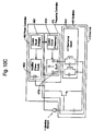
- Figure 3 is a schematic block diagram showing the structure of the ultrasonic wave cosmetic device in the fourth embodiment of the present invention.
- Figure 4 is a schematic block diagram showing the structure of the ultrasonic wave cosmetic device in the fifth embodiment of the present invention.
- Figure 5 is a block diagram showing the structure of the ultrasonic wave cosmetic device related in the sixth embodiment of the present invention.
- Figure 6 is schematic block diagram showing the structure of the ultrasonic wave cosmetic device in the seventh embodiment of the present invention.
- Figure 7 is a schematic block diagram showing the structure of the ultrasonic wave cosmetic device in the eighth embodiment of the present invention.
- Figures 8A-8C are waveform diagrams showing the operation of the ultrasonic wave cosmetic device in the eighth embodiment of the present invention.
- Figure 9 is a block diagram showing the structure of the ultrasonic wave cosmetic device in the ninth embodiment of the present invention.
- Figures 10A-10C are schematic block diagrams showing the structure of the ultrasonic wave cosmetic device in the tenth embodiment of the present invention.
- Figures 11A-11D are waveform diagrams showing the operation of the ultrasonic wave cosmetic device in the tenth embodiment of the present invention.
- Figure 12 is a schematic block diagram showing the structure of the ultrasonic wave cosmetic device in the eleventh embodiment of the present invention.
- Figure 13 is a waveform diagram showing the operation of the ultrasonic wave cosmetic device in the eleventh embodiment of the present invention.
- Figure 14 is a block diagram showing the structure of the ultrasonic wave cosmetic device in the twelfth embodiment of the present invention.
- Figure 15 is a waveform diagram showing the operation of the ultrasonic wave cosmetic device in the twelfth embodiment of the present invention.
- Figure 16 is a schematic block diagram showing the structure of the ultrasonic wave cosmetic device in the thirteenth embodiment of the present invention.
- Figures 17A-17C are waveform diagrams showing the operation of the ultrasonic wave cosmetic device in the thirteenth embodiment of the present invention.
- Figure 18 is a block diagram showing the structure of the ultrasonic wave cosmetic device in the fourteenth embodiment of the present invention.
- Figures 19A and 19B are schematic block diagrams showing the structure of the ultrasonic wave cosmetic device in the fifteenth embodiment of the present invention.
- Figures 20A-20C are graphs describing the operation of the filter circuit used in the fifteenth embodiment of the present invention.
- Figures 21A-21D are cross sectional views of the vibration unit of the ultrasonic wave cosmetic device in the sixteenth embodiment of the present invention.
- Figure 22A is a schematic diagram and Figure 22B is a cross sectional view respectively showing the structure of the conventional ultrasonic wave cosmetic device.
- Figure 23 is a diagram showing the condition of the ultrasonic wave (standing wave) propagating through the vibration unit in the conventional ultrasonic wave cosmetic device.
- the structure of the ultrasonic wave cosmetic device related to the first embodiment of the present invention is the same as the conventional structure shown in Figure 22, although a drive signal (ultrasonic wave) is different.
- the ultrasonic wave cosmetic device is comprised of an ultrasonic wave vibration element 1 with a thickness of TH1 for generating ultrasonic waves, a probe 3 having a vibration unit 10, and a drive unit 4 for driving the ultrasonic wave vibration element 1.
- the vibration unit 10 has one surface which comes in contact with the facial skin and another surface which is structured by a horn 2 with a thickness of TH2 connected to the ultrasonic wave vibration element 1.
- the drive unit 4 can be installed inside the probe 3.
- the ultrasonic wave vibration element 1 is made of, for example, piezoelectric ceramic, and the horn 2 is made of, for example, aluminum.
- a cross section of the vibration unit 10 is shown on the right side.
- the waveforms of the ultrasonic wave in the vibration unit 10 are shown in the order of drive frequency from the left toward the right.
- the drive frequencies are in the order of a first fundamental frequency FR1 where a half-wave length ⁇ /2 of the ultrasonic wave propagating through the vibration unit 10 substantially matches the thickness of vibration unit 10 (TH1 + TH2), a second harmonic frequency which is twice the first fundamental frequency (2 x FR1), a third harmonic frequency which is three times the first fundamental frequency (3 x FR1), a fourth harmonic frequency which is four times the first fundamental frequency (4 x FR1), and a fifth harmonic frequency five times the first fundamental frequency (5 x FR1) from the left to right.
- the first fundamental frequency FR1 will be 0.8MHz
- the second harmonic frequency will be 1.6MHz
- the third harmonic frequency will be 2.4MHz
- the fourth harmonic frequency will be 3.2MHz
- the fifth harmonic frequency will be 4.0MHz, respectively. Consequently, in this invention, it has become possible to drive the vibration element 1 at a high frequency (4.0MHz) as well as with a plurality of frequencies (5 different frequencies in this case).
- the structure of the ultrasonic wave cosmetic device related to the second embodiment of the present invention has the same structure as in the first embodiment, although a drive signal (ultrasonic wave) is different.
- a cross section of the vibration unit 10 is shown on the right side.
- the waveforms of the ultrasonic wave in the vibration unit 10 are shown in the order of drive frequency from the left toward the right.
- the drive frequencies are in the order of a second fundamental frequency FR2 where a half-wave length ⁇ /2 of the ultrasonic wave propagating through the vibration unit 10 substantially matches the thickness TH1 of the vibration element 1, a second harmonic frequency which is twice the second fundamental frequency (2 x FR2), a third harmonic frequency which is three times the second fundamental frequency (3 x FR2), a fourth harmonic frequency which is four times the second fundamental frequency (4 x FR2), and a fifth harmonic frequency five times the second fundamental frequency (5 x FR2) from the left to right.
- the structure of the ultrasonic wave cosmetic device related to the third embodiment of the present invention has the same structure as in the first embodiment.
- the condition of the ultrasonic waves (standing waves) propagating through the vibration unit 10 of the ultrasonic wave cosmetic device related to the third embodiment of the present invention is, for example, the waveforms of the ultrasonic waves of vibration unit 10 when the second fundamental frequency FR2 and third harmonic frequency which is three times the second fundamental frequency (3 x FR2) of Figure 2 are used as drive frequencies.
- the displacement of the ultrasonic wave vibration element 1 between the surface facing the horn 2 and the other surface will be in the opposite directions. Due to this, the ultrasonic wave vibration element 1 mechanically resonates at the drive frequency, resulting in further improvement of the drive efficiency.
- FIG. 3 is a diagram showing the structure of the ultrasonic wave cosmetic device related to the fourth embodiment of the present invention.
- the probe 3 has the same structure as that in the first embodiment.
- the drive unit 4 is comprised of an oscillator 41 for determining the drive frequency and an amplifier 42 for amplifying the signal from the oscillator 41. In other words, the drive unit 4 drives the vibration unit 10 by a single drive frequency.
- the condition of the ultrasonic waves (standing waves) propagating through the vibration unit 10 of the ultrasonic wave cosmetic device related to the fourth embodiment of the present invention is, for example, the waveforms of the ultrasonic waves of vibration unit 10 when only the third harmonic frequency (3 x FR2) of Figure 2 is used as the drive frequency. Since the drive unit 4 is to drive only one drive frequency, the structure of drive unit 4 is simplified, allowing the reduction in size and cost.
- FIG. 4 is a diagram showing the structure of the ultrasonic wave cosmetic device related to the fifth embodiment of the present invention.
- the probe 3 has the same structure as that in the first embodiment.
- the drive unit 4 is comprised of a separately excited oscillator 411 for determining the drive frequency and an amplifier 421 for amplifying the signal from the separately excited oscillator 411.
- drive element 4 drives the vibration unit 10 by a single drive frequency.
- the separately excited oscillator 411 is structured with, for example, a PLL (phase-locked loop) circuit.
- the PLL circuit is a well known structure provided with, for example, a programmable frequency divider, a phase comparator, a VCO (voltage controlled oscillator), and a low-pass filter. A voltage supplied from the phase comparator is converted into a DC signal by the low-pass filter and is applied to the VCO to adjust the oscillation frequency.
- the drive unit 4 is comprised of the separately excited oscillator 411, the oscillation frequency (drive frequency) is adjustable. Thus, during the production of ultrasonic wave vibration element 1 and the horn 2, the desired characteristics can be achieved by such adjustments even when their characteristics vary.
- FIG. 5 is a diagram showing the structure of the ultrasonic wave cosmetic device related to the sixth embodiment of the present invention.
- the probe 3 has the same structure as that in the first embodiment.
- the drive unit is comprised of a self-excited oscillator 412 for determining the drive frequency and an amplifier 422 for amplifying the signal from the self-excited oscillator 412.
- drive element 4 drives the vibration unit 10 by a single drive frequency.
- the self-excited oscillator 412 is structured with, for example, a Colpitts oscillation circuit. As known in the art, a Colpitts oscillation circuit is provided with an LC resonance circuit 4121 as a feedback circuit. Since the drive unit 4 has the self-excited oscillator 412, which is able to determine its oscillation frequency, the drive unit 4 is able to achieve a high drive efficiency.
- FIG. 6 is a block diagram showing the structure of the ultrasonic wave cosmetic device related to the seventh embodiment of the present invention.
- the probe 3 has the same structure as that in the first embodiment.
- the drive unit 4 is comprised of an oscillator 44 for determining the drive frequency, an amplifier 42 for amplifying the drive signal from the oscillator 44, and a frequency controller 43 for controlling the drive frequency from the oscillator 44. Since the drive unit 4 includes the frequency controller 43, it can easily drive the vibration unit 10 with several different frequencies.
- the frequency controller 43 changes the drive frequency upon receiving the instruction by a user of the ultrasonic wave cosmetic device. Alternatively, by setting the change conditions such as an switching order of several frequencies and each drive time length in advance, the frequency controller 43 changes the drive frequency based on such conditions.
- FIG. 7 is a block diagram showing the structure of the ultrasonic wave cosmetic device related to the eighth embodiment of the present invention.
- the probe 3 has the same structure as that in the first embodiment.
- the drive unit 4 is comprised of a separately excited oscillator 441 for determining the drive frequency, an amplifier 421 for amplifying the signals from the separately excited oscillator 441, and a frequency controller 431 for controlling the drive frequency from the separately excited oscillator 441.
- the separately excited oscillator 441 is structured with, for example, a PLL circuit.
- the frequency controller 431 is comprised of a switch 4311 for producing a frequency switch signal upon the operation by the user of the ultrasonic wave cosmetic device, and a control circuit 4312 for changing the oscillation frequency of the separately excited oscillator 441 based on the switch signal from the switch 4311.
- Figures 8A-8C are waveform diagrams for explaining an operational procedure of the ultrasonic wave cosmetic device related to the eighth embodiment of the present invention.
- the horizontal axis represents time
- the vertical axis represents a signal level at an output of the switch 4311 in Figure 8A, a signal level at an output of the control circuit 4312 in Figure 8B, and a signal level of an output of the separately excited oscillator 441 in Figure 8C.
- the operation is explained for the case where the second fundamental frequency FR2 and the third harmonic frequency which is three times the second fundamental frequency (3 x FR2) as shown in Figure 2 are switched with each other as the drive frequency.
- the second fundamental frequency FR2 is selected.
- the output of the switch 4311 is changed from the second fundamental frequency FR2 to the third harmonic frequency (3 x FR2) upon receiving the instruction by the user of the ultrasonic wave cosmetic device.
- a control signal is supplied from the control circuit 4312 to the oscillator 441.
- the drive frequency from the separately excited oscillator 441 is switched from the second fundamental frequency FR2 to the third harmonic frequency (3 x FR2).
- the drive unit 4 includes the frequency controller 431, the drive frequency can be switched in response to the operation by the user of the ultrasonic wave cosmetic device. Further, since the drive unit 4 includes the separately excited oscillator 441, it is possible to adjust the oscillation frequency (drive frequency). Thus, during the production of the ultrasonic wave vibration element 1 and the horn 2, the desired characteristics can be achieved by this frequency adjustment even when the characteristics of these components vary.
- FIG 9 is a diagram showing the structure of the ultrasonic wave cosmetic device related to the ninth embodiment of the present invention.
- the probe 3 has the same structure as that in the first embodiment.
- the drive unit 4 is comprised of a self-excited oscillator 443 for determining the drive frequency, an amplifier 422 for amplifying the drive signal from the self-excited oscillator 443, and a frequency controller 432 for controlling the drive frequency from the self-excited oscillator 443.
- the self-excited oscillator 443 is comprised of an LC resonance circuit 4431, which is capable of generating two different resonance frequencies (such as the second fundamental frequency FR2 and the third harmonic frequency (3 x FR2) in Figure 2).
- the frequency controller 432 is comprised of a switch 4321 for producing a frequency switch signal upon the operation by the user of the ultrasonic wave cosmetic device, an internal switch 4323 for switching the LC resonance circuit 4431 of the self-excited oscillator 443, and a control circuit 4322 for providing a control signal based to the internal switch 4323 based on the frequency switch signal from the switch 4321.
- the frequency switch signal is generated. Based on this frequency switch signal, a control signal is generated by the control circuit 4322. Further, based on this control signal, the LC resonance circuit 4431 of the self-excited oscillator 443 is switched by the internal switch 4323, thereby changing the drive frequency.
- the drive unit 4 is comprised of the frequency controller 432, the drive frequency can be switched in response to the operation by the user of the ultrasonic wave cosmetic device. Further, since the drive unit 4 is also comprised of the self-excited oscillator 443, the drive unit 4 with a high drive efficiency can be achieved.
- FIG 10A is a diagram showing the structure of the ultrasonic wave cosmetic device related to the tenth embodiment of the present invention.
- the probe 3 has the same structure as that in the first embodiment.
- the drive unit 4 is comprised of an oscillator 44 for determining the drive frequency, an amplifier 45 for amplifying the drive signal from the oscillator 44, a frequency controller 47 for controlling the drive frequency from the oscillator 44, and a power controller 46 for setting a drive power level for each drive frequency.
- the frequency controller 47 also supplies a control signal to the power controller 46.
- the power controller 46 sets the drive power level per every drive frequency based on the control information (information relating to the change in the drive frequency) from the frequency controller 47.
- Figure 10B shows an example of the ultrasonic wave cosmetic device related to the tenth embodiment of the present invention when the oscillator is a separately excited oscillator.
- Figure 10C shows an example of the ultrasonic wave cosmetic device related to the tenth embodiment of the present invention when the oscillator is a self-excited oscillator.
- Figures 11A-11D are waveform diagrams for explaining the operational procedure of the ultrasonic wave cosmetic device related to the tenth embodiment of the present invention.
- the horizontal axis represents time
- the vertical axis represents an output of the frequency controller 47 in Figure 11A, an output of the power controller 46 in Figure 11B, an output of the oscillator 44 in Figure 11C, and an output of the amplifier 45 in Figure 11D.
- the operation is explained for the case where the second fundamental frequency FR2 and the third harmonic frequency which is three times the second fundamental frequency (3 x FR2) as shown in Figure 2 are switched with each other as the drive frequency.
- the second fundamental frequency FR2 is selected.
- the output of the frequency controller 47 is changed from the second fundamental frequency FR2 to the third harmonic frequency (3 x FR2) upon receiving the operation by the user of the ultrasonic wave cosmetic device.
- a control signal is supplied to the power controller 46.
- the drive frequency is switched from the second fundamental frequency FR2 to the third harmonic frequency (3 x FR2) by the oscillator 44, and the drive power is changed by the amplifier 45.
- drive unit 4 includes the power controller 46, the output of the ultrasonic wave of each drive frequency can be controlled. Further, by decreasing the drive power during switching the drive frequencies, transient stress at the joint surface between the ultrasonic wave vibration element 1 and the horn 2 produced right after the frequency switching can be reduced, thereby decreasing adverse effects (i.e., breakage of joint surface) of the stress.
- FIG 12 is a diagram showing the structure of the ultrasonic wave cosmetic device related to the eleventh embodiment of the present invention.
- the structure of the probe 3 is the same as that in the first embodiment.
- the drive unit 4 is comprised of an oscillator 44 for determining the drive frequency, an amplifier 45 for amplifying the drive signal from the oscillator 44, a frequency controller 48 for controlling the frequency of the oscillator 44, a power controller 46 for controlling the drive power for each drive frequency, and a condition selector 491 for selecting the conditions to change the drive frequency.
- the frequency controller 48 also supplies a control signal to the power controller 46.
- the condition selector 491 sets a switching order of the plurality of drive frequencies and a drive time per each of the drive frequencies.
- the frequency controller 48 changes the oscillation frequency of the oscillator 44 based on these conditions.
- explanation will be mode for the case where the change in the drive power of each drive frequency in the amplifier 45 is not conducted but only the drive frequency has to be changed.
- Figure 13 is a waveform diagram for explaining the operational procedure of the ultrasonic wave cosmetic device related to the eleventh embodiment of the present invention.
- the horizontal axis represents the time
- the vertical axis represents the output of the oscillator 44.
- the case where the second fundamental frequency FR2 and the third harmonic frequency which is three times the second fundamental frequency (3 x FR2) shown in Figure 2, as well as the fifth harmonic frequency which is five times the second fundamental frequency (5 x FR2) not shown in Figure 2 are switched with one another as the drive frequencies will be explained.
- condition selector 491 instructions, for example, by a user of the ultrasonic wave cosmetic device user is received. It is also assumed that the switching order of the drive frequencies is set in the order of second fundamental frequency, third harmonic frequency, and fifth harmonic frequency. The values of drive times TL1, TL2, and TL3 for the corresponding drive frequencies are also set.
- the switching order of the drive frequency and the drive time per drive frequency is supplied to the frequency controller 48.
- the frequency controller 48 the drive frequencies from the oscillator 44 are changed based on this information.
- the second fundamental frequency FR2 is oscillated during the drive time TL1
- the third harmonic frequency is oscillated during the drive time TL2
- the fifth harmonic frequency is oscillated during the drive time TL3. The above procedure is repeated thereafter.
- the drive unit 4 includes the condition selector 491 and switches the drive frequencies by the frequency controller 48 under the conditions specified in the condition selector 491, the plurality of drive frequencies can be used under desired conditions.
- FIG 14 is a diagram showing the structure of the ultrasonic wave cosmetic device related to the twelfth embodiment of the present invention.
- the structure of the probe 3 is the same as that in the first embodiment.
- the drive unit 4 is comprised of an oscillator 44 for determining the drive frequency, an amplifier 45 for amplifying the drive signal from the oscillator 44, a frequency controller 481 for controlling the drive frequency from the oscillator 44, a power controller 46 for controlling the drive power for each drive frequency, a condition selector 491 for selecting the conditions for changing the drive frequency, and a time selector 492 for selecting a time to stop the drive power.
- the frequency controller 481 also supplies a control signal to the power controller 46.
- the condition selector 491 sets and selects a switching order of a plurality of drive frequencies and a drive time for each drive frequency.
- the time selector 492 sets and selects the time to stop the drive power during the switching between the drive frequencies.
- the frequency controller 481 controls the drive frequency from the oscillator 44 based on the conditions set in the condition selector 491 and the time selector 492. Here, explanation will be made for the case where the drive power per drive frequency by the amplifier 45 is not changed but only the drive frequency is changed.
- Figure 15 is a waveform diagram for explaining the operational procedure of the ultrasonic wave cosmetic device related to the twelfth embodiment of the present invention.
- the horizontal axis represents the time
- the vertical axis indicates the output of oscillator 44.
- the case where the second fundamental frequency FR2 and the third harmonic frequency which is three times the second fundamental frequency (3 x FR2) shown in Figure 2, as well as the fifth harmonic frequency which is five times the second fundamental frequency (5 x FR2) not shown in Figure 2 are switched with one another as the drive frequencies will be explained.
- condition selector 491 instructions by, for example, a user of the ultrasonic wave cosmetic device user is received and that the switching order of the drive frequencies is set in the order of second fundamental frequency, third harmonic frequency, and fifth harmonic frequency. It is also assumed that the values of drive times TL1, TL2, and TL3 for the corresponding drive frequencies are set. Further, by the time selector 492, a stop time TL0 is pre-set in memory means.
- the switching order of the drive frequency and the drive time for each drive frequency is supplied to the frequency controller 481 by the condition selector 491.
- the stop time TL0 is supplied by the time selector 492, and based on this information, the drive frequency from the oscillator 44 is changed by the frequency controller 481.
- the oscillator 44 is oscillated at the second fundamental frequency FR2 during the drive time TL1, then stopped during the stop time TL0.
- the oscillator 44 is oscillated at the third harmonic frequency (3 x FR2) during the drive time TL2, then stopped during the stop time TL0.
- the oscillator 44 is oscillated at the fifth harmonic frequency (5 x FR2) during the drive time TL3, then stopped during the stop time TL0.
- the above procedure is repeated thereafter.
- the drive unit 4 includes the time selector 492 for setting the time for stopping the drive power and switches the drive frequency by the frequency controller during the stop time conditions set in the time selector 492, the transient stress acted on the joint surface between the ultrasonic wave vibration element 1 and the horn 2 immediately after the drive frequencies are switched can be reduced. Hence, the effects of the stress (e.g., the breakage of the joint surface) can be reduced and heat generation on the surface of the horn 2 can also be prevented.
- the stress e.g., the breakage of the joint surface
- FIG 16 is a block diagram showing the structure of the ultrasonic wave cosmetic device related to the thirteenth embodiment of the present invention.
- the structure of probe 3 is the same as that shown in the first embodiment.
- the drive unit 4 is comprised of oscillators 444 and 445 for determining the drive frequencies, a frequency mixer 5 for mixing the drive signals from the oscillators 444 and 445, and an amplifier 42 for amplifying the drive signals combined by the mixer 5.
- Figures 17A-17C are waveform diagrams for explaining the operational procedure of the ultrasonic wave cosmetic device related to the thirteenth embodiment of the present invention.
- the horizontal axis represents the time
- the vertical axis represents an output of the oscillator 444 in Figure 17A, an output of the oscillator 445 in Figure 17B, and an output of the amplifier 42 (or mixer 5) in Figure 17C.
- the oscillation frequency of the oscillator 444 is the second fundamental frequency FR2 of Figure 2
- the oscillation frequency of the oscillator 445 is the third harmonic frequency (3 x FR2) of Figure 2.
- the outputs of the oscillators 444 and 445 are mixed with each other by the frequency mixer 5 to obtain a frequency combined wave, where the frequency combined wave is then amplified by the amplifier 42. Since the drive unit 4 drives the vibration unit 10 by the use of that frequency mixed wave, the effects based on the plurality of frequencies can be achieved at the same time.
- FIG 18 is a diagram showing the structure of the ultrasonic wave cosmetic device related to the fourteenth embodiment of the present invention.
- the structure of the probe 3 is the same as that shown in the first embodiment.
- the drive unit 4 is comprised of oscillators 444 and 445 for determining the drive frequencies, amplifiers 453 and 454 for amplifying the drive signals from the oscillators 444 and 445, variable voltage power supplies 61 and 62 for controlling a power output of each of the amplifiers 453 and 454, and a frequency mixer 51 for mixing the frequency of the drive signals from the amplifiers 453 and 454.
- An output of the oscillator 444 is amplified by the amplifier 453 into a voltage level determined by the variable voltage power source 61, and an output of the oscillator 445 is amplified by the amplifier 454 into a voltage level determined by the variable voltage power source 62.
- the signals from the amplifiers 453 and 454 are then mixed by the mixer 51.
- the mixer 51 By the mixer 51, the outputs of oscillators 444 and 445 are mixed to obtain a frequency combined wave which is then amplified by the amplifier 42. Since the drive unit 4 drives the vibration unit 10 by the frequency combined wave, the effects of the plural frequencies can be achieved at the same time.
- the drive unit 4 since the drive unit 4 includes the variable voltage power sources 61 and 62 and the amplifiers 453 and 454, the output power level of the ultrasonic wave can be set for each frequency.
- FIGS 19A and 19B are block diagrams showing the structure of the ultrasonic wave cosmetic device related to the fifteenth embodiment of the present invention.
- the structure of the probe 3 is the same as that shown in the first embodiment.
- the drive unit 4 in Figure 19A is comprised of an oscillator 7 for determining the drive frequency, an amplifier 81 for amplifying the drive signal from the oscillator 7, and a filter 91 having a predetermined pass-band characteristic and receives the drive signal from the amplifier 81.
- the drive unit 4 in Figure 19B is comprised of an oscillator 7 for determining the drive frequency, a filter 91 having a predetermined pass-band characteristic and receives the drive signal from the oscillator 7, and an amplifier 82 for amplifying the drive signal from the filter 92.
- the oscillator 7 produces a rectangular wave signal having a predetermined frequency such as the second fundamental frequency FR2 of Figure 2.
- Figures 20A-20C are graphs showing the operation of the filter 91 (or 92).
- Figure 20A shows rectangular wave frequency spectrum of the second fundamental frequency FR2
- Figure 20B shows an example of a frequency characteristic of the filter 91
- Figure 20C shows the frequency spectrum at the output of the filter 91 (or 92).
- the horizontal axis in Figures 20A-20C represents the frequency
- the vertical axis in Figure 20A and 20C indicates an amplitude
- the vertical axis in Figure 20B indicates gain.
- the rectangular wave is comprised of the second fundamental frequency FR2 as well as harmonics components of odd numbers of FR2.
- the filter 91 (or 92) has a characteristic which passes the frequency components of FR2, 3 x FR2, and 5 x FR2, and cuts off the other harmonic components. Therefore, as shown in Figure 20C, the output of the filter 91 (or 92) includes only the frequency components of FR2, 3 x FR2, and 5 x FR2.
- the drive unit 4 includes the filter for adjusting the output level depending on the drive frequency, it is possible to adjust the output level of the ultrasonic wave for each frequency.
- FIGS 21A-21D are cross sectional diagrams showing the vibration unit 10 of the ultrasonic wave cosmetic device related to the sixteenth embodiment of the present invention.
- the structure other than the vibration unit 10 is the same as that shown in the first embodiment.
- the vibration unit 10 is comprised of a plurality of ultrasonic wave vibration elements 11 (or 12) and a horn 2 (or 21).
- the vibration unit 10 is comprised of ultrasonic wave vibration elements 11 having the same thickness with one another, and a horn 2 having a constant thickness.
- the vibration unit 10 is comprised of ultrasonic wave vibration elements 12 having different thickness from one another, and a horn 2 having a uniform thickness.
- the vibration unit 10 is comprised of ultrasonic wave vibration elements 11 having the same thickness, and a horn 21 having different thickness at which the ultrasonic wave vibration elements 11 are connected.
- the vibration unit 10 is comprised of ultrasonic wave vibration elements 12 having different thickness from one another, and a horn 2 also having different thickness at which the ultrasonic wave vibration elements 12 are connected.
- the vibration unit 10 is structured by a plurality of ultrasonic wave vibration elements 11 (or 12) and the horn 2 (or 21), the number of frequencies proportional to the number of ultrasonic wave vibration elements 11 (or 12) can be used, thereby enabling various applications.
- the following effects can be achieved by changing the driving method of the ultrasonic wave vibration elements 11 (or 12) through the drive unit 4.
- the number of frequencies proportional to the number of the ultrasonic wave vibration elements 11 (or 12) can be used, and thus, various methods of use can be applied.
- the effects based on the number of frequencies proportional to the number of ultrasonic wave vibration elements 11 (or 12) can be achieved at the same time.
- the number of frequencies proportional to the number of ultrasonic wave vibration elements 11 (or 12) can be used, and thus, various methods of use can be applied.
- the present invention has the following effects:
- the drive unit since the drive unit produces at least one of the first fundamental frequency and the first harmonic frequency as the drive frequency, it is possible to drive the vibration unit with high frequency as well as with a plurality of frequencies.
- the displacement of the ultrasonic wave vibration element between the surface facing the horn and the other surface will be in the opposite directions. Due to this, the ultrasonic wave vibration element will mechanically resonate, further improving the drive efficiency.
- the structure of the drive unit is simplified, thereby achieving small size and low cost.
- the oscillation frequency (drive frequency) becomes adjustable. Due to this, the desired characteristics can be achieved by the adjustment during the production of the ultrasonic wave vibration element and the horn even when the characteristics thereof vary.
- the self-excited oscillator since the self-excited oscillator is used, the drive unit with improved drive efficiency can be achieved.
- the oscillation frequency becomes adjustable. Due to this, the desired characteristics can be achieved by the adjustment during the production of the ultrasonic wave vibration element and the horn even when the characteristics thereof vary.
- the drive unit with improved drive efficiency can be achieved.
- the power selector since the power selector is provided, the output of the ultrasonic wave can be adjusted for each drive frequency. Further, since the transient stress applied to the joint surface between the ultrasonic wave vibration element and the horn generated right after switching the drive frequency can be reduced by decreasing the drive power during the switching, the effect of the stress (e.g., breakage of the joint surface) can be reduced.
- the eleventh aspect of the present invention since the switching order of the drive frequencies and the drive time for each of the drive frequencies are selected, and the drive frequencies are switched under the control of the condition selector, the plurality of drive frequencies can be used under desired conditions.
- the time selector since the time selector selects the stop time during which the drive power of the drive frequency is stopped when the drive frequencies are switched and the frequency controller switches the drive frequencies based on the conditions received from the time selector, the transient stress applied to the joint surface between the ultrasonic wave vibration element and the horn generated right after the drive frequency switch can be reduced. Due to this, it is possible to reduce the effects of the stress (e.g. breakage of the joint surface) and also to prevent the surface of the horn from heating.
- the mixed frequency wave is generated by mixing the second fundamental frequency and the third harmonic frequency by the frequency mixer and the drive unit drives the vibration unit by the mixed frequency wave, the effects based on the plurality of frequencies can be achieved at the same time.
- the output power of the ultrasonic wave can be adjusted for each of the drive frequencies.
- the vibration unit is structured with one ultrasonic wave vibration element and one horn, it becomes simple and low cost.
- the vibration unit is structured with several ultrasonic wave vibration elements and one horn, the number of frequencies proportional to the number of ultrasonic wave vibration elements can be used, and thus, various methods of use can be applied.
- the drive unit drives each of the several ultrasonic wave vibration elements, the number of frequencies proportional to the number of ultrasonic wave vibration elements can be used, and thus, various methods of use can be applied.
- the drive unit since the drive unit drives the several ultrasonic wave vibration elements at the same time, the effects based on the number of frequencies proportional to the number of ultrasonic wave vibration elements can be achieved at the same time.
- the drive unit since the drive unit sequentially switches and drives the several ultrasonic wave vibration elements, the number of frequencies proportional to the number of ultrasonic wave vibration elements can be used, and thus, various methods of use can be applied.
Applications Claiming Priority (2)
| Application Number | Priority Date | Filing Date | Title |
|---|---|---|---|
| JP2001159600 | 2001-05-28 | ||
| JP2001159600A JP3937755B2 (ja) | 2001-05-28 | 2001-05-28 | 超音波美容器 |
Publications (2)
| Publication Number | Publication Date |
|---|---|
| EP1262160A2 true EP1262160A2 (de) | 2002-12-04 |
| EP1262160A3 EP1262160A3 (de) | 2004-08-25 |
Family
ID=19003145
Family Applications (1)
| Application Number | Title | Priority Date | Filing Date |
|---|---|---|---|
| EP02011083A Withdrawn EP1262160A3 (de) | 2001-05-28 | 2002-05-17 | Vorrichtung zur kosmetischen Behandlung mit Ultraschallwellen |
Country Status (6)
| Country | Link |
|---|---|
| US (1) | US7022089B2 (de) |
| EP (1) | EP1262160A3 (de) |
| JP (1) | JP3937755B2 (de) |
| KR (1) | KR100429085B1 (de) |
| CN (1) | CN100428922C (de) |
| TW (1) | TW567066B (de) |
Cited By (39)
| Publication number | Priority date | Publication date | Assignee | Title |
|---|---|---|---|---|
| EP1747817A1 (de) * | 2005-07-27 | 2007-01-31 | Wellcomet GmbH | System und Verfahren zur Erzeugung von Ultraschallwellen mit zumindest zwei unterschiedlichen Frequenzen |
| EP1747818A2 (de) * | 2005-07-27 | 2007-01-31 | Wellcomet GmbH | System und Verfahren zur Erzeugung von Ultraschallwellen |
| US7491171B2 (en) | 2004-10-06 | 2009-02-17 | Guided Therapy Systems, L.L.C. | Method and system for treating acne and sebaceous glands |
| WO2009109196A1 (de) * | 2008-03-03 | 2009-09-11 | Wellcomet Gmbh | System und verfahren zur erzeugung von ultraschallwellen |
| US8133180B2 (en) | 2004-10-06 | 2012-03-13 | Guided Therapy Systems, L.L.C. | Method and system for treating cellulite |
| DE102011008115A1 (de) * | 2011-01-07 | 2012-08-02 | Torsten Heinemann | 4-Frequenz-Technik für ein Ultraschallgerät |
| US8282554B2 (en) | 2004-10-06 | 2012-10-09 | Guided Therapy Systems, Llc | Methods for treatment of sweat glands |
| EP2574914A3 (de) * | 2007-12-04 | 2013-07-10 | University of Exeter | Vorrichtungen, Systeme und Verfahren zur Erkennung von Mängeln an Werkstücken |
| US8915870B2 (en) | 2004-10-06 | 2014-12-23 | Guided Therapy Systems, Llc | Method and system for treating stretch marks |
| US9039617B2 (en) | 2009-11-24 | 2015-05-26 | Guided Therapy Systems, Llc | Methods and systems for generating thermal bubbles for improved ultrasound imaging and therapy |
| WO2016097867A3 (en) * | 2014-12-19 | 2016-08-25 | Université Pierre Et Marie Curie (Paris 6) | Implantable ultrasound generating treating device for brain treatment |
| US9566454B2 (en) | 2006-09-18 | 2017-02-14 | Guided Therapy Systems, Llc | Method and sysem for non-ablative acne treatment and prevention |
| US9669239B2 (en) | 2011-07-27 | 2017-06-06 | Universite Pierre Et Marie Curie (Paris 6) | Device for treating the sensory capacity of a person and method of treatment with the help of such a device |
| US9694212B2 (en) | 2004-10-06 | 2017-07-04 | Guided Therapy Systems, Llc | Method and system for ultrasound treatment of skin |
| US9700340B2 (en) | 2004-10-06 | 2017-07-11 | Guided Therapy Systems, Llc | System and method for ultra-high frequency ultrasound treatment |
| US9713731B2 (en) | 2004-10-06 | 2017-07-25 | Guided Therapy Systems, Llc | Energy based fat reduction |
| US9802063B2 (en) | 2012-09-21 | 2017-10-31 | Guided Therapy Systems, Llc | Reflective ultrasound technology for dermatological treatments |
| US9827449B2 (en) | 2004-10-06 | 2017-11-28 | Guided Therapy Systems, L.L.C. | Systems for treating skin laxity |
| US9895560B2 (en) | 2004-09-24 | 2018-02-20 | Guided Therapy Systems, Llc | Methods for rejuvenating skin by heating tissue for cosmetic treatment of the face and body |
| US9907535B2 (en) | 2000-12-28 | 2018-03-06 | Ardent Sound, Inc. | Visual imaging system for ultrasonic probe |
| US9974982B2 (en) | 2004-10-06 | 2018-05-22 | Guided Therapy Systems, Llc | System and method for noninvasive skin tightening |
| US10039938B2 (en) | 2004-09-16 | 2018-08-07 | Guided Therapy Systems, Llc | System and method for variable depth ultrasound treatment |
| US10183182B2 (en) | 2010-08-02 | 2019-01-22 | Guided Therapy Systems, Llc | Methods and systems for treating plantar fascia |
| US10420960B2 (en) | 2013-03-08 | 2019-09-24 | Ulthera, Inc. | Devices and methods for multi-focus ultrasound therapy |
| US10537304B2 (en) | 2008-06-06 | 2020-01-21 | Ulthera, Inc. | Hand wand for ultrasonic cosmetic treatment and imaging |
| US10561862B2 (en) | 2013-03-15 | 2020-02-18 | Guided Therapy Systems, Llc | Ultrasound treatment device and methods of use |
| US10603521B2 (en) | 2014-04-18 | 2020-03-31 | Ulthera, Inc. | Band transducer ultrasound therapy |
| US10864385B2 (en) | 2004-09-24 | 2020-12-15 | Guided Therapy Systems, Llc | Rejuvenating skin by heating tissue for cosmetic treatment of the face and body |
| US11207548B2 (en) | 2004-10-07 | 2021-12-28 | Guided Therapy Systems, L.L.C. | Ultrasound probe for treating skin laxity |
| US11224895B2 (en) | 2016-01-18 | 2022-01-18 | Ulthera, Inc. | Compact ultrasound device having annular ultrasound array peripherally electrically connected to flexible printed circuit board and method of assembly thereof |
| US11235179B2 (en) | 2004-10-06 | 2022-02-01 | Guided Therapy Systems, Llc | Energy based skin gland treatment |
| US11241218B2 (en) | 2016-08-16 | 2022-02-08 | Ulthera, Inc. | Systems and methods for cosmetic ultrasound treatment of skin |
| US11253729B2 (en) | 2016-03-11 | 2022-02-22 | Sorbonne Universite | External ultrasound generating treating device for spinal cord and/or spinal nerve treatment, apparatus comprising such device and method |
| US11338156B2 (en) | 2004-10-06 | 2022-05-24 | Guided Therapy Systems, Llc | Noninvasive tissue tightening system |
| US11420078B2 (en) | 2016-03-11 | 2022-08-23 | Sorbonne Universite | Implantable ultrasound generating treating device for spinal cord and/or spinal nerve treatment, apparatus comprising such device and method |
| US11717661B2 (en) | 2007-05-07 | 2023-08-08 | Guided Therapy Systems, Llc | Methods and systems for ultrasound assisted delivery of a medicant to tissue |
| US11724133B2 (en) | 2004-10-07 | 2023-08-15 | Guided Therapy Systems, Llc | Ultrasound probe for treatment of skin |
| US11883688B2 (en) | 2004-10-06 | 2024-01-30 | Guided Therapy Systems, Llc | Energy based fat reduction |
| US11944849B2 (en) | 2018-02-20 | 2024-04-02 | Ulthera, Inc. | Systems and methods for combined cosmetic treatment of cellulite with ultrasound |
Families Citing this family (37)
| Publication number | Priority date | Publication date | Assignee | Title |
|---|---|---|---|---|
| US6050943A (en) | 1997-10-14 | 2000-04-18 | Guided Therapy Systems, Inc. | Imaging, therapy, and temperature monitoring ultrasonic system |
| JP4512178B2 (ja) * | 2003-05-19 | 2010-07-28 | 株式会社日立製作所 | 超音波キャビテーション発生装置 |
| US8235909B2 (en) | 2004-05-12 | 2012-08-07 | Guided Therapy Systems, L.L.C. | Method and system for controlled scanning, imaging and/or therapy |
| US7393325B2 (en) | 2004-09-16 | 2008-07-01 | Guided Therapy Systems, L.L.C. | Method and system for ultrasound treatment with a multi-directional transducer |
| US9011336B2 (en) | 2004-09-16 | 2015-04-21 | Guided Therapy Systems, Llc | Method and system for combined energy therapy profile |
| US7530356B2 (en) | 2004-10-06 | 2009-05-12 | Guided Therapy Systems, Inc. | Method and system for noninvasive mastopexy |
| JP4695188B2 (ja) | 2005-04-25 | 2011-06-08 | アーデント サウンド, インコーポレイテッド | コンピュータ周辺機器の安全性を向上させるための方法および装置 |
| US20070198031A1 (en) * | 2006-02-21 | 2007-08-23 | David Kellogg | Method for performing dermabrasion |
| US9241683B2 (en) | 2006-10-04 | 2016-01-26 | Ardent Sound Inc. | Ultrasound system and method for imaging and/or measuring displacement of moving tissue and fluid |
| JP2010526589A (ja) | 2007-05-07 | 2010-08-05 | ガイデッド セラピー システムズ, エル.エル.シー. | 音響エネルギーを使用してメディカントを調節するための方法およびシステム |
| US8764687B2 (en) | 2007-05-07 | 2014-07-01 | Guided Therapy Systems, Llc | Methods and systems for coupling and focusing acoustic energy using a coupler member |
| US8568339B2 (en) * | 2007-08-16 | 2013-10-29 | Ultrashape Ltd. | Single element ultrasound transducer with multiple driving circuits |
| US20090099485A1 (en) * | 2007-10-16 | 2009-04-16 | Sarvazyan Armen P | Ultrasound standing wave method and apparatus for tissue treatment |
| DE102007052887A1 (de) * | 2007-11-02 | 2009-05-07 | Braun Gmbh | Schaltungsanordnung und Verfahren zum Versorgen einer kapazitiven Last |
| US8206326B2 (en) * | 2008-03-04 | 2012-06-26 | Sound Surgical Technologies, Llc | Combination ultrasound-phototherapy transducer |
| JP5015124B2 (ja) * | 2008-12-02 | 2012-08-29 | 株式会社カイジョー | 超音波発振器及びプログラム書き込み方法 |
| US9504446B2 (en) | 2010-08-02 | 2016-11-29 | Guided Therapy Systems, Llc | Systems and methods for coupling an ultrasound source to tissue |
| JP2012081272A (ja) * | 2010-10-12 | 2012-04-26 | La Pierres Inc | 複数の超音波のトランスデューサーを持ったマッサージ装置関連出願の援用本出願は、2010年10月12日に提出された仮出願第61/404,923号への優先権を主張し、そしてその全体の内容はこれによって援用のために合体させられる。 |
| US8857438B2 (en) | 2010-11-08 | 2014-10-14 | Ulthera, Inc. | Devices and methods for acoustic shielding |
| JP5851127B2 (ja) * | 2011-06-24 | 2016-02-03 | オリンパス株式会社 | 超音波照射装置及び超音波照射装置の作動方法 |
| US8858471B2 (en) | 2011-07-10 | 2014-10-14 | Guided Therapy Systems, Llc | Methods and systems for ultrasound treatment |
| US9011337B2 (en) | 2011-07-11 | 2015-04-21 | Guided Therapy Systems, Llc | Systems and methods for monitoring and controlling ultrasound power output and stability |
| US9263663B2 (en) | 2012-04-13 | 2016-02-16 | Ardent Sound, Inc. | Method of making thick film transducer arrays |
| JP5453487B2 (ja) * | 2012-05-24 | 2014-03-26 | ジルトロニック アクチエンゲゼルシャフト | 超音波洗浄方法および超音波洗浄装置 |
| EP2895301A2 (de) | 2012-09-11 | 2015-07-22 | Black & Decker, Inc. | System und verfahren zur identifizierung eines elektrowerkzeugs |
| CN102940572A (zh) * | 2012-11-18 | 2013-02-27 | 苏州蓝王机床工具科技有限公司 | 面部去糙研磨仪 |
| TW201531290A (zh) * | 2013-10-18 | 2015-08-16 | Ya Man Ltd | 超音波美容器具、電壓施加方法及超音波頭 |
| PL3126002T3 (pl) | 2014-04-04 | 2020-11-16 | Photosonix Medical, Inc. | Sposoby, urządzenia i systemy do traktowania bakterii energią naprężenia mechanicznego i energią elektromagnetyczną |
| WO2016168385A2 (en) | 2015-04-14 | 2016-10-20 | Photosonix Medical, Inc. | Method and device for treatment with combination ultrasound-phototherapy transducer |
| DE102015217826A1 (de) * | 2015-09-17 | 2017-03-23 | Robert Bosch Gmbh | Kommunikationseinrichtung für eine elektrische Werkzeugmaschine, Elektrowerkzeugsystem und Verfahren |
| JP2018011775A (ja) * | 2016-07-21 | 2018-01-25 | ヤーマン株式会社 | 美容器 |
| CN107041762A (zh) * | 2017-05-05 | 2017-08-15 | 中聚科技股份有限公司 | 一种兼容胎心监测功能的超声美容设备 |
| JP7311098B2 (ja) * | 2017-05-09 | 2023-07-19 | 国立大学法人東海国立大学機構 | 振動切削装置、振動装置および切削方法 |
| JP7228216B2 (ja) * | 2017-05-31 | 2023-02-24 | 株式会社Tryangle & Co. | 固体振動子発振回路、超音波美容器 |
| CN112890647A (zh) * | 2019-12-04 | 2021-06-04 | 深圳市迪万美科技有限公司 | 超声波洁肤仪的驱动方法 |
| EP3932380A1 (de) * | 2020-07-01 | 2022-01-05 | Braun GmbH | Hautbehandlungsvorrichtung |
| JP7218033B1 (ja) * | 2022-09-26 | 2023-02-06 | 株式会社テクノリンク | 発振装置、及び生体刺激装置 |
Citations (2)
| Publication number | Priority date | Publication date | Assignee | Title |
|---|---|---|---|---|
| DE3324575A1 (de) | 1982-07-22 | 1984-02-02 | Siemens AG, 1000 Berlin und 8000 München | Behandlungskopf zur elektrotherapeutischen behandlung von koerperteilen mit ultraschall |
| US5558623A (en) | 1995-03-29 | 1996-09-24 | Rich-Mar Corporation | Therapeutic ultrasonic device |
Family Cites Families (21)
| Publication number | Priority date | Publication date | Assignee | Title |
|---|---|---|---|---|
| DE887574C (de) * | 1948-11-13 | 1953-04-12 | Heinz Dr Born | Vorrichtung zur UEbertragung von Ultraschallenergie |
| AT320794B (de) * | 1970-09-11 | 1975-02-25 | Braun Ag Dt | Piezoelektrischer antrieb |
| US4015319A (en) * | 1975-03-20 | 1977-04-05 | Bindicator Company | Method for manufacturing an ultrasonic transducer |
| US4368410A (en) * | 1980-10-14 | 1983-01-11 | Dynawave Corporation | Ultrasound therapy device |
| US5086788A (en) * | 1988-06-13 | 1992-02-11 | Castel John C | Hand-held physiological stimulation applicator |
| US5151085A (en) * | 1989-04-28 | 1992-09-29 | Olympus Optical Co., Ltd. | Apparatus for generating ultrasonic oscillation |
| US5186176A (en) * | 1990-04-11 | 1993-02-16 | Kabushiki Kaisha Toshiba | Ultrasonic diagnosis apparatus |
| GB2263406A (en) * | 1992-01-16 | 1993-07-28 | Shrewsbury Technology Limited | Ultrasound therapy apparatus |
| JPH05253545A (ja) * | 1992-03-16 | 1993-10-05 | Fujitsu Ltd | 超音波振動子 |
| US5458130A (en) * | 1992-07-30 | 1995-10-17 | Orthologic Corporation | Ultrasonic therapy and assessment apparatus and method |
| KR100285388B1 (ko) * | 1992-11-02 | 2001-03-15 | 이마이 기요스케 | 초음파 장치 |
| US5460595A (en) * | 1993-06-01 | 1995-10-24 | Dynatronics Laser Corporation | Multi-frequency ultrasound therapy systems and methods |
| US5578888A (en) * | 1994-12-05 | 1996-11-26 | Kulicke And Soffa Investments, Inc. | Multi resonance unibody ultrasonic transducer |
| JP3783339B2 (ja) * | 1997-06-13 | 2006-06-07 | 松下電工株式会社 | 超音波美容器 |
| TW370458B (en) * | 1997-08-11 | 1999-09-21 | Matsushita Electric Works Ltd | Ultrasonic facial apparatus |
| JP4384271B2 (ja) * | 1997-11-14 | 2009-12-16 | オリンパス株式会社 | 超音波手術装置 |
| JP3363800B2 (ja) * | 1998-01-08 | 2003-01-08 | 三洋電機株式会社 | 報知装置及びこれを具えた無線通信装置 |
| US6206843B1 (en) * | 1999-01-28 | 2001-03-27 | Ultra Cure Ltd. | Ultrasound system and methods utilizing same |
| JP2000334019A (ja) * | 1999-05-26 | 2000-12-05 | Matsushita Electric Works Ltd | 超音波美容器 |
| KR100319493B1 (ko) * | 1999-09-04 | 2002-01-18 | 김민 | 피부 미용기 |
| JP2008023306A (ja) * | 2006-07-25 | 2008-02-07 | Masumi Kumagai | チョークと黒板消し収納用透明ケース。 |
-
2001
- 2001-05-28 JP JP2001159600A patent/JP3937755B2/ja not_active Expired - Fee Related
-
2002
- 2002-04-19 KR KR10-2002-0021465A patent/KR100429085B1/ko not_active IP Right Cessation
- 2002-05-01 TW TW091109085A patent/TW567066B/zh not_active IP Right Cessation
- 2002-05-17 EP EP02011083A patent/EP1262160A3/de not_active Withdrawn
- 2002-05-28 US US10/155,709 patent/US7022089B2/en not_active Expired - Fee Related
- 2002-05-28 CN CNB021217009A patent/CN100428922C/zh not_active Expired - Fee Related
Patent Citations (2)
| Publication number | Priority date | Publication date | Assignee | Title |
|---|---|---|---|---|
| DE3324575A1 (de) | 1982-07-22 | 1984-02-02 | Siemens AG, 1000 Berlin und 8000 München | Behandlungskopf zur elektrotherapeutischen behandlung von koerperteilen mit ultraschall |
| US5558623A (en) | 1995-03-29 | 1996-09-24 | Rich-Mar Corporation | Therapeutic ultrasonic device |
Cited By (90)
| Publication number | Priority date | Publication date | Assignee | Title |
|---|---|---|---|---|
| US9907535B2 (en) | 2000-12-28 | 2018-03-06 | Ardent Sound, Inc. | Visual imaging system for ultrasonic probe |
| US10039938B2 (en) | 2004-09-16 | 2018-08-07 | Guided Therapy Systems, Llc | System and method for variable depth ultrasound treatment |
| US9895560B2 (en) | 2004-09-24 | 2018-02-20 | Guided Therapy Systems, Llc | Methods for rejuvenating skin by heating tissue for cosmetic treatment of the face and body |
| US10864385B2 (en) | 2004-09-24 | 2020-12-15 | Guided Therapy Systems, Llc | Rejuvenating skin by heating tissue for cosmetic treatment of the face and body |
| US10328289B2 (en) | 2004-09-24 | 2019-06-25 | Guided Therapy Systems, Llc | Rejuvenating skin by heating tissue for cosmetic treatment of the face and body |
| US11179580B2 (en) | 2004-10-06 | 2021-11-23 | Guided Therapy Systems, Llc | Energy based fat reduction |
| US9833639B2 (en) | 2004-10-06 | 2017-12-05 | Guided Therapy Systems, L.L.C. | Energy based fat reduction |
| US8066641B2 (en) | 2004-10-06 | 2011-11-29 | Guided Therapy Systems, L.L.C. | Method and system for treating photoaged tissue |
| US8133180B2 (en) | 2004-10-06 | 2012-03-13 | Guided Therapy Systems, L.L.C. | Method and system for treating cellulite |
| US11883688B2 (en) | 2004-10-06 | 2024-01-30 | Guided Therapy Systems, Llc | Energy based fat reduction |
| US8282554B2 (en) | 2004-10-06 | 2012-10-09 | Guided Therapy Systems, Llc | Methods for treatment of sweat glands |
| US8333700B1 (en) | 2004-10-06 | 2012-12-18 | Guided Therapy Systems, L.L.C. | Methods for treatment of hyperhidrosis |
| US8366622B2 (en) | 2004-10-06 | 2013-02-05 | Guided Therapy Systems, Llc | Treatment of sub-dermal regions for cosmetic effects |
| US11717707B2 (en) | 2004-10-06 | 2023-08-08 | Guided Therapy Systems, Llc | System and method for noninvasive skin tightening |
| US8506486B2 (en) | 2004-10-06 | 2013-08-13 | Guided Therapy Systems, Llc | Ultrasound treatment of sub-dermal tissue for cosmetic effects |
| US8523775B2 (en) | 2004-10-06 | 2013-09-03 | Guided Therapy Systems, Llc | Energy based hyperhidrosis treatment |
| US8641622B2 (en) | 2004-10-06 | 2014-02-04 | Guided Therapy Systems, Llc | Method and system for treating photoaged tissue |
| US8915870B2 (en) | 2004-10-06 | 2014-12-23 | Guided Therapy Systems, Llc | Method and system for treating stretch marks |
| US9039619B2 (en) | 2004-10-06 | 2015-05-26 | Guided Therapy Systems, L.L.C. | Methods for treating skin laxity |
| US11697033B2 (en) | 2004-10-06 | 2023-07-11 | Guided Therapy Systems, Llc | Methods for lifting skin tissue |
| US11400319B2 (en) | 2004-10-06 | 2022-08-02 | Guided Therapy Systems, Llc | Methods for lifting skin tissue |
| US11338156B2 (en) | 2004-10-06 | 2022-05-24 | Guided Therapy Systems, Llc | Noninvasive tissue tightening system |
| US11235180B2 (en) | 2004-10-06 | 2022-02-01 | Guided Therapy Systems, Llc | System and method for noninvasive skin tightening |
| US11235179B2 (en) | 2004-10-06 | 2022-02-01 | Guided Therapy Systems, Llc | Energy based skin gland treatment |
| US9694211B2 (en) | 2004-10-06 | 2017-07-04 | Guided Therapy Systems, L.L.C. | Systems for treating skin laxity |
| US9694212B2 (en) | 2004-10-06 | 2017-07-04 | Guided Therapy Systems, Llc | Method and system for ultrasound treatment of skin |
| US9700340B2 (en) | 2004-10-06 | 2017-07-11 | Guided Therapy Systems, Llc | System and method for ultra-high frequency ultrasound treatment |
| US9707412B2 (en) | 2004-10-06 | 2017-07-18 | Guided Therapy Systems, Llc | System and method for fat and cellulite reduction |
| US9713731B2 (en) | 2004-10-06 | 2017-07-25 | Guided Therapy Systems, Llc | Energy based fat reduction |
| US11207547B2 (en) | 2004-10-06 | 2021-12-28 | Guided Therapy Systems, Llc | Probe for ultrasound tissue treatment |
| US9827449B2 (en) | 2004-10-06 | 2017-11-28 | Guided Therapy Systems, L.L.C. | Systems for treating skin laxity |
| US9827450B2 (en) | 2004-10-06 | 2017-11-28 | Guided Therapy Systems, L.L.C. | System and method for fat and cellulite reduction |
| US7491171B2 (en) | 2004-10-06 | 2009-02-17 | Guided Therapy Systems, L.L.C. | Method and system for treating acne and sebaceous glands |
| US10265550B2 (en) | 2004-10-06 | 2019-04-23 | Guided Therapy Systems, L.L.C. | Ultrasound probe for treating skin laxity |
| US11167155B2 (en) | 2004-10-06 | 2021-11-09 | Guided Therapy Systems, Llc | Ultrasound probe for treatment of skin |
| US10252086B2 (en) | 2004-10-06 | 2019-04-09 | Guided Therapy Systems, Llc | Ultrasound probe for treatment of skin |
| US9974982B2 (en) | 2004-10-06 | 2018-05-22 | Guided Therapy Systems, Llc | System and method for noninvasive skin tightening |
| US10010724B2 (en) | 2004-10-06 | 2018-07-03 | Guided Therapy Systems, L.L.C. | Ultrasound probe for treating skin laxity |
| US10010725B2 (en) | 2004-10-06 | 2018-07-03 | Guided Therapy Systems, Llc | Ultrasound probe for fat and cellulite reduction |
| US10010726B2 (en) | 2004-10-06 | 2018-07-03 | Guided Therapy Systems, Llc | Ultrasound probe for treatment of skin |
| US10010721B2 (en) | 2004-10-06 | 2018-07-03 | Guided Therapy Systems, L.L.C. | Energy based fat reduction |
| US10960236B2 (en) | 2004-10-06 | 2021-03-30 | Guided Therapy Systems, Llc | System and method for noninvasive skin tightening |
| US10046181B2 (en) | 2004-10-06 | 2018-08-14 | Guided Therapy Systems, Llc | Energy based hyperhidrosis treatment |
| US10046182B2 (en) | 2004-10-06 | 2018-08-14 | Guided Therapy Systems, Llc | Methods for face and neck lifts |
| US10888716B2 (en) | 2004-10-06 | 2021-01-12 | Guided Therapy Systems, Llc | Energy based fat reduction |
| US10238894B2 (en) | 2004-10-06 | 2019-03-26 | Guided Therapy Systems, L.L.C. | Energy based fat reduction |
| US10245450B2 (en) | 2004-10-06 | 2019-04-02 | Guided Therapy Systems, Llc | Ultrasound probe for fat and cellulite reduction |
| US10888717B2 (en) | 2004-10-06 | 2021-01-12 | Guided Therapy Systems, Llc | Probe for ultrasound tissue treatment |
| US9833640B2 (en) | 2004-10-06 | 2017-12-05 | Guided Therapy Systems, L.L.C. | Method and system for ultrasound treatment of skin |
| US10888718B2 (en) | 2004-10-06 | 2021-01-12 | Guided Therapy Systems, L.L.C. | Ultrasound probe for treating skin laxity |
| US10610705B2 (en) | 2004-10-06 | 2020-04-07 | Guided Therapy Systems, L.L.C. | Ultrasound probe for treating skin laxity |
| US10525288B2 (en) | 2004-10-06 | 2020-01-07 | Guided Therapy Systems, Llc | System and method for noninvasive skin tightening |
| US10532230B2 (en) | 2004-10-06 | 2020-01-14 | Guided Therapy Systems, Llc | Methods for face and neck lifts |
| US10610706B2 (en) | 2004-10-06 | 2020-04-07 | Guided Therapy Systems, Llc | Ultrasound probe for treatment of skin |
| US10603523B2 (en) | 2004-10-06 | 2020-03-31 | Guided Therapy Systems, Llc | Ultrasound probe for tissue treatment |
| US10603519B2 (en) | 2004-10-06 | 2020-03-31 | Guided Therapy Systems, Llc | Energy based fat reduction |
| US11207548B2 (en) | 2004-10-07 | 2021-12-28 | Guided Therapy Systems, L.L.C. | Ultrasound probe for treating skin laxity |
| US11724133B2 (en) | 2004-10-07 | 2023-08-15 | Guided Therapy Systems, Llc | Ultrasound probe for treatment of skin |
| EP1747818A3 (de) * | 2005-07-27 | 2009-07-22 | Wellcomet GmbH | System und Verfahren zur Erzeugung von Ultraschallwellen |
| EP1747818A2 (de) * | 2005-07-27 | 2007-01-31 | Wellcomet GmbH | System und Verfahren zur Erzeugung von Ultraschallwellen |
| EP1747817A1 (de) * | 2005-07-27 | 2007-01-31 | Wellcomet GmbH | System und Verfahren zur Erzeugung von Ultraschallwellen mit zumindest zwei unterschiedlichen Frequenzen |
| US9566454B2 (en) | 2006-09-18 | 2017-02-14 | Guided Therapy Systems, Llc | Method and sysem for non-ablative acne treatment and prevention |
| US11717661B2 (en) | 2007-05-07 | 2023-08-08 | Guided Therapy Systems, Llc | Methods and systems for ultrasound assisted delivery of a medicant to tissue |
| EP2574914A3 (de) * | 2007-12-04 | 2013-07-10 | University of Exeter | Vorrichtungen, Systeme und Verfahren zur Erkennung von Mängeln an Werkstücken |
| WO2009112181A3 (de) * | 2008-03-03 | 2010-11-25 | Wellcomet Gmbh | System und verfahren zur erzeugung von ultraschallwellen |
| WO2009109196A1 (de) * | 2008-03-03 | 2009-09-11 | Wellcomet Gmbh | System und verfahren zur erzeugung von ultraschallwellen |
| EP3031439A1 (de) | 2008-03-03 | 2016-06-15 | Wellcomet GmbH | System zur erzeugung von ultraschallwellen |
| WO2009112181A2 (de) * | 2008-03-03 | 2009-09-17 | Wellcomet Gmbh | System und verfahren zur erzeugung von ultraschallwellen |
| US10537304B2 (en) | 2008-06-06 | 2020-01-21 | Ulthera, Inc. | Hand wand for ultrasonic cosmetic treatment and imaging |
| US11723622B2 (en) | 2008-06-06 | 2023-08-15 | Ulthera, Inc. | Systems for ultrasound treatment |
| US11123039B2 (en) | 2008-06-06 | 2021-09-21 | Ulthera, Inc. | System and method for ultrasound treatment |
| US9039617B2 (en) | 2009-11-24 | 2015-05-26 | Guided Therapy Systems, Llc | Methods and systems for generating thermal bubbles for improved ultrasound imaging and therapy |
| US10183182B2 (en) | 2010-08-02 | 2019-01-22 | Guided Therapy Systems, Llc | Methods and systems for treating plantar fascia |
| DE102011008115A1 (de) * | 2011-01-07 | 2012-08-02 | Torsten Heinemann | 4-Frequenz-Technik für ein Ultraschallgerät |
| US9669239B2 (en) | 2011-07-27 | 2017-06-06 | Universite Pierre Et Marie Curie (Paris 6) | Device for treating the sensory capacity of a person and method of treatment with the help of such a device |
| US9802063B2 (en) | 2012-09-21 | 2017-10-31 | Guided Therapy Systems, Llc | Reflective ultrasound technology for dermatological treatments |
| US11517772B2 (en) | 2013-03-08 | 2022-12-06 | Ulthera, Inc. | Devices and methods for multi-focus ultrasound therapy |
| US11969609B2 (en) | 2013-03-08 | 2024-04-30 | Ulthera, Inc. | Devices and methods for multi-focus ultrasound therapy |
| US10420960B2 (en) | 2013-03-08 | 2019-09-24 | Ulthera, Inc. | Devices and methods for multi-focus ultrasound therapy |
| US10561862B2 (en) | 2013-03-15 | 2020-02-18 | Guided Therapy Systems, Llc | Ultrasound treatment device and methods of use |
| US11351401B2 (en) | 2014-04-18 | 2022-06-07 | Ulthera, Inc. | Band transducer ultrasound therapy |
| US10603521B2 (en) | 2014-04-18 | 2020-03-31 | Ulthera, Inc. | Band transducer ultrasound therapy |
| US11738214B2 (en) | 2014-12-19 | 2023-08-29 | Sorbonne Universite | Implantable ultrasound generating treating device for brain treatment, apparatus comprising such device and method implementing such device |
| WO2016097867A3 (en) * | 2014-12-19 | 2016-08-25 | Université Pierre Et Marie Curie (Paris 6) | Implantable ultrasound generating treating device for brain treatment |
| US11224895B2 (en) | 2016-01-18 | 2022-01-18 | Ulthera, Inc. | Compact ultrasound device having annular ultrasound array peripherally electrically connected to flexible printed circuit board and method of assembly thereof |
| US11253729B2 (en) | 2016-03-11 | 2022-02-22 | Sorbonne Universite | External ultrasound generating treating device for spinal cord and/or spinal nerve treatment, apparatus comprising such device and method |
| US11771925B2 (en) | 2016-03-11 | 2023-10-03 | Sorbonne Universite | Implantable ultrasound generating treating device for spinal cord and/or spinal nerve treatment, apparatus comprising such device and method |
| US11420078B2 (en) | 2016-03-11 | 2022-08-23 | Sorbonne Universite | Implantable ultrasound generating treating device for spinal cord and/or spinal nerve treatment, apparatus comprising such device and method |
| US11241218B2 (en) | 2016-08-16 | 2022-02-08 | Ulthera, Inc. | Systems and methods for cosmetic ultrasound treatment of skin |
| US11944849B2 (en) | 2018-02-20 | 2024-04-02 | Ulthera, Inc. | Systems and methods for combined cosmetic treatment of cellulite with ultrasound |
Also Published As
| Publication number | Publication date |
|---|---|
| JP2002345915A (ja) | 2002-12-03 |
| KR20020090854A (ko) | 2002-12-05 |
| KR100429085B1 (ko) | 2004-04-29 |
| US7022089B2 (en) | 2006-04-04 |
| CN1387834A (zh) | 2003-01-01 |
| EP1262160A3 (de) | 2004-08-25 |
| US20020177792A1 (en) | 2002-11-28 |
| JP3937755B2 (ja) | 2007-06-27 |
| TW567066B (en) | 2003-12-21 |
| CN100428922C (zh) | 2008-10-29 |
Similar Documents
| Publication | Publication Date | Title |
|---|---|---|
| EP1262160A2 (de) | Vorrichtung zur kosmetischen Behandlung mit Ultraschallwellen | |
| US7545838B2 (en) | Incoherent combination of laser beams | |
| JP2002248153A (ja) | 超音波美容器 | |
| US4586184A (en) | Acoustically controlled frequency shifted cavity for electromagnetic radiation | |
| JPH06296942A (ja) | 超音波洗浄における超音波振動子の発振方法及びその装置 | |
| US5299175A (en) | Electroacoustic unit for generating high sonic and ultra-sonic intensities in gases and interphases | |
| JPH04200282A (ja) | 超音波モータの駆動装置 | |
| JP3730467B2 (ja) | 超音波振動子及び複合振動発生超音波振動子 | |
| US4606031A (en) | Device for frequency modulation of a laser output spectrum | |
| JP2004519819A (ja) | Hidランプを動作させるシステム及び方法 | |
| CN108602093A (zh) | 用于激励压电换能器的方法和声源装置 | |
| JP2008155115A (ja) | 圧電振動子の駆動装置および超音波美顔装置 | |
| CN1383239A (zh) | 波长变换装置 | |
| CA2042575C (en) | Electroacoustic unit for generating high sonic and ultrasonic intensities in gases and interphases | |
| JPH033380A (ja) | 気体レーザ装置 | |
| CN111342334A (zh) | 同源泵浦多谱段光参量振荡光源系统及其控制方法 | |
| JPH08131978A (ja) | 超音波洗浄装置 | |
| KR100891828B1 (ko) | 압전 모터 구동 방법 및 이를 이용한 오토 포커싱 방법 | |
| JP2004349682A (ja) | 単一モードレーザ発振のためのロバストシーディング技術 | |
| SU763004A1 (ru) | Способ возбуждени ультразвуковой колебательной системы | |
| JPH0482071B2 (de) | ||
| SU1646614A1 (ru) | Способ возбуждени ультразвуковых вибраторов | |
| CN1071789A (zh) | 激光稳频方法及其装置 | |
| JP2004229898A (ja) | 超音波発生装置 | |
| JPH01192183A (ja) | パルスガスレーザ装置 |
Legal Events
| Date | Code | Title | Description |
|---|---|---|---|
| PUAI | Public reference made under article 153(3) epc to a published international application that has entered the european phase |
Free format text: ORIGINAL CODE: 0009012 |
|
| AK | Designated contracting states |
Kind code of ref document: A2 Designated state(s): AT BE CH CY DE DK ES FI FR GB GR IE IT LI LU MC NL PT SE TR |
|
| AX | Request for extension of the european patent |
Free format text: AL;LT;LV;MK;RO;SI |
|
| RIC1 | Information provided on ipc code assigned before grant |
Ipc: 7B 06B 1/02 B Ipc: 7A 61H 23/02 A |
|
| PUAL | Search report despatched |
Free format text: ORIGINAL CODE: 0009013 |
|
| RIC1 | Information provided on ipc code assigned before grant |
Ipc: 7A 61N 7/00 B Ipc: 7B 06B 1/02 B Ipc: 7A 61H 23/02 A |
|
| AK | Designated contracting states |
Kind code of ref document: A3 Designated state(s): AT BE CH CY DE DK ES FI FR GB GR IE IT LI LU MC NL PT SE TR |
|
| AX | Request for extension of the european patent |
Extension state: AL LT LV MK RO SI |
|
| 17P | Request for examination filed |
Effective date: 20041019 |
|
| AKX | Designation fees paid |
Designated state(s): AT BE CH CY DE DK ES FI FR GB GR IE IT LI LU MC NL PT SE TR |
|
| RAP1 | Party data changed (applicant data changed or rights of an application transferred) |
Owner name: PANASONIC ELECTRIC WORKS CO., LTD. |
|
| 17Q | First examination report despatched |
Effective date: 20090729 |
|
| GRAP | Despatch of communication of intention to grant a patent |
Free format text: ORIGINAL CODE: EPIDOSNIGR1 |
|
| STAA | Information on the status of an ep patent application or granted ep patent |
Free format text: STATUS: THE APPLICATION IS DEEMED TO BE WITHDRAWN |
|
| 18D | Application deemed to be withdrawn |
Effective date: 20111108 |