EP1260707A2 - Brennstoffeinspritzventil - Google Patents
Brennstoffeinspritzventil Download PDFInfo
- Publication number
- EP1260707A2 EP1260707A2 EP02011018A EP02011018A EP1260707A2 EP 1260707 A2 EP1260707 A2 EP 1260707A2 EP 02011018 A EP02011018 A EP 02011018A EP 02011018 A EP02011018 A EP 02011018A EP 1260707 A2 EP1260707 A2 EP 1260707A2
- Authority
- EP
- European Patent Office
- Prior art keywords
- fuel injection
- spray opening
- fuel
- valve
- injection valve
- Prior art date
- Legal status (The legal status is an assumption and is not a legal conclusion. Google has not performed a legal analysis and makes no representation as to the accuracy of the status listed.)
- Withdrawn
Links
- 239000000446 fuel Substances 0.000 title claims abstract description 60
- 238000002347 injection Methods 0.000 title claims abstract description 20
- 239000007924 injection Substances 0.000 title claims abstract description 20
- 239000007921 spray Substances 0.000 claims abstract description 35
- 238000002485 combustion reaction Methods 0.000 claims abstract description 14
- 239000002184 metal Substances 0.000 claims description 3
- 238000007789 sealing Methods 0.000 claims description 3
- 239000000463 material Substances 0.000 claims description 2
- 238000003466 welding Methods 0.000 claims 1
- 238000004939 coking Methods 0.000 description 8
- 230000005291 magnetic effect Effects 0.000 description 4
- 239000000203 mixture Substances 0.000 description 3
- 230000015572 biosynthetic process Effects 0.000 description 2
- 230000015556 catabolic process Effects 0.000 description 1
- 230000006835 compression Effects 0.000 description 1
- 238000007906 compression Methods 0.000 description 1
- 238000010276 construction Methods 0.000 description 1
- 238000013016 damping Methods 0.000 description 1
- 230000006735 deficit Effects 0.000 description 1
- 238000006731 degradation reaction Methods 0.000 description 1
- 238000011161 development Methods 0.000 description 1
- 230000018109 developmental process Effects 0.000 description 1
- 239000013013 elastic material Substances 0.000 description 1
- 239000013536 elastomeric material Substances 0.000 description 1
- 230000005284 excitation Effects 0.000 description 1
- 230000005294 ferromagnetic effect Effects 0.000 description 1
- 238000009434 installation Methods 0.000 description 1
- 238000011144 upstream manufacturing Methods 0.000 description 1
Images
Classifications
-
- F—MECHANICAL ENGINEERING; LIGHTING; HEATING; WEAPONS; BLASTING
- F02—COMBUSTION ENGINES; HOT-GAS OR COMBUSTION-PRODUCT ENGINE PLANTS
- F02M—SUPPLYING COMBUSTION ENGINES IN GENERAL WITH COMBUSTIBLE MIXTURES OR CONSTITUENTS THEREOF
- F02M61/00—Fuel-injectors not provided for in groups F02M39/00 - F02M57/00 or F02M67/00
- F02M61/16—Details not provided for in, or of interest apart from, the apparatus of groups F02M61/02 - F02M61/14
- F02M61/18—Injection nozzles, e.g. having valve seats; Details of valve member seated ends, not otherwise provided for
- F02M61/1806—Injection nozzles, e.g. having valve seats; Details of valve member seated ends, not otherwise provided for characterised by the arrangement of discharge orifices, e.g. orientation or size
-
- F—MECHANICAL ENGINEERING; LIGHTING; HEATING; WEAPONS; BLASTING
- F02—COMBUSTION ENGINES; HOT-GAS OR COMBUSTION-PRODUCT ENGINE PLANTS
- F02B—INTERNAL-COMBUSTION PISTON ENGINES; COMBUSTION ENGINES IN GENERAL
- F02B75/00—Other engines
- F02B75/12—Other methods of operation
- F02B2075/125—Direct injection in the combustion chamber for spark ignition engines, i.e. not in pre-combustion chamber
-
- F—MECHANICAL ENGINEERING; LIGHTING; HEATING; WEAPONS; BLASTING
- F02—COMBUSTION ENGINES; HOT-GAS OR COMBUSTION-PRODUCT ENGINE PLANTS
- F02M—SUPPLYING COMBUSTION ENGINES IN GENERAL WITH COMBUSTIBLE MIXTURES OR CONSTITUENTS THEREOF
- F02M2200/00—Details of fuel-injection apparatus, not otherwise provided for
- F02M2200/06—Fuel-injection apparatus having means for preventing coking, e.g. of fuel injector discharge orifices or valve needles
-
- F—MECHANICAL ENGINEERING; LIGHTING; HEATING; WEAPONS; BLASTING
- F02—COMBUSTION ENGINES; HOT-GAS OR COMBUSTION-PRODUCT ENGINE PLANTS
- F02M—SUPPLYING COMBUSTION ENGINES IN GENERAL WITH COMBUSTIBLE MIXTURES OR CONSTITUENTS THEREOF
- F02M2200/00—Details of fuel-injection apparatus, not otherwise provided for
- F02M2200/30—Fuel-injection apparatus having mechanical parts, the movement of which is damped
- F02M2200/306—Fuel-injection apparatus having mechanical parts, the movement of which is damped using mechanical means
-
- F—MECHANICAL ENGINEERING; LIGHTING; HEATING; WEAPONS; BLASTING
- F02—COMBUSTION ENGINES; HOT-GAS OR COMBUSTION-PRODUCT ENGINE PLANTS
- F02M—SUPPLYING COMBUSTION ENGINES IN GENERAL WITH COMBUSTIBLE MIXTURES OR CONSTITUENTS THEREOF
- F02M51/00—Fuel-injection apparatus characterised by being operated electrically
- F02M51/06—Injectors peculiar thereto with means directly operating the valve needle
- F02M51/061—Injectors peculiar thereto with means directly operating the valve needle using electromagnetic operating means
- F02M51/0625—Injectors peculiar thereto with means directly operating the valve needle using electromagnetic operating means characterised by arrangement of mobile armatures
- F02M51/0664—Injectors peculiar thereto with means directly operating the valve needle using electromagnetic operating means characterised by arrangement of mobile armatures having a cylindrically or partly cylindrically shaped armature, e.g. entering the winding; having a plate-shaped or undulated armature entering the winding
- F02M51/0685—Injectors peculiar thereto with means directly operating the valve needle using electromagnetic operating means characterised by arrangement of mobile armatures having a cylindrically or partly cylindrically shaped armature, e.g. entering the winding; having a plate-shaped or undulated armature entering the winding the armature and the valve being allowed to move relatively to each other or not being attached to each other
-
- F—MECHANICAL ENGINEERING; LIGHTING; HEATING; WEAPONS; BLASTING
- F02—COMBUSTION ENGINES; HOT-GAS OR COMBUSTION-PRODUCT ENGINE PLANTS
- F02M—SUPPLYING COMBUSTION ENGINES IN GENERAL WITH COMBUSTIBLE MIXTURES OR CONSTITUENTS THEREOF
- F02M61/00—Fuel-injectors not provided for in groups F02M39/00 - F02M57/00 or F02M67/00
- F02M61/16—Details not provided for in, or of interest apart from, the apparatus of groups F02M61/02 - F02M61/14
- F02M61/18—Injection nozzles, e.g. having valve seats; Details of valve member seated ends, not otherwise provided for
- F02M61/1853—Orifice plates
-
- Y—GENERAL TAGGING OF NEW TECHNOLOGICAL DEVELOPMENTS; GENERAL TAGGING OF CROSS-SECTIONAL TECHNOLOGIES SPANNING OVER SEVERAL SECTIONS OF THE IPC; TECHNICAL SUBJECTS COVERED BY FORMER USPC CROSS-REFERENCE ART COLLECTIONS [XRACs] AND DIGESTS
- Y02—TECHNOLOGIES OR APPLICATIONS FOR MITIGATION OR ADAPTATION AGAINST CLIMATE CHANGE
- Y02T—CLIMATE CHANGE MITIGATION TECHNOLOGIES RELATED TO TRANSPORTATION
- Y02T10/00—Road transport of goods or passengers
- Y02T10/10—Internal combustion engine [ICE] based vehicles
- Y02T10/12—Improving ICE efficiencies
Definitions
- the invention is based on a fuel injector according to the genus of the main claim.
- EP 0 348 786 B1 describes a fuel injection valve known for an internal combustion engine with a nozzle body, the one cross wall with an inside and an outside has, through which a fuel path leads to the outside and with an outer chamber that is on the outside of the transverse wall is arranged and between the transverse wall and one Outlet opening extends as well as from a cylindrical Wall of the nozzle body is limited, the cylindrical wall is so long that the fuel path from Deposits are kept free.
- the Fuel injector is for the injection of Fuel in an intake manifold of the internal combustion engine intended.
- a disadvantage of this prior art is that the Geometry of the fuel jets through the outer cylinder is severely restricted and an application of Fuel injection valve for direct fuel injection is only possible to a limited extent.
- DE 198 04 463 A1 describes a fuel injection system for a mixture-compressing, spark-ignited Internal combustion engine known which one Fuel injector includes, the fuel into a combustion chamber formed by a piston / cylinder construction injects and that with a protruding into the combustion chamber Spark plug is provided.
- the fuel injector is with at least one row on the scope of the Distributed fuel injector Provide injection holes. Through a targeted injection of fuel through the injection holes becomes one beam-guided combustion process by forming a Mixture cloud realized with at least one beam.
- a disadvantage of the from the above publication known fuel injector is that the coking the spray openings are not prevented. Since that Fuel spray valve directly into a combustion chamber injected, it is exposed to higher temperatures. Furthermore, because of the plurality of spray orifices The diameter of the spray orifices is smaller to smaller To achieve injection quantities of fuel. The relative Area in the spray holes that are wetted with fuel is bigger and coking is easier. This leads to an impairment of the beam formation of the Fuel and thus the mixture formation.
- the fuel injector according to the invention with the has characteristic features of the main claim on the other hand the advantage that coking even in very small spray openings that are oriented in any direction, be removed mechanically. That in the flowing fuel in the vibrating element located by is sprayed by Flow turbulence to vibrate over the space of the The spray opening is stimulated, completely or partially the walls of the spray opening and dissolves again. All wall areas of the are thus statistically distributed Spray opening reached and coking mechanically knocked off and taken away by the flowing fuel.
- the vibrating element consists of an elastic material and is primarily loaded on train, it can with a lot low material thicknesses are executed, the Cross-section of the spray opening and thus the spray shape only slightly impair.
- the vibration element is advantageously a thread a metal in a recess of the valve seat body on the inlet side of the spray opening by a Weld spot is attached.
- This embodiment is inexpensive a tensile and temperature resistant vibration element to realize.
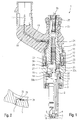
- a first embodiment of a shown in FIG Fuel injector 1 according to the invention is in the Form of a fuel injector 1 for Fuel injection systems from mixture-compressing, spark-ignition internal combustion engines.
- the Fuel injector 1 is particularly suitable for not injecting fuel directly into one Shown combustion chamber of an internal combustion engine.
- the fuel injector 1 consists of a Nozzle body 2, in which a valve needle 3 is arranged.
- the valve needle 3 stands with a valve closing body 4 in Active connection with one on a valve seat body 5 arranged valve seat surface 6 to a sealing seat interacts.
- the fuel injector 1 is acting it is an inward opening in the exemplary embodiment Fuel injector 1, which over several in the Valve seat body 5. Molded spray openings 7 has.
- the nozzle body 2 is against one by a seal 8 Sealed outer pole 9 of a magnetic coil 10.
- the solenoid 10 is encapsulated in a coil housing 11 and on one Coil carrier 12 wound, which on an inner pole 13 of the Solenoid coil 10 is present.
- the inner pole 13 and the outer pole 9 are separated from one another by a constriction 26 and with each other through a non-ferromagnetic Connecting component 29 connected.
- the solenoid 10 is via a line 19 from an electrical Plug contact 17 energized electrical current.
- the Plug contact 17 is from a plastic casing 18 surrounded, which may be molded onto the inner pole 13.
- the valve needle 3 is in a valve needle guide 14 led, which is disc-shaped. to A paired adjusting disc 15 is used for stroke adjustment the other side of the shim 15 is the Anchor 20. This stands over a first flange 21 non-positively in connection with the valve needle 3, which by a weld seam 22 with the first flange 21 connected is. One is supported on the first flange 21 Return spring 23, which in the present design of the Fuel injector 1 through a sleeve 24 Bias is brought.
- Fuel channels 30a to 30b In the valve needle guide 14, in Armature 20 and run on the valve seat body 5 Fuel channels 30a to 30b.
- the fuel is about one central fuel supply 16 supplied and by a Filter element 25 filtered.
- the fuel injector 1 is no further by a seal 28 against one fuel line shown sealed.
- a annular damping element 32 On the spray side of the armature 20 is a annular damping element 32, which consists of a Elastomeric material is arranged. It's on one second flange 31, which has a weld seam 33 is non-positively connected to the valve needle 3.
- Fig. 2 shows an excerpted sectional view 1 marked with II in FIG. 1 from the one in FIG. 1 illustrated embodiment of an invention configured fuel injector 1.
- valve seat body 5 In the valve seat body 5 is that in the detail Spray opening 7 shown enlarged. On An inlet side of the spray opening 7 is in the Valve seat body 5 has a lateral recess 34. A vibration element is in shape in this recess 34 a thread 35 made of metal wires z. B. braided or is spun, attached with a weld spot 36. The Thread 35 is inserted into the spray opening 7 and penetrates the spray opening 7 preferably in full Length.
- the spray opening 7 can instead of in the valve seat body 5 also in a separate from the valve seat body 5 Perforated disk be formed.
Landscapes
- Engineering & Computer Science (AREA)
- Chemical & Material Sciences (AREA)
- Combustion & Propulsion (AREA)
- Mechanical Engineering (AREA)
- General Engineering & Computer Science (AREA)
- Fuel-Injection Apparatus (AREA)
Abstract
Description
- Fig. 1
- einen schematischen Schnitt durch ein erstes Ausführungsbeispiel eines erfindungsgemäß ausgestalteten Brennstoffeinspritzventils und
- Fig. 2
- den Ausschnitt II in der Fig. 1 in einer vergrößerten Darstellung.
Claims (7)
- Brennstoffeinspritzventil (1) für Brennstoffeinspritzanlagen von Brennkraftmaschinen mit einem Aktor (10), einer von dem Aktor (10) betätigbaren Ventilnadel (3) zur Betätigung eines Ventilschließkörpers (4), der zusammen mit einer an einem Ventilsitzkörper (5) ausgebildeten Ventilsitzfläche (6) einen Dichtsitz bildet, und mit zumindest einer Abspritzöffnung (7), die stromabwärts des Ventilsitzes (6) ausgebildet ist,
dadurch gekennzeichnet, daß die Abspritzöffnung (7) von einem elastischen Vibrationselement (35) durchdrungen ist, das auf einer Zulaufseite der Abspritzöffnung (7) befestigt ist und einen Teil des Querschnitts der Abspritzöffnung (7) freiläßt. - Brennstoffeinspritzventil nach Anspruch 1, dadurch gekennzeichnet, daß das Vibrationselement ein Faden (35) ist.
- Brennstoffeinspritzventil nach Anspruch 2, dadurch gekennzeichnet, daß der Faden (35) aus einem temperaturbeständigen Material besteht.
- Brennstoffeinspritzventil nach Anspruch 2 oder 3,
dadurch gekennzeichnet, daß der Faden (35) aus einem Metall besteht. - Brennstoffeinspritzventil nach Anspruch 4,
dadurch gekennzeichnet, daß der Faden (35) in einer seitlichen Ausnehmung (34) auf der Zulaufseite der Abspritzöffnung (7) durch einen Schweißpunkt (36) befestigt ist. - Brennstoffeinspritzventil nach einem der vorherigen Ansprüche,
dadurch gekennzeichnet, daß die wenigstens eine Abspritzöffnung (7) in dem Ventilsitzkörper (5) ausgebildet ist. - Brennstoffeinspritzventil nach einem der Ansprüche 1 bis 5,
dadurch gekennzeichnet, daß die wenigstens eine Abspritzöffnung (7) in einer vom Ventilsitzkörper (5) separaten Lochscheibe ausgebildet ist.
Applications Claiming Priority (2)
| Application Number | Priority Date | Filing Date | Title |
|---|---|---|---|
| DE10124744 | 2001-05-21 | ||
| DE10124744A DE10124744A1 (de) | 2001-05-21 | 2001-05-21 | Brennstoffeinspritzventil |
Publications (2)
| Publication Number | Publication Date |
|---|---|
| EP1260707A2 true EP1260707A2 (de) | 2002-11-27 |
| EP1260707A3 EP1260707A3 (de) | 2004-12-08 |
Family
ID=7685599
Family Applications (1)
| Application Number | Title | Priority Date | Filing Date |
|---|---|---|---|
| EP02011018A Withdrawn EP1260707A3 (de) | 2001-05-21 | 2002-05-17 | Brennstoffeinspritzventil |
Country Status (3)
| Country | Link |
|---|---|
| US (1) | US6598804B2 (de) |
| EP (1) | EP1260707A3 (de) |
| DE (1) | DE10124744A1 (de) |
Families Citing this family (6)
| Publication number | Priority date | Publication date | Assignee | Title |
|---|---|---|---|---|
| US20040083550A1 (en) * | 2002-10-23 | 2004-05-06 | Graebe William F | Air cushion control system |
| US7431226B2 (en) * | 2004-06-03 | 2008-10-07 | Continental Automotive Systems Us, Inc. | Modular fuel injector with a harmonic annular damper member and method of reducing noise |
| US7128281B2 (en) * | 2004-06-03 | 2006-10-31 | Siemens Vdo Automotive Corporation | Modular fuel injector with a damper member and method of reducing noise |
| US7258287B2 (en) * | 2004-06-03 | 2007-08-21 | Siemens Vdo Automotive Corporation | Modular fuel injector with a spiral damper member and method of reducing noise |
| US20050269426A1 (en) * | 2004-06-03 | 2005-12-08 | Cho Yong D | Modular fuel injector with a harmonic damper and method of reducing noise |
| DE102005052255B4 (de) * | 2005-11-02 | 2020-12-17 | Robert Bosch Gmbh | Brennstoffeinspritzventil |
Citations (2)
| Publication number | Priority date | Publication date | Assignee | Title |
|---|---|---|---|---|
| EP0348786B1 (de) | 1988-06-28 | 1992-08-26 | Siemens Aktiengesellschaft | Elektromagnetisches Kraftstoffeinspritzventil |
| DE19804463A1 (de) | 1998-02-05 | 1999-08-12 | Daimler Chrysler Ag | Kraftstoffeinspritzsystem für Ottomotoren |
Family Cites Families (8)
| Publication number | Priority date | Publication date | Assignee | Title |
|---|---|---|---|---|
| DE844378C (de) * | 1950-07-30 | 1952-07-21 | Kloeckner Humboldt Deutz Ag | Kraftstoffeinspritzventil |
| DE3710467C2 (de) * | 1986-05-31 | 1994-05-11 | Bosch Gmbh Robert | Kraftstoffeinspritzventil |
| DE3614564A1 (de) * | 1986-04-29 | 1987-11-05 | Daimler Benz Ag | Einspritzduese zur kraftstoffeinspritzung in den brennraum einer luftverdichtenden einspritzbrennkraftmaschine |
| US4796816A (en) * | 1987-09-21 | 1989-01-10 | Gregory Khinchuk | Impinging-jet fuel injection nozzle |
| DE4331851A1 (de) * | 1993-09-20 | 1995-03-23 | Bosch Gmbh Robert | Lochkörper und Ventil mit Lochkörper |
| DE19541508A1 (de) * | 1995-11-08 | 1997-05-15 | Bosch Gmbh Robert | Kraftstoffeinspritzventil für Brennkraftmaschinen |
| US6109542A (en) * | 1998-09-21 | 2000-08-29 | Cummins Engine Company, Inc. | Servo-controlled fuel injector with leakage limiting device |
| DE19951014A1 (de) * | 1999-07-02 | 2001-01-04 | Bosch Gmbh Robert | Brennstoffeinspritzventil |
-
2001
- 2001-05-21 DE DE10124744A patent/DE10124744A1/de not_active Withdrawn
-
2002
- 2002-05-17 EP EP02011018A patent/EP1260707A3/de not_active Withdrawn
- 2002-05-21 US US10/151,842 patent/US6598804B2/en not_active Expired - Fee Related
Patent Citations (2)
| Publication number | Priority date | Publication date | Assignee | Title |
|---|---|---|---|---|
| EP0348786B1 (de) | 1988-06-28 | 1992-08-26 | Siemens Aktiengesellschaft | Elektromagnetisches Kraftstoffeinspritzventil |
| DE19804463A1 (de) | 1998-02-05 | 1999-08-12 | Daimler Chrysler Ag | Kraftstoffeinspritzsystem für Ottomotoren |
Also Published As
| Publication number | Publication date |
|---|---|
| US20030029930A1 (en) | 2003-02-13 |
| EP1260707A3 (de) | 2004-12-08 |
| DE10124744A1 (de) | 2003-01-23 |
| US6598804B2 (en) | 2003-07-29 |
Similar Documents
| Publication | Publication Date | Title |
|---|---|---|
| EP1623109B1 (de) | Brennstoffeinspritzventil | |
| EP1379773B1 (de) | Brennstoffeinspritzventil | |
| DE10122353B4 (de) | Brennstoffeinspritzventil | |
| EP1370765B1 (de) | Brennstoffeinspritzventil | |
| DE10118164B4 (de) | Brennstoffeinspritzventil | |
| EP1395749B1 (de) | Brennstoffeinspritzventil | |
| EP1434941A1 (de) | Brennstoffeinspritzventil | |
| EP1402176B1 (de) | Brennstoffeinspritzventil | |
| DE10116186A1 (de) | Brennstoffeinspritzventil | |
| EP1633973B1 (de) | Brennstoffeinspritzventil | |
| DE10118276A1 (de) | Brennstoffeinspritzventil | |
| EP1260707A2 (de) | Brennstoffeinspritzventil | |
| EP1195516B1 (de) | Brennstoffeinspritzventil | |
| EP1328725B1 (de) | Brennstoffeinspritzventil | |
| EP1209353B1 (de) | Brennstoffeinspritzventil | |
| EP1702156B1 (de) | Brennstoffeinspritzventil | |
| EP1328724A2 (de) | Brennstoffeinspritzventil | |
| DE10049544A1 (de) | Brennstoffeinspritzventil | |
| WO2003002867A1 (de) | Brennstoffeinspritzventil | |
| EP1258628A2 (de) | Brennstoffeinspritzventil | |
| DE102005024067A1 (de) | Brennstoffeinspritzventil | |
| WO2005021957A1 (de) | Brennstoffeinspritzventil | |
| DE10142300A1 (de) | Brennstoffeinspritzventil | |
| EP1559906A2 (de) | Brennstoffeinspritzventil | |
| EP1197652A2 (de) | Brennstoffeinspritzventil |
Legal Events
| Date | Code | Title | Description |
|---|---|---|---|
| PUAI | Public reference made under article 153(3) epc to a published international application that has entered the european phase |
Free format text: ORIGINAL CODE: 0009012 |
|
| AK | Designated contracting states |
Kind code of ref document: A2 Designated state(s): AT BE CH CY DE DK ES FI FR GB GR IE IT LI LU MC NL PT SE TR |
|
| AX | Request for extension of the european patent |
Free format text: AL;LT;LV;MK;RO;SI |
|
| PUAL | Search report despatched |
Free format text: ORIGINAL CODE: 0009013 |
|
| AK | Designated contracting states |
Kind code of ref document: A3 Designated state(s): AT BE CH CY DE DK ES FI FR GB GR IE IT LI LU MC NL PT SE TR |
|
| AX | Request for extension of the european patent |
Extension state: AL LT LV MK RO SI |
|
| AKX | Designation fees paid | ||
| REG | Reference to a national code |
Ref country code: DE Ref legal event code: 8566 |
|
| STAA | Information on the status of an ep patent application or granted ep patent |
Free format text: STATUS: THE APPLICATION IS DEEMED TO BE WITHDRAWN |
|
| 18D | Application deemed to be withdrawn |
Effective date: 20050609 |