EP1260663B1 - Stay for door, window or similar - Google Patents
Stay for door, window or similar Download PDFInfo
- Publication number
- EP1260663B1 EP1260663B1 EP02360153A EP02360153A EP1260663B1 EP 1260663 B1 EP1260663 B1 EP 1260663B1 EP 02360153 A EP02360153 A EP 02360153A EP 02360153 A EP02360153 A EP 02360153A EP 1260663 B1 EP1260663 B1 EP 1260663B1
- Authority
- EP
- European Patent Office
- Prior art keywords
- tumbler
- operating rod
- driving
- lock
- stay
- Prior art date
- Legal status (The legal status is an assumption and is not a legal conclusion. Google has not performed a legal analysis and makes no representation as to the accuracy of the status listed.)
- Expired - Lifetime
Links
- 230000007246 mechanism Effects 0.000 claims description 22
- 230000009471 action Effects 0.000 claims description 18
- 238000006073 displacement reaction Methods 0.000 claims description 13
- 230000008878 coupling Effects 0.000 claims description 11
- 238000010168 coupling process Methods 0.000 claims description 11
- 238000005859 coupling reaction Methods 0.000 claims description 11
- 210000000056 organ Anatomy 0.000 claims description 11
- 230000002093 peripheral effect Effects 0.000 claims description 2
- 229920002994 synthetic fiber Polymers 0.000 claims description 2
- 230000033001 locomotion Effects 0.000 description 5
- 230000001846 repelling effect Effects 0.000 description 3
- 125000006850 spacer group Chemical class 0.000 description 3
- 238000012550 audit Methods 0.000 description 2
- 230000000694 effects Effects 0.000 description 2
- 235000001674 Agaricus brunnescens Nutrition 0.000 description 1
- 230000003213 activating effect Effects 0.000 description 1
- 230000005540 biological transmission Effects 0.000 description 1
- 230000009849 deactivation Effects 0.000 description 1
- 229940082150 encore Drugs 0.000 description 1
- 230000003993 interaction Effects 0.000 description 1
- 230000035939 shock Effects 0.000 description 1
Images

Classifications
-
- E—FIXED CONSTRUCTIONS
- E05—LOCKS; KEYS; WINDOW OR DOOR FITTINGS; SAFES
- E05C—BOLTS OR FASTENING DEVICES FOR WINGS, SPECIALLY FOR DOORS OR WINDOWS
- E05C17/00—Devices for holding wings open; Devices for limiting opening of wings or for holding wings open by a movable member extending between frame and wing; Braking devices, stops or buffers, combined therewith
- E05C17/02—Devices for holding wings open; Devices for limiting opening of wings or for holding wings open by a movable member extending between frame and wing; Braking devices, stops or buffers, combined therewith by mechanical means
- E05C17/04—Devices for holding wings open; Devices for limiting opening of wings or for holding wings open by a movable member extending between frame and wing; Braking devices, stops or buffers, combined therewith by mechanical means with a movable bar or equivalent member extending between frame and wing
- E05C17/12—Devices for holding wings open; Devices for limiting opening of wings or for holding wings open by a movable member extending between frame and wing; Braking devices, stops or buffers, combined therewith by mechanical means with a movable bar or equivalent member extending between frame and wing consisting of a single rod
- E05C17/16—Devices for holding wings open; Devices for limiting opening of wings or for holding wings open by a movable member extending between frame and wing; Braking devices, stops or buffers, combined therewith by mechanical means with a movable bar or equivalent member extending between frame and wing consisting of a single rod pivoted only at one end and having an elongated slot
- E05C17/166—Security devices
-
- E—FIXED CONSTRUCTIONS
- E05—LOCKS; KEYS; WINDOW OR DOOR FITTINGS; SAFES
- E05C—BOLTS OR FASTENING DEVICES FOR WINGS, SPECIALLY FOR DOORS OR WINDOWS
- E05C9/00—Arrangements of simultaneously actuated bolts or other securing devices at well-separated positions on the same wing
- E05C9/02—Arrangements of simultaneously actuated bolts or other securing devices at well-separated positions on the same wing with one sliding bar for fastening when moved in one direction and unfastening when moved in opposite direction; with two sliding bars moved in the same direction when fastening or unfastening
- E05C9/025—Arrangements of simultaneously actuated bolts or other securing devices at well-separated positions on the same wing with one sliding bar for fastening when moved in one direction and unfastening when moved in opposite direction; with two sliding bars moved in the same direction when fastening or unfastening with pins engaging slots
-
- E—FIXED CONSTRUCTIONS
- E05—LOCKS; KEYS; WINDOW OR DOOR FITTINGS; SAFES
- E05B—LOCKS; ACCESSORIES THEREFOR; HANDCUFFS
- E05B15/00—Other details of locks; Parts for engagement by bolts of fastening devices
- E05B15/0013—Followers; Bearings therefor
-
- E—FIXED CONSTRUCTIONS
- E05—LOCKS; KEYS; WINDOW OR DOOR FITTINGS; SAFES
- E05B—LOCKS; ACCESSORIES THEREFOR; HANDCUFFS
- E05B15/00—Other details of locks; Parts for engagement by bolts of fastening devices
- E05B15/0053—Other details of locks; Parts for engagement by bolts of fastening devices means providing a stable, i.e. indexed, position of lock parts
-
- E—FIXED CONSTRUCTIONS
- E05—LOCKS; KEYS; WINDOW OR DOOR FITTINGS; SAFES
- E05B—LOCKS; ACCESSORIES THEREFOR; HANDCUFFS
- E05B15/00—Other details of locks; Parts for engagement by bolts of fastening devices
- E05B15/16—Use of special materials for parts of locks
- E05B15/1635—Use of special materials for parts of locks of plastics materials
-
- E—FIXED CONSTRUCTIONS
- E05—LOCKS; KEYS; WINDOW OR DOOR FITTINGS; SAFES
- E05B—LOCKS; ACCESSORIES THEREFOR; HANDCUFFS
- E05B63/00—Locks or fastenings with special structural characteristics
- E05B63/0065—Operating modes; Transformable to different operating modes
- E05B63/0069—Override systems, e.g. allowing opening from inside without the key, even when locked from outside
-
- E—FIXED CONSTRUCTIONS
- E05—LOCKS; KEYS; WINDOW OR DOOR FITTINGS; SAFES
- E05B—LOCKS; ACCESSORIES THEREFOR; HANDCUFFS
- E05B63/00—Locks or fastenings with special structural characteristics
- E05B63/04—Locks or fastenings with special structural characteristics for alternative use on the right-hand or left-hand side of wings
Definitions
- the invention relates to a door and window interlock lock or the like, comprising, housed in a housing, a mechanism for control provided capable of pushing back, from an erased position in this case in a projecting position relative to the edge before the latter and vice versa, a fastening member to even to cooperate with a crank lever, this mechanism order comprising, on the one hand, at least one follower and, on the other hand, an easel provided capable of being made integral an operating rod corresponding to a lever or lever lock for controlling the erasure of said attachment member under the impulse of said operating rod during a displacement of the latter in a determined direction, including unlocking.
- the present invention relates to the field of hardware building and relates, in particular, to crackers of doors, windows or the like.
- a door, window or the like in the form of a lever, one end of which is articulated, by means of a support, in the rebate of the front upright of the frame sleeping.
- this lever can pivot around a parallel axis in the plane of said door or the like, either perpendicular to the front pillar of the sleeping frame.
- the end opposite of this lever is able to cooperate with an organ maneuverable hooking by means of a button control and mounted in a box at the front upright opening correspondent.
- the command button acts, by via a maneuvering square, on a locator in said housing provided capable of being embedded in the edge before opening it. So, under the influence of the rotation of the control button, the follower attacks the latching member, more particularly in the form of a bolt, which then comes move in the plane of the opening so as to present itself, as the case may be, in the projecting position or in the retracted position by report to the front song of this opening.
- This includes a locking member whose tail extends into this case, while the head in the form of mushroom is provided capable of emerging from the aforementioned headrest, this through an appropriate opening.
- the mechanism of this crank lock includes a follower on which a spring acts allowing keep the handle, as appropriate, in an upright position lock or in a horizontal unlocked position.
- This follower also has a cooperating control finger with a notch in the tail of the organ of locking, knowing that in the locked position the end of this control finger is located in the extension of a plane stop preventing said locking member from being able to be pushed back, by direct action on the latter, in a position retracted.
- Said mechanism also includes a mounted lever articulated in its housing and comprising a first arm of which the end cooperates, just like the tail of the organ of locking, with the follower control finger. It is still provided with a second arm, the end of which is suitable, when the air lock is activated, be located on the trajectory of a coach associated with the operating rod.
- this coach can be brought into a inactive position, by action on said lever, when it is commanded the unlocking of the lever or lever-bolt.
- the trainer acts on the second arm of this lever whose end of the first arm controls the rotation of the follower and, thereby, the removal of the organ from locking.
- This lock also includes declutching means which prevent any action on the attachment member by the bridge in the event of movement of the operating rod from a position unlocked towards a locked position.
- declutching means which prevent any action on the attachment member by the bridge in the event of movement of the operating rod from a position unlocked towards a locked position.
- the tail of the latching member is also able to act a follower. More particularly, in the lower part of said tail has a toothing on which comes to mesh teeth corresponding to the follower.
- crank lock allows again to make active, i.e. to command the advance of the fastening member directly by action on the mechanism control of the lever or lever-bolt. So, starting from a lock position and assuming the lock is still inactive, a first order of unlocking generates the advancement of the fastening member. he then agree to lock and unlock the door by action on the lever or lever-lock for cause it to recede.
- this solution according to the invention makes it possible to act directly on the hooking member of a crank lock through a cremone bolt or locking bolt. In fact, this action on the fastening member occurs beyond of a first race, which allows, as will appear further on, to keep the safety function through which the fastening member, abutting against the finger control of the follower, cannot be pushed back by action direct inside the lock case.
- the present invention relates to the field of doors, windows or the like and, more particularly, at a crank lock 1 capable of fitting in particular opening it from such a door, window or other 2.
- such a stay lock 1 comprises, housed in a case 3 taking position, for example, in a notch provided for this purpose in rebate 4 of the opening 5, a mechanism for control 6 provided capable of repelling a fastening member 7 in an erased position inside the housing 3 or, at otherwise, in a position, as visible in Figure 1, projecting at this rebate 4 of the opening 5.
- this hooking member 7 is designed to cooperate with a lever for the stay 8 arranged in correspondence on the sleeping frame 9 of this door, window or other 2.
- the lock advantageously, means 1 coupling 10 of its control mechanism 6 with a operating rod 11 (more particularly visible in the Figures 2 to 4) corresponding to a bolt or bolt lock 12 that is fitted to the opening 5 of the door, window or the like 2.
- these coupling means 10 are intended to ensure the erasure of the attachment member 7 of this lock spacer 1 under the impulse of said operating rod 11 when moving the latter in one direction determined, more particularly, but not exclusively, to unlocking 13.
- declutching means. 14 designed capable of disengaging said means coupling 10 relative to the control mechanism 6 of the lock 1, under the effect of the displacement of this rod maneuver 11 in a reverse direction 15, in particular of locking.
- this comprises, housed in the housing 3, a follower 16 on which a button can rotate 17, visible in Figure 1, through a square operating 18.
- This follower 16 has a first drive finger 19 provided able to cooperate with the tail 20 extending in the housing 3 of the fastening member 7 so as to push it back in a projecting position relative to the rebate 4 of the opening 5 and therefore capable of cooperating with the lever to ensure its erasure in said housing 3.
- the housing 3, as visible in Figures 2 to 4 can be secured to a headrest 22 capable of extending over the whole rebate height 4 of the opening 5, such that represented in FIG. 1.
- the operating rod 11 it is provided able to circulate at the rear of this headrest 22, in particular between the latter and the housing 3 of the lock of the brace 1.
- Such an operating rod 11 comprises, for this purpose, oblong openings for passage fixing means 23 of the housing 3 on said headrest 22 and the passage of the fastening member 7.
- the coupling means 10 consist, substantially in a transmission organ more particularly an easel 24, mounted movably in the housing 3 parallel to the operating rod 11 and provided capable of being made in solidarity with the latter through one of its ends 25. At its other end 26, this easel 24 comes cooperate with the follower 16 for, under the impetus of said operating rod 11 in the unlocking direction 13, ensure the rotational drive of this follower 16 and the recoil of the fastening member 7.
- the easel 24 has a drive pin 27 provided adapted to act on a second drive finger 28 associated with said audit follower 16.
- this easel 24 still has a second drive pin 29 provided capable of cooperating, beyond a race 30, with a track 31 of a cam 32 corresponding to a trainer 33 associated with the tail 20 of the attachment member 7.
- these declutching means 14 consist of drive pins, respectively 27 and 29, associated with easel 24 and retractable type with respect to, respectively, the second drive finger 28 of the follower 16 and the cam 32 of the coach 33, this within the framework of a relative displacement of these elements relative to each other in this locking direction 15, ie starting from the position of the easel 24 as shown in Figure 2 to reach the position corresponding to figure 3.
- these drive pins 27, 29 are rendered secured to elastic means 35, 36 of positional reminders active, i.e. able to cooperate, as appropriate, with the second drive finger 28 of the follower 16 or the cam 32.
- These drive pins 27, 29 are still beveled, at least on one side 37, 38, so as to allow them to be repelled in an inactive position, i.e. deleted, under the pulse, respectively of the second drive finger 28 and of cam 32, in the context of a relative displacement of the easel 24, secured to the operating rod 11, in a direction 15, more particularly for locking the cremone bolt or bolt lock 12.
- these drive pins 27, 29 also include a stop plane 39, 40 for repelling the second finger 28 of the follower 16 or the coach 33 to across track 31 of cam 32, when these elements are find on their way when ordering on the move easel 24 driven by the operating rod 11 in unlocking direction 13.
- this crank lock 1 can be provided with indexing means 41 of the angular positions 42, 43 of the follower 16 corresponding to the active and inactive position of this crane lock 1.
- indexing means 41 are defined according to a preferred embodiment, on the one hand, by a housing 44 in the housing 3 provided, at its peripheral wall, of recesses 45 in which is able to engage, elastically and in angular positions mentioned above, at least one indexing boss 46 which, on its periphery, said follower 16.
- this follower 16 can be made of synthetic material, while said indexing boss 46 is advantageously positioned on a elastic blade 47 drawn on this periphery of said follower 16.
Abstract
Description
L'invention concerne un verrou entrebâilleur de porte, fenêtre ou analogue, comportant, logé dans un boítier, un mécanisme de commande prévu apte à repousser, depuis une position effacée dans ce boítier dans une position saillante par rapport au chant avant de ce dernier et inversement, un organe d'accrochage à même de coopérer avec un levier entrebâilleur, ce mécanisme de commande comportant, d'une part, au moins un fouillot et, d'autre part, un chevalet prévu apte à être rendu solidaire d'une tringle de manoeuvre correspondant à une crémone ou crémone serrure pour commander l'effacement dudit organe d'accrochage sous l'impulsion de ladite tringle de manoeuvre lors d'un déplacement de cette dernière dans une direction déterminée, notamment déverrouillage.The invention relates to a door and window interlock lock or the like, comprising, housed in a housing, a mechanism for control provided capable of pushing back, from an erased position in this case in a projecting position relative to the edge before the latter and vice versa, a fastening member to even to cooperate with a crank lever, this mechanism order comprising, on the one hand, at least one follower and, on the other hand, an easel provided capable of being made integral an operating rod corresponding to a lever or lever lock for controlling the erasure of said attachment member under the impulse of said operating rod during a displacement of the latter in a determined direction, including unlocking.
La présente invention concerne le domaine de la quincaillerie du bâtiment et a trait, tout particulièrement, à des entrebâilleurs de portes, fenêtres ou analogues.The present invention relates to the field of hardware building and relates, in particular, to crackers of doors, windows or the like.
Il est connu, notamment par le document FR-A-2.734.015, un entrebâilleur pour porte, fenêtre ou analogue qui se présente sous forme d'un levier dont une extrémité est montée articulée, au moyen d'un support, en feuillure du montant avant du cadre dormant. Ainsi, ce levier peut pivoter autour d'un axe parallèle au plan de ladite porte ou analogue, soit perpendiculairement au montant avant du cadre dormant. Par ailleurs, l'extrémité opposée de ce levier est à même de coopérer avec un organe d'accrochage manoeuvrable par l'intermédiaire d'un bouton de commande et monté dans un boítier au niveau du montant avant correspondant de l'ouvrant.It is known, in particular from document FR-A-2.734.015, a door, window or the like in the form of a lever, one end of which is articulated, by means of a support, in the rebate of the front upright of the frame sleeping. Thus, this lever can pivot around a parallel axis in the plane of said door or the like, either perpendicular to the front pillar of the sleeping frame. By the way, the end opposite of this lever is able to cooperate with an organ maneuverable hooking by means of a button control and mounted in a box at the front upright opening correspondent.
Plus précisément, le bouton de commande agit, par l'intermédiaire d'un carré de manoeuvre, sur un fouillot implanté dans ledit boítier prévu apte à être encastré dans le chant avant de l'ouvrant. Ainsi, sous l'influence de la rotation du bouton de commande, le fouillot attaque l'organe d'accrochage, plus particulièrement sous forme d'un pêne, qui vient, alors, se déplacer dans le plan de l'ouvrant de manière à se présenter, selon le cas, en position saillante ou en position escamotée par rapport audit chant avant de cet ouvrant.More specifically, the command button acts, by via a maneuvering square, on a locator in said housing provided capable of being embedded in the edge before opening it. So, under the influence of the rotation of the control button, the follower attacks the latching member, more particularly in the form of a bolt, which then comes move in the plane of the opening so as to present itself, as the case may be, in the projecting position or in the retracted position by report to the front song of this opening.
Il est précisé, dans ce document qu'en cas d'équipement de l'ouvrant d'une crémone ou crémone-serrure, comportant une têtière s'étendant sur toute la hauteur de ce chant avant de l'ouvrant, le boítier du verrou entrebâilleur peut être rendu solidaire de cette têtière, celle-ci comportant par ailleurs une ouverture autorisant le passage du pêne correspondant à l'organe d'accrochage.It is specified in this document that in case of equipment of opening a cremone bolt or bolt lock, comprising a headrest extending over the entire height of this edge before the opening, the housing of the ajar lock can be returned in solidarity with this headrest, the latter also comprising a opening allowing the passage of the bolt corresponding to the organ hooking.
Celui-ci est de section rectangulaire et comporte un rétrécissement dans sa partie susceptible de se présenter saillante par rapport au chant avant de l'ouvrant. Ainsi, lorsque cet organe d'accrochage vient coopérer avec l'extrémité du levier, plus précisément lorsque sa partie saillante est engagée dans l'ouverture oblongue ménagée à cet effet dans cette extrémité du levier, elle remplit la fonction d'un bouton dans une boutonnière. Dans ces conditions, au moment d'activer l'entrebâilleur, l'organe d'accrochage et l'ouverture oblongue sont dans un même alignement vertical. Puis, en entrebâillant l'ouvrant, le levier bascule autour de son axe de pivotement, alors que son extrémité libre avec la lumière oblongue pivote autour du rétreint correspondant à l'organe d'accrochage. Celui-ci n'étant plus dans le prolongement de cette ouverture oblongue dudit levier, il ne peut en être retiré volontairement, que ce soit par une action directe sur ce levier ou sur l'organe d'accrochage.This is of rectangular section and has a narrowing in its part likely to appear protruding from the edge before the opening. So, when this attachment member cooperates with the end of the lever, more precisely when its protruding part is engaged in the oblong opening made for this purpose in this end of the lever, it performs the function of a button in a buttonhole. Under these conditions, when activating the ajar, the fastening member and the oblong opening are in the same vertical alignment. Then, half-opening opening it, the lever swings around its pivot axis, while its free end with the oblong light pivots around the constriction corresponding to the attachment member. This one no longer in the extension of this oblong opening said lever, it can only be removed voluntarily, either by direct action on this lever or on the organ hooking.
L'on remarquera que si de tels entrebâilleurs sont, finalement, très discrets, en ce sens que l'ensemble de leurs éléments constitutifs est susceptible de prendre position dans un entaillage de l'ouvrant et en feuillure du cadre dormant et s'ils peuvent être rendus actifs très facilement, ils n'en sont pas moins contraignants à la commande d'ouverture d'un ouvrant, en particulier lorsque celui-ci est pourvu, par ailleurs, d'une ferrure de verrouillage de type multipoints , tel qu'une crémone ou crémone-serrure.It will be noted that if such a cracker is, ultimately, very discreet, in the sense that all of their elements is likely to take a position in a notching of the sash and in the rebate of the frame and if they can be made active very easily, they are not no less restrictive to the command to open an opening, in particular when the latter is otherwise provided with a multi-point locking hardware, such as a lever or lock-bolt.
L'on comprend, en effet, que lorsque l'ouvrant d'une porte ou fenêtre a été refermé sur son cadre dormant et qu'au travers du mécanisme de commande de la crémone ou crémone-serrure celle-ci a été amenée en position de verrouillage, cet entrebâilleur n'est plus d'aucune utilité et il est inutile qu'il soit maintenu actif. A ce propos, si, au moment de verrouiller la porte ou fenêtre l'usager, ayant activé préalablement l'entrebâilleur, omet de le désactiver, il est fort probable qu'il l'oubliera également lorsqu'il cherchera à ouvrir, à nouveau, cette porte ou fenêtre. Aussi, il ne s'en rendra compte, probablement, qu'au travers d'une tentative d'ouverture de l'ouvrant qui sera finalement empêchée au-delà d'une course correspondant à l'amplitude de mouvement qu'autorise l'entrebâilleur. Etant nécessairement pris par surprise, il risque fort d'imprimer un choc brutal à l'ouvrant lorsque entre en action l'entrebâilleur, ce qui, non seulement, a pour conséquence de solliciter, fortement, les pièces de cet entrebâilleur, mais également la menuiserie. Par ailleurs, cela représente un risque d'accident pour cet usager qui, lui-même, peut buter contre l'ouvrant, s'attendant normalement à une ouverture sans résistance.It is understood, in fact, that when the opening of a door or window has been closed on its sleeping frame and that through the cremone bolt control mechanism or cremone bolt has been brought into the locking position, this spacer is no longer of any use and there is no point in it being kept active. In this regard, if, when locking the door or window the user, having previously activated the opener, omits to deactivate it, it is very likely that he will also forget it when he seeks to open, to new, that door or window. Also, he will never go probably account that through an attempt to open of the opening which will ultimately be prevented beyond a race corresponding to the range of motion allowed the door guard. Being necessarily taken by surprise, it strong risk of giving a brutal shock to the sash when entering in action the opener, which not only has the consequence of soliciting, strongly, the parts of this but also carpentry. By the way, this represents a risk of accident for this user who, himself, may abut the sash, normally expecting a opening without resistance.
A ce propos, il est encore connu par le document DE-198 15 671 une ferrure de verrouillage, de type crémone, comportant un mécanisme principal, permettant d'agir, en particulier par l'intermédiaire d'une poignée, sur une tringle de manoeuvre s'étendant à l'arrière d'une têtière. Au travers de ce mécanisme de commande principal il est possible d'intervenir sur un pêne demi-tour et sur un pêne à crochet. A l'arrière de la têtière est encore rapporté le boítier d'un verrou d'entrebâilleur. In this regard, it is also known from document DE-198 15 671 a locking fitting, of the lever type, comprising a main mechanism for action, in particular by via a handle, on an operating rod extending to the back of a headrest. Through this mechanism main command it is possible to work on a bolt turn around and on a hook bolt. At the back of the headrest is still reported the housing of a crank lock.
Celui-ci comporte un organe de verrouillage dont la queue s'étend dans de ce boítier, tandis que la tête en forme de champignon est prévue apte à émerger de la têtière précitée, ceci au travers d'une ouverture appropriée.This includes a locking member whose tail extends into this case, while the head in the form of mushroom is provided capable of emerging from the aforementioned headrest, this through an appropriate opening.
Ainsi, cet organe de verrouillage peut occuper trois positions distinctes :
- une première rétractée par rapport à la face avant de la têtière ;
- une deuxième où il coopère avec un loquet d'entrebâilleur ;
- et une troisième dans laquelle il vient finalement s'insérer dans l'ouverture d'une gâche sur le dormant.
- a first retracted with respect to the front face of the headrest;
- a second where it cooperates with a crank latch;
- and a third in which it finally fits into the opening of a strike on the frame.
Tout particulièrement, le mécanisme de ce verrou d'entrebâilleur comporte un fouillot sur lequel agit un ressort permettant de maintenir la poignée, selon le cas, dans une position verticale de verrouillage ou dans une position déverrouillée horizontale. Ce fouillot comporte encore un doigt de commande qui coopère avec une échancrure ménagée dans la queue de l'organe de verrouillage, sachant qu'en position verrouillée l'extrémité de ce doigt de commande se situe dans le prolongement d'un plan butée empêchant que ledit organe de verrouillage puisse être repoussé, par action directe sur ce dernier, dans une position rétractée. Ledit mécanisme comporte encore un levier monté articulé dans son boítier et comportant un premier bras dont l'extrémité coopère, tout comme la queue de l'organe de verrouillage, avec le doigt de commande du fouillot. Il est encore pourvu d'un second bras dont l'extrémité est apte, lorsque le verrou entrebâilleur est rendu actif, à se situer sur la trajectoire d'un entraíneur associé à la tringle de manoeuvre. In particular, the mechanism of this crank lock includes a follower on which a spring acts allowing keep the handle, as appropriate, in an upright position lock or in a horizontal unlocked position. This follower also has a cooperating control finger with a notch in the tail of the organ of locking, knowing that in the locked position the end of this control finger is located in the extension of a plane stop preventing said locking member from being able to be pushed back, by direct action on the latter, in a position retracted. Said mechanism also includes a mounted lever articulated in its housing and comprising a first arm of which the end cooperates, just like the tail of the organ of locking, with the follower control finger. It is still provided with a second arm, the end of which is suitable, when the air lock is activated, be located on the trajectory of a coach associated with the operating rod.
Plus précisément, au travers de cet entraíneur et partant d'une position de verrouillage de ladite tringle de manoeuvre alors que l'entrebâilleur est actif, celui-ci peut être amené dans une position inactive, par action sur ledit levier, lorsqu'il est commandé le déverrouillage de la crémone ou crémone-serrure. Dans ce cas l'entraíneur agit sur le second bras de ce levier dont l'extrémité du premier bras commande la rotation du fouillot et, par là même, le retrait de l'organe de verrouillage.More precisely, through this coach and starting from a locking position of said operating rod while the ajar is active, it can be brought into a inactive position, by action on said lever, when it is commanded the unlocking of the lever or lever-bolt. In this case the trainer acts on the second arm of this lever whose end of the first arm controls the rotation of the follower and, thereby, the removal of the organ from locking.
Inversement, lorsque l'entrebâilleur est rendu actif alors que la crémone ou crémone-serrure est, elle, déverrouillée, il peut être obtenu le verrouillage de cette dernière sans qu'il y ait une interaction sur cet entrebâilleur, l'entraíneur dont est équipée la tringle de manoeuvre étant susceptible de s'effacer, élastiquement, devant l'extrémité du second bras correspondant au levier.Conversely, when the ajar is made active while the cremone bolt or locking bolt is unlocked, it can be obtained the lock of the latter without there being an interaction on this ajar, the coach of which is equipped with the operating rod being liable to fade, elastically, in front of the end of the corresponding second arm to the lever.
De la description du document de l'état de la technique qui précède, il ressort que les moyens d'accouplement qui sont prévus aptes à coopérer avec la tringle de manoeuvre commandent l'effacement de l'organe de verrouillage ou organe d'accrochage par action, exclusivement, sur le fouillot du verrou entrebâilleur. L'on comprend bien que pour commander cette rotation et, par son intermédiaire, le recul de l'organe d'accrochage, il convient de lui appliquer un couple non négligeable si l'on tient compte, en particulier, du faible bras de levier que procure le doigt d'entraínement par rapport à l'axe de rotation du fouillot.Description of the prior art document which above, it appears that the coupling means which are provided able to cooperate with the operating rod control erasure of the locking member or latching member by action, exclusively, on the lock follower door guard. We understand that to order this rotation and, through it, the recoil of the organ attachment, apply a torque not negligible if we take into account, in particular, the weak arm lever provided by the drive finger relative to the axis of rotation of the follower.
L'on connaít également, par le document EP-0 823 521, un verrou d'entrebâilleur associé à une ferrure de verrouillage, du type crémone ou crémone-serrure. Celui-ci comporte un chevalet monté solidaire en translation d'une tringle de manoeuvre et qui, partant d'une position de verrouillage de cette dernière, est capable de commander le retrait de l'organe d'accrochage de ce verrou d'entrebâilleur, lors d'une commande de déverrouillage de ladite crémone ou crémone-serrure. Plus précisément, ce chevalet est pourvu d'un doigt de commande venant se déplacer dans une lumière en forme de bouteille renversée que comporte, intérieurement au boítier du verrou d'entrebâilleur, la queue d'un organe d'accrochage.We also know, from document EP-0 823 521, a lock of the bracing device associated with a locking fitting, of the type cremone bolt or bolt lock. This one has a mounted easel integral in translation with an operating rod and which, starting from a locking position of the latter, is able to control the removal of the fastening member from this crank lock, when unlocking command said cremone bolt or bolt lock. More specifically, this easel is provided with a control finger moving in a light in the shape of an inverted bottle, internally to the crankcase lock housing, the tail a fastening member.
Ce verrou comporte encore des moyens de débrayage qui empêchent toute action sur l'organe d'accrochage par le chevalet en cas de déplacement de la tringle de manoeuvre depuis une position déverrouillée en direction d'une position de verrouillage. Sur la queue de l'organe d'accrochage est également en mesure d'agir un fouillot. Plus particulièrement, en partie inférieure ladite queue comporte une denture sur laquelle vient s'engrener une denture correspondant au fouillot.This lock also includes declutching means which prevent any action on the attachment member by the bridge in the event of movement of the operating rod from a position unlocked towards a locked position. Sure the tail of the latching member is also able to act a follower. More particularly, in the lower part of said tail has a toothing on which comes to mesh teeth corresponding to the follower.
Finalement, la conception de ce verrou entrebâilleur permet encore de rendre actif, c'est à dire de commander l'avancée de l'organe d'accrochage directement par action sur le mécanisme de commande de la crémone ou crémone-serrure. Ainsi, partant d'une position de verrouillage et à supposer que le verrou entrebâilleur soit inactif, une première commande de déverrouillage engendre l'avancée de l'organe d'accrochage. Il convient ensuite de verrouiller et de déverrouiller à nouveau la porte par action sur la crémone ou crémone-serrure pour provoquer son recul.Finally, the design of this crank lock allows again to make active, i.e. to command the advance of the fastening member directly by action on the mechanism control of the lever or lever-bolt. So, starting from a lock position and assuming the lock is still inactive, a first order of unlocking generates the advancement of the fastening member. he then agree to lock and unlock the door by action on the lever or lever-lock for cause it to recede.
En fait, l'invention concerne un verrou d'entrebâilleur, de porte, fenêtre ou analogue, comportant, logé dans un boítier, un mécanisme de commande prévu apte à repousser, depuis une position effacée dans ce boítier dans une position saillante par rapport au chant avant de ce dernier et inversement, un organe d'accrochage à même de coopérer avec un levier d'entrebâilleur, ledit mécanisme de commande comportant, d'une part, au moins un fouillot et, d'autre part, un chevalet prévu apte à être rendu solidaire d'une tringle de manoeuvre correspondant à une crémone ou crémone-serrure pour commander l'effacement dudit organe d'accrochage sous l'impulsion de ladite tringle de manoeuvre lors d'un déplacement de cette dernière dans une direction déterminée, notamment déverrouillage, caractérisée par le fait que :
- ledit chevalet comporte un premier ergot d'entraínement à même d'agir sur un doigt d'entraínement associé au fouillot et un second ergot d'entraínement prévu apte à coopérer, au-delà d'une course, avec une piste d'une came correspondant à un entraíneur associé à la queue de l'organe d'accrochage sous l'impulsion de la tringle de manoeuvre lors du déplacement de cette dernière dans ladite direction déterminée, notamment de déverrouillage ;
- lesdits ergots d'entraínement sont prévus de type escamotable, respectivement, par rapport audit doigt d'entraínement du fouillot et à la came de l'entraíneur, dans le cadre d'un déplacement relatif de ces éléments les uns par rapport aux autres, lors d'un déplacement en sens inverse de ladite tringle de manoeuvre, notamment de verrouillage.
- said bridge comprises a first drive pin capable of acting on a drive finger associated with the follower and a second drive pin provided capable of cooperating, beyond a stroke, with a track of a cam corresponding to a driver associated with the tail of the latching member under the impulse of the operating rod when the latter moves in said determined direction, in particular for unlocking;
- said drive pins are provided of retractable type, respectively, relative to said drive finger of the follower and to the coach's cam, in the context of a relative movement of these elements relative to each other, during movement in the opposite direction of said operating rod, in particular for locking.
En somme, cette solution selon l'invention permet d'agir directement sur l'organe d'accrochage d'un verrou entrebâilleur au travers d'une tringle de manoeuvre de crémone ou crémone-serrure. En fait, cette action sur l'organe d'accrochage intervient au-delà d'une première course, ce qui permet, comme cela apparaítra plus loin, de conserver la fonction sécurité au travers de laquelle l'organe d'accrochage, venant en butée contre le doigt de commande du fouillot, ne peut être repoussé par action directe à l'intérieur du boítier du verrou. In short, this solution according to the invention makes it possible to act directly on the hooking member of a crank lock through a cremone bolt or locking bolt. In fact, this action on the fastening member occurs beyond of a first race, which allows, as will appear further on, to keep the safety function through which the fastening member, abutting against the finger control of the follower, cannot be pushed back by action direct inside the lock case.
Finalement, il découle de la présente invention une particulière aisance au niveau de la commande de la crémone ou crémone-serrure susceptible d'agir sur ce verrou d'entrebâilleur.Finally, it follows from the present invention a particular ease of control of the lever or lever-bolt likely to act on this crank lock.
L'invention sera mieux comprise à la lecture de la description qui va suivre et en se référant aux dessins ci-joints se rapportant à un mode de réalisation.
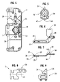
- la figure 1 est une représentation schématisée et en position entrebâillée d'une porte équipée d'un verrou d'entrebâilleur conforme à l'invention ;
- la figure 2 est une représentation schématisée et en plan
du verrou d'entrebâilleur conforme à l'invention, l'une des
parois du boítier ayant été retirée laissant apparentes les
pièces de son mécanisme de commande dans leur position
correspondant :
- au verrou d'entrebâilleur rendu actif ;
- la tringle de manoeuvre correspondant à une ferrure de type crémone ou crémone-serrure repoussée dans sa position déverrouillée ;
- la figure 3 est une vue similaire à la figure 2 et illustre la position occupée par les différentes pièces du mécanisme de commande du verrou entrebâilleur lorsque celui-ci est en position active et que la tringle de manoeuvre de la crémone ou crémone serrure est dans sa position verrouillée.
- la figure 4 représente, là encore, une vue similaire aux figures 2 et 3 du verrou d'entrebâilleur, sachant que partant de la position correspondant à la figure 3, la tringle de manoeuvre de la crémone ou crémone-serrure a été repoussée en position déverrouillée, commande ayant permis de désactiver l'entrebâilleur.
- la figure 5 est une représentation schématisée et en plan du fouillot correspondant au mécanisme de commande du verrou d'entrebâilleur ;
- la figure 6 est une représentation schématisée et en plan du chevalet correspondant à ce mécanisme de commande ;
- la figure 7 est une illustration de ce chevalet vu en élévation ;
- la figure 8 est une représentation schématisée et en plan de l'organe d'accrochage du verrou entrebâilleur ;
- la figure 9 est une vue schématisée et en plan d'un entraíneur prévu apte à être rendu solidaire dudit organe d'accrochage.
- Figure 1 is a schematic representation in the ajar position of a door equipped with a crank lock according to the invention;
- FIG. 2 is a diagrammatic and plan representation of the crank lock according to the invention, one of the walls of the housing having been removed leaving visible the parts of its control mechanism in their corresponding position:
- to the active door lock;
- the operating rod corresponding to a cremone bolt or bolt-lock type pushed back into its unlocked position;
- FIG. 3 is a view similar to FIG. 2 and illustrates the position occupied by the various parts of the mechanism for controlling the crank lock when the latter is in the active position and the rod for operating the cremone bolt or cremone bolt is in its locked position.
- FIG. 4 shows, here again, a view similar to FIGS. 2 and 3 of the crank lock, knowing that starting from the position corresponding to FIG. 3, the operating rod for the cremone bolt or cremone bolt has been pushed back into position unlocked, command enabling deactivation of the opener.
- FIG. 5 is a diagrammatic and plan view of the follower corresponding to the mechanism for controlling the linkage lock;
- Figure 6 is a schematic and plan view of the bridge corresponding to this control mechanism;
- Figure 7 is an illustration of this easel seen in elevation;
- FIG. 8 is a diagrammatic and plan view of the hooking member of the crankshaft lock;
- Figure 9 is a schematic plan view of a coach provided capable of being secured to said attachment member.
Tel que représenté dans la figure 1 des dessins ci-joints, la présente invention a trait au domaine des entrebâilleurs de portes, fenêtres ou analogues et, plus particulièrement, à un verrou d'entrebâilleur 1 susceptible d'équiper en particulier l'ouvrant d'une telle porte, fenêtre ou autre 2.As shown in Figure 1 of the accompanying drawings, the present invention relates to the field of doors, windows or the like and, more particularly, at a crank lock 1 capable of fitting in particular opening it from such a door, window or other 2.
Ainsi, un tel verrou d'entrebâilleur 1 comporte, logé dans un
boítier 3 prenant position, par exemple, dans un entaillage
prévu à cet effet en feuillure 4 de l'ouvrant 5, un mécanisme de
commande 6 prévu apte à repousser un organe d'accrochage 7 dans
une position effacée à l'intérieur du boítier 3 ou, au
contraire, dans une position, tel que visible dans la figure 1,
saillante au niveau de cette feuillure 4 de l'ouvrant 5.Thus, such a stay lock 1 comprises, housed in a
Dans cette position saillante, cet organe d'accrochage 7 est
prévu pour coopérer avec un levier d'entrebâilleur 8 disposé en
correspondance sur le cadre dormant 9 de cette porte, fenêtre ou
autre 2.In this projecting position, this hooking
A ce propos, l'on se reportera tout particulièrement au document FR-A-2.734.015 pour plus de détails quant au fonctionnement d'un tel entrebâilleur.In this regard, particular reference is made to the document FR-A-2.734.015 for more details on the operation of a like a cracker.
Pour en revenir à l'objet de la présente invention, le verrou
d'entrebâilleur 1 comporte, avantageusement, des moyens
d'accouplement 10 de son mécanisme de commande 6 avec une
tringle de manoeuvre 11 (plus particulièrement visible dans les
figures 2 à 4) correspondant à une crémone ou crémone-serrure 12
que vient équiper l'ouvrant 5 de la porte, fenêtre ou analogue
2.To return to the subject of the present invention, the lock
advantageously, means 1
En fait, ces moyens d'accouplement 10 sont destinés à assurer
l'effacement de l'organe d'accrochage 7 de ce verrou
entrebâilleur 1 sous l'impulsion de ladite tringle de manoeuvre
11 lors du déplacement de cette dernière dans une direction
déterminée, plus particulièrement, mais non exclusivement, de
déverrouillage 13.In fact, these coupling means 10 are intended to ensure
the erasure of the
Par ailleurs, ils viennent coopérer avec des moyens de débrayage
14 conçus aptes à assurer le débrayage desdits moyens
d'accouplement 10 par rapport au mécanisme de commande 6 du
verrou 1, sous l'effet du déplacement de cette tringle de
manoeuvre 11 dans une direction inverse 15, notamment de
verrouillage.Furthermore, they cooperate with declutching means.
14 designed capable of disengaging said means
coupling 10 relative to the control mechanism 6 of the
lock 1, under the effect of the displacement of this
Pour en revenir au mécanisme de commande 6 du verrou
d'entrebâilleur 1, celui-ci comporte, logé dans le boítier 3, un
fouillot 16 sur lequel est à même d'agir en rotation un bouton
de commande 17, visible dans la figure 1, au travers d'un carré
de manoeuvre 18. Going back to the lock control mechanism 6
spacer 1, this comprises, housed in the
Ce fouillot 16 comporte un premier doigt d'entraínement 19 prévu
apte à coopérer avec la queue 20 s'étendant dans le boítier 3 de
l'organe d'accrochage 7 pour, selon le cas, repousser celui-ci
dans une position saillante par rapport à la feuillure 4 de
l'ouvrant 5 et, donc, de manière apte à coopérer avec le levier
d'entrebâilleur pour assurer son effacement dans ledit boítier
3.This
A noter et comme visible dans les figures 2 et 3, dans cette
position saillante de l'organe d'accrochage 7 le doigt
d'entraínement 19 vient coopérer, au travers de son extrémité
libre, avec un plan butée 21 ménagé au niveau de ladite queue 20
de cet organe d'accrochage 7, de manière à s'opposer à une
action qui serait exercée directement sur ce dernier dans le but
de repousser celui-ci dans le boítier 3, c'est à dire dans une
position inactive.Note and as visible in Figures 2 and 3, in this
protruding position of the hooking
Avant de poursuivre la description, il convient d'observer que
le boítier 3, comme visible dans les figures 2 à 4, peut être
rendu solidaire d'une têtière 22 susceptible de s'étendre sur
toute la hauteur en feuillure 4 de l'ouvrant 5, tel que
représenté dans la figure 1. Quant à la tringle de manoeuvre 11,
elle est prévue apte à circuler à l'arrière de cette têtière 22,
en particulier entre cette dernière et le boítier 3 du verrou
d'entrebâilleur 1. Une telle tringle de manoeuvre 11 comporte,
dans ce but, des ouvertures de forme oblongue pour le passage
des moyens de fixation 23 du boítier 3 sur ladite têtière 22 et
le passage de l'organe d'accrochage 7.Before continuing the description, it should be noted that
the
Quant aux moyens d'accouplement 10, ils consistent,
substantiellement, en un organe de transmission, plus
particulièrement un chevalet 24, monté mobile dans le boítier 3
parallèlement à la tringle de manoeuvre 11 et prévu apte à être
rendu solidaire de cette dernière au travers de l'une de ses
extrémités 25. A son autre extrémité 26, ce chevalet 24 vient
coopérer avec le fouillot 16 pour, sous l'impulsion de ladite
tringle de manoeuvre 11 dans la direction de déverrouillage 13,
assurer l'entraínement en rotation de ce fouillot 16 et le recul
de l'organe d'accrochage 7.As for the coupling means 10, they consist,
substantially in a transmission organ more
particularly an
Plus particulièrement, au travers de cette extrémité 26 du
chevalet 24 il est assuré, lors de ce déplacement de la tringle
de mnaoeuvre 11, une rotation préliminaire du fouillot 16 sur
une course angulaire permettant le dégagement du doigt
d'entraínement 19 par rapport au plan butée 21 de la queue 20 de
cet organe d'accrochage 7. Aussi, à cette extrémité 26 le
chevalet 24 comporte un ergot d'entraínement 27 prévu apte à
agir sur un second doigt d'entraínement 28 associé audit
fouillot 16.More particularly, through this
Dans ces conditions et partant de la position active, donc
saillante, de l'organe d'accrochage 7, le déplacement du
chevalet 24 sous l'impulsion de la tringle de manoeuvre 11, ceci
dans la direction déverrouillage 13, conduit à une rotation
préliminaire du fouillot 16 au travers dudit ergot
d'entraínement 27. En fait, ce chevalet 24 comporte encore un
second ergot d'entraínement 29 prévu apte à coopérer, au-delà
d'une course 30, avec une piste 31 d'une came 32 correspondant à
un entraíneur 33 associé à la queue 20 de l'organe d'accrochage
7.Under these conditions and starting from the active position, therefore
protruding from the
Plus particulièrement, partant de la position illustrée dans la
figure 3, si l'ergot d'entraínement 27 est prévu apte à attaquer
directement le second doigt d'entraínement 28 du fouillot 16, le
second ergot d'entraínement 29 n'est en mesure d'exercer son
action sur la piste 31 de la came 32 qu'au-delà d'une course 34
définie. Par conséquent et comme déjà indiqué ci-dessus, le
doigt d'entraínement 19 du fouillot 16 a, préalablement, pu être
dégagé par rapport au plan butée 21 empêchant sans quoi le recul
de l'organe d'accrochage 7 par action directe sur ce dernier. More particularly, starting from the position illustrated in the
Figure 3, if the
Il a déjà été précisé que ces moyens d'accouplement 10,
constitués, substantiellement, par le chevalet 24, coopéraient,
par ailleurs, avec des moyens de débrayage 14 conçus aptes à
assurer le débrayage de ces moyens d'accouplement 10 sous
l'effet du déplacement de la tringle de manoeuvre 11 dans une
direction contraire, c'est à dire dans la direction de
verrouillage 15.It has already been specified that these coupling means 10,
constituted, substantially, by the
Substantiellement, ces moyens de débrayage 14 consistent en des
ergots d'entraínement, respectivement 27 et 29, associés au
chevalet 24 et de type escamotable par rapport, respectivement,
au second doigt d'entraínement 28 du fouillot 16 et la came 32
de l'entraíneur 33, ceci dans le cadre d'un déplacement relatif
de ces éléments les uns par rapport aux autres dans cette
direction 15 de verrouillage, soit partant de la position du
chevalet 24 tel que visible dans la figure 2 pour atteindre la
position correspondant à la figure 3.Substantially, these declutching means 14 consist of
drive pins, respectively 27 and 29, associated with
Selon un mode de réalisation avantageux, notamment visible
figures 6 et 7, ces ergots d'entraínement 27, 29 sont rendus
solidaires de moyens élastiques 35, 36 de rappels en position
active, c'est à dire aptes à coopérer, selon le cas, avec le
second doigt d'entraínement 28 du fouillot 16 ou la came 32. Ces
ergots d'entraínement 27, 29 sont encore biseautés, au moins
d'un côté 37, 38, de manière à leur permettre d'être repoussés
dans une position inactive, c'est à dire effacée, sous
l'impulsion, respectivement du second doigt d'entraínement 28 et
de la came 32, dans le cadre d'un déplacement relatif du
chevalet 24, rendu solidaire de la tringle de manoeuvre 11, dans
une direction 15, plus particulièrement de verrouillage de la
crémone ou crémone-serrure 12.According to an advantageous embodiment, in particular visible
Figures 6 and 7, these drive pins 27, 29 are rendered
secured to
Inversement, ces ergots d'entraínement 27, 29 comportent encore
un plan butée 39, 40 pour repousser le second doigt
d'entraínement 28 du fouillot 16 ou encore l'entraíneur 33 au
travers de la piste 31 de la came 32, lorsque ces éléments se
trouvent sur leur chemin lors d'une commande en déplacement du
chevalet 24 sous l'impulsion de la tringle de manoeuvre 11 dans
la direction de déverrouillage 13.Conversely, these drive pins 27, 29 also include
a
En somme, il s'agit du passage de la situation visible dans la
figure 3 à celle représentée dans la figure 2, sachant que dans
une configuration telle que visible dans la figure 4, c'est à
dire verrou d'entrebâilleur 1 désactivé et crémone ou crémone-serrure
déverrouillée, les moyens d'accouplement 10, définis par
le chevalet 24, sont en quelque sorte débrayés, donc déconnectés
du mécanisme de commande 6 du verrou d'entrebâilleur 1. En
somme, dans cette position la commande en déplacement de la
tringle de manoeuvre 11, donc du chevalet 24, n'a aucune
conséquence sur ce mécanisme de commande 6, quelle que soit la
direction de déverrouillage 13 ou de verrouillage 15 empruntée
par cette tringle de manoeuvre 11.In short, it is the passage from the visible situation in the
Figure 3 to that shown in Figure 2, knowing that in
a configuration as shown in Figure 4, it is
say gap lock 1 disabled and lever or lever bolt
unlocked, the coupling means 10, defined by
the
Selon l'invention encore, ce verrou d'entrebâilleur 1 peut être
muni de moyens d'indexation 41 des positions angulaires 42, 43
du fouillot 16 correspondant à la position active et inactive de
ce verrou d'entrebâilleur 1. De tels moyens d'indexation 41 sont
définis selon un mode de réalisation préférentiel, d'une part,
par un logement 44 dans le boítier 3 pourvu, au niveau de sa
paroi périphérique, d'évidements 45 dans lesquels est en mesure
de s'engager, élastiquement et dans les positions angulaires
précitées, au moins un bossage d'indexation 46 que comporte, sur
son pourtour, ledit fouillot 16. A ce propos, ce fouillot 16
peut être conçu en un matériau synthétique, tandis que ledit
bossage d'indexation 46 est avantageusement positionné sur une
lame 47 élastique dessinée sur ce pourtour dudit fouillot 16.According to the invention also, this crank lock 1 can be
provided with indexing means 41 of the
Claims (5)
- Stay for a door, window or the like (2), including, accommodated within a casing (3), a control mechanism (6) designed capable of pushing back, from a position retracted into this casing (3) into a position protruding with respect to the front stile of the latter, and vice-versa, a coupling organ (7) capable of co-operating with a stay lever (8), said control mechanism (6) including, on the one hand, at least one tumbler (16) and, on the other hand, a support (24) designed capable of being made integral with an operating rod (11) corresponding to an espagnolette or espagnolette-lock (12) for controlling the retraction of said coupling organ (7) under the action of said operating rod (11) during a displacement of the latter in a determined direction, namely an unlocking direction, characterised in that:said support (24) includes a first driving pawl (27) capable of acting on a driving finger (28) associated with the tumbler (16) and a second driving pawl (29) designed capable of co-operating, beyond a travel distance (30), with a track (31) of a cam (32) corresponding to a driver (33) associated with the tail (20) of the coupling organ (16) under the action of the operating rod (11) during the displacement of the latter in said determined direction, namely the unlocking direction (13) ;said driving pawls (27) and (29) are designed of a retractile type with respect to said driving finger (28) of the tumbler (16) and the cam (32) of the driver (33), respectively, within the framework of a relative displacement of these elements with respect to each other, during a displacement in the opposite direction of said operating rod (11), namely the locking direction (15).
- Stay according to claim 1, characterised in that the driving pawls (27, 29) are made integral with springy means (35, 36) for restoring into an active position capable of co-operating, as the case may be, with the driving finger (28) of the tumbler (16) or the cam (32), these driving pawls (27, 29) being bevelled at least on one side, so as to allow them to be pushed back into an inactive position under the action of said driving finger (28) and the cam (32), respectively, within the framework of a relative displacement of the support (24), made integral with the operating rod (11), in a locking direction (15), said driving pawls (27, 29) also including a thrust plane (39, 40) for pushing back this second driving finger (28) of the tumbler (16) or also the driver (33) through the track (31) of the cam (32), during a control for moving the support (24) under the action of the operating rod (11) in the unlocking direction (13).
- Stay according to claims 1 or 2, characterised in that it includes means for indexing (41) the angular positions (42, 43) of the tumbler (16) corresponding to the active and inactive position of this stay (1).
- Stay according to claim 3, characterised in that the indexing means (41) are defined, on the one hand, by a recess (44) in the casing (3) provided, at the level of its peripheral wall, with recesses (45) into which can engage, elastically and in said angular positions (42, 43), at least one indexing boss (46) said tumbler (16) includes at its periphery.
- Stay according to claim 4, characterised in that the tumbler (16) is made of a synthetic material, whereas the indexing boss (46) is positioned on a springy blade (47) defined at the periphery of this tumbler (16).
Applications Claiming Priority (2)
| Application Number | Priority Date | Filing Date | Title |
|---|---|---|---|
| FR0106840A FR2825111B1 (en) | 2001-05-23 | 2001-05-23 | DOOR, WINDOW OR SIMILAR INTERLOCKER LATCH |
| FR0106840 | 2001-05-23 |
Publications (2)
| Publication Number | Publication Date |
|---|---|
| EP1260663A1 EP1260663A1 (en) | 2002-11-27 |
| EP1260663B1 true EP1260663B1 (en) | 2004-01-14 |
Family
ID=8863617
Family Applications (1)
| Application Number | Title | Priority Date | Filing Date |
|---|---|---|---|
| EP02360153A Expired - Lifetime EP1260663B1 (en) | 2001-05-23 | 2002-05-22 | Stay for door, window or similar |
Country Status (4)
| Country | Link |
|---|---|
| EP (1) | EP1260663B1 (en) |
| AT (1) | ATE257895T1 (en) |
| DE (1) | DE60200167T2 (en) |
| FR (1) | FR2825111B1 (en) |
Families Citing this family (3)
| Publication number | Priority date | Publication date | Assignee | Title |
|---|---|---|---|---|
| DE10141669A1 (en) * | 2001-08-25 | 2003-03-06 | Fuhr Carl Gmbh & Co | Additional lock on an espagnolette lock |
| FR3079547B1 (en) * | 2018-03-30 | 2022-02-25 | Au Forum Du Batiment | DOOR HOLDER |
| FR3107912B1 (en) | 2020-03-04 | 2022-05-20 | Levieux Menuserie Agencement | INTEGRATED HOLDER FOR DOUBLE LEAF OPENING |
Family Cites Families (7)
| Publication number | Priority date | Publication date | Assignee | Title |
|---|---|---|---|---|
| FR2734015B1 (en) | 1995-05-09 | 1997-06-13 | Ferco Int Usine Ferrures | INTERMEDIATE FOR DOOR, WINDOW OR THE LIKE |
| DE29509503U1 (en) * | 1995-06-14 | 1995-09-14 | Gretsch Unitas Gmbh | Multiple locking system |
| DE29602756U1 (en) * | 1996-02-16 | 1997-06-19 | Fliether Karl Gmbh & Co | Espagnolette lock |
| DE19610346A1 (en) * | 1996-03-18 | 1997-09-25 | Winkhaus Fa August | Locking device |
| DE19632104A1 (en) * | 1996-08-08 | 1998-02-12 | Fliether Karl Gmbh & Co | Espagnolette lock |
| DE19815671B4 (en) * | 1998-04-08 | 2008-04-30 | Wilka Schließtechnik GmbH | Bolt lock |
| DE19841544C2 (en) * | 1998-09-11 | 2000-11-16 | Fuhr Carl Gmbh & Co | Additional lock on an espagnolette lock |
-
2001
- 2001-05-23 FR FR0106840A patent/FR2825111B1/en not_active Expired - Fee Related
-
2002
- 2002-05-22 DE DE60200167T patent/DE60200167T2/en not_active Expired - Fee Related
- 2002-05-22 EP EP02360153A patent/EP1260663B1/en not_active Expired - Lifetime
- 2002-05-22 AT AT02360153T patent/ATE257895T1/en not_active IP Right Cessation
Also Published As
| Publication number | Publication date |
|---|---|
| FR2825111A1 (en) | 2002-11-29 |
| DE60200167D1 (en) | 2004-02-19 |
| ATE257895T1 (en) | 2004-01-15 |
| FR2825111B1 (en) | 2004-01-30 |
| DE60200167T2 (en) | 2004-11-25 |
| EP1260663A1 (en) | 2002-11-27 |
Similar Documents
| Publication | Publication Date | Title |
|---|---|---|
| EP0924373B1 (en) | Espagnolette lock for a door, french window or similar | |
| EP0274975A1 (en) | Door or window locking device having means for locking the spindle | |
| EP0246172B1 (en) | Fastener, especially for a sliding window | |
| EP1260663B1 (en) | Stay for door, window or similar | |
| EP0770751B1 (en) | Device for holding a wing ajar | |
| EP0928870B1 (en) | Espagnolette or espagnolette-lock for door, window-door or the same | |
| EP0928868B1 (en) | Espagnolette or espagnolette-lock for door, window or the same | |
| EP2078810A1 (en) | Reversible, multi-purpose modular panic closure device | |
| EP3816373B1 (en) | Device and method for locking a sliding door | |
| FR2540170A1 (en) | Espagnolette/double-security safety-lock mechanism for an entrance door or hall door | |
| WO2010076398A1 (en) | Improved device for locking and unlocking a door | |
| EP0029405B1 (en) | Casement bolt, especially casement bolt for a door, french window or the like | |
| FR2680825A1 (en) | LOCKING FERRULE FOR DOOR, WINDOW OR THE LIKE. | |
| EP0997598B1 (en) | Screw guide apparatus for espagnolette or espagnolette lock | |
| FR3024994A1 (en) | LOCKING CONTROL DEVICE OF CREMONE OR CREMONE-LOCK TYPE LATCH | |
| CA1268500A (en) | Locking hardware, namely for sliding doors and windows | |
| FR2683848A1 (en) | CREMONE OR CREMONE LOCK FOR DOOR, WINDOW OR THE LIKE. | |
| EP4008863B1 (en) | Retaining device for joinery | |
| EP1911914B1 (en) | Lock bar designed for opening and closing a door such as the door of a truck, trailer or others | |
| EP0742333B1 (en) | Stay for door, window or similar | |
| FR2821877A1 (en) | Cremona lock, for window or door bay divider, includes lock with engaging roller cooperating with latching blade | |
| JP2007321531A (en) | Lock handle device for door | |
| FR2861116A1 (en) | Security device for multi-point lock, has control box comprising pinion with tooth cut at its upper part, where tooth slides on another tooth of rack until indexed stop position of pinion rotation to lock against tooth of rack | |
| EP1273745A2 (en) | Device for preventing lifting of a sliding wing of a door, window or similar | |
| EP1270855B1 (en) | Junction device for extender of the lock bar and of the face-plate of an espagnolette lock or similar |
Legal Events
| Date | Code | Title | Description |
|---|---|---|---|
| PUAI | Public reference made under article 153(3) epc to a published international application that has entered the european phase |
Free format text: ORIGINAL CODE: 0009012 |
|
| AK | Designated contracting states |
Kind code of ref document: A1 Designated state(s): AT BE CH CY DE DK ES FI FR GB GR IE IT LI LU MC NL PT SE TR |
|
| AX | Request for extension of the european patent |
Free format text: AL;LT;LV;MK;RO;SI |
|
| 17P | Request for examination filed |
Effective date: 20030125 |
|
| GRAP | Despatch of communication of intention to grant a patent |
Free format text: ORIGINAL CODE: EPIDOSNIGR1 |
|
| AKX | Designation fees paid |
Designated state(s): AT BE CH CY DE DK ES FI FR GB GR IE IT LI LU MC NL PT SE TR |
|
| GRAS | Grant fee paid |
Free format text: ORIGINAL CODE: EPIDOSNIGR3 |
|
| GRAA | (expected) grant |
Free format text: ORIGINAL CODE: 0009210 |
|
| AK | Designated contracting states |
Kind code of ref document: B1 Designated state(s): AT BE CH CY DE DK ES FI FR GB GR IE IT LI LU MC NL PT SE TR |
|
| PG25 | Lapsed in a contracting state [announced via postgrant information from national office to epo] |
Ref country code: AT Free format text: LAPSE BECAUSE OF FAILURE TO SUBMIT A TRANSLATION OF THE DESCRIPTION OR TO PAY THE FEE WITHIN THE PRESCRIBED TIME-LIMIT Effective date: 20040114 Ref country code: FI Free format text: LAPSE BECAUSE OF FAILURE TO SUBMIT A TRANSLATION OF THE DESCRIPTION OR TO PAY THE FEE WITHIN THE PRESCRIBED TIME-LIMIT Effective date: 20040114 Ref country code: CY Free format text: LAPSE BECAUSE OF FAILURE TO SUBMIT A TRANSLATION OF THE DESCRIPTION OR TO PAY THE FEE WITHIN THE PRESCRIBED TIME-LIMIT Effective date: 20040114 Ref country code: NL Free format text: LAPSE BECAUSE OF FAILURE TO SUBMIT A TRANSLATION OF THE DESCRIPTION OR TO PAY THE FEE WITHIN THE PRESCRIBED TIME-LIMIT Effective date: 20040114 Ref country code: TR Free format text: LAPSE BECAUSE OF FAILURE TO SUBMIT A TRANSLATION OF THE DESCRIPTION OR TO PAY THE FEE WITHIN THE PRESCRIBED TIME-LIMIT Effective date: 20040114 Ref country code: IE Free format text: LAPSE BECAUSE OF FAILURE TO SUBMIT A TRANSLATION OF THE DESCRIPTION OR TO PAY THE FEE WITHIN THE PRESCRIBED TIME-LIMIT Effective date: 20040114 |
|
| REG | Reference to a national code |
Ref country code: GB Ref legal event code: FG4D Free format text: NOT ENGLISH |
|
| REG | Reference to a national code |
Ref country code: CH Ref legal event code: EP |
|
| REG | Reference to a national code |
Ref country code: IE Ref legal event code: FG4D Free format text: FRENCH |
|
| REF | Corresponds to: |
Ref document number: 60200167 Country of ref document: DE Date of ref document: 20040219 Kind code of ref document: P |
|
| PG25 | Lapsed in a contracting state [announced via postgrant information from national office to epo] |
Ref country code: SE Free format text: LAPSE BECAUSE OF FAILURE TO SUBMIT A TRANSLATION OF THE DESCRIPTION OR TO PAY THE FEE WITHIN THE PRESCRIBED TIME-LIMIT Effective date: 20040414 Ref country code: DK Free format text: LAPSE BECAUSE OF FAILURE TO SUBMIT A TRANSLATION OF THE DESCRIPTION OR TO PAY THE FEE WITHIN THE PRESCRIBED TIME-LIMIT Effective date: 20040414 Ref country code: GR Free format text: LAPSE BECAUSE OF FAILURE TO SUBMIT A TRANSLATION OF THE DESCRIPTION OR TO PAY THE FEE WITHIN THE PRESCRIBED TIME-LIMIT Effective date: 20040414 |
|
| PG25 | Lapsed in a contracting state [announced via postgrant information from national office to epo] |
Ref country code: ES Free format text: LAPSE BECAUSE OF FAILURE TO SUBMIT A TRANSLATION OF THE DESCRIPTION OR TO PAY THE FEE WITHIN THE PRESCRIBED TIME-LIMIT Effective date: 20040425 |
|
| GBT | Gb: translation of ep patent filed (gb section 77(6)(a)/1977) |
Effective date: 20040407 |
|
| PG25 | Lapsed in a contracting state [announced via postgrant information from national office to epo] |
Ref country code: LU Free format text: LAPSE BECAUSE OF NON-PAYMENT OF DUE FEES Effective date: 20040522 |
|
| PG25 | Lapsed in a contracting state [announced via postgrant information from national office to epo] |
Ref country code: BE Free format text: LAPSE BECAUSE OF NON-PAYMENT OF DUE FEES Effective date: 20040531 Ref country code: MC Free format text: LAPSE BECAUSE OF NON-PAYMENT OF DUE FEES Effective date: 20040531 |
|
| NLV1 | Nl: lapsed or annulled due to failure to fulfill the requirements of art. 29p and 29m of the patents act | ||
| REG | Reference to a national code |
Ref country code: IE Ref legal event code: FD4D |
|
| PLBE | No opposition filed within time limit |
Free format text: ORIGINAL CODE: 0009261 |
|
| STAA | Information on the status of an ep patent application or granted ep patent |
Free format text: STATUS: NO OPPOSITION FILED WITHIN TIME LIMIT |
|
| BERE | Be: lapsed |
Owner name: FERCO INTERNATIONAL FERRURES ET SERRURES DE BATIME Effective date: 20040531 |
|
| 26N | No opposition filed |
Effective date: 20041015 |
|
| PG25 | Lapsed in a contracting state [announced via postgrant information from national office to epo] |
Ref country code: LI Free format text: LAPSE BECAUSE OF NON-PAYMENT OF DUE FEES Effective date: 20060531 Ref country code: CH Free format text: LAPSE BECAUSE OF NON-PAYMENT OF DUE FEES Effective date: 20060531 |
|
| REG | Reference to a national code |
Ref country code: CH Ref legal event code: PL |
|
| PG25 | Lapsed in a contracting state [announced via postgrant information from national office to epo] |
Ref country code: PT Free format text: LAPSE BECAUSE OF NON-PAYMENT OF DUE FEES Effective date: 20040614 |
|
| PGFP | Annual fee paid to national office [announced via postgrant information from national office to epo] |
Ref country code: IT Payment date: 20070524 Year of fee payment: 6 |
|
| PGFP | Annual fee paid to national office [announced via postgrant information from national office to epo] |
Ref country code: DE Payment date: 20080523 Year of fee payment: 7 |
|
| PGFP | Annual fee paid to national office [announced via postgrant information from national office to epo] |
Ref country code: GB Payment date: 20080522 Year of fee payment: 7 |
|
| PG25 | Lapsed in a contracting state [announced via postgrant information from national office to epo] |
Ref country code: IT Free format text: LAPSE BECAUSE OF NON-PAYMENT OF DUE FEES Effective date: 20080522 |
|
| GBPC | Gb: european patent ceased through non-payment of renewal fee |
Effective date: 20090522 |
|
| REG | Reference to a national code |
Ref country code: FR Ref legal event code: ST Effective date: 20100129 |
|
| PG25 | Lapsed in a contracting state [announced via postgrant information from national office to epo] |
Ref country code: FR Free format text: LAPSE BECAUSE OF NON-PAYMENT OF DUE FEES Effective date: 20090602 |
|
| PGFP | Annual fee paid to national office [announced via postgrant information from national office to epo] |
Ref country code: FR Payment date: 20080526 Year of fee payment: 7 |
|
| PG25 | Lapsed in a contracting state [announced via postgrant information from national office to epo] |
Ref country code: GB Free format text: LAPSE BECAUSE OF NON-PAYMENT OF DUE FEES Effective date: 20090522 |
|
| PG25 | Lapsed in a contracting state [announced via postgrant information from national office to epo] |
Ref country code: DE Free format text: LAPSE BECAUSE OF NON-PAYMENT OF DUE FEES Effective date: 20091201 |