EP1260130A2 - Rasenmähermesser - Google Patents
Rasenmähermesser Download PDFInfo
- Publication number
- EP1260130A2 EP1260130A2 EP02007657A EP02007657A EP1260130A2 EP 1260130 A2 EP1260130 A2 EP 1260130A2 EP 02007657 A EP02007657 A EP 02007657A EP 02007657 A EP02007657 A EP 02007657A EP 1260130 A2 EP1260130 A2 EP 1260130A2
- Authority
- EP
- European Patent Office
- Prior art keywords
- cutter blade
- airlift
- protrusions
- vent holes
- trailing edge
- Prior art date
- Legal status (The legal status is an assumption and is not a legal conclusion. Google has not performed a legal analysis and makes no representation as to the accuracy of the status listed.)
- Granted
Links
Images


Classifications
-
- A—HUMAN NECESSITIES
- A01—AGRICULTURE; FORESTRY; ANIMAL HUSBANDRY; HUNTING; TRAPPING; FISHING
- A01D—HARVESTING; MOWING
- A01D34/00—Mowers; Mowing apparatus of harvesters
- A01D34/01—Mowers; Mowing apparatus of harvesters characterised by features relating to the type of cutting apparatus
- A01D34/412—Mowers; Mowing apparatus of harvesters characterised by features relating to the type of cutting apparatus having rotating cutters
- A01D34/63—Mowers; Mowing apparatus of harvesters characterised by features relating to the type of cutting apparatus having rotating cutters having cutters rotating about a vertical axis
- A01D34/71—Mowers; Mowing apparatus of harvesters characterised by features relating to the type of cutting apparatus having rotating cutters having cutters rotating about a vertical axis with means for discharging mown material
-
- A—HUMAN NECESSITIES
- A01—AGRICULTURE; FORESTRY; ANIMAL HUSBANDRY; HUNTING; TRAPPING; FISHING
- A01D—HARVESTING; MOWING
- A01D34/00—Mowers; Mowing apparatus of harvesters
- A01D34/01—Mowers; Mowing apparatus of harvesters characterised by features relating to the type of cutting apparatus
- A01D34/412—Mowers; Mowing apparatus of harvesters characterised by features relating to the type of cutting apparatus having rotating cutters
- A01D34/63—Mowers; Mowing apparatus of harvesters characterised by features relating to the type of cutting apparatus having rotating cutters having cutters rotating about a vertical axis
- A01D34/82—Other details
- A01D34/826—Noise reduction means
-
- A—HUMAN NECESSITIES
- A01—AGRICULTURE; FORESTRY; ANIMAL HUSBANDRY; HUNTING; TRAPPING; FISHING
- A01D—HARVESTING; MOWING
- A01D34/00—Mowers; Mowing apparatus of harvesters
- A01D34/01—Mowers; Mowing apparatus of harvesters characterised by features relating to the type of cutting apparatus
- A01D34/412—Mowers; Mowing apparatus of harvesters characterised by features relating to the type of cutting apparatus having rotating cutters
- A01D34/63—Mowers; Mowing apparatus of harvesters characterised by features relating to the type of cutting apparatus having rotating cutters having cutters rotating about a vertical axis
- A01D34/73—Cutting apparatus
-
- A—HUMAN NECESSITIES
- A01—AGRICULTURE; FORESTRY; ANIMAL HUSBANDRY; HUNTING; TRAPPING; FISHING
- A01D—HARVESTING; MOWING
- A01D2101/00—Lawn-mowers
-
- Y—GENERAL TAGGING OF NEW TECHNOLOGICAL DEVELOPMENTS; GENERAL TAGGING OF CROSS-SECTIONAL TECHNOLOGIES SPANNING OVER SEVERAL SECTIONS OF THE IPC; TECHNICAL SUBJECTS COVERED BY FORMER USPC CROSS-REFERENCE ART COLLECTIONS [XRACs] AND DIGESTS
- Y10—TECHNICAL SUBJECTS COVERED BY FORMER USPC
- Y10S—TECHNICAL SUBJECTS COVERED BY FORMER USPC CROSS-REFERENCE ART COLLECTIONS [XRACs] AND DIGESTS
- Y10S56/00—Harvesters
- Y10S56/17—Cutter details
Definitions
- This invention relates to a cutter blade mounted to an output shaft of an engine of a rotary lawn mower, for cutting grass by rotation of the output shaft and discharging grass clippings to the rear of the lawn mower.
- a cutter blade for lawn mowers is known from, for example, Japanese Utility Model Registration No. 2519253 entitled "Rotary Cutter Blade for Lawn Mower”.
- the known cutter blade has a middle mounting section to be fixed to an output shaft of an engine and a blade section extending from each longitudinal end of the mounting section.
- the blade section has a cutting edge for cutting grass on its rotationally leading edge.
- the blade section further includes an angled section with a rotationally trailing edge extending in a rear upward direction with inclination, for producing airflow for discharging grass clippings.
- the cutting edge splits airflow into two flows along the front surface and the back surface of the angled section. As the rotational speed of the cutter blade increases, the airflow along the back surface of the angled section tends to soon divert from the surface.
- the angled section is formed with a plurality of elongate vent holes.
- rotary lawn mowers It is a common art for rotary lawn mowers to provide an angled section to a rotary cutter blade for discharging grass clippings.
- the provision of the angled section generates a negative pressure (vacuum region) behind the angled section.
- the negative pressure causes the airflow to divert, generating rotational noise.
- the angled section is formed with a plurality of elongate vent holes as described above to thereby reduce the negative pressure generated behind the angled section.
- the present invention provides a cutter blade for lawn mowers, capable of generating sufficient airflow for discharging grass clippings and reducing rotational noise.
- a cutter blade for a lawn mower with a motor which comprises: a mounting section mountable to an output shaft of the motor and extending radially outward in opposite directions from the mounted portion; a cutting edge formed on a rotationally leading edge on each side of the mounting section; and an airlift curved from the cutting edge to a rotationally trailing edge and having a plurality of vent holes; wherein, the trailing edge is shaped in a waveform comprising a plurality of protrusions and a plurality of depressions formed between the protrusions, the one of the plurality of protrusions closest to an outer end of the cutter blade is greatest in width; and the plurality of vent holes are elongate holes arranged in lines extending from the vicinity of the protrusions of the trailing edge toward the leading edge.
- Rotation of the cutter blade of the present invention generates a negative pressure (vacuum region) rotationally behind the airlift. Since the negative pressure causes rotational noise, the vent holes are provided in the airlift to reduce the negative pressure.
- the waveform of the trailing edge prompts the reduction of the negative pressure, reducing vortices, thereby reducing noise generated by the rotation of the cutter blade.
- the protrusions increase the function of swirling up grass clippings while the depressions weaken the swirling-up function.
- providing the greatest width to the protrusion positioned closest to the outer end of the cutter blade where the centrifugal force is greatest improves the function of swirling up grass clippings.
- vent holes arranged in lines formed in the airlift reduce the negative pressure in the vicinity of the rear surface of the protrusions of the airlift where the negative pressure is most intense. This directly reduces the negative pressure where it is most intense, limiting the rotational noise of the cutter blade.
- each line of the vent holes comprises a plurality of vent holes in an embodiment.
- FIGS. 1, 2 and 3 showing a lawn mower using a cutter blade according to the present invention.
- a lawn mower 10 illustrated in the present embodiment is a self-propelled lawn mower with an engine 12 to rotate a cutter blade 40 and drive a pair of rear wheels 17, 17.
- a motor 12 in the form of an engine is mounted to a housing 11.
- the cutter blade 40 is fixed to an output shaft 13 of the engine 12, and rotates to cut grass and discharges grass clippings into a grass bag 24.
- a pair of front wheels 15, 15 is mounted to the housing 11 in a vertically movable manner.
- the front wheels 15, 15 are adjusted in height by a front wheel height adjustment mechanism 16 mounted to the housing 11.
- the rear wheels 17, 17 are mounted to the housing 11 in a vertically movable manner, and adjusted in height by a rear wheel height adjustment mechanism 18 mounted to the housing 11.
- the adjustment in height of the front wheels 15, 15 and the rear wheels 17, 17 by the front and rear wheel height adjustment mechanisms 16, 18 sets a distance between the ground G and the cutter blade 40, thereby adjusting the height of grass to be cut.
- An operating handle 22 is mounted to extend from the rear of the housing 11 in a rear upward direction.
- a grass bag 24 for receiving grass clippings is demountably mounted to the rear of the housing 11.
- a bag cover 23 covering an opening of the grass bag 24 through which to take out grass clippings is openably-closably mounted around a shaft 23a to the rear of the housing.
- the operating handle 22 has a handle body 26 provided with a cutter lever 27 and a speed change lever 28.
- the engine 12 is started by pulling an engine start cable not shown. Raising the cutter lever 27 rotates the cutter blade 40.
- the lawn mower 10 is self-propelled when the speed change lever 28 is set in a forward position.
- Reference numeral 29 denotes a head cover for the engine 12.
- the cutter blade 40 is rotated as shown by arrow "a” to cut grass, generating airflow as shown by arrow "b” within the housing 11, and thereby blowing the grass clippings into the grass bag 24.
- the cutter blade 40 is generally of an elongate plate shape.
- the cutter blade 40 has a mounting section 50 to be mounted to the output shaft 13 and extending radially outward in opposite directions from its mounted portion to the output shaft 13, and an airlift 44 positioned at each end of the mounting section 50.
- the airlift 44 is formed with a cutting edge 43 on a leading edge 41 in the rotation direction of the cutter blade 40.
- the airlift 44 is curved upward from the cutting edge 43 toward a trailing edge 42 in the rotation direction of the cutter blade 40, so as to guide grass cut by the cutting edge 43 upward.
- the airlift 44 has a plurality of vent holes 45 arranged along the trailing edge 42 and forming plural lines with other vent holes 45.
- the vent holes 45 reduce a negative pressure (vacuum region) generated behind the airlift 44 in the rotation direction of the cutter blade 40.
- the trailing edge 42 of the airlift 44 is shaped in a waveform with a plurality of protrusions 46a, 46b and 46c and a plurality of depressions 49a and 49b formed between the protrusions.
- the protrusion 46a closest to an outer end 47 of the cutter blade 40 is greatest in width.
- the greatest width of the protrusion 46a closest to the rotationally outer end 47 where the greatest centrifugal force is generated during the rotation of the cutter blade 40 increases the generation of airflow at the protrusion 46a, thereby improving conveyance of grass clippings.
- the vent holes 45 are elongate holes extending from the vicinity of the protrusions 46a, 46b and 46c of the trailing edge 42 toward the leading edge 41.
- Reference numeral 51 denotes a recess for the output shaft 13 when fixing the cutter blade 40 to the output shaft 13.
- Reference numerals 52, 52 denote mounting holes for mounting the cutter blade 40 to the output shaft 13 via bolts and nuts.
- Reference numeral 53 denotes a rib for reinforcing the cutter blade 40.
- the relationship in width between the protrusions 46a, 46b and 46c is defined as Ta > Tb > Tc in which Ta, Tb and Tc respectively indicate the widths of the protrusions 46a, 46b and 46c constituting the waveform shape of the trailing edge 42 of the airlift 44.
- the protrusions 46a, 46b and 46c reinforce the function of swirling grass clippings upward while the depressions 49a and 49b weaken the upward-swirling function.
- the provision of the greatest width Ta to the protrusion 46a closest to the outer end of the cutter blade 40 where the centrifugal force is greatest as described above improves the swirling-up function.
- Forming the vent holes 45 in elongate holes extending from the vicinity of the protrusions 46a, 46b and 46c toward the leading edge 41 reduces negative pressure in the vicinity of the protrusions 46a, 46b and 46c where the negative pressure is most intense. This directly reduces the negative pressure where the negative pressure is most intense, and limits the rotational noise of the cutter blade 40.
- vent holes 45 formed in the airlift 44 are arranged in an arc concentric with a rotation circle "C" of the cutter blade 40.
- the vent holes 45 are always in such a position as to face the rotation direction of the cutter blade 40 without interrupting airflow generated by the rotation of the cutter blade 40, thereby limiting noise caused by the rotation of the cutter blade 40.
- FIG. 7 shows a graph of comparison in noise level with respect to rpm between the cutter blade 40 in the present embodiment and a cutter blade 100 in a comparative example with a linear trailing edge 102.
- the noise level means a sound pressure level weighted with frequency characteristics under the noise level measuring method specified by JIS Z 8731.
- Both the cutter blades 40 and 100 linearly increase in noise level with the increase in rpm.
- a normal rotational speed as the most suitable rotational speed for lawn mowers is 2900 rpm.
- the noise level of the present cutter blade 40 is about 94.5 dB
- that of the comparative example cutter blade 100 is about 95.3 dB. That is, the present cutter blade 40 with the trailing edge 42 shaped in a waveform is more effective in reducing the rotational noise by 0.8 dB as compared with the cutter blade 100 of the comparative example with the trailing edge 102 shaped linearly.
- FIG. 8A illustrates the comparative example, in which figure (b) is a view taken from the direction of arrow "b" in figure (a).
- FIG. 8B illustrates the present embodiment, in which figure (b) is a view taken from the direction of arrow "b" in figure (a).
- FIG. 8A(a) the rotation of the comparative example cutter blade 100 as shown by an arrow causes airflow above the cutter blade 100 as shown by arrows 1 ⁇ , 1 ⁇ and an arrow 2 ⁇ , and causes airflow behind the cutter blade 100 as shown by arrows 3 ⁇ .
- the arrows 1 ⁇ , 1 ⁇ indicate the flow of air passing through vent holes 105 of the cutter blade 100
- the arrow 2 ⁇ indicates the flow of air passing over the trailing edge 102 of the cutter blade 100.
- FIG. 8A(b) air passes the vent holes 105 shown in (a) as shown by arrows 1 ⁇ , 1 ⁇ .
- airflow shown by arrow 3 ⁇ increases negative pressure behind the cutter blade 100, generating vortices as shown by arrows 4 ⁇ , 4 ⁇ , and leading to an increase in rotational noise.
- FIG. 8B(a) the rotation of the present cutter blade 40 as shown by an arrow causes airflow above the cutter blade 40 as shown by arrows 5 ⁇ , 5 ⁇ , arrow 6 ⁇ , and arrows 7 ⁇ , and causes airflow behind the cutter blade 40 as shown by arrow 8 ⁇ .
- the arrows 5 ⁇ , 5 ⁇ indicate the flow of air passing through the vent holes 45 of the cutter blade 40
- the arrow 6 ⁇ indicates the flow of air passing over the protrusion 46b of the cutter blade 40
- arrows 7 ⁇ , 7 ⁇ indicate the flow of air passing through the depressions 49a and 49b as shown in FIG. 6 formed between the protrusions 46a, 46b and 46c.
- FIG. 8B(b) negative pressure is generated behind the cutter blade 40, generating a vortex as shown by an arrow 9 ⁇ behind the cutter blade 40.
- airflow through the depressions 49a and 49b shown in FIG. 6 formed between the protrusions 46a, 46b and 46c shown in FIG. 8B(a) decreases the negative pressure behind the cutter blade 40. That is, the airflow shown by the arrow 7 ⁇ cancels part of the airflow shown by the arrows 4 ⁇ in FIG. 8A(b). Accordingly, the vortex shown by the arrow 9 ⁇ can be limited, resulting in the reduction of rotational noise.
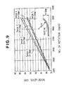
- FIG. 9 shows change in rotational noise when the curvature radius R of the airlift 44 is changed with the height H of the airlift 44 fixed (at 30 mm).
- the curvature radius R in sample 1 is 60 mm, 70 mm in sample 2, 140 mm in sample 3, 150 mm in sample 4, and 160 mm in sample 5.
- noise level linearly increases as rpm increases.
- the curvature radius R of the airlift 44 it is preferred to set the curvature radius R of the airlift 44 within 140 mm to 150 mm. That is, the curvature radius R below 140 mm causes increase in rotational noise, and the curvature radius R exceeding 150 mm prevents the airlift 44 from sufficiently swirling grass clippings upward. Setting the curvature radius R of the airlift 44 within 140 mm to 150 mm improves the discharge and conveyance of grass clippings, reducing air diversion, thereby avoiding increase in air resistance.
- the relationship in width between the protrusions 46a, 46b and 46c is defined as Ta > Tb > Tc as shown in FIG. 6.
- the present embodiment has been described with the three protrusions 46a, 46b, and 46c, but the number of protrusions is not limited to three, and may be 2, 4 or more in the present invention.
- the trailing edge of the airlift is shaped in a waveform comprising a plurality of protrusions (46a, 46b, 46c) and a plurality of depressions (49a, 49b).
- the protrusion (46a) closest to an outer end (47) where the centrifugal force is greatest during the rotation of the cutter blade (40), is greatest in width (Ta) so as to improve the discharging capability of grass clippings.
- the depressions limit negative pressure generated rotationally behind the airlift.
- a plurality of vent holes (45) formed in the airlift is arranged radially in lines.
Applications Claiming Priority (2)
| Application Number | Priority Date | Filing Date | Title |
|---|---|---|---|
| JP2001121477A JP3703734B2 (ja) | 2001-04-19 | 2001-04-19 | 芝刈機のカッタブレード |
| JP2001121477 | 2001-04-19 |
Publications (3)
| Publication Number | Publication Date |
|---|---|
| EP1260130A2 true EP1260130A2 (de) | 2002-11-27 |
| EP1260130A3 EP1260130A3 (de) | 2007-07-04 |
| EP1260130B1 EP1260130B1 (de) | 2008-07-09 |
Family
ID=18971342
Family Applications (1)
| Application Number | Title | Priority Date | Filing Date |
|---|---|---|---|
| EP02007657A Expired - Fee Related EP1260130B1 (de) | 2001-04-19 | 2002-04-04 | Rasenmähermesser |
Country Status (9)
| Country | Link |
|---|---|
| US (1) | US6655119B2 (de) |
| EP (1) | EP1260130B1 (de) |
| JP (1) | JP3703734B2 (de) |
| KR (1) | KR100542055B1 (de) |
| CN (1) | CN1240265C (de) |
| AU (1) | AU781594B2 (de) |
| CA (1) | CA2380880C (de) |
| DE (1) | DE60227449D1 (de) |
| TW (1) | TW548073B (de) |
Cited By (1)
| Publication number | Priority date | Publication date | Assignee | Title |
|---|---|---|---|---|
| EP2111737A3 (de) * | 2008-04-25 | 2010-01-06 | SABO-Maschinenfabrik GmbH | Messerbalken und Mähgerät oder Mähwerk |
Families Citing this family (57)
| Publication number | Priority date | Publication date | Assignee | Title |
|---|---|---|---|---|
| JP2006067918A (ja) * | 2004-09-02 | 2006-03-16 | Honda Motor Co Ltd | 芝刈機 |
| US20100043378A1 (en) * | 2005-04-29 | 2010-02-25 | Raymond Eric Abernethy | cutting blade assembly for a mower |
| US7617664B1 (en) * | 2005-09-09 | 2009-11-17 | Fitzpatrick Kevin E | Rotary cutting blade assembly |
| US8458998B2 (en) * | 2007-02-15 | 2013-06-11 | Wayne Arthur Smith | Rotary lawn mower cutting blade |
| ITTV20080091A1 (it) * | 2008-07-03 | 2010-01-04 | Benedetto Mauro De | Lame a molteplici ali ed alette taglienti inclinate al verso, applicabili a qualsiasi supporto rotativo, idonee al taglio dell'erba o del prato. |
| US20110203246A1 (en) * | 2010-02-19 | 2011-08-25 | Daffin Iii Charles Ernest | End weighted mower blade |
| KR200448876Y1 (ko) * | 2010-03-03 | 2010-05-28 | 김용만 | 휴대용 예초기 회전날 |
| CN101904244B (zh) * | 2010-07-09 | 2013-03-27 | 宁波大叶园林设备有限公司 | 无刀座的草坪割草机用割草刀 |
| CN101911884B (zh) * | 2010-07-15 | 2013-05-29 | 宁波大叶园林设备有限公司 | 草坪割草机用多齿割草刀 |
| US20120042765A1 (en) | 2010-08-20 | 2012-02-23 | Kazda Austin J | Reciprocating saw blade |
| CN102084753B (zh) * | 2010-11-05 | 2012-05-23 | 聂伟 | 割草机的割草刀片 |
| EP2670228A4 (de) * | 2011-02-04 | 2015-10-28 | Blount Inc | Schaufel mit schutt-luftaufzug |
| US9003754B1 (en) | 2011-06-06 | 2015-04-14 | John Robert Fogle, III | Stalk reducing bar and mower having a stalk reducing bar |
| JP5948088B2 (ja) * | 2012-02-29 | 2016-07-06 | 株式会社クボタ | 歩行型草刈機 |
| US8615977B2 (en) * | 2012-03-24 | 2013-12-31 | Anthony C. Campione | Shear and grind rotary mulching mower blade |
| ITMI20120292U1 (it) * | 2012-08-02 | 2014-02-03 | Ggp Italy Spa | Tosaerba munito di una protezione inferiore per migliorare l'efficienza di evacuazione dell'erba tagliata. |
| US9844176B2 (en) * | 2012-10-22 | 2017-12-19 | Fournier And Grande Trust | Weed trimmer extension device |
| US20150047308A1 (en) * | 2013-08-14 | 2015-02-19 | Ariens Company | Cutting blade for a lawn mower |
| US20150052868A1 (en) * | 2013-08-20 | 2015-02-26 | Ariens Company | Lawn mower including reduced turbulence cutting blades |
| JP6042299B2 (ja) * | 2013-09-20 | 2016-12-14 | 株式会社クボタ | モーアのカッターブレード |
| CN103636348A (zh) * | 2013-11-27 | 2014-03-19 | 铜陵市经纬流体科技有限公司 | 一种旋刀 |
| JP6243273B2 (ja) * | 2014-03-27 | 2017-12-06 | 本田技研工業株式会社 | 芝刈機 |
| USD766332S1 (en) * | 2015-01-02 | 2016-09-13 | Husqvarna Ab | Bagging blade |
| CA2973687C (en) | 2015-01-12 | 2019-11-12 | Husqvarna Ab | Cutting deck flow control assembly |
| USD786310S1 (en) | 2015-11-06 | 2017-05-09 | Husqvarna Ab | Mower blade |
| CN106900267A (zh) * | 2015-12-23 | 2017-06-30 | 苏州宝时得电动工具有限公司 | 打草机 |
| KR101879301B1 (ko) * | 2016-01-04 | 2018-07-17 | 강재원 | 예취기 |
| EP3195718B1 (de) * | 2016-01-23 | 2019-07-24 | Andreas Stihl AG & Co. KG | Schneidmesser für einen werkzeugkopf eines freischneiders |
| JP6654929B2 (ja) | 2016-02-29 | 2020-02-26 | 本田技研工業株式会社 | 芝刈機 |
| JP6147880B1 (ja) * | 2016-02-29 | 2017-06-14 | 本田技研工業株式会社 | 芝刈機 |
| JP6193421B2 (ja) | 2016-02-29 | 2017-09-06 | 本田技研工業株式会社 | 芝刈機 |
| JP6193419B2 (ja) * | 2016-02-29 | 2017-09-06 | 本田技研工業株式会社 | 芝刈機 |
| JP6313348B2 (ja) * | 2016-02-29 | 2018-04-18 | 本田技研工業株式会社 | 芝刈機 |
| JP6193420B2 (ja) | 2016-02-29 | 2017-09-06 | 本田技研工業株式会社 | 芝刈機 |
| JP6147881B1 (ja) | 2016-02-29 | 2017-06-14 | 本田技研工業株式会社 | 芝刈機 |
| US10117380B1 (en) | 2016-05-16 | 2018-11-06 | Board Of Trustees Of The University Of Alabama, For And On Behalf Of The University Of Alabama In Huntsville | Systems and methods for reducing cutting blade noise |
| SE539614C2 (en) * | 2016-08-25 | 2017-10-17 | Husqvarna Ab | Cutting blade and lawn mower |
| JP6802852B2 (ja) * | 2016-10-31 | 2020-12-23 | 本田技研工業株式会社 | 作業車両 |
| JP6640709B2 (ja) * | 2016-12-26 | 2020-02-05 | 本田技研工業株式会社 | 作業機 |
| JP2018102234A (ja) | 2016-12-27 | 2018-07-05 | 本田技研工業株式会社 | カッタブレード及び芝刈機 |
| JP6559114B2 (ja) * | 2016-12-27 | 2019-08-14 | 本田技研工業株式会社 | 芝刈機 |
| DE102017210945A1 (de) * | 2017-06-28 | 2019-01-03 | Deere & Company | Häckselmesser für einen Strohhäcksler |
| USD837266S1 (en) * | 2017-10-31 | 2019-01-01 | Husqvarna Ab | Lawnmower blade |
| USD837268S1 (en) * | 2017-10-31 | 2019-01-01 | Husqvarna Ab | Lawnmower blade |
| USD837267S1 (en) * | 2017-10-31 | 2019-01-01 | Husqvarna Ab | Lawnmower blade |
| EP3536139B1 (de) * | 2018-03-09 | 2021-10-13 | Techtronic Outdoor Products Technology Limited | Kantenaufsatz für einen trimmerkopf |
| WO2019195875A1 (en) * | 2018-04-11 | 2019-10-17 | Dimitrakopoulos, Elias | Improved cutting blade |
| CN108966802A (zh) * | 2018-06-25 | 2018-12-11 | 安徽豪鼎金属制品有限公司 | 一种除草刀 |
| CA3114468C (en) * | 2018-09-27 | 2022-04-12 | Nanjing Chervon Industry Co., Ltd. | Lawn mower |
| CN210610341U (zh) | 2018-09-27 | 2020-05-26 | 南京德朔实业有限公司 | 割草机和适用于割草机的刀片组件 |
| USD873302S1 (en) * | 2018-10-25 | 2020-01-21 | Husqvarna Ab | Mower blade |
| USD995569S1 (en) * | 2019-04-18 | 2023-08-15 | Nanjing Chervon Industry Co., Ltd. | Mower blade assembly |
| JP2020188712A (ja) | 2019-05-21 | 2020-11-26 | 株式会社クボタ | モーアのカッターブレード |
| USD997999S1 (en) * | 2021-05-19 | 2023-09-05 | Milwaukee Electric Tool Corporation | Attachment interface for a mower blade |
| WO2023124380A1 (zh) * | 2021-12-27 | 2023-07-06 | 南京泉峰科技有限公司 | 刀片及割草机 |
| USD1013739S1 (en) * | 2022-05-31 | 2024-02-06 | Husqvarna Ab | Lawn mower blade |
| US11917940B1 (en) | 2023-08-21 | 2024-03-05 | Dimaag-Ai, Inc. | Electric lawnmowers with cooling features integrated into mowing-unit enclosures and methods of operating thereof |
Citations (6)
| Publication number | Priority date | Publication date | Assignee | Title |
|---|---|---|---|---|
| DE2930712A1 (de) * | 1979-07-28 | 1981-02-19 | Gutbrod Werke Gmbh | Windfluegel zur erzeugung eines luftstromes |
| EP0430281A1 (de) * | 1989-12-01 | 1991-06-05 | Trinecke Zelezarny | Messerkopf für einen Rasenmäher |
| US5197268A (en) * | 1991-11-29 | 1993-03-30 | Barrera Sev | Mulching blade |
| JP2519253Y2 (ja) * | 1991-05-10 | 1996-12-04 | 本田技研工業株式会社 | 芝刈機用ロータリカッターブレード |
| DE10062461A1 (de) * | 2000-12-14 | 2002-06-20 | Sabo Maschinenfabrik Gmbh | Trenneinrichtung und Mähgerät oder Mähwerk |
| US6487840B1 (en) * | 2000-07-20 | 2002-12-03 | Fisher Barton, Inc. | Combined mulching and shredding blade |
Family Cites Families (7)
| Publication number | Priority date | Publication date | Assignee | Title |
|---|---|---|---|---|
| US3636685A (en) * | 1971-03-15 | 1972-01-25 | Tony Locono | Rotary lawnmower blade |
| US3998037A (en) * | 1975-12-18 | 1976-12-21 | Deans John N | Means for mulching leaves and the like |
| US4015408A (en) * | 1976-03-29 | 1977-04-05 | Cornellier Maurice H | Safety guard for rotary-type cutter |
| FR2421544A1 (fr) * | 1978-04-07 | 1979-11-02 | Wolf Outils | Perfectionnement au dispositif de coupe pour tondeuse a gazon du type a lames tournantes |
| IT1110904B (it) * | 1979-01-15 | 1986-01-13 | Fedeli Luisa | Lama a struttura perfezionata,applicabile a rasaerba rotativi |
| US4254607A (en) * | 1979-08-21 | 1981-03-10 | Deere & Company | Low noise producing lawn mower blade |
| EP0032967A1 (de) * | 1980-01-29 | 1981-08-05 | Black & Decker Inc. | Messer für einen Rotations-Rasenmäher |
-
2001
- 2001-04-19 JP JP2001121477A patent/JP3703734B2/ja not_active Expired - Fee Related
-
2002
- 2002-03-26 TW TW091105865A patent/TW548073B/zh not_active IP Right Cessation
- 2002-03-27 US US10/108,526 patent/US6655119B2/en not_active Expired - Lifetime
- 2002-04-04 EP EP02007657A patent/EP1260130B1/de not_active Expired - Fee Related
- 2002-04-04 DE DE60227449T patent/DE60227449D1/de not_active Expired - Lifetime
- 2002-04-08 CA CA002380880A patent/CA2380880C/en not_active Expired - Fee Related
- 2002-04-11 KR KR1020020019630A patent/KR100542055B1/ko active IP Right Grant
- 2002-04-16 AU AU34347/02A patent/AU781594B2/en not_active Ceased
- 2002-04-19 CN CNB021180296A patent/CN1240265C/zh not_active Expired - Fee Related
Patent Citations (6)
| Publication number | Priority date | Publication date | Assignee | Title |
|---|---|---|---|---|
| DE2930712A1 (de) * | 1979-07-28 | 1981-02-19 | Gutbrod Werke Gmbh | Windfluegel zur erzeugung eines luftstromes |
| EP0430281A1 (de) * | 1989-12-01 | 1991-06-05 | Trinecke Zelezarny | Messerkopf für einen Rasenmäher |
| JP2519253Y2 (ja) * | 1991-05-10 | 1996-12-04 | 本田技研工業株式会社 | 芝刈機用ロータリカッターブレード |
| US5197268A (en) * | 1991-11-29 | 1993-03-30 | Barrera Sev | Mulching blade |
| US6487840B1 (en) * | 2000-07-20 | 2002-12-03 | Fisher Barton, Inc. | Combined mulching and shredding blade |
| DE10062461A1 (de) * | 2000-12-14 | 2002-06-20 | Sabo Maschinenfabrik Gmbh | Trenneinrichtung und Mähgerät oder Mähwerk |
Cited By (1)
| Publication number | Priority date | Publication date | Assignee | Title |
|---|---|---|---|---|
| EP2111737A3 (de) * | 2008-04-25 | 2010-01-06 | SABO-Maschinenfabrik GmbH | Messerbalken und Mähgerät oder Mähwerk |
Also Published As
| Publication number | Publication date |
|---|---|
| US20020152736A1 (en) | 2002-10-24 |
| CA2380880C (en) | 2005-08-09 |
| CN1240265C (zh) | 2006-02-08 |
| US6655119B2 (en) | 2003-12-02 |
| DE60227449D1 (de) | 2008-08-21 |
| AU3434702A (en) | 2002-10-24 |
| KR100542055B1 (ko) | 2006-01-16 |
| AU781594B2 (en) | 2005-06-02 |
| EP1260130A3 (de) | 2007-07-04 |
| JP2002315418A (ja) | 2002-10-29 |
| CA2380880A1 (en) | 2002-10-19 |
| CN1381164A (zh) | 2002-11-27 |
| EP1260130B1 (de) | 2008-07-09 |
| KR20020082107A (ko) | 2002-10-30 |
| JP3703734B2 (ja) | 2005-10-05 |
| TW548073B (en) | 2003-08-21 |
Similar Documents
| Publication | Publication Date | Title |
|---|---|---|
| US6655119B2 (en) | Cutter blade for lawn mower | |
| AU667910B2 (en) | A cutter | |
| US7065946B2 (en) | Lawnmower having mulching cutter deck assembly | |
| CA1090147A (en) | Grass mower | |
| US5363635A (en) | Mulching mower with improved mulching blade | |
| GB2037138A (en) | Rotary mower | |
| EP1360888B1 (de) | Mähmesser | |
| US4426831A (en) | Mower blade | |
| EP0300642A1 (de) | Rasenmäher mit rotierendem Messer | |
| CA2159803A1 (en) | Radial impeller | |
| US4328661A (en) | Cross flow rotary mower having an axial expansion section | |
| US6594981B2 (en) | Mowing and mulching system for lawnmowers | |
| EP0738463A1 (de) | Rasenmäher mit einem Gehäuse mit Bypassgebläse | |
| WO1991001586A1 (en) | A fan for an electrically operated machine | |
| GB2215176A (en) | Lawnmower | |
| GB2242813A (en) | Cylinder lawnmowers | |
| JPH0323054Y2 (de) | ||
| JP2584133B2 (ja) | 草芝刈り用カッターブレード | |
| CA1164665A (en) | Quiet serrated lawn mower blade | |
| GB2411567A (en) | Lawnmower blade | |
| JPH04127119U (ja) | 芝刈機用ロータリカツターブレード | |
| JPH0518903Y2 (de) | ||
| AU684123B2 (en) | Cutter assembly for lawn mowers | |
| EP1048193A1 (de) | Rotierbarer Vertikutierer | |
| WO2008033070A1 (en) | Cylinder lawn mower |
Legal Events
| Date | Code | Title | Description |
|---|---|---|---|
| PUAI | Public reference made under article 153(3) epc to a published international application that has entered the european phase |
Free format text: ORIGINAL CODE: 0009012 |
|
| AK | Designated contracting states |
Kind code of ref document: A2 Designated state(s): AT BE CH CY DE DK ES FI FR GB GR IE IT LI LU MC NL PT SE TR |
|
| AX | Request for extension of the european patent |
Free format text: AL;LT;LV;MK;RO;SI |
|
| PUAL | Search report despatched |
Free format text: ORIGINAL CODE: 0009013 |
|
| AK | Designated contracting states |
Kind code of ref document: A3 Designated state(s): AT BE CH CY DE DK ES FI FR GB GR IE IT LI LU MC NL PT SE TR |
|
| AX | Request for extension of the european patent |
Extension state: AL LT LV MK RO SI |
|
| 17P | Request for examination filed |
Effective date: 20071108 |
|
| GRAP | Despatch of communication of intention to grant a patent |
Free format text: ORIGINAL CODE: EPIDOSNIGR1 |
|
| AKX | Designation fees paid |
Designated state(s): DE FR GB IT |
|
| GRAS | Grant fee paid |
Free format text: ORIGINAL CODE: EPIDOSNIGR3 |
|
| GRAA | (expected) grant |
Free format text: ORIGINAL CODE: 0009210 |
|
| AK | Designated contracting states |
Kind code of ref document: B1 Designated state(s): DE FR GB IT |
|
| REG | Reference to a national code |
Ref country code: GB Ref legal event code: FG4D |
|
| REF | Corresponds to: |
Ref document number: 60227449 Country of ref document: DE Date of ref document: 20080821 Kind code of ref document: P |
|
| PLBE | No opposition filed within time limit |
Free format text: ORIGINAL CODE: 0009261 |
|
| STAA | Information on the status of an ep patent application or granted ep patent |
Free format text: STATUS: NO OPPOSITION FILED WITHIN TIME LIMIT |
|
| 26N | No opposition filed |
Effective date: 20090414 |
|
| REG | Reference to a national code |
Ref country code: FR Ref legal event code: PLFP Year of fee payment: 15 |
|
| REG | Reference to a national code |
Ref country code: FR Ref legal event code: PLFP Year of fee payment: 16 |
|
| REG | Reference to a national code |
Ref country code: FR Ref legal event code: PLFP Year of fee payment: 17 |
|
| PGFP | Annual fee paid to national office [announced via postgrant information from national office to epo] |
Ref country code: NL Payment date: 20190313 Year of fee payment: 16 |
|
| REG | Reference to a national code |
Ref country code: DE Ref legal event code: R084 Ref document number: 60227449 Country of ref document: DE |
|
| REG | Reference to a national code |
Ref country code: GB Ref legal event code: 746 Effective date: 20191212 |
|
| PGFP | Annual fee paid to national office [announced via postgrant information from national office to epo] |
Ref country code: GB Payment date: 20200325 Year of fee payment: 19 |
|
| PGFP | Annual fee paid to national office [announced via postgrant information from national office to epo] |
Ref country code: FR Payment date: 20200312 Year of fee payment: 19 |
|
| PGFP | Annual fee paid to national office [announced via postgrant information from national office to epo] |
Ref country code: DE Payment date: 20200325 Year of fee payment: 19 |
|
| PG25 | Lapsed in a contracting state [announced via postgrant information from national office to epo] |
Ref country code: IT Free format text: LAPSE BECAUSE OF NON-PAYMENT OF DUE FEES Effective date: 20200404 |
|
| REG | Reference to a national code |
Ref country code: DE Ref legal event code: R119 Ref document number: 60227449 Country of ref document: DE |
|
| GBPC | Gb: european patent ceased through non-payment of renewal fee |
Effective date: 20210404 |
|
| PG25 | Lapsed in a contracting state [announced via postgrant information from national office to epo] |
Ref country code: GB Free format text: LAPSE BECAUSE OF NON-PAYMENT OF DUE FEES Effective date: 20210404 Ref country code: FR Free format text: LAPSE BECAUSE OF NON-PAYMENT OF DUE FEES Effective date: 20210430 Ref country code: DE Free format text: LAPSE BECAUSE OF NON-PAYMENT OF DUE FEES Effective date: 20211103 |