EP1259185B1 - Verfahren zum navigieren im körperinneren anhand dreidimensional visualisierter strukturen - Google Patents
Verfahren zum navigieren im körperinneren anhand dreidimensional visualisierter strukturen Download PDFInfo
- Publication number
- EP1259185B1 EP1259185B1 EP01971825A EP01971825A EP1259185B1 EP 1259185 B1 EP1259185 B1 EP 1259185B1 EP 01971825 A EP01971825 A EP 01971825A EP 01971825 A EP01971825 A EP 01971825A EP 1259185 B1 EP1259185 B1 EP 1259185B1
- Authority
- EP
- European Patent Office
- Prior art keywords
- determined
- dimensional
- visualized
- spatial
- geometrical structure
- Prior art date
- Legal status (The legal status is an assumption and is not a legal conclusion. Google has not performed a legal analysis and makes no representation as to the accuracy of the status listed.)
- Expired - Lifetime
Links
Images




Classifications
-
- G—PHYSICS
- G06—COMPUTING OR CALCULATING; COUNTING
- G06T—IMAGE DATA PROCESSING OR GENERATION, IN GENERAL
- G06T19/00—Manipulating three-dimensional [3D] models or images for computer graphics
- G06T19/003—Navigation within 3D models or images
-
- A—HUMAN NECESSITIES
- A61—MEDICAL OR VETERINARY SCIENCE; HYGIENE
- A61B—DIAGNOSIS; SURGERY; IDENTIFICATION
- A61B34/00—Computer-aided surgery; Manipulators or robots specially adapted for use in surgery
- A61B34/20—Surgical navigation systems; Devices for tracking or guiding surgical instruments, e.g. for frameless stereotaxis
-
- A—HUMAN NECESSITIES
- A61—MEDICAL OR VETERINARY SCIENCE; HYGIENE
- A61B—DIAGNOSIS; SURGERY; IDENTIFICATION
- A61B90/00—Instruments, implements or accessories specially adapted for surgery or diagnosis and not covered by any of the groups A61B1/00 - A61B50/00, e.g. for luxation treatment or for protecting wound edges
- A61B90/36—Image-producing devices or illumination devices not otherwise provided for
-
- G—PHYSICS
- G06—COMPUTING OR CALCULATING; COUNTING
- G06T—IMAGE DATA PROCESSING OR GENERATION, IN GENERAL
- G06T15/00—Three-dimensional [3D] image rendering
- G06T15/10—Geometric effects
- G06T15/20—Perspective computation
-
- G—PHYSICS
- G06—COMPUTING OR CALCULATING; COUNTING
- G06T—IMAGE DATA PROCESSING OR GENERATION, IN GENERAL
- G06T7/00—Image analysis
- G06T7/50—Depth or shape recovery
- G06T7/55—Depth or shape recovery from multiple images
- G06T7/564—Depth or shape recovery from multiple images from contours
-
- G—PHYSICS
- G06—COMPUTING OR CALCULATING; COUNTING
- G06T—IMAGE DATA PROCESSING OR GENERATION, IN GENERAL
- G06T7/00—Image analysis
- G06T7/50—Depth or shape recovery
- G06T7/55—Depth or shape recovery from multiple images
- G06T7/593—Depth or shape recovery from multiple images from stereo images
-
- A—HUMAN NECESSITIES
- A61—MEDICAL OR VETERINARY SCIENCE; HYGIENE
- A61B—DIAGNOSIS; SURGERY; IDENTIFICATION
- A61B34/00—Computer-aided surgery; Manipulators or robots specially adapted for use in surgery
- A61B34/10—Computer-aided planning, simulation or modelling of surgical operations
- A61B2034/101—Computer-aided simulation of surgical operations
- A61B2034/105—Modelling of the patient, e.g. for ligaments or bones
-
- A—HUMAN NECESSITIES
- A61—MEDICAL OR VETERINARY SCIENCE; HYGIENE
- A61B—DIAGNOSIS; SURGERY; IDENTIFICATION
- A61B34/00—Computer-aided surgery; Manipulators or robots specially adapted for use in surgery
- A61B34/10—Computer-aided planning, simulation or modelling of surgical operations
- A61B2034/107—Visualisation of planned trajectories or target regions
-
- A—HUMAN NECESSITIES
- A61—MEDICAL OR VETERINARY SCIENCE; HYGIENE
- A61B—DIAGNOSIS; SURGERY; IDENTIFICATION
- A61B34/00—Computer-aided surgery; Manipulators or robots specially adapted for use in surgery
- A61B34/20—Surgical navigation systems; Devices for tracking or guiding surgical instruments, e.g. for frameless stereotaxis
- A61B2034/2046—Tracking techniques
- A61B2034/2055—Optical tracking systems
-
- A—HUMAN NECESSITIES
- A61—MEDICAL OR VETERINARY SCIENCE; HYGIENE
- A61B—DIAGNOSIS; SURGERY; IDENTIFICATION
- A61B34/00—Computer-aided surgery; Manipulators or robots specially adapted for use in surgery
- A61B34/20—Surgical navigation systems; Devices for tracking or guiding surgical instruments, e.g. for frameless stereotaxis
- A61B2034/2068—Surgical navigation systems; Devices for tracking or guiding surgical instruments, e.g. for frameless stereotaxis using pointers, e.g. pointers having reference marks for determining coordinates of body points
-
- A—HUMAN NECESSITIES
- A61—MEDICAL OR VETERINARY SCIENCE; HYGIENE
- A61B—DIAGNOSIS; SURGERY; IDENTIFICATION
- A61B90/00—Instruments, implements or accessories specially adapted for surgery or diagnosis and not covered by any of the groups A61B1/00 - A61B50/00, e.g. for luxation treatment or for protecting wound edges
- A61B90/36—Image-producing devices or illumination devices not otherwise provided for
- A61B2090/364—Correlation of different images or relation of image positions in respect to the body
-
- A—HUMAN NECESSITIES
- A61—MEDICAL OR VETERINARY SCIENCE; HYGIENE
- A61B—DIAGNOSIS; SURGERY; IDENTIFICATION
- A61B90/00—Instruments, implements or accessories specially adapted for surgery or diagnosis and not covered by any of the groups A61B1/00 - A61B50/00, e.g. for luxation treatment or for protecting wound edges
- A61B90/36—Image-producing devices or illumination devices not otherwise provided for
- A61B2090/364—Correlation of different images or relation of image positions in respect to the body
- A61B2090/367—Correlation of different images or relation of image positions in respect to the body creating a 3D dataset from 2D images using position information
-
- A—HUMAN NECESSITIES
- A61—MEDICAL OR VETERINARY SCIENCE; HYGIENE
- A61B—DIAGNOSIS; SURGERY; IDENTIFICATION
- A61B34/00—Computer-aided surgery; Manipulators or robots specially adapted for use in surgery
- A61B34/10—Computer-aided planning, simulation or modelling of surgical operations
-
- A—HUMAN NECESSITIES
- A61—MEDICAL OR VETERINARY SCIENCE; HYGIENE
- A61B—DIAGNOSIS; SURGERY; IDENTIFICATION
- A61B34/00—Computer-aided surgery; Manipulators or robots specially adapted for use in surgery
- A61B34/25—User interfaces for surgical systems
-
- G—PHYSICS
- G06—COMPUTING OR CALCULATING; COUNTING
- G06T—IMAGE DATA PROCESSING OR GENERATION, IN GENERAL
- G06T2207/00—Indexing scheme for image analysis or image enhancement
- G06T2207/10—Image acquisition modality
- G06T2207/10072—Tomographic images
- G06T2207/10088—Magnetic resonance imaging [MRI]
-
- G—PHYSICS
- G06—COMPUTING OR CALCULATING; COUNTING
- G06T—IMAGE DATA PROCESSING OR GENERATION, IN GENERAL
- G06T2207/00—Indexing scheme for image analysis or image enhancement
- G06T2207/10—Image acquisition modality
- G06T2207/10072—Tomographic images
- G06T2207/10112—Digital tomosynthesis [DTS]
-
- G—PHYSICS
- G06—COMPUTING OR CALCULATING; COUNTING
- G06T—IMAGE DATA PROCESSING OR GENERATION, IN GENERAL
- G06T2207/00—Indexing scheme for image analysis or image enhancement
- G06T2207/30—Subject of image; Context of image processing
- G06T2207/30004—Biomedical image processing
- G06T2207/30008—Bone
-
- G—PHYSICS
- G06—COMPUTING OR CALCULATING; COUNTING
- G06T—IMAGE DATA PROCESSING OR GENERATION, IN GENERAL
- G06T2210/00—Indexing scheme for image generation or computer graphics
- G06T2210/41—Medical
Definitions
- the invention relates to a computer-aided navigation aid for navigating, for example, a surgical instrument or an endoscope in the interior of the body on the basis of three-dimensionally visualized structures.
- Such three-dimensional representations can be generated, for example, by means of computed tomography (CT).
- CT procedures are used primarily for obtaining preoperative data due to the circumstances of the apparatus and the high computational complexity.
- intraoperative i. during visualization visualization CT techniques are therefore not suitable.
- high radiation exposure associated with CT procedures is undesirable for the patient.
- the US 5,852,646 describes a method in which a three-dimensional representation of the object is calculated from a series of images from different perspectives, which is then output on a two-dimensional display. Such a representation no longer refers directly to the images used, but to the object generated by calculation or to an extracted geometric attribute (point, line, etc.).
- the invention has for its object to provide a system and a preoperative method for computer-aided generating a navigation aid using three-dimensional visualized structures inside the body, which avoids high radiation exposure of the patient, is associated with little computational effort and is therefore particularly suitable for intraoperative use.
- this object is achieved in that, in a first step, at least two two-dimensional images of the same anatomical object from different recording positions as well as information about the respective spatial position of the recording system relative to the anatomical object are provided. In a second step, a projection of a geometric structure to be visualized is subsequently defined in each of the two-dimensional images, wherein the geometric image to be visualized is to be visualized Structure different from the anatomical object and from two recordings can be determined auratig.
- a conical surface is generated in space for each of the images, wherein the spatial position of the conical tip and the conical curve are determined from the spatial position of the recording system and the shape of the conical curve from the fixed projection of the geometric structure to be visualized on the respective image.
- the spatial section of the individual conical surfaces is formed, this spatial section corresponding to the geometric structure to be visualized in the interior of the body. Subsequently, the geometric structure thus determined or a section of a plurality of geometrical structures determined in this way or both the structures and their section are graphically represented as navigation aid.
- anatomical object or an e. G. surgical instrument, or both, graphically represented in three dimensions.
- the three-dimensional representation of the anatomical object and the surgical instrument can be obtained in the same or similar manner as the three-dimensional representation of the geometric structure.
- a three-dimensional model of the geometric structure to be visualized is created from projections defined on a few two-dimensional images. Since in the simplest case only two two-dimensional images must be present, and these two images need not necessarily be created with an imaging method using X-rays or other high-energy radiation, in the visualization method according to the invention, the radiation exposure for the patient compared to conventional CT Procedure negligible. As well as the amount of data to be processed In particular, compared to CT procedures are relatively low, the visualization can be performed extremely quickly and even intraoperatively to provide the surgeon up-to-date information about the course of the operation. Furthermore, the radiation exposure for the surgical team can be significantly reduced.
- the setting of the projections on the recordings can be done in different ways, for example, automatically, semi-automatically or manually.
- the setting takes place in such a way that, after setting, information relating to the specified projections is available as digital data and can be further processed for the purpose of visualization using computer-aided processing.
- the shape of the geometric structure to be visualized is determined at the same time.
- the projection to be defined in a particular shot may be, for example, a point, a line, a circle segment, or any other line-like structure.
- the geometric structure to be visualized may be any one-dimensional, two-dimensional or three-dimensional structure such as a point, a straight line, a plane or a sphere.
- the geometric structure to be visualized does not coincide with the anatomical object depicted on the two-dimensional image, but may be derived therefrom.
- the determination of information that allows conclusions about the spatial locations of the recording system in which the recording was taken can be done in many ways.
- the spatial position of the recording system immutable and, as a rule, be known in advance, and the position of the anatomical object from recording to recording are changed. From the respective position of the anatomical object can then be calculated back to the respective fictitious recording positions, assuming a stationary, anatomical object.
- the anatomical object stationary in the room and to change the spatial position of the recording system from recording to recording.
- a tracking system known from the prior art.
- a marker for a room-installed infrared tracking system may be attached to the C-arm.
- the exact spatial position of the C-arm which allows a conclusion on the spatial positions of an X-ray source and an X-ray detector, can then be determined via the tracking system. Due to the spatial position of the X-ray source and the X-ray detector, the spatial position of the conical surface is determined.
- the location of the C-arm can be determined by using a stationary robot. The robot moves a calibrated object with radiopaque marks into the beam path of the C-arm. The position of the C-arm can be calculated from the position of the marks in the picture.
- the individual two-dimensional images can be created in different ways.
- the spatial positions of the cone tip and the cone-shaped curve are determined in different ways.
- the anatomical object, and possibly also the surgical instrument is arranged between an X-ray source and an X-ray detector.
- the spatial position of the X-ray source corresponds to the spatial position of the apex of the cone and the spatial position of the X-ray detector to the spatial position of the cone-shaped curve.
- the characteristic data of the X-ray optics can be used to calculate the spatial positions of the cone tip and the cone-side curve.
- the two-dimensional images were created by other imaging methods than X-ray methods (infrared methods, ultrasound methods, MR methods, etc.), it is usually necessary to additionally determine the respective system parameters of the recording system in determining the spatial positions of Cone tip and Kegelelleitkurve to consider.
- a conical surface is generated in the room for each two-dimensional recording.
- a conic surface is created by moving a straight line passing through a fixed point, the cone apex, along a curve, the conical curve.
- the tapered curve thus determines the shape of the conical surface.
- the Kegelelleitkurve can be a straight line, which is set as the surgeon targeted preferred direction in each shot.
- the preferred direction can identify the direction from which, for example, an endoscope or a surgical instrument is to approach an anatomical object to be treated.
- the Kegelleitkurve is a straight line, the associated conical surface has a triangular shape.
- the Kegelelleitkurve may also be a point, which is set, for example, as a target position in each of the shots. This target position may indicate a location at which surgery is to take place.
- the associated conical surface In a punctiform cone-shaped curve, the associated conical surface has the shape of a straight line.
- a preferred direction to be visualized or a sphere to be visualized can be detected by means of two images, i. be defined exactly and clearly by means of the intersection of two cones.
- At least one further data set which was created preoperatively or intraoperatively, is used for refining correction, e.g. an approximation model of an anatomical object used.
- This further data record may be a data record which was created by a magnetoresonance method (MR method).
- MR tomography has the advantage that it is not associated with any radiation exposure to the patient.
- a three-dimensional representation of an anatomical object that has been generated from two-dimensional x-ray images can be refined by means of one or more MR images.
- a projection of a surface or an outline of the bone cancellous bone in each two-dimensional X-ray image can be determined and for each X-ray recording a conical surface generated in space, the spatial positions of the apex and Kegelelleitkurve from the respective spatial position of the recording system and the shape of the cone-line curve can be determined from the shape of the projection.
- a spatial section of the individual conical surfaces can be formed and from the MR data set a second model of cancellous bone can be determined.
- a representation of the bone can then be generated by combining the two models, whereby the representation can be used to navigate, for example.
- the first three-dimensional model can also be determined in other ways than explained above.
- a correction of the geometric structure resulting from the spatial intersection of the conical surfaces or of an approximation model of the anatomical object can also be effected by means of such a data set which contains a generic, shape-variable model of the structure or of the object.
- a generic model can, for example, be derived from anatomical atlases or be obtained from an exact model of a patient comparable according to age, sex, origin, etc.
- an inverse calculation is made in order to obtain suitable spatial positions of the recording system for further two-dimensional recordings for improving the representation to investigate.
- the surgeon can record directions for the C-arm of an X-ray recording system are displayed, from which a fluoroscopy based on the previous calculations seems reasonable.
- the current position of an instrument to be navigated can be displayed simultaneously.
- the position of the instrument relative to the anatomical structure to be treated can be determined in different ways.
- the marker of a tracking system can be attached to the instrument and the current position of the instrument can be determined with the aid of the tracking system.
- the effective axis of the instrument is also shown apart from the instrument. The axis of action gives e.g. the direction in which a surgical instrument is used.
- the individual two-dimensional images on which the visualization of the geometric structure is based can also be graphically displayed at the same time.
- the individual two-dimensional images can be arranged in the representation such that their spatial position in the graphic representation corresponds to their respective recording position.
- a navigation aid for the instrument can be depicted in the above-described graphical representation of the geometric structure to be visualized or in a separate representation.
- the navigation aid shows e.g. the current position of the axis of action of the surgical instrument relative to a visualizing preferential direction in the form of a tunnel structure.
- the navigation aid may further comprise directional arrows, which facilitate the alignment of the axis of action along the preferred direction.
- FIG. 1 schematically shows an operation scenario based on the preoperative method according to the invention.
- an operatively treated anatomical object in the form of a femur 12 is arranged on an operating table 10 .
- the surgery is performed with the aid of a surgical instrument 14.
- Attached to the surgical instrument 14 is a marker 16 of an infrared tracking system.
- This marker 16 is designed to transmit infrared radiation.
- the infrared tracking system further comprises a stationary infrared detector 18.
- a localization computer 20 of the tracking system calculates from the signals received from the infrared detector 12, the current spatial position of the provided with the marker 16 surgical instrument 14.
- the calculated spatial coordinates from the localization computer 20 via a data bus to a central computer 22, there graphically processed and displayed on a screen 24 graphically.
- FIG. 1 furthermore shows an X-ray recording system 26 with a C-arm 28. At one of the two ends of the C-arm 28, an X-ray source 30 and at the opposite end of the C-arm 28, an X-ray detector 32 is arranged.
- the two-dimensional images produced by the X-ray recording system 26 are supplied via a data bus to the central computer 22 in digitized form. At the same time, the central computer 22 also serves to control the X-ray recording system 26.
- the spatial position of the recording position is predetermined by the spatial position of the X-ray source 30 and the spatial position of the image plane by the spatial position of the X-ray detector 32.
- a further marker 34 is attached to the C-arm 28 of the X-ray recording system 26, the structure of which matches the structure of the marker 16 arranged on the surgical instrument 14.
- the infrared detector 18 of the infrared tracking system can thus be determined in addition to the spatial position of the surgical instrument 14 and the spatial position of the recording position and the image plane.
- the relevant information is also provided via the localization computer 20 to the central computer 22.
- the central computer 22 generates a three-dimensional approximation model of the femur bone 12 from the preoperatively obtained two-dimensional images and displays this approximation model, a geometric structure to be visualized and the relative position of the surgical instrument 14 to the femur bone 12 or to the geometric structure on the screen 24.
- a conical surface 40 is shown. This conical surface 40 is formed by movement of a straight line 42 which extends through the apex 46, along the Kegelelleitkurve 44. The conical surface extends from the apex 46 along the line 42 to infinity and includes the guide curve 44 with a.
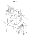
- FIG. 3 shows two conical surfaces 40 and 40 'in their relative spatial arrangement to one another. Also shown in FIG. 3 are two two-dimensional images 50, 50 'taken by the X-ray imaging system 26 shown in FIG.
- the spatial positions of the conical tips 46, 46 'of the two cones 40, 40' are determined by the spatial positions of the X-ray source for the respective recording time of the two recordings 50, 50 '.
- the shape of each Kegelelleitkurve 44, 44 ' is determined by the respective outline of the femoral bone exemplified in the receptacles 50, 50'.
- the two receptacles 50, 50 ' are arranged in that spatial position in which the respective image plane was located.
- the approximation model 52 of the femur bone is still comparatively coarse.
- a refinement of the model 52 can be carried out by taking further recordings of the femur bone 12 from additional acquisition positions in addition to the two receptacles 50, 50 'and subsequently determining the approximation model on the basis of the spatial section of three or more conical surfaces.
- Another way to improve the approximation model 52 is to consider a preoperatively determined MR data set of the femur bone shown in FIG. 1 when creating the approximation model 52. Also namely, with the help of MR tomography, a three-dimensional model of the femur 12 can be calculated.
- a typical bone is composed of a soft core tissue (cancellous bone), which is enveloped by a thin layer of harder tissue (cortical bone).
- the thickness of the cortical layer is variable.
- the cortical layer is very difficult to automatically segment.
- both the edge of the cortical layer, as well as the underlying edge of cancellous bone in the radiograph is visible.
- a fundamental problem in MR tomography is therefore that only the cancellous bone of the femur bone is clearly visible, while the outer cortical layer appears black.
- the three-dimensional model obtainable from the MR data set thus does not match the actual shape of the femur bone 12, since the outer cortical layer is missing. Nevertheless, the MR model allows conclusions to be drawn about the shape of the femur, which can be used to refine the approximation model 52 shown in FIG.
- the procedure can be as follows: The edge of the cancellous bone is marked in the X-ray images, and it is automatically segmented the surface of the cancellous bone in the magnetic resonance image. Subsequently, for the registration step (spatial adjustment of the position of the nuclear spin image to X-ray images), a method for covering the two last structures (2D X-ray contours and 3D nuclear spin surface, in each case at the cancellous bone) can be used. Thus, the actual bone surface (with cortical layer) can be visualized and act as a basis for the navigation.
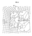
- FIG. 4 shows a two-dimensional section through the spatial arrangement shown in FIG.
- the sectional plane shown in Fig. 4 includes the two cone tips 46, 46 'and two straight lines 54, 56 which define the conical surface 40, and two straight lines 54', 56 ', which limit the conical surface 40'.
- the intersection of these four boundary lines 54, 56, 54 ', 56' determines the cross-section of the proximity model 52 that extends through the plane shown in FIG.
- FIG. 4 also shows the actual, circular cross-section of the femur bone 12. Consequently, FIG. 4 shows the deviation of the cross section of the approximation model 52 from the actual cross section of the femur bone 12. As can be seen from Fig. 4, the deviation of the approximate model 52 from the actual shape of the femur 12 is particularly strong where the delineation lines 54, 56, 54 ', 56' intersect. This insight can be used to optimize the shooting positions with respect to the location of the planned surgical procedure.
- FIG. 5 schematically shows a possibility of an intraoperative graphical representation of the approximation model 52 determined according to the above-described visualization method on the screen 24 shown in FIG. 1.
- the current position of the surgical instrument 14 relative to the approximation model 52 is also graphically represented.
- the current position of the surgical instrument 14 is determined as explained above with the aid of the infrared tracking system shown in FIG.
- a previously stored CAD data set is used.
- three two-dimensional images 50, 50 ', 50 "of the femur 12 are also displayed on the screen 24. These images 50, 50', 50" were recorded using the X-ray image shown in FIG. Recording system 26 created. They are represented on the screen 24 with respect to the approximation model 52 in the spatial position in which the x-ray detector 32 was located when making the respective receptacle 50, 50 ', 50 "relative to the femur bone 12. This makes it easier for the surgeon to navigate the surgical instrument 14 In the receptacles 50, 50 ', 50 ", the respective projection 60, 60', 60" of the effective axis of the surgical instrument 14 is furthermore shown.
- FIG. 6 shows a further possibility for the intraoperative graphical representation of the course of an operation in the form of a screen printout.
- FIG. 6 does not show a three-dimensional approximation model of the entire femur bone, but merely a three-dimensional approximation model 64 of a tumor which has infested the femur bone .
- the three-dimensional proximity model 64 of the tumor is based on four two-dimensional images 50, 50 ', 50' ', 50 "' of the femur, and the four images 50, 50 ', 50", 50' "are arranged in such a way that they represent the represent respective position of the X-ray detector 32 relative to the femur bone 12 of FIG. 1, in which the respective recording 50, 50 ', 50 ", 50' '' were created.
- Each of the four receptacles 50, 50 ', 50 “, 50”' includes a graphical representation 62, 62 ', 62 ", 62"' of the tumor. Based on the outlines of the four representations 62, 62 ', 62 ", 62 As explained with reference to FIG. 3, four conical surfaces were generated, their spatial section corresponds to the three-dimensional approximation model 64 of the tumor.
- two projections 66, 66 'of the proximity model 64 are furthermore shown, which additionally facilitate the monitoring of the surgical intervention by the surgeon.
- the spatial position of the surgical instrument 14 relative to the approximation model 64 is sketched in FIG. 6.
- the corresponding projection of the active axis 60, 60 ', 60 ", 60"' of the surgical instrument 14 is sketched. This graphic measure also helps the surgeon to monitor the surgical procedure intraoperatively.
- FIG. 6 While the removal of a tumor is outlined in FIG. 6, surgical intervention of a bore in the spherical head 70 of the femur 12 will be described below with reference to FIG. 7 with reference to a geometric navigation structure.
- the problem with such a bore is that the surgical instrument, namely the drill 14 shown in FIG. 7, should only be inserted into the femur bone 12 up to a certain penetration depth, since the drill 14 has a cartilaginous layer on the surface of the spherical head 70 of the femur bone 12 must not pierce.
- the drill 14, which is to be inserted into the femur bone 12 at the position 72, must therefore not penetrate into the femur bone 12 so far that it reaches the puncture point 74.
- cartilaginous layer on the spherical head 70 of the femur bone 12 is visible in X-ray images 50, 50 'according to FIG. 8, it can not be decided from individual two-dimensional X-ray images whether a drill has already pierced the cartilage layer. This is because an X-ray image provides only a projection of the head 70 of the femur 12, which is generally the same circular edge of the head 70 makes it appear larger than it actually is.
- the method according to the invention now enables a safe navigation of the drill 14 such that the head 70, 70' of the femur bone 12 is not pierced.
- a preferred direction 76, 76' is marked, in which the drill 14 is intended to penetrate into the head 70 of the femur bone 12.
- each of the semi-circular outline 78, 78 'of the head 70, 70' is marked manually or via a software for contour extraction. In this way, the projections of the geometric structures to be visualized are defined.
- FIG. 9 shows how the preferred direction 76, 76 'as well as a sphere corresponding to the surface of the head 70 of the femur bone 12 can be visualized three-dimensionally on the basis of the two receptacles 50, 50' according to the invention. This visualization proceeds accordingly as described above with reference to FIGS. 3 and 4.
- a spatial straight line 82 which corresponds to this preferred direction, is determined from the two receptacles 50, 50 'on the basis of the respectively indicated preferred direction 76, 76'. Since the preferred direction 76, 76 'marked in the receptacles 50, 50' is in each case a straight line piece, the two corresponding conical surfaces 40, 40 'are in the form of a flat triangle. As can be seen from FIG. 9, the spatial straight line 82 results from the spatial section of the two planes defined by the conical surfaces 40, 40 '. As a result of the intersection of the two triangular surfaces, the straight line 82, ie the preferred direction, is clearly and precisely defined.
- the spatial line 82 may be used intraoperatively to navigate the drill 14. This process will be further described below with reference to FIGS. 10 to 12.
- the spatial intersection of those conical surfaces is determined which respectively correspond to the semicircular outline 78, 78 'of the head 70 of the femur bone 12 on the receptacles 50, 50'.
- the spatial section of the conical surfaces corresponding to the semicircular contours 78, 78 ' is a visualized structure in the form of a spatial sphere 80.
- the position and shape of the sphere 80 are based on the semicircles (resp the corresponding full circle) 78, 78 'can be clearly and accurately determined.
- a section of the ball 80 with the spatial line 82 gives the spatial position of the puncture point 74th
- intraoperative visualization of the current position of the drill 14 relative to the piercing point 74 it is therefore possible to navigate the drill 14 such that in good time before reaching the piercing point 74, the drilling operation can be interrupted.
- visualization of the spatial line 82 allows for safe navigation of the drill 14.
- the distance between the tip of the drill 14 and the point of penetration 74 e.g. displayed in numerical form. If the distance is below a minimum distance, an additional acoustic warning signal sounds.
- the spatial line 82 and the ball 80 of FIG. 9 may also be represented in the three-dimensional graphs of FIGS. 5 and 6 to facilitate navigation of the surgical element 14.
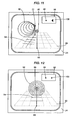
- FIGS. 10 to 12 a graphic navigation aid according to the invention for a surgical instrument will be explained by way of example for the surgical procedure illustrated in FIGS. 7 to 9.
- a graphical navigation aid is shown on the screen 24 shown in FIG.
- This navigation aid includes a crosshair 86 which marks the tip of the drill 14 shown in FIG.
- the point 88 denotes a projection of the tip of the drill 14 on a horizontal plane 90.
- the point 72 on the screen 24 indicates the desired entry point of the drill 14 in the femur bone 12.
- a tunnel-like structure 92 serves as an indication of the relative position of the spatial line 82 relative to the effective axis of the drill 14. This axis of action extends at right angles from the position of the crosshairs 86 out of the plane of the drawing.
- a projection 94 of the geometric straight line 82 can be seen.
- a direction indicator 96 is shown on the screen 24, top right.
- This direction indicator 96 indicates in which direction the tip of the drill 14 is to be moved in order to align the drill 14 along the geometric straight line 82 symbolized by the tunnel 92.
- the drill 14 In the case illustrated in FIG. 10, the drill 14 must be moved slightly downwards and relatively far to the left. This results from a small, downwardly pointing arrow in the display panel 98 and a large, pointing to the left arrow in the display 100.
- Fig. 11 the case is shown that the drill 14 has been moved from the position shown in Fig. 10 slightly down and slightly to the left. As indicated by the dot in the display panel 98, the tip of the drill 14 symbolized by the cross hair 86 is now in the same horizontal plane as the spatial straight line 82, which corresponds to the tunnel structure 92. However, as is illustrated by the small, left-facing arrow in the display panel 100, the drill 14 still has to be moved slightly to the left to align the axis of action of the drill 14 along the symbolized by the tunnel 92 geometric line 82.
- the direction display 96 now shows two points. This illustration indicates that the axis of action of the drill 14 is aligned along the preferred direction indicated by the tunnel structure 92.
- the surgeon can now switch the screen 24 in another display mode, which, for example, according to the screen print of FIG. 6 to select a three-dimensional visualization of a surgically treated structure.
Landscapes
- Engineering & Computer Science (AREA)
- Health & Medical Sciences (AREA)
- Physics & Mathematics (AREA)
- Theoretical Computer Science (AREA)
- Surgery (AREA)
- General Physics & Mathematics (AREA)
- Life Sciences & Earth Sciences (AREA)
- Public Health (AREA)
- Computer Graphics (AREA)
- Software Systems (AREA)
- Veterinary Medicine (AREA)
- Heart & Thoracic Surgery (AREA)
- General Health & Medical Sciences (AREA)
- Nuclear Medicine, Radiotherapy & Molecular Imaging (AREA)
- Animal Behavior & Ethology (AREA)
- Molecular Biology (AREA)
- Medical Informatics (AREA)
- Computer Vision & Pattern Recognition (AREA)
- Biomedical Technology (AREA)
- Remote Sensing (AREA)
- Radar, Positioning & Navigation (AREA)
- Pathology (AREA)
- Oral & Maxillofacial Surgery (AREA)
- Computer Hardware Design (AREA)
- Geometry (AREA)
- Computing Systems (AREA)
- Robotics (AREA)
- General Engineering & Computer Science (AREA)
- Apparatus For Radiation Diagnosis (AREA)
- Compression Or Coding Systems Of Tv Signals (AREA)
- Prostheses (AREA)
- Finish Polishing, Edge Sharpening, And Grinding By Specific Grinding Devices (AREA)
- Image Processing (AREA)
Description
- Die Erfindung betrifft eine rechnergestützt erzeugte Navigationshilfe zum Navigieren beispielsweise eines chirurgischen Instruments oder eines Endoskops im Körperinneren anhand dreidimensional visualisierter Strukturen.
- Während chirurgischer Operationen wird in der Regel angestrebt, einen möglichst kleinen Schnitt durch die Haut des Patienten vorzunehmen. Dieser Schnitt ist oftmals gerade groß genug, um die zu behandelnde anatomische Struktur im Körperinneren mit chirurgischen Instrumenten erreichen zu können. Aus diesem Grund ist es für den Chirurgen schwierig und oftmals sogar unmöglich, die operationsrelevanten anatomischen Strukturen des Patienten optisch zu erfassen. Auch die Lage z. B. chirurgischer Instrumente relativ zu einem zu behandelnden anatomischen Objekt ist oftmals für den Chirurgen nicht einsehbar. Aus diesem Grund gewinnen Verfahren zur Visualisierung von Strukturen im Körperinneren zum Zweck der Navigation derartiger Instrumente zunehmend an Bedeutung.
- In der
DE 198 07 884 A1 wird ein Verfahren zum Navigieren eines chirurgischen Instruments im Körperinneren beschrieben. Gemäß diesem Verfahren werden mittels einer Aufnahmevorrichtung mehrere Aufnahmen aus unterschiedlichen Positionen und Orientierungen gemacht und die relativen Positionen und Orientierungen der Aufnahmen zueinander bestimmt. Anschließend wird mit Hilfe dieser Aufnahmen intraoperativ die relative Position eines anatomischen Zielobjekts zu dem chirurgischen Instrument ermittelt und visualisiert. - Sowohl für die exakte Planung einer Operation als auch für die optische Überwachung des Operationsverlaufes sind zweidimensionale Aufnahmen wie Röntgenaufnahmen in der Regel nicht ausreichend. Es besteht daher das Erfordernis, dreidimensionale Darstellungen einzusetzen.
- Derartige dreidimensionale Darstellungen lassen sich beispielsweise mittels der Computertomographie (CT) erzeugen. CT-Verfahren werden aufgrund der apparativen Gegebenheiten und aufgrund des hohen Rechenaufwandes in erster Linie zur Gewinnung präoperativer Daten verwendet. Für eine intraoperative, d.h. während der Operation erfolgende Visualisierung sind CT-Verfahren daher nicht geeignet. Weiterhin ist in vielen Fällen die mit den CT-Verfahren einhergehende hohe Strahlenbelastung für den Patienten unerwünscht.
- Zur Vermeidung hoher Strahlenbelastungen kann daran gedacht werden, die zur Planung der Operation und zur Überwachung des Operationsverlaufs erforderliche, dreidimensionale Darstellung aus zwei oder mehr zweidimensionalen Darstellungen zu generieren. Ein derartiges Verfahren wird beispielsweise in der
US 4,899,318 beschrieben. - Die
US 5,852,646 beschreibt ein Verfahren, bei dem aus einer Serie von Aufnahmen aus verschiedenen Perspektiven eine dreidimensionale Repräsentation des Objekts berechnet wird, die dann auf einer zweidimensionalen Anzeige ausgegeben wird. Eine solche Darstellung bezieht sich nicht mehr unmittelbar auf die verwendeten Aufnahmen, sondern auf das durch Berechnung generierte Objekt oder auf ein extrahiertes geometrisches Attribut (Punkt, Linie, etc.). - Der Erfindung liegt die Aufgabe zugrunde, ein System und ein präoperatives Verfahren zum rechnergestützten Erzeugen eines graphischen Navigationshilfe anhand dreidimensional visualisierter Strukturen im Körperinneren anzugeben, welches hohe Strahlenbelastungen des Patienten vermeidet, mit wenig Rechenaufwand verbunden ist und daher insbesondere auch für den intraoperativen Einsatz geeignet ist.
- Erfindungsgemäß wird diese Aufgabe dadurch gelöst, dass in einem ersten Schritt mindestens zwei zweidimensionale Aufnahmen desselben anatomischen Objekts aus unterschiedlichen Aufnahmepositionen sowie Informationen über die jeweilige räumliche Lage des Aufnahmesystems relativ zum anatomischen Objekt bereitgestellt werden. In einem zweiten Schritt wird anschließend in jeder der zweidimensionalen Aufnahmen eine Projektion einer zu visualisierenden geometrischen Struktur festgelegt, wobei die zu visualisierende geometrische Struktur vom anatomischen Objekt verschieden und aus zwei Aufnahmen eindentig ermittelbar ist. In einem dritten Schritt wird für jede der Aufnahmen eine Kegelfläche im Raum generiert, wobei die räumliche Lage von Kegelspitze und Kegelleitkurve aus der räumlichen Lage des Aufnahmesystems und die Form der Kegelleitkurve aus der festgelegten Projektion der zu visualisierenden geometrischen Struktur auf der jeweiligen Aufnahme ermittelt werden. In einem vierten Schritt wird der räumliche Schnitt der einzelnen Kegelflächen gebildet, wobei dieser räumliche Schnitt der im Körperinneren zu visualisierenden geometrischen Struktur entspricht. Anschließend wird die derart ermittelte geometrische Struktur oder ein Schnitt mehrerer derart ermittelter geometrischer Strukturen oder sowohl die Strukturen als auch deren Schnitt graphisch als Navigationshilfe dargestellt.
- Zweckmäßigerweise wird als Navigationshilfe zusätzlich zu der geometrischen Navigationsstruktur auch noch entweder das anatomische Objekt oder ein z.B. chirurgisches Instrument, oder beide, dreidimensional graphisch dargestellt. Die dreidimensionale Darstellung des anatomischen Objekts und des chirurgischen Instruments kann dabei auf die gleiche oder auf ähnliche Weise wie die dreidimensionale Darstellung der geometrischen Struktur gewonnen werden.
- Gemäß der vorliegenden Erfindung wird folglich aus auf wenigen zweidimensionalen Aufnahmen festgelegten Projektionen ein dreidimensionales Modell der zu visualisierenden geometrischen Struktur erstellt. Da im einfachsten Fall lediglich zwei zweidimensionale Aufnahmen vorhanden sein müssen, und diese beiden Aufnahmen nicht notwendigerweise mit einem bildgebenden Verfahren, welches Röntgenstrahlung oder andere energiereiche Strahlung verwendet, erstellt sein müssen, ist bei dem erfindungsgemäßen Visualisierungsverfahren die Strahlenbelastung für den Patienten im Vergleich zu herkömmlichen CT-Verfahren vernachlässigbar gering. Da außerdem auch die zu bearbeitenden Datenmengen insbesondere im Vergleich zu CT-Verfahren relativ gering sind, kann die Visualisierung äußerst schnell und sogar intraoperativ durchgeführt werden, um dem Chirurgen aktuelle Informationen über den Verlauf der Operation zur Verfügung zu stellen. Weiterhin kann die Strahlenbelastung für das OP-Team erheblich reduziert werden.
- Das Festlegen der Projektionen auf den Aufnahmen kann auf unterschiedliche Art und Weise geschehen, beispielsweise automatisch, teilautomatisch oder manuell. Zweckmäßigerweise erfolgt das Festlegen derart, dass nach dem Festlegen Informationen betreffend die festgelegten Projektionen als digitale Daten zur Verfügung stehen und zum Zweck der Visualisierung rechnergestützt weiterverarbeitet werden können.
- Beim Festlegen der Projektion der geometrischen Struktur auf den einzelnen Aufnahmen wird gleichzeitig die Gestalt der zu visualisierenden geometrischen Struktur bestimmt. Die in einer bestimmten Aufnahme festzulegende Projektion kann beispielsweise ein Punkt, eine Gerade, ein Kreissegment oder eine beliebige andere linienartige Struktur sein. Bei der zu visualisierenden geometrischen Struktur kann es sich um eine beliebige eindimensionale, zweidimensionale oder dreidimensionale Struktur wie einen Punkt, eine Gerade, eine Ebene oder eine Kugel handeln.
- Die zu visualisierende geometrische Struktur stimmt nicht mit dem auf den zweidimensionalen Aufnahme abgebildeten anatomischen Objekt überein, kann aber aus diesem abgeleitet sein. So ist es beispielsweise möglich, auf einer Aufnahme eines Femurknochens eine Kreissegmentprojektion im Bereich des kugelförmigen Kopfes des Femurknochens festzulegen, um eine Navigationshilfe in Gestalt einer geometrischen Kugelstruktur zu visualisieren. Das Navigieren anhand derart visualisierter geometrischer Strukturen hat gegenüber dem Navigieren anhand beispielsweise des Femurknochens oder eines Modells des Femurknochens den Vorteil, dass es einfacher, übersichtlicher und daher auch sicherer und schneller ist. Daher lässt sich mittels eines solchen Navigierens nicht nur die Operationsdauer verkürzen, sondern auch die Operationssicherheit erhöhen.
- Die Ermittlung von Informationen, welche einen Rückschluss auf die räumlichen Lagen des Aufnahmesystems gestatten, in der die Aufnahme aufgenommen wurde, kann auf vielfältige Weise geschehen. So kann beispielsweise die räumliche Lage des Aufnahmesystems unveränderlich und, in der Regel, im Voraus bekannt sein, und die Lage des anatomischen Objekts von Aufnahme zu Aufnahme geändert werden. Aus der jeweiligen Lage des anatomischen Objekts lässt sich dann unter der Annahme eines ortsfesten, anatomischen Objekts auf die jeweiligen fiktiven Aufnahmepositionen zurückrechnen.
- Andererseits ist es auch möglich und oftmals sogar zweckmäßig, das anatomische Objekt ortsfest im Raum zu platzieren und die räumliche Lage des Aufnahmesystems von Aufnahme zu Aufnahme zu verändern. Zur Ermittlung der jeweiligen räumlichen Lagen des Aufnahmesystems wird in diesem Fall vorzugsweise mit einem aus dem Stand der Technik bekannten Tracking-System gearbeitet. Bei Verwendung eines Röntgen-Aufnahmesystems mit einem C-Bogen kann am C-Bogen ein Marker für ein im Raum installiertes Infrarot-Tracking-System angebracht sein. Die genaue räumliche Lage des C-Bogens, welche einen Rückschluss auf die räumlichen Lagen einer Röntgenquelle und eines Röntgendetektors gestattet, kann dann über das Tracking-System ermittelt werden. Durch die räumliche Lage der Röntgenquelle und des Röntgendetektors ist die räumliche Lage der Kegelfläche bestimmt. Weiterhin kann die Lage des C-Bogens bestimmt werden, indem ein ortsfester Roboter verwendet wird. Der Roboter bewegt ein mit röntgendichten Marken versehenes Kalibrierobjekt in den Strahlengang des C-Bogens. Aus der Lage der Marken im Bild kann die Stellung des C-Bogens berechnet werden.
- Die einzelnen zweidimensionalen Aufnahmen können auf unterschiedliche Art erstellt werden. Je nach Aufnahmemethode werden die räumlichen Lagen von Kegelspitze und Kegelleitkurve auf unterschiedliche Weise bestimmt. Bei dem bereits erwähnten, bevorzugt zum Einsatz kommenden Röntgen-Aufnahmeverfahren ist das anatomische Objekt, und gegebenenfalls auch das chirurgische Instrument, zwischen einer Röntgenquelle und einem Röntgendetektor angeordnet. Im einfachsten Fall entspricht die räumliche Lage der Röntgenquelle der räumlichen Lage der Kegelspitze und die räumliche Lage des Röntgendetektors der räumlichen Lage der Kegelleitkurve. Sofern Röntgenoptiken verwendet werden, lässt sich aus den Kenndaten der Röntgenoptiken auf die räumlichen Lagen von Kegelspitze und Kegelleitkurve zurückrechnen. Auch wenn die zweidimensionalen Aufnahmen durch andere bildgebende Verfahren als Röntgenverfahren (Infrarot-Verfahren, Ultraschall-Verfahren, MR-Verfahren, usw.) erstellt wurden, ist es in der Regel erforderlich, zusätzlich die jeweiligen Systemparametern des Aufnahmesystems bei der Ermittlung der räumlichen Lagen von Kegelspitze und Kegelleitkurve zu berücksichtigen.
- Vorteilhafterweise wird für jede zweidimensionale Aufnahme eine Kegelfläche im Raum generiert. Eine Kegelfläche entsteht durch Bewegen einer Geraden, welche durch einen festen Punkt, die Kegelspitze, geht, längs einer Kurve, der Kegelleitkurve. Die Kegelleitkurve bestimmt folglich die Form der Kegelfläche.
- Die Kegelleitkurve kann eine Gerade sein, welche etwa als vom Chirurgen angestrebte Vorzugsrichtung in den einzelnen Aufnahmen festgelegt ist. Die Vorzugsrichtung kann diejenige Richtung kennzeichnen, aus welcher sich z.B. ein Endoskop oder ein chirurgisches Instrument einem zu behandelnden, anatomischen Objekt nähern soll. Für den Fall, dass die Kegelleitkurve eine Gerade ist, weist die zugehörige Kegelfläche eine Dreiecksgestalt auf.
- Im Extremfall kann die Kegelleitkurve auch ein Punkt sein, welcher beispielsweise als Zielposition in jeder der Aufnahmen festgelegt ist. Diese Zielposition kann eine Stelle kennzeichnen, an welcher ein chirurgischer Eingriff stattfinden soll. Bei einer punktförmigen Kegelleitkurve weist die zugehörige Kegelfläche die Gestalt einer Geraden auf.
- Im Gegensatz zur dreidimensionalen Visualisierung eines anatomischen Objekts wie eines Femurknochens, welche anhand lediglich zweier Aufnahme nur näherungsweise erfolgen kann (s. Fig. 4), können eine zu visualisierende Vorzugsrichtung oder eine zu visualisierende Kugel mittels zweier Aufnahmen, d.h. mittels des Schnitts zweier Kegel, exakt und eindeutig festgelegt werden.
- Gemäß einer bevorzugten Ausführungsform der Erfindung, welche auch unabhängig von der Visualisierung geometrischer Strukturen zum Einsatz gelangen kann, wird nach dem Bilden des räumlichen Schnittes einzelner Kegelflächen mindestens ein weiterer Datensatz, welcher präoperativ oder intraoperativ erstellt wurde, zur verfeinernden Korrektur z.B. eines Näherungsmodells eines anatomischen Objekts herangezogen. Bei diesem weiteren Datensatz kann es sich um einen Datensatz handeln, welcher durch ein Magnetoresonanz-Verfahren (MR-Verfahren) erstellt wurde. Die MR-Tomographie besitzt den Vorteil, dass sie mit keiner Strahlenbelastung für den Patienten verbunden ist. Es kann beispielsweise eine dreidimensionale Darstellung eines anatomischen Objekts, welche aus zweidimensionalen Röntgenaufnahmen generiert wurde, mittels einer oder mehrerer MR-Aufnahmen verfeinert werden. Umgekehrt ist es möglich, eine dreidimensionale Darstellung des anatomischen Objekts, welche aus zweidimensionalen MR-Aufnahmen gewonnen wurde, mit Hilfe zusätzlich aufgenommener Röntgenbilder zu verfeinern.
- So kann beispielsweise daran gedacht werden, in einem ersten Schritt mindestens zwei zweidimensionale Röntgen-Aufnahmen desselben Knochens aus unterschiedlichen Aufnahmepositionen, Informationen, welche einen Rückschluss auf die jeweilige räumliche Lage des Röntgen-Aufnahmesystems relativ zum Knochen gestatten, sowie einen MR-Datensatz des Knochens bereitzustellen. Anschließend kann eine Projektion einer Oberfläche oder eines Umrisses der Spongiosa des Knochens in jeder zweidimensionalen Röntgen-Aufnahme festgelegt werden und für jede Röntgen-Aufnahme eine Kegelfläche im Raum generiert werden, wobei die räumlichen Lagen von Kegelspitze und Kegelleitkurve aus der jeweiligen räumlichen Lage des Aufnahmesystems und die Form der Kegelleitkurve aus der Form der Projektion ermittelt werden. Zur Ermittlung eines ersten Modells der Oberfläche der Spongiosa kann ein räumlicher Schnitt der einzelnen Kegelflächen gebildet werden und aus dem MR-Datensatz kann ein zweites Modell der Spongiosa ermittelt werden. Eine Darstellung des Knochens lässt sich dann durch Kombination der beiden Modelle erzeugen, wobei anhand der Darstellung z.B. navigiert werden kann. Das erste dreidimensionale Modell kann auch auf anderer Weise als vorstehend erläutert ermittelt werden.
- Eine Korrektur der aus dem räumlichen Schnitt der Kegelflächen resultierenden geometrischen Struktur oder eines Näherungsmodells des anatomischen Objekts kann auch durch einen solchen Datensatz erfolgen, welcher ein generisches, formvariables Modell der Struktur oder des Objekts enthält. Ein derartiges, generisches Modell kann beispielsweise aus anatomischen Atlanten abgeleitet werden oder aus einem exakten Modell eines nach Alter, Geschlecht, Herkunft usw. vergleichbaren Patienten gewonnen werden.
- Gemäß einem weiteren Aspekt der Erfindung wird nach der Berechnung einer dreidimensionalen Darstellung z.B. einer geometrischen Struktur, eines anatomischen Objekts oder eines chirurgischen Instruments eine inverse Berechnung angestellt, um geeignete räumliche Lagen des Aufnahmesystems für weitere zweidimensionale Aufnahmen zur Verbesserung der Darstellung zu ermitteln. So können dem Chirurgen Aufnahmerichtungen für den C-Bogen eines Röntgen-Aufnahmesystems angezeigt werden, aus denen eine Durchleuchtung aufgrund der bisherigen Berechnungen sinnvoll erscheint.
- Außer der zu behandelnden, anatomischen Struktur kann gleichzeitig die aktuelle Position eines zu navigierenden Instrumentes wie eines chirurgischen Instrumentes, eines Endoskops usw. dargestellt werden. Die Position des Instrumentes relativ zur zu behandelnden, anatomischen Struktur kann auf unterschiedliche Art und Weise ermittelt werden. So kann beispielsweise am Instrument der Marker eines Tracking-Systems angebracht werden und die aktuelle Position des Instrumentes mit Hilfe des Tracking-Systems ermittelt werden. Andererseits wäre es auch denkbar, die Position des Instruments mit Hilfe des erfindungsgemäßen Visualisierungsverfahren zu ermitteln. Vorzugsweise wird außer dem Instrument auch noch die Wirkachse des Instruments dargestellt. Die Wirkachse gibt z.B. diejenige Richtung an, in welcher ein chirurgisches Instrument zur Anwendung kommt. Weiterhin kann noch der aktuelle Abstand des Instruments von dem zu behandelnden, anatomischen Objekt angezeigt werden.
- Außer der zu visualisierenden geometrischen Struktur können gleichzeitig auch noch die einzelnen zweidimensionalen Aufnahmen, welche der Visualisierung der geometrischen Struktur zugrundeliegen, graphisch dargestellt werden. Die einzelnen zweidimensionalen Aufnahmen können in der Darstellung derart angeordnet werden, dass ihre räumliche Lage in der graphischen Darstellung mit ihrer jeweiligen Aufnahmeposition korrespondiert.
- Gemäß einer weiteren Ausführungsform der Erfindung kann in der vorstehend beschriebenen graphischen Darstellung der zu visualisierenden geometrischen Struktur oder in einer separaten Darstellung eine Navigationshilfe für das Instrument abgebildet sein. Die Navigationshilfe zeigt z.B. die aktuelle Position der Wirkachse des chirurgischen Instruments relativ zu einer visualisierenden Vorzugsrichtung in Gestalt einer Tunnelstruktur an. Die Navigationshilfe kann weiterhin Richtungspfeile umfassen, welche das Ausrichten der Wirkachse entlang der Vorzugsrichtung erleichtern.
- Weitere Vorteile und Einzelheiten der Erfindung ergeben sich aus den Ausführungsbeispielen und den Figuren. Es zeigt:
- Fig. 1
- eine schematische Darstellung eines operativen Eingriffs unter Zuhilfenahme eines Tracking-Systems;
- Fig. 2
- eine schematische Darstellung einer Kegelfläche;
- Fig. 3
- die Ermittlung eines Modells einer zu visualisierenden Struktur unter Zuhilfenahme des räumlichen Schnitts zweier Kegelflächen;
- Fig. 4
- die Navigation eines chirurgischen Instruments unter Zuhilfenahme der zweidimensionalen Aufnahmen und des Modells der zu visualisierenden Struktur;
- Fig. 5
- eine zweidimensionale Schnittansicht des räumlichen Schnitts zweier Kegelflächen;
- Fig. 6
- eine erfindungsgemäße Darstellung eines chirurgischen Eingriffs auf einem Bildschirm;
- Fig. 7
- einen geplanten operativen Eingriff mit einem chirurgischen Bohrer;
- Fig. 8
- zwei Röntgenaufnahmen zur Vorbereitung des chirurgischen Eingriffs gemäß Fig. 7;
- Fig. 9
- die Ermittlung eines Modells der gemäß Fig. 7 zu visualisierenden Struktur; und
- Fig. 10 bis 12
- eine erfindungsgemäße Navigationshilfe.
- In Fig. 1 ist ein Operationsszenario auf der Grundlage des erfindungsgemäßen präoperativen Verfahrens schematisch dargestellt. Auf einem Operationstisch 10 ist ein operativ zu behandelndes anatomisches Objekt in Gestalt eines Femurknochens 12 angeordnet. Der operative Eingriff wird unter Zuhilfenahme eines chirurgischen Instruments 14 durchgeführt. An dem chirurgischen Instrument 14 ist ein Marker 16 eines Infrarot-Tracking-Systems befestigt. Dieser Marker 16 ist zum Senden von infraroter Strahlung ausgebildet. Das Infrarot-Tracking-System umfasst weiterhin einen ortsfest angeordneten Infrarotdetektor 18. Ein Lokalisierungsrechner 20 des Tracking-Systems errechnet aus den vom Infrarot-Detektor 12 empfangenen Signalen die aktuelle räumliche Lage des mit dem Marker 16 versehenen chirurgischen Instruments 14. Die errechneten räumlichen Koordinaten werden vom Lokalisierungsrechner 20 über einen Datenbus an einen Zentralrechner 22 übermittelt, dort graphisch aufbereitet und auf einem Bildschirm 24 graphisch dargestellt.
- In Fig. 1 ist weiterhin ein Röntgen-Aufnahmesystem 26 mit einem C-Bogen 28 dargestellt. An einem der beiden Enden des C-Bogens 28 ist eine Röntgenquelle 30 und an dem gegenüberliegenden Ende des C-Bogens 28 ein Röntgendetektor 32 angeordnet. Die von dem Röntgen-Aufnahmesystem 26 erstellten, zweidimensionalen Aufnahmen werden über einen Datenbus dem Zentralrechner 22 in digitalisierter Form zugeführt. Gleichzeitig dient der Zentralrechner 22 auch zur Steuerung des Röntgen-Aufnahmesystems 26.
- Bereits im Vorfeld des operativen Eingriffs wurden durch das Röntgen-Aufnahmesystem 26 eine Mehrzahl zweidimensionaler Aufnahmen erstellt und im Zentralrechner 22 erfindungsgemäß verarbeitet. Beim Röntgen-Aufnahmesystem 26 ist die räumliche Lage der Aufnahmeposition durch die räumliche Lage der Röntgenquelle 30 und die räumliche Lage der Bildebene durch die räumliche Lage des Röntgendetektors 32 vorgegeben. Zur Bestimmung der räumlichen Lage von Röntgenquelle 30 und Röntgendetektor 32 ist am C-Bogen 28 des Röntgen-Aufnahmesystems 26 ein weiterer Marker 34 befestigt, dessen Aufbau mit dem Aufbau des am chirurgischen Instrument 14 angeordneten Markers 16 übereinstimmt. Mittels des Infrarotdetektors 18 des Infrarot-Tracking-Systems kann somit neben der räumlichen Lage des chirurgischen Instruments 14 auch die räumliche Lage der Aufnahmeposition und der Bildebene ermittelt werden. Die diesbezüglichen Informationen werden ebenfalls über den Lokalisierungsrechner 20 dem Zentralrechner 22 zur Verfügung gestellt.
- Der Zentralrechner 22 generiert aus den präoperativ gewonnenen zweidimensionalen Aufnahmen ein dreidimensionales Näherungsmodell des Femurknochens 12 und stellt dieses Näherungsmodell, eine zu visualisierende geometrische Struktur sowie die relative Lage des chirurgischen Instruments 14 zum Femurknochen 12 bzw. zur geometrischen Struktur auf dem Bildschirm 24 graphisch dar.
- Nachfolgend wird unter Bezugnahme auf die Fig. 2 bis 12 die Durchführung des erfindungsgemäßen Visualisierungsverfahrens näher erläutert.
- In Fig. 2 ist eine Kegelfläche 40 dargestellt. Diese Kegelfläche 40 entsteht durch Bewegung einer Geraden 42, welche durch die Kegelspitze 46 verläuft, längs der Kegelleitkurve 44. Die Kegelfläche erstreckt sich ausgehend von der Kegelspitze 46 entlang der Geraden 42 ins Unendliche und schließt die Leitkurve 44 mit ein.
- Nachdem in Fig. 2 das Generieren einer Kegelfläche beispielhaft erläutert wurde, erschließt sich die dreidimensionale Visualisierung mittels Kegelflächen durch Betrachten von Fig. 3. In Fig. 3 sind zwei Kegelflächen 40 und 40' in ihrer relativen räumlichen Anordnung zueinander dargestellt. Weiterhin dargestellt in Fig. 3 sind zwei zweidimensionale Aufnahmen 50, 50', welche von dem in Fig. 1 dargestellten Röntgen-Aufnahmesystem 26 aufgenommen wurden. Die räumlichen Lagen der Kegelspitzen 46, 46' der beiden Kegel 40, 40' sind durch die räumlichen Lagen der Röntgenquelle zum jeweiligen Aufnahmezeitpunkt der beiden Aufnahmen 50, 50' festgelegt. Die Form jeder Kegelleitkurve 44, 44' ist durch den jeweiligen Umriss des in den Aufnahmen 50, 50' beispielhaft dargestellten Femurknochens bestimmt. In Fig. 3 sind die beiden Aufnahmen 50, 50' in derjenigen räumlichen Lage angeordnet, in welcher sich die jeweilige Bildebene befand.
- Durch Bilden des räumlichen Schnitts der Kegelfläche 40 mit der Kegelfläche 40' erhält man ein Näherungsmodell 52 des anatomischen Objekts in Gestalt des in Fig. 1 im Original dargestellten Femurknochens 12.
- Wie Fig. 3 entnommen werden kann, ist das Näherungsmodell 52 des Femurknochens noch vergleichsweise grob. Eine Verfeinerung des Modells 52 kann dadurch erfolgen, dass neben den beiden Aufnahmen 50, 50' noch weitere Aufnahmen des Femurknochens 12 aus zusätzlichen Aufnahmepositionen aufgenommen werden und das Näherungsmodell nachfolgend auf der Grundlage des räumlichen Schnitts von drei oder mehr Kegelflächen ermittelt wird.
- Eine weitere Möglichkeit, um das Näherungsmodell 52 zu verbessern, besteht darin, bei der Erstellung des Näherungsmodells 52 einen präoperativ ermittelten MR-Datensatz des in Fig. 1 dargestellten Femurknochens zu berücksichtigen. Auch mit Hilfe der MR-Tomographie lässt sich nämlich ein dreidimensionales Modell des Femurknochens 12 berechnen.
- Ein typischer Knochen ist aufgebaut aus einem weichen Kerngewebe (Spongiosa), der umhüllt ist von einer dünnen Schicht aus härterem Gewebe (Kortikalis). Die Dicke der Kortikalis-Schicht ist variabel. Obwohl der Einsatz von MR-Tomographie wünschenswert ist, ist in MR-Bildern die Kortikalis-Schicht sehr schwer automatisch zu segmentieren. Allerdings ist sowohl der Rand der Kortikalisschicht, als auch der darunterliegende Rand der Spongiosa im Röntgenbild sichtbar. Ein grundsätzliches Problem bei der MR-Tomographie besteht also darin, dass lediglich die Spongiosa des Femurknochens gut sichtbar abgebildet wird, während die äußere Kortikalisschicht schwarz erscheint. Das aus dem MR-Datensatz erhältliche dreidimensionale Modell stimmt somit nicht mit der tatsächlichen Gestalt des Femurknochens 12 überein, da die äußere Kortikalisschicht fehlt. Trotzdem erlaubt das MR-Modell Rückschlüsse auf die Form des Femurknochens, welche zur Verfeinerung des in Fig. 3 dargestellten Näherungsmodells 52 verwendet werden können.
- Daher kann folgendermaßen vorgegangen werden: Der Rand der Spongiosa wird in den Röntgenaufnahmen markiert, und es wird die Oberfläche der Spongiosa im Kernspinbild automatisch segmentiert. Anschließend kann zum Registrierungsschritt (räumlicher Abgleich der Lage von Kernspinbild zu Röntgenbildern) ein Verfahren zur Überdeckung der beiden letzten Strukturen (2D-Röntgenkonturen und 3D-Kernspinoberfläche, jeweils bei der Spongiosa) benutzt werden. So kann die tatsächliche Knochenoberfläche (mit Kortikalisschicht) visualisiert werden und als Grundlage für die Navigation fungieren.
- Auch kann daran gedacht werden, in den in Fig. 3 dargestellten Aufnahmen 50, 50' die Kontur der Spongiosa zu markieren und nach dem erfindungsgemäßen Verfahren die SpongiosaStruktur zu visualisieren. Auf diese Weise kann die genaue räumliche Lage der Spongiosastruktur festgestellt werden. Anschließend kann die Form der Spongiosastruktur unter Verwendung des MR-Datensatzes überarbeitet werden.
- In Fig. 4 ist ein zweidimensionaler Schnitt durch die in Fig. 3 dargestellte, räumliche Anordnung abgebildet. Die in Fig. 4 dargestellte Schnittebene enthält die beiden Kegelspitzen 46, 46' sowie zwei Geraden 54, 56, welche die Kegelfläche 40 begrenzen, und zwei Geraden 54', 56', welche die Kegelfläche 40' begrenzen. Der Schnittbereich dieser vier Begrenzungsgeraden 54, 56, 54', 56' legt den durch die in Fig. 4 dargestellte Ebene verlaufenden Querschnitt des Näherungsmodells 52 fest.
- In Fig. 4 ist ebenfalls der tatsächliche, kreisförmige Querschnitt des Femurknochens 12 eingezeichnet. Folglich lässt sich Fig. 4 die Abweichung des Querschnitts des Näherungsmodells 52 vom tatsächlichen Querschnitt des Femurknochens 12 entnehmen. Wie aus Fig. 4 ersichtlich ist, ist die Abweichung des Näherungsmodells 52 von der tatsächlichen Gestalt des Femurknochens 12 dort besonders stark, wo sich die Begrenzungsgeraden 54, 56, 54', 56' schneiden. Diese Erkenntnis kann dazu benutzt werden, die Aufnahmepositionen im Hinblick auf die Position des geplanten, operativen Eingriffes zu optimieren.
- Fig. 5 zeigt schematisch eine Möglichkeit einer intraoperativen graphischen Darstellung des nach dem vorstehend beschriebenen Visualisierungsverfahren ermittelten Näherungsmodells 52 auf dem in Fig. 1 dargestellten Bildschirm 24. Außer dem Näherungsmodell 52 wird auch die aktuelle Position des chirurgischen Instruments 14 relativ zum Näherungsmodell 52 graphisch dargestellt. Die aktuelle Position des chirurgischen Instruments 14 wird wie vorstehend erläutert mit Hilfe des in Fig. 1 dargestellten Infrarot-Tracking-Systems ermittelt. Zur Visualisierung der Form des chirurgischen Instruments 14 wird auf einen vorher abgespeicherten CAD-Datensatz zurückgegriffen.
- Auf dem Bildschirm 24 werden außer dem Näherungsmodell 52 und dem chirurgischen Instrument 14 noch drei zweidimensionale Aufnahmen 50, 50', 50" des Femurknochens 12 dargestellt. Diese Aufnahmen 50, 50', 50" wurden mit Hilfe des in Fig. 1 dargestellten Röntgen-Aufnahmesystems 26 erstellt. Sie sind auf dem Bildschirm 24 bezüglich der Näherungsmodells 52 in derjenigen räumlichen Lage dargestellt, in welcher sich der Röntgendetektor 32 bei Anfertigen der jeweiligen Aufnahme 50, 50', 50" relativ zum Femurknochen 12 befand. Dies erleichtert dem Chirurgen das Navigieren des chirurgischen Instruments 14. In den Aufnahmen 50, 50', 50" ist weiterhin die jeweilige Projektion 60, 60', 60" der Wirkachse des chirurgischen Instruments 14 dargestellt.
- In Fig. 6 ist eine weitere Möglichkeit zur intraoperativen graphischen Darstellung des Verlaufs einer Operation in Gestalt eines Bildschirmausdrucks dargestellt. Die Darstellung gemäß Fig. 6 entspricht im wesentlichen der Darstellung gemäß Fig. 5. Abweichend von Fig. 5 ist in Fig. 6 jedoch kein dreidimensionales Näherungsmodell des gesamten Femurknochens, sondern lediglich ein dreidimensionales Näherungsmodell 64 eines Tumors, welcher den Femurknochen befallen hat, dargestellt. Das dreidimensionale Näherungsmodell 64 des Tumors basiert auf vier zweidimensionalen Aufnahmen 50, 50', 50'', 50"' des Femurknochens. Die vier Aufnahmen 50, 50', 50'', 50''' sind derart graphisch angeordnet, dass sie die jeweilige Lage des Röntgendetektors 32 relativ zum Femurknochen 12 gemäß Fig. 1 wiedergeben, in welcher die jeweilige Aufnahme 50, 50', 50", 50''' erstellt wurden.
- Jede der vier Aufnahmen 50, 50', 50", 50"' enthält eine graphische Darstellung 62, 62', 62", 62''' des Tumors. Basierend auf den Umrissen der vier Darstellungen 62, 62', 62", 62"' wurden, wie unter Bezugnahme auf Fig. 3 erläutert, vier Kegelflächen generiert, deren räumlicher Schnitt dem dreidimensionalen Näherungsmodell 64 des Tumors entspricht.
- In der Bildschirmdarstellung gemäß Fig. 6 sind weiterhin zwei Projektionen 66, 66' des Näherungsmodells 64 dargestellt, welche dem Chirurgen das Überwachen des chirurgischen Eingriffs zusätzlich erleichtern. Weiterhin ist in Fig. 6 die räumliche Lage des chirurgischen Instruments 14 relativ zum Näherungsmodell 64 skizziert. In jede der vier Aufnahmen 50, 50', 50", 50"' ist die entsprechende Projektion der Wirkachse 60, 60', 60" , 60"' des chirurgischen Instruments 14 skizziert. Auch diese graphische Maßnahme hilft dem Chirurgen, den operativen Eingriff intraoperativ zu überwachen.
- Während in Fig. 6 die Entfernung eines Tumors skizziert ist, wird nachfolgend unter Bezugnahme auf Fig. 7 der chirurgische Eingriff einer Bohrung in den kugelförmigen Kopf 70 des Femurknochens 12 anhand einer geometrischen Navigationsstruktur beschrieben. Bei einer derartigen Bohrung besteht das Problem, dass das chirurgische Instrument, nämlich der in Fig. 7 abgebildete Bohrer 14, nur bis zu einer bestimmten Eindringtiefe in den Femurknochen 12 eingeführt werden soll, da der Bohrer 14 eine Knorpelschicht auf der Oberfläche des kugelförmigen Kopfes 70 des Femurknochens 12 nicht durchstoßen darf. Der Bohrer 14, welcher an der Position 72 in den Femurknochen 12 eingeführt werden soll, darf folglich nicht so weit in den Femurknochen 12 eindringen, dass er den Durchstoßpunkt 74 erreicht.
- Obwohl die Knorpelschicht auf dem kugelförmigen Kopf 70 des Femurknochens 12 in Röntgenaufnahmen 50, 50' gemäß Figur 8 sichtbar ist, kann allein aus einzelnen zweidimensionalen Röntgenaufnahmen nicht entschieden werden, ob ein Bohrer die Knorpelschicht bereits durchstoßen hat. Dies liegt daran, dass eine Röntgenaufnahme nur eine Projektion des Kopfes 70 des Femurknochens 12 liefert, welche im allgemeinen den kreisförmigen Rand des Kopfes 70 größer erscheinen lässt als er tatsächlich ist.
- Das erfindungsgemäße Verfahren ermöglicht nun selbst bei Vorliegen von nur zweidimensionalen Röntgenaufnahmen 50, 50' des Femurknochens 12 ein sicheres Navigieren des Bohrers 14 derart, dass der Kopf 70, 70' des Femurknochens 12 nicht durchstoßen wird. Anhand der beiden in Fig. 8 dargestellten Aufnahmen 50, 50' wird zunächst einerseits jeweils eine Vorzugsrichtung 76, 76' gekennzeichnet, in welcher der Bohrer 14 in den Kopf 70 des Femurknochens 12 eindringen soll. Andererseits wird manuell oder über eine Software zur Konturextrahierung jeweils der halbkreisartige Umriss 78, 78' des Kopfes 70, 70' markiert. Auf diese Weise werden die Projektionen der zu visualisierenden geometrischen Strukturen festgelegt.
- In Fig. 9 ist dargestellt, wie anhand der beiden Aufnahmen 50, 50' erfindungsgemäß die Vorzugsrichtung 76, 76' sowie eine der Oberfläche des Kopfes 70 des Femurknochens 12 entsprechende Kugel dreidimensional visualisiert werden kann. Diese Visualisierung läuft entsprechend ab wie unter Bezugnahme auf Fig. 3 und 4 vorstehend beschrieben.
- Zunächst wird aus den beiden Aufnahmen 50, 50' anhand der jeweils eingezeichneten Vorzugsrichtung 76, 76' eine räumliche Gerade 82, welche dieser Vorzugsrichtung entspricht, ermittelt. Da es sich bei der in den Aufnahmen 50, 50' markierten Vorzugsrichtung 76, 76' jeweils um ein Geradenstück handelt, liegen die beiden korrespondierenden Kegelflächen 40, 40' in Gestalt eines ebenen Dreiecks vor. Wie aus Fig. 9 ersichtlich ist, ergibt sich die räumliche Gerade 82 aus dem räumlichen Schnitt der beiden durch die Kegelflächen 40, 40' definierten Ebenen. Durch den Schnitt der beiden dreiecksförmigen Flächen ist die Gerade 82, d.h. die Vorzugsrichtung eindeutig und exakt festgelegt.
- Wie vorstehend ausgeführt, kann die räumliche Gerade 82 intraoperativ zur Navigation des Bohrers 14 verwendet werden. Dieser Vorgang wird weiter unten unter Bezugnahme auf die Fig. 10 bis 12 näher beschrieben.
- Zunächst wird jedoch nochmals unter Bezugnahme auf Fig. 8 und 9 erläutert, wie die räumliche Anordnung des Durchstoßpunktes 74 bezüglich der räumlichen Gerade 82 visualisiert werden kann. Zu diesem Zweck wird der räumliche Schnitt derjenigen Kegelflächen ermittelt, welche jeweils dem halbkreisförmigen Umriss 78, 78' des Kopfes 70 des Femurknochens 12 auf den Aufnahmen 50, 50' entsprechen. Wie sich aus Fig. 9 ergibt, ist der räumliche Schnitt der den halbkreisförmigen Umrissen 78, 78' entsprechenden Kegelflächen eine visualisierte Struktur in Gestalt einer räumlichen Kugel 80. Es ist darauf hinzuweisen, dass die Lage und Form der Kugel 80 anhand der Halbkreise (bzw. der entsprechenden Vollkreise) 78, 78' eindeutig und exakt festgelegt werden können. Ein Schnitt der Kugel 80 mit der räumlichen Gerade 82 ergibt die räumliche Position des Durchstoßpunktes 74.
- Durch eine intraoperative Visualisierung der aktuellen Lage des Bohrers 14 relativ zum Durchstoßpunkt 74 ist es daher möglich, den Bohrer 14 derart zu navigieren, dass rechtzeitig vor dem Erreichen des Durchstoßpunktes 74 der Bohrvorgang unterbrochen werden kann. Auch die Visualisierung der räumlichen Gerade 82 gestattet ein sicheres Navigieren des Bohrers 14. Bei einer intraoperativen graphischen Darstellung von Kugel 80, Gerade 82 und Bohrer 14 wird gleichzeitig der Abstand zwischen der Spitze des Bohrers 14 und dem Durchstoßpunkt 74 z.B. in Zahlenform angezeigt. Bei Unterschreitung eines Mindestabstands ertönt ein zusätzliches akustisches Warnsignal.
- Selbstverständlich können die räumliche Gerade 82 und die Kugel 80 gemäß Fig. 9 auch in den dreidimensionalen graphischen Darstellungen gemäß Fig. 5 und 6 zur Erleichterung der Navigation des chirurgischen Elements 14 dargestellt werden.
- Nachfolgend wird unter Bezugnahme auf die Fig. 10 bis 12 eine erfindungsgemäße graphische Navigationshilfe für ein chirurgisches Instrument beispielhaft für den in den Fig. 7 bis 9 dargestellten operativen Eingriff erläutert. Zur Unterstützung der Navigation des in Fig. 7 dargestellten Bohrers 14 derart, dass er entlang der in Fig. 9 dargestellte räumliche Gerade 82 in den Kopf 70 des Femurknochens 12 eintritt, wird auf dem in Fig. 1 dargestellten Bildschirm 24 eine graphische Navigationshilfe dargestellt. Diese Navigationshilfe umfasst ein Fadenkreuz 86, welches die Spitze des in Fig. 7 dargestellten Bohrers 14 markiert. Der Punkt 88 bezeichnet eine Projektion der Spitze des Bohrers 14 auf eine Horizontalebene 90. Der Punkt 72 auf dem Bildschirm 24 bezeichnet den gewünschten Eintrittspunkt des Bohrers 14 in den Femurknochen 12. Die in den Fig. 10 bis 12 dargestellte Visualisierung des Punktes 72 erfolgt auf die gleiche Weise wie vorstehend unter Bezugnahme auf die Fig. 7 bis 9 für die Gerade 82 und die Kugel 80 beschrieben. Eine tunnelartige Struktur 92 dient als Anhaltspunkt für die relative Lage der räumlichen Gerade 82 relativ zur Wirkachse des Bohrers 14. Diese Wirkachse erstreckt sich in rechtem Winkel von der Position des Fadenkreuzes 86 aus der Zeichenebene heraus. Auf der Horizontalebene 90 ist weiterhin eine Projektion 94 der geometrischen Gerade 82 erkennbar.
- Auf dem Bildschirm 24 rechts oben ist eine Richtungsanzeige 96 dargestellt. Diese Richtungsanzeige 96 gibt an, in welche Richtung die Spitze des Bohrers 14 zu bewegen ist, um den Bohrer 14 entlang der durch den Tunnel 92 versinnbildlichten geometrischen Geraden 82 auszurichten. In dem in der Fig. 10 dargestellten Fall muss der Bohrer 14 etwas nach unten und relativ weit nach links beweg werden. Dies ergibt sich aus einem kleinen, nach unten weisenden Pfeil im Anzeigefeld 98 und einem großen, nach links weisenden Pfeil im Anzeigefeld 100.
- In Fig. 11 ist der Fall dargestellt, dass der Bohrers 14 ausgehend von der in Fig. 10 dargestellten Position etwas nach unten und geringfügig nach links bewegt wurde. Wie durch den Punkt im Anzeigefeld 98 angedeutet, befindet sich die durch das Fadenkreuz 86 versinnbildlichte Spitze des Bohrers 14 nun in der gleichen Horizontalebene wie die räumliche Gerade 82, welche der Tunnelstruktur 92 entspricht. Wie jedoch durch den kleinen, nach links weisenden Pfeil im Anzeigefeld 100 verdeutlicht wird, muss der Bohrer 14 noch geringfügig nach links bewegt werden, um die Wirkachse des Bohrers 14 entlang der durch den Tunnel 92 versinnbildlichten geometrischen Geraden 82 auszurichten.
- Wird der Bohrer 14 nun noch geringfügig nach links bewegt, so ergibt sich der in Fig. 12 dargestellte Bildschirminhalt. In der Richtungsanzeige 96 sind nunmehr zwei Punkte dargestellt. Diese Darstellung zeigt an, dass die Wirkachse des Bohrers 14 entlang der durch die Tunnelstruktur 92 angegebenen Vorzugsrichtung ausgerichtet ist.
- In dieser Position kann der Chirurg nunmehr den Bildschirm 24 in einen anderen Darstellungsmodus schalten, welcher beispielsweise entsprechend dem Bildschirmausdruck gemäß Fig. 6 eine dreidimensionale Visualisierung einer operativ zu behandelnden Struktur zu wählen.
Claims (15)
- Präoperatives Verfahren zum rechnergestützten Erzeugen einer graphischen Navigationshilfe anhand dreidimensional visualisierter Strukturen, enthaltend die Schritte:- Bereitstellen von mindestens zwei zweidimensionalen Aufnahmen (50, 50') desselben anatomischen Objekts (12) aus unterschiedlichen Aufnahmepositionen sowie von Informationen, welche einen Rückschluss auf die jeweilige räumliche Lage eines Aufnahmesystems (26) relativ zum anatomischen Objekt (12) gestatten;- Bereitstellen digitaler Daten betreffend eine festgelegte Projektion (76, 76', 78, 78') einer zu visualisierenden geometrischen Struktur (72, 80, 82) oder eines Teils hiervon in jeder zweidimensionalen Aufnahme, wobei die zu visualisierende geometrische Struktur (72, 80, 82) vom anatomischen Objekt (12) verschieden und aus zwei Aufnahmen (50, 50') eindeutig ermittelbar ist;- Generieren einer Kegelfläche (40, 40') im Raum für jede Aufnahme (50, 50'), wobei die räumlichen Lagen von Kegelspitze (46, 46') und Kegelleitkurve aus der jeweiligen räumlichen Lage des Aufnahmesystems (26) und die Form der Kegelleitkurve aus der Form der Projektion (76, 76', 78, 78') der zu visualisierenden geometrischen Struktur (72, 80, 82) ermittelt werden;- Bilden eines räumlichen Schnittes der einzelnen Kegelflächen (40, 40') zur Ermittlung der geometrischen Struktur (72, 80, 82); und- Darstellen der ermittelten geometrischen Struktur (72, 80, 82) und/oder eines Schnittes (74) mehrerer ermittelter geometrischer Strukturen (72, 80, 82) als Navigationshilfe.
- Verfahren nach Anspruch 1, dadurch gekennzeichnet, dass die festgelegte Projektion der geometrischen Struktur (72, 80, 82) ein Punkt, eine Gerade (76, 76'), ein Kreissegment (78, 78') oder eine andere linienartige Struktur ist.
- Verfahren nach Anspruch 1 oder 2, dadurch gekennzeichnet, dass die zu visualisierende geometrische Struktur ein Punkt (72), eine Gerade (82), eine Ebene, eine Kugel (80) oder eine andere zwei- oder dreidimensionale Struktur ist.
- Verfahren nach Anspruch 1, 2 oder 3, dadurch gekennzeichnet, dass die zweidimensionalen Aufnahmen (50, 50') durch Röntgenverfahren und/oder Magnetoresonanzverfahren generiert werden.
- Verfahren nach einem der Ansprüche 1 bis 4, dadurch gekennzeichnet, dass der räumliche Schnitt anhand mindestens eines weiteren Datensatzes des anatomischen Objekts (12) überarbeitet wird.
- Verfahren nach Anspruch 5, dadurch gekennzeichnet, dass als weiterer Datensatz eine zweidimensionale oder dreidimensionale Aufnahme oder ein generisches Modell des anatomischen Objekts (12) verwendet wird.
- Verfahren nach einem der Ansprüche 1 bis 6, dadurch gekennzeichnet, dass durch inverse Berechnungen geeignete Aufnahmepositionen für weitere zweidimensionale Aufnahmen ermittelt werden.
- Verfahren nach einem der Ansprüche 1 bis 7, dadurch gekennzeichnet, dass zusätzlich die räumliche Lage eines zu navigierenden Instruments (14) relativ zur geometrischen Struktur (72, 80, 82) oder zum Schnitt (74) graphisch dargestellt wird.
- Verfahren nach einem der Ansprüche 1 bis 8, dadurch gekennzeichnet, dass die Wirkachse (60, 60', 60", 60"') des chirurgischen Instruments (14) graphisch dargestellt wird.
- Verfahren nach einem der Ansprüche 1 bis 9, dadurch gekennzeichnet, dass die einzelnen zweidimensionalen Aufnahmen (50, 50', 50", 50"') unter Berücksichtigung ihrer jeweiligen Aufnahmeposition (46, 46') graphisch dargestellt werden.
- Verfahren nach einem der Ansprüche 1 bis 10, dadurch gekennzeichnet, dass eine Navigationshilfe in Form einer Tunnelstruktur (92) graphisch dargestellt wird.
- Verfahren nach Anspruch 11, dadurch gekennzeichnet, dass außer der Navigationshilfe (92) eine separate Richtungsanzeige (96) für die Navigation des chirurgischen Instruments (14) graphisch dargestellt wird.
- Computerprogrammprodukt mit Programmcodemitteln zum Durchführen eines Verfahrens nach einem der Ansprüche 1 bis 12 wenn das Computerprogrammprodukt auf einem Rechner (22) abläuft.
- Computerprogrammprodukt nach Anspruch 13, gespeichert auf einem Rechner (22).
- System zum rechnergestützten Erzeugen einer graphischen Navigationshilfe anhand dreidimensional visualisierter Strukturen, enthaltend:- Mittel (18, 20, 26) zum Bereitstellen mindestens zweier zweidimensionaler Aufnahmen (50, 50') desselben anatomischen Objekts (12) aus unterschiedlichen Aufnahmepositionen sowie von Informationen, welche einen Rückschluss auf die jeweilige räumliche Lage eines Aufnahmesystems (26) relativ zum anatomischen Objekt (12) gestatten;- Mittel (22) zum Bereitstellen digitaler Daten betreffend eine festgelegte Projektion (76, 76', 78, 78') einer zu visualisierenden geometrischen Struktur (72, 80, 82) oder eines Teils hiervon in jeder zweidimensionalen Aufnahme, wobei die zu visualisierende geometrische Struktur (72, 80, 82) vom anatomischen Objekt (12) verschieden und aus zwei Aufnahmen (50, 50') eindeutig ermittelbar ist, zum Generieren einer Kegelfläche (40, 40') im Raum für jede Aufnahme (50, 50'), wobei die räumlichen Lagen von Kegelspitze (46, 46') und Kegelleitkurve aus der jeweiligen räumlichen Lage des Aufnahmesystems (26) und die Form der Kegelleitkurve aus der Form der Projektion (76, 76', 78, 78') der zu visualisierenden geometrischen Struktur (72, 80, 82) ermittelt werden, und zum Bilden eines räumlichen Schnittes der einzelnen Kegelflächen (40, 40') zur Ermittelung der geometrischen Struktur (72, 80, 82); und- Mittel (24) zum Darstellen der ermittelten geometrischen Struktur (72, 80, 82) und/oder eines Schnittes (74) mehrerer ermittelter geometrischer Strukturen (72, 80, 82) als Navigationshilfe.
Applications Claiming Priority (3)
| Application Number | Priority Date | Filing Date | Title |
|---|---|---|---|
| DE10037491 | 2000-08-01 | ||
| DE10037491A DE10037491A1 (de) | 2000-08-01 | 2000-08-01 | Verfahren zum dreidimensionalen Visualisieren von Strukturen im Körperinneren |
| PCT/EP2001/008844 WO2002009611A2 (de) | 2000-08-01 | 2001-07-31 | Verfahren zum navigieren im körperinneren anhand dreidimensional visualisierter strukturen |
Publications (2)
| Publication Number | Publication Date |
|---|---|
| EP1259185A2 EP1259185A2 (de) | 2002-11-27 |
| EP1259185B1 true EP1259185B1 (de) | 2007-08-29 |
Family
ID=7650977
Family Applications (1)
| Application Number | Title | Priority Date | Filing Date |
|---|---|---|---|
| EP01971825A Expired - Lifetime EP1259185B1 (de) | 2000-08-01 | 2001-07-31 | Verfahren zum navigieren im körperinneren anhand dreidimensional visualisierter strukturen |
Country Status (4)
| Country | Link |
|---|---|
| US (1) | US7167738B2 (de) |
| EP (1) | EP1259185B1 (de) |
| DE (2) | DE10037491A1 (de) |
| WO (1) | WO2002009611A2 (de) |
Cited By (1)
| Publication number | Priority date | Publication date | Assignee | Title |
|---|---|---|---|---|
| CN108042202A (zh) * | 2017-12-06 | 2018-05-18 | 上海波城医疗科技有限公司 | 手术机械臂定位系统 |
Families Citing this family (240)
| Publication number | Priority date | Publication date | Assignee | Title |
|---|---|---|---|---|
| US7635390B1 (en) | 2000-01-14 | 2009-12-22 | Marctec, Llc | Joint replacement component having a modular articulating surface |
| EP1348394B1 (de) | 2002-03-27 | 2006-02-22 | BrainLAB AG | Planungs- bzw. Navigationsunterstützung durch generische und erfasste Patientendaten mit zweidimensionaler Anpassung |
| EP1348393B1 (de) * | 2002-03-27 | 2007-03-21 | BrainLAB AG | Medizinische Navigation bzw. prä-operative Behandlungsplanung mit Unterstützung durch generische Patientendaten |
| US7787932B2 (en) | 2002-04-26 | 2010-08-31 | Brainlab Ag | Planning and navigation assistance using two-dimensionally adapted generic and detected patient data |
| US20040037361A1 (en) * | 2002-08-22 | 2004-02-26 | Eduardo Gudis | Video block error sensing by detection of shapes in output |
| ES2204322B1 (es) † | 2002-10-01 | 2005-07-16 | Consejo Sup. De Invest. Cientificas | Navegador funcional. |
| DE10259698A1 (de) * | 2002-12-18 | 2004-07-08 | Pilz Gmbh & Co. | Darstellungsbereich eines automobilen Nachtsichtsystems |
| EP1491150A1 (de) * | 2003-06-27 | 2004-12-29 | Universite Libre De Bruxelles | Verfahren zur Erfassung Informationen um eine Schraube in einem Loch eines metallischen Gegenstand zu verriegeln |
| US7873403B2 (en) | 2003-07-15 | 2011-01-18 | Brainlab Ag | Method and device for determining a three-dimensional form of a body from two-dimensional projection images |
| JP4758351B2 (ja) * | 2003-10-17 | 2011-08-24 | コーニンクレッカ フィリップス エレクトロニクス エヌ ヴィ | モデルベースの画像セグメンテーションのための手動ツール |
| JP4263579B2 (ja) | 2003-10-22 | 2009-05-13 | アロカ株式会社 | 超音波診断装置 |
| US7346226B2 (en) | 2003-12-16 | 2008-03-18 | Genesis Microchip Inc. | Method and apparatus for MPEG artifacts reduction |
| US7346109B2 (en) | 2003-12-23 | 2008-03-18 | Genesis Microchip Inc. | Motion vector computation for video sequences |
| US7480334B2 (en) | 2003-12-23 | 2009-01-20 | Genesis Microchip Inc. | Temporal motion vector filtering |
| US7457438B2 (en) | 2003-12-23 | 2008-11-25 | Genesis Microchip Inc. | Robust camera pan vector estimation using iterative center of mass |
| US7499494B2 (en) | 2003-12-23 | 2009-03-03 | Genesis Microchip Inc. | Vector selection decision for pixel interpolation |
| US7641660B2 (en) * | 2004-03-08 | 2010-01-05 | Biomet Manufacturing Corporation | Method, apparatus, and system for image guided bone cutting |
| DE502004006571D1 (de) * | 2004-04-27 | 2008-04-30 | Brainlab Ag | Planungsverfahren und -vorrichtung für Knieimplantationen |
| EP1611863B1 (de) * | 2004-06-30 | 2009-02-18 | BrainLAB AG | Erzeugung eines dreidimensionalen Körperteilmodells aus Fluoroskopiebilddaten und speziellen Landmarken |
| US8021162B2 (en) * | 2004-08-06 | 2011-09-20 | The Chinese University Of Hong Kong | Navigation surgical training model, apparatus having the same and method thereof |
| US7561733B2 (en) * | 2004-11-15 | 2009-07-14 | BrainLAG AG | Patient registration with video image assistance |
| AU2006257684B2 (en) * | 2005-06-17 | 2011-06-30 | Orthosoft Ulc | Method and apparatus for computer-assisted femoral head resurfacing |
| DE102005034684B4 (de) * | 2005-07-25 | 2014-10-16 | Siemens Aktiengesellschaft | Computertomographisches System zur kontrollierten Durchführung eines interventionellen Eingriffs |
| US8784336B2 (en) | 2005-08-24 | 2014-07-22 | C. R. Bard, Inc. | Stylet apparatuses and methods of manufacture |
| US20070073136A1 (en) * | 2005-09-15 | 2007-03-29 | Robert Metzger | Bone milling with image guided surgery |
| DE102005050917A1 (de) | 2005-10-24 | 2007-04-26 | Siemens Ag | Verfahren und Tomographiegerät zur Rekonstruktion einer tomographischen Darstellung eines Objektes |
| US7525309B2 (en) | 2005-12-30 | 2009-04-28 | Depuy Products, Inc. | Magnetic sensor array |
| US8862200B2 (en) | 2005-12-30 | 2014-10-14 | DePuy Synthes Products, LLC | Method for determining a position of a magnetic source |
| US8219178B2 (en) | 2007-02-16 | 2012-07-10 | Catholic Healthcare West | Method and system for performing invasive medical procedures using a surgical robot |
| US10893912B2 (en) | 2006-02-16 | 2021-01-19 | Globus Medical Inc. | Surgical tool systems and methods |
| US10653497B2 (en) | 2006-02-16 | 2020-05-19 | Globus Medical, Inc. | Surgical tool systems and methods |
| US10357184B2 (en) | 2012-06-21 | 2019-07-23 | Globus Medical, Inc. | Surgical tool systems and method |
| EP1886641A1 (de) * | 2006-08-11 | 2008-02-13 | BrainLAB AG | Verfahren und System zum Bestimmen der relativen Lage eines medizinischen Instruments relativ zu einer Körperstruktur |
| US8388546B2 (en) | 2006-10-23 | 2013-03-05 | Bard Access Systems, Inc. | Method of locating the tip of a central venous catheter |
| US7794407B2 (en) | 2006-10-23 | 2010-09-14 | Bard Access Systems, Inc. | Method of locating the tip of a central venous catheter |
| US8411914B1 (en) * | 2006-11-28 | 2013-04-02 | The Charles Stark Draper Laboratory, Inc. | Systems and methods for spatio-temporal analysis |
| US8068648B2 (en) | 2006-12-21 | 2011-11-29 | Depuy Products, Inc. | Method and system for registering a bone of a patient with a computer assisted orthopaedic surgery system |
| US7545913B2 (en) * | 2006-12-29 | 2009-06-09 | Schick Technologies, Inc. | Integrated digital sensor and x-ray tube used with a pass-through |
| WO2009057035A1 (en) * | 2007-11-02 | 2009-05-07 | Koninklijke Philips Electronics N.V. | Automatic movie fly-path calculation |
| US10449330B2 (en) | 2007-11-26 | 2019-10-22 | C. R. Bard, Inc. | Magnetic element-equipped needle assemblies |
| US9649048B2 (en) | 2007-11-26 | 2017-05-16 | C. R. Bard, Inc. | Systems and methods for breaching a sterile field for intravascular placement of a catheter |
| US9521961B2 (en) | 2007-11-26 | 2016-12-20 | C. R. Bard, Inc. | Systems and methods for guiding a medical instrument |
| US9492097B2 (en) | 2007-11-26 | 2016-11-15 | C. R. Bard, Inc. | Needle length determination and calibration for insertion guidance system |
| US8849382B2 (en) | 2007-11-26 | 2014-09-30 | C. R. Bard, Inc. | Apparatus and display methods relating to intravascular placement of a catheter |
| US12440238B2 (en) | 2007-11-26 | 2025-10-14 | C. R. Bard, Inc. | Apparatus for use with needle insertion guidance system |
| US10751509B2 (en) | 2007-11-26 | 2020-08-25 | C. R. Bard, Inc. | Iconic representations for guidance of an indwelling medical device |
| US8781555B2 (en) | 2007-11-26 | 2014-07-15 | C. R. Bard, Inc. | System for placement of a catheter including a signal-generating stylet |
| US10524691B2 (en) | 2007-11-26 | 2020-01-07 | C. R. Bard, Inc. | Needle assembly including an aligned magnetic element |
| ES2557084T3 (es) | 2007-11-26 | 2016-01-21 | C. R. Bard, Inc. | Sistema integrado para la colocación intravascular de un catéter |
| FR2924255A1 (fr) * | 2007-11-27 | 2009-05-29 | Gen Electric | Procede de traitement d'images cardiaques radiographiques en vue d'obtenir une image soustraite et recalee |
| US10105168B2 (en) * | 2008-01-09 | 2018-10-23 | Stryker European Holdings I, Llc | Stereotactic computer assisted surgery based on three-dimensional visualization |
| US8478382B2 (en) | 2008-02-11 | 2013-07-02 | C. R. Bard, Inc. | Systems and methods for positioning a catheter |
| EP2106765B1 (de) * | 2008-04-03 | 2013-04-03 | BrainLAB AG | Bildliche Orientierungshilfe für medizinische Instrumente |
| ES2525525T3 (es) | 2008-08-22 | 2014-12-26 | C.R. Bard, Inc. | Conjunto de catéter que incluye conjuntos de sensor de ECG y magnético |
| US8437833B2 (en) | 2008-10-07 | 2013-05-07 | Bard Access Systems, Inc. | Percutaneous magnetic gastrostomy |
| DE102008062032B4 (de) * | 2008-12-12 | 2010-09-23 | Siemens Aktiengesellschaft | Medizinischer Arbeitsplatz und Verfahren zu dessen Betreiben |
| US9339206B2 (en) | 2009-06-12 | 2016-05-17 | Bard Access Systems, Inc. | Adaptor for endovascular electrocardiography |
| US9532724B2 (en) | 2009-06-12 | 2017-01-03 | Bard Access Systems, Inc. | Apparatus and method for catheter navigation using endovascular energy mapping |
| EP2464407A4 (de) | 2009-08-10 | 2014-04-02 | Bard Access Systems Inc | Vorrichtungen und verfahren für endovaskuläre elektrographie |
| CN102665541B (zh) | 2009-09-29 | 2016-01-13 | C·R·巴德股份有限公司 | 与用于导管的血管内放置的设备一起使用的探针 |
| WO2011044421A1 (en) | 2009-10-08 | 2011-04-14 | C. R. Bard, Inc. | Spacers for use with an ultrasound probe |
| WO2011097312A1 (en) | 2010-02-02 | 2011-08-11 | C.R. Bard, Inc. | Apparatus and method for catheter navigation and tip location |
| US10588647B2 (en) | 2010-03-01 | 2020-03-17 | Stryker European Holdings I, Llc | Computer assisted surgery system |
| US8693634B2 (en) * | 2010-03-19 | 2014-04-08 | Hologic Inc | System and method for generating enhanced density distribution in a three dimensional model of a structure for use in skeletal assessment using a limited number of two-dimensional views |
| GB201008281D0 (en) * | 2010-05-19 | 2010-06-30 | Nikonovas Arkadijus | Indirect analysis and manipulation of objects |
| CN103037761B (zh) | 2010-05-28 | 2016-11-02 | C·R·巴德股份有限公司 | 用于针和医疗部件的插入引导系统 |
| EP2912999B1 (de) | 2010-05-28 | 2022-06-29 | C. R. Bard, Inc. | Vorrichtung zur Verwendung mit einem Nadeleinsatz-Führungssystem |
| US9517107B2 (en) | 2010-07-16 | 2016-12-13 | Stryker European Holdings I, Llc | Surgical targeting system and method |
| EP2603145A2 (de) | 2010-08-09 | 2013-06-19 | C.R. Bard, Inc. | Stütz- und abdeckungsstrukturen für einen ultraschallsondenkopf |
| JP5845260B2 (ja) | 2010-08-20 | 2016-01-20 | シー・アール・バード・インコーポレーテッドC R Bard Incorporated | Ecg支援カテーテル先端配置の再確認 |
| WO2012058461A1 (en) | 2010-10-29 | 2012-05-03 | C.R.Bard, Inc. | Bioimpedance-assisted placement of a medical device |
| WO2012131660A1 (en) | 2011-04-01 | 2012-10-04 | Ecole Polytechnique Federale De Lausanne (Epfl) | Robotic system for spinal and other surgeries |
| USD724745S1 (en) | 2011-08-09 | 2015-03-17 | C. R. Bard, Inc. | Cap for an ultrasound probe |
| USD699359S1 (en) | 2011-08-09 | 2014-02-11 | C. R. Bard, Inc. | Ultrasound probe head |
| EP2557396B1 (de) * | 2011-08-11 | 2018-04-18 | Harman Becker Automotive Systems GmbH | 3D-Tunneldarstellung |
| US9510771B1 (en) | 2011-10-28 | 2016-12-06 | Nuvasive, Inc. | Systems and methods for performing spine surgery |
| WO2013070775A1 (en) | 2011-11-07 | 2013-05-16 | C.R. Bard, Inc | Ruggedized ultrasound hydrogel insert |
| RU2634296C2 (ru) * | 2012-01-03 | 2017-10-24 | Конинклейке Филипс Н.В. | Устройство для определения положения |
| CN104837413B (zh) | 2012-06-15 | 2018-09-11 | C·R·巴德股份有限公司 | 检测超声探测器上可移除帽的装置及方法 |
| US10758315B2 (en) | 2012-06-21 | 2020-09-01 | Globus Medical Inc. | Method and system for improving 2D-3D registration convergence |
| US12465433B2 (en) | 2012-06-21 | 2025-11-11 | Globus Medical Inc. | Methods of adjusting a virtual implant and related surgical navigation systems |
| US12594001B2 (en) | 2012-06-21 | 2026-04-07 | Globus Medical, Inc. | Apparatus for recording probe movement |
| US12329593B2 (en) | 2012-06-21 | 2025-06-17 | Globus Medical, Inc. | Surgical robotic automation with tracking markers |
| US11317971B2 (en) | 2012-06-21 | 2022-05-03 | Globus Medical, Inc. | Systems and methods related to robotic guidance in surgery |
| US20150032164A1 (en) | 2012-06-21 | 2015-01-29 | Globus Medical, Inc. | Methods for Performing Invasive Medical Procedures Using a Surgical Robot |
| US11974822B2 (en) | 2012-06-21 | 2024-05-07 | Globus Medical Inc. | Method for a surveillance marker in robotic-assisted surgery |
| US11864745B2 (en) | 2012-06-21 | 2024-01-09 | Globus Medical, Inc. | Surgical robotic system with retractor |
| US12310683B2 (en) | 2012-06-21 | 2025-05-27 | Globus Medical, Inc. | Surgical tool systems and method |
| US10624710B2 (en) | 2012-06-21 | 2020-04-21 | Globus Medical, Inc. | System and method for measuring depth of instrumentation |
| US12446981B2 (en) | 2012-06-21 | 2025-10-21 | Globus Medical, Inc. | System and method for surgical tool insertion using multiaxis force and moment feedback |
| US12004905B2 (en) | 2012-06-21 | 2024-06-11 | Globus Medical, Inc. | Medical imaging systems using robotic actuators and related methods |
| US11253327B2 (en) | 2012-06-21 | 2022-02-22 | Globus Medical, Inc. | Systems and methods for automatically changing an end-effector on a surgical robot |
| US11298196B2 (en) | 2012-06-21 | 2022-04-12 | Globus Medical Inc. | Surgical robotic automation with tracking markers and controlled tool advancement |
| US10231791B2 (en) | 2012-06-21 | 2019-03-19 | Globus Medical, Inc. | Infrared signal based position recognition system for use with a robot-assisted surgery |
| US11857266B2 (en) | 2012-06-21 | 2024-01-02 | Globus Medical, Inc. | System for a surveillance marker in robotic-assisted surgery |
| US11607149B2 (en) | 2012-06-21 | 2023-03-21 | Globus Medical Inc. | Surgical tool systems and method |
| US11395706B2 (en) | 2012-06-21 | 2022-07-26 | Globus Medical Inc. | Surgical robot platform |
| US11399900B2 (en) | 2012-06-21 | 2022-08-02 | Globus Medical, Inc. | Robotic systems providing co-registration using natural fiducials and related methods |
| US11857149B2 (en) | 2012-06-21 | 2024-01-02 | Globus Medical, Inc. | Surgical robotic systems with target trajectory deviation monitoring and related methods |
| US12472008B2 (en) | 2012-06-21 | 2025-11-18 | Globus Medical, Inc. | Robotic fluoroscopic navigation |
| US11864839B2 (en) | 2012-06-21 | 2024-01-09 | Globus Medical Inc. | Methods of adjusting a virtual implant and related surgical navigation systems |
| US11793570B2 (en) | 2012-06-21 | 2023-10-24 | Globus Medical Inc. | Surgical robotic automation with tracking markers |
| US10136954B2 (en) | 2012-06-21 | 2018-11-27 | Globus Medical, Inc. | Surgical tool systems and method |
| WO2013192598A1 (en) | 2012-06-21 | 2013-12-27 | Excelsius Surgical, L.L.C. | Surgical robot platform |
| US12262954B2 (en) | 2012-06-21 | 2025-04-01 | Globus Medical, Inc. | Surgical robotic automation with tracking markers |
| US11116576B2 (en) | 2012-06-21 | 2021-09-14 | Globus Medical Inc. | Dynamic reference arrays and methods of use |
| US12220120B2 (en) | 2012-06-21 | 2025-02-11 | Globus Medical, Inc. | Surgical robotic system with retractor |
| US11045267B2 (en) | 2012-06-21 | 2021-06-29 | Globus Medical, Inc. | Surgical robotic automation with tracking markers |
| US10350013B2 (en) | 2012-06-21 | 2019-07-16 | Globus Medical, Inc. | Surgical tool systems and methods |
| WO2014048447A1 (en) | 2012-09-27 | 2014-04-03 | Stryker Trauma Gmbh | Rotational position determination |
| EP3003194B1 (de) * | 2013-05-31 | 2023-03-08 | Koninklijke Philips N.V. | Unterstützungsvorrichtung zur unterstützung eines benutzers während eines interventionsverfahrens |
| DE102013214067A1 (de) | 2013-07-17 | 2015-01-22 | Fiagon Gmbh | Vorrichtung und Verfahren zur Anbindung eines medizinischen Instruments an ein Lageerfassungssystem |
| KR102356881B1 (ko) | 2013-08-15 | 2022-02-03 | 인튜어티브 서지컬 오퍼레이션즈 인코포레이티드 | 카테터 위치설정 및 삽입을 위한 그래픽 사용자 인터페이스 |
| DE102013217328A1 (de) * | 2013-08-30 | 2015-03-05 | Fiagon Gmbh | Verfahren und Vorrichtung zum Navigieren von aktiven chirurgischen Instrumenten |
| US9283048B2 (en) | 2013-10-04 | 2016-03-15 | KB Medical SA | Apparatus and systems for precise guidance of surgical tools |
| CN110123448A (zh) | 2013-10-09 | 2019-08-16 | 纽文思公司 | 在手术脊椎程序期间术中设计并评定脊椎畸形矫正的方法 |
| US9848922B2 (en) | 2013-10-09 | 2017-12-26 | Nuvasive, Inc. | Systems and methods for performing spine surgery |
| EP3094272B1 (de) | 2014-01-15 | 2021-04-21 | KB Medical SA | Gekerbte vorrichtung zur führung eines einfügbaren instruments entlang einer achse während einer wirbelsäulenoperation |
| CN105979868B (zh) | 2014-02-06 | 2020-03-10 | C·R·巴德股份有限公司 | 用于血管内装置的导向和放置的系统和方法 |
| US10039605B2 (en) | 2014-02-11 | 2018-08-07 | Globus Medical, Inc. | Sterile handle for controlling a robotic surgical system from a sterile field |
| CN106659537B (zh) | 2014-04-24 | 2019-06-11 | Kb医疗公司 | 结合机器人手术系统使用的手术器械固持器 |
| EP3157425A4 (de) | 2014-06-17 | 2017-11-15 | Nuvasive, Inc. | Systeme und verfahren zur planung, durchführung und beurteilung der wirbelsäulenkorrektur während einer operation |
| US10357257B2 (en) | 2014-07-14 | 2019-07-23 | KB Medical SA | Anti-skid surgical instrument for use in preparing holes in bone tissue |
| WO2016087539A2 (en) | 2014-12-02 | 2016-06-09 | KB Medical SA | Robot assisted volume removal during surgery |
| US10973584B2 (en) | 2015-01-19 | 2021-04-13 | Bard Access Systems, Inc. | Device and method for vascular access |
| US10013808B2 (en) | 2015-02-03 | 2018-07-03 | Globus Medical, Inc. | Surgeon head-mounted display apparatuses |
| US10555782B2 (en) | 2015-02-18 | 2020-02-11 | Globus Medical, Inc. | Systems and methods for performing minimally invasive spinal surgery with a robotic surgical system using a percutaneous technique |
| WO2016210325A1 (en) | 2015-06-26 | 2016-12-29 | C.R. Bard, Inc. | Connector interface for ecg-based catheter positioning system |
| US10646298B2 (en) | 2015-07-31 | 2020-05-12 | Globus Medical, Inc. | Robot arm and methods of use |
| US10058394B2 (en) | 2015-07-31 | 2018-08-28 | Globus Medical, Inc. | Robot arm and methods of use |
| US10080615B2 (en) | 2015-08-12 | 2018-09-25 | Globus Medical, Inc. | Devices and methods for temporary mounting of parts to bone |
| WO2017037127A1 (en) | 2015-08-31 | 2017-03-09 | KB Medical SA | Robotic surgical systems and methods |
| US10034716B2 (en) | 2015-09-14 | 2018-07-31 | Globus Medical, Inc. | Surgical robotic systems and methods thereof |
| US9771092B2 (en) | 2015-10-13 | 2017-09-26 | Globus Medical, Inc. | Stabilizer wheel assembly and methods of use |
| US11000207B2 (en) | 2016-01-29 | 2021-05-11 | C. R. Bard, Inc. | Multiple coil system for tracking a medical device |
| US11058378B2 (en) | 2016-02-03 | 2021-07-13 | Globus Medical, Inc. | Portable medical imaging system |
| US10117632B2 (en) | 2016-02-03 | 2018-11-06 | Globus Medical, Inc. | Portable medical imaging system with beam scanning collimator |
| US10448910B2 (en) | 2016-02-03 | 2019-10-22 | Globus Medical, Inc. | Portable medical imaging system |
| US11883217B2 (en) | 2016-02-03 | 2024-01-30 | Globus Medical, Inc. | Portable medical imaging system and method |
| US10842453B2 (en) | 2016-02-03 | 2020-11-24 | Globus Medical, Inc. | Portable medical imaging system |
| US10866119B2 (en) | 2016-03-14 | 2020-12-15 | Globus Medical, Inc. | Metal detector for detecting insertion of a surgical device into a hollow tube |
| EP3241518B1 (de) | 2016-04-11 | 2024-10-23 | Globus Medical, Inc | Systeme für chirurgische werkzeuge |
| EP4374768B1 (de) | 2016-06-30 | 2026-03-25 | Intuitive Surgical Operations, Inc. | Grafische benutzeroberfläche zur anzeige von anleitungsinformationen in mehreren modi während eines bildgeführten verfahrens |
| EP4238490B1 (de) | 2016-06-30 | 2025-09-17 | Intuitive Surgical Operations, Inc. | Grafische benutzeroberfläche zur anzeige von anleitungsinformationen während eines bildgeführten verfahrens |
| EP3500174B1 (de) * | 2016-08-18 | 2025-11-19 | Stryker European Operations Holdings LLC | Verfahren zur visualisierung eines knochens |
| US10835318B2 (en) | 2016-08-25 | 2020-11-17 | DePuy Synthes Products, Inc. | Orthopedic fixation control and manipulation |
| CN110177492A (zh) | 2016-11-18 | 2019-08-27 | 斯特赖克公司 | 用于治疗关节的方法和设备,包括髋关节中的凸轮型股骨髋臼撞击症和髋关节中的钳夹型股骨髋臼撞击症的治疗 |
| EP3360502A3 (de) | 2017-01-18 | 2018-10-31 | KB Medical SA | Robotische navigation von robotischen chirurgischen systemen |
| US11071594B2 (en) | 2017-03-16 | 2021-07-27 | KB Medical SA | Robotic navigation of robotic surgical systems |
| US20180289432A1 (en) | 2017-04-05 | 2018-10-11 | Kb Medical, Sa | Robotic surgical systems for preparing holes in bone tissue and methods of their use |
| US11937880B2 (en) | 2017-04-18 | 2024-03-26 | Intuitive Surgical Operations, Inc. | Graphical user interface for monitoring an image-guided procedure |
| US11135015B2 (en) | 2017-07-21 | 2021-10-05 | Globus Medical, Inc. | Robot surgical platform |
| US10607079B2 (en) * | 2017-09-26 | 2020-03-31 | Toyota Research Institute, Inc. | Systems and methods for generating three dimensional skeleton representations |
| US11794338B2 (en) | 2017-11-09 | 2023-10-24 | Globus Medical Inc. | Robotic rod benders and related mechanical and motor housings |
| US12544109B2 (en) | 2017-11-09 | 2026-02-10 | Globus Medical, Inc. | Robotic rod benders and related mechanical and motor housings |
| US11382666B2 (en) | 2017-11-09 | 2022-07-12 | Globus Medical Inc. | Methods providing bend plans for surgical rods and related controllers and computer program products |
| JP6778242B2 (ja) | 2017-11-09 | 2020-10-28 | グローバス メディカル インコーポレイティッド | 手術用ロッドを曲げるための手術用ロボットシステム、および関連する方法および装置 |
| US11134862B2 (en) | 2017-11-10 | 2021-10-05 | Globus Medical, Inc. | Methods of selecting surgical implants and related devices |
| US11464569B2 (en) | 2018-01-29 | 2022-10-11 | Stryker Corporation | Systems and methods for pre-operative visualization of a joint |
| US20190254753A1 (en) | 2018-02-19 | 2019-08-22 | Globus Medical, Inc. | Augmented reality navigation systems for use with robotic surgical systems and methods of their use |
| US10573023B2 (en) | 2018-04-09 | 2020-02-25 | Globus Medical, Inc. | Predictive visualization of medical imaging scanner component movement |
| EP3852622B1 (de) | 2018-10-16 | 2025-04-02 | Bard Access Systems, Inc. | Sicherheitsausgerüstete verbindungssysteme und verfahren dafür zur herstellung von elektrischen verbindungen |
| US11337742B2 (en) | 2018-11-05 | 2022-05-24 | Globus Medical Inc | Compliant orthopedic driver |
| US11278360B2 (en) | 2018-11-16 | 2022-03-22 | Globus Medical, Inc. | End-effectors for surgical robotic systems having sealed optical components |
| US11744655B2 (en) | 2018-12-04 | 2023-09-05 | Globus Medical, Inc. | Drill guide fixtures, cranial insertion fixtures, and related methods and robotic systems |
| US11602402B2 (en) | 2018-12-04 | 2023-03-14 | Globus Medical, Inc. | Drill guide fixtures, cranial insertion fixtures, and related methods and robotic systems |
| CN113473916A (zh) | 2019-01-30 | 2021-10-01 | 巴德阿克塞斯系统股份有限公司 | 用于跟踪医疗装置的系统和方法 |
| US12502218B2 (en) | 2019-02-08 | 2025-12-23 | Stryker Corporation | Systems and methods for treating a joint |
| US11918313B2 (en) | 2019-03-15 | 2024-03-05 | Globus Medical Inc. | Active end effectors for surgical robots |
| US11439436B2 (en) | 2019-03-18 | 2022-09-13 | Synthes Gmbh | Orthopedic fixation strut swapping |
| US20200297357A1 (en) | 2019-03-22 | 2020-09-24 | Globus Medical, Inc. | System for neuronavigation registration and robotic trajectory guidance, robotic surgery, and related methods and devices |
| US11806084B2 (en) | 2019-03-22 | 2023-11-07 | Globus Medical, Inc. | System for neuronavigation registration and robotic trajectory guidance, and related methods and devices |
| US11382549B2 (en) | 2019-03-22 | 2022-07-12 | Globus Medical, Inc. | System for neuronavigation registration and robotic trajectory guidance, and related methods and devices |
| US11419616B2 (en) | 2019-03-22 | 2022-08-23 | Globus Medical, Inc. | System for neuronavigation registration and robotic trajectory guidance, robotic surgery, and related methods and devices |
| US11317978B2 (en) | 2019-03-22 | 2022-05-03 | Globus Medical, Inc. | System for neuronavigation registration and robotic trajectory guidance, robotic surgery, and related methods and devices |
| US11571265B2 (en) | 2019-03-22 | 2023-02-07 | Globus Medical Inc. | System for neuronavigation registration and robotic trajectory guidance, robotic surgery, and related methods and devices |
| US11304757B2 (en) | 2019-03-28 | 2022-04-19 | Synthes Gmbh | Orthopedic fixation control and visualization |
| US11045179B2 (en) | 2019-05-20 | 2021-06-29 | Global Medical Inc | Robot-mounted retractor system |
| US11628023B2 (en) | 2019-07-10 | 2023-04-18 | Globus Medical, Inc. | Robotic navigational system for interbody implants |
| US12396692B2 (en) | 2019-09-24 | 2025-08-26 | Globus Medical, Inc. | Compound curve cable chain |
| US11571171B2 (en) | 2019-09-24 | 2023-02-07 | Globus Medical, Inc. | Compound curve cable chain |
| US12329391B2 (en) | 2019-09-27 | 2025-06-17 | Globus Medical, Inc. | Systems and methods for robot-assisted knee arthroplasty surgery |
| US11890066B2 (en) | 2019-09-30 | 2024-02-06 | Globus Medical, Inc | Surgical robot with passive end effector |
| US11864857B2 (en) | 2019-09-27 | 2024-01-09 | Globus Medical, Inc. | Surgical robot with passive end effector |
| US12408929B2 (en) | 2019-09-27 | 2025-09-09 | Globus Medical, Inc. | Systems and methods for navigating a pin guide driver |
| US11426178B2 (en) | 2019-09-27 | 2022-08-30 | Globus Medical Inc. | Systems and methods for navigating a pin guide driver |
| US11510684B2 (en) | 2019-10-14 | 2022-11-29 | Globus Medical, Inc. | Rotary motion passive end effector for surgical robots in orthopedic surgeries |
| US12220176B2 (en) | 2019-12-10 | 2025-02-11 | Globus Medical, Inc. | Extended reality instrument interaction zone for navigated robotic |
| US12133772B2 (en) | 2019-12-10 | 2024-11-05 | Globus Medical, Inc. | Augmented reality headset for navigated robotic surgery |
| US11992373B2 (en) | 2019-12-10 | 2024-05-28 | Globus Medical, Inc | Augmented reality headset with varied opacity for navigated robotic surgery |
| US12064189B2 (en) | 2019-12-13 | 2024-08-20 | Globus Medical, Inc. | Navigated instrument for use in robotic guided surgery |
| US12082883B2 (en) | 2020-01-09 | 2024-09-10 | Canon U.S.A., Inc. | Enhanced planning and visualization with curved instrument pathway and its curved instrument |
| US11382699B2 (en) | 2020-02-10 | 2022-07-12 | Globus Medical Inc. | Extended reality visualization of optical tool tracking volume for computer assisted navigation in surgery |
| US12414752B2 (en) | 2020-02-17 | 2025-09-16 | Globus Medical, Inc. | System and method of determining optimal 3-dimensional position and orientation of imaging device for imaging patient bones |
| US11207150B2 (en) | 2020-02-19 | 2021-12-28 | Globus Medical, Inc. | Displaying a virtual model of a planned instrument attachment to ensure correct selection of physical instrument attachment |
| EP4106656A1 (de) | 2020-02-21 | 2022-12-28 | Stryker Corporation | Systeme und verfahren zur visuellen führung einer knochenentfernung während eines chirurgischen eingriffs an einem gelenk |
| USD995790S1 (en) | 2020-03-30 | 2023-08-15 | Depuy Ireland Unlimited Company | Robotic surgical tool |
| US12042944B2 (en) | 2020-03-30 | 2024-07-23 | Depuy Ireland Unlimited Company | Robotic surgical system with graphical user interface |
| US12004816B2 (en) | 2020-03-30 | 2024-06-11 | Depuy Ireland Unlimited Company | Robotic surgical apparatus with positioning guide |
| US11334997B2 (en) | 2020-04-03 | 2022-05-17 | Synthes Gmbh | Hinge detection for orthopedic fixation |
| US11253216B2 (en) | 2020-04-28 | 2022-02-22 | Globus Medical Inc. | Fixtures for fluoroscopic imaging systems and related navigation systems and methods |
| US11153555B1 (en) | 2020-05-08 | 2021-10-19 | Globus Medical Inc. | Extended reality headset camera system for computer assisted navigation in surgery |
| US11510750B2 (en) | 2020-05-08 | 2022-11-29 | Globus Medical, Inc. | Leveraging two-dimensional digital imaging and communication in medicine imagery in three-dimensional extended reality applications |
| US11382700B2 (en) | 2020-05-08 | 2022-07-12 | Globus Medical Inc. | Extended reality headset tool tracking and control |
| US12070276B2 (en) | 2020-06-09 | 2024-08-27 | Globus Medical Inc. | Surgical object tracking in visible light via fiducial seeding and synthetic image registration |
| US11317973B2 (en) | 2020-06-09 | 2022-05-03 | Globus Medical, Inc. | Camera tracking bar for computer assisted navigation during surgery |
| US11382713B2 (en) | 2020-06-16 | 2022-07-12 | Globus Medical, Inc. | Navigated surgical system with eye to XR headset display calibration |
| US11877807B2 (en) | 2020-07-10 | 2024-01-23 | Globus Medical, Inc | Instruments for navigated orthopedic surgeries |
| US11793588B2 (en) | 2020-07-23 | 2023-10-24 | Globus Medical, Inc. | Sterile draping of robotic arms |
| US11737831B2 (en) | 2020-09-02 | 2023-08-29 | Globus Medical Inc. | Surgical object tracking template generation for computer assisted navigation during surgical procedure |
| US11523785B2 (en) | 2020-09-24 | 2022-12-13 | Globus Medical, Inc. | Increased cone beam computed tomography volume length without requiring stitching or longitudinal C-arm movement |
| US12076091B2 (en) | 2020-10-27 | 2024-09-03 | Globus Medical, Inc. | Robotic navigational system |
| US11911112B2 (en) | 2020-10-27 | 2024-02-27 | Globus Medical, Inc. | Robotic navigational system |
| US11941814B2 (en) | 2020-11-04 | 2024-03-26 | Globus Medical Inc. | Auto segmentation using 2-D images taken during 3-D imaging spin |
| US11717350B2 (en) | 2020-11-24 | 2023-08-08 | Globus Medical Inc. | Methods for robotic assistance and navigation in spinal surgery and related systems |
| EP4264625A1 (de) | 2020-12-15 | 2023-10-25 | Stryker Corporation | Systeme und verfahren zur erzeugung eines dreidimensionalen modells einer verbindung aus zweidimensionalen bildern |
| US12070286B2 (en) | 2021-01-08 | 2024-08-27 | Globus Medical, Inc | System and method for ligament balancing with robotic assistance |
| US12150728B2 (en) | 2021-04-14 | 2024-11-26 | Globus Medical, Inc. | End effector for a surgical robot |
| US12178523B2 (en) | 2021-04-19 | 2024-12-31 | Globus Medical, Inc. | Computer assisted surgical navigation system for spine procedures |
| US12458454B2 (en) | 2021-06-21 | 2025-11-04 | Globus Medical, Inc. | Gravity compensation of end effector arm for robotic surgical system |
| US12484969B2 (en) | 2021-07-06 | 2025-12-02 | Globdus Medical Inc. | Ultrasonic robotic surgical navigation |
| US11857273B2 (en) | 2021-07-06 | 2024-01-02 | Globus Medical, Inc. | Ultrasonic robotic surgical navigation |
| US11439444B1 (en) | 2021-07-22 | 2022-09-13 | Globus Medical, Inc. | Screw tower and rod reduction tool |
| US12201375B2 (en) | 2021-09-16 | 2025-01-21 | Globus Medical Inc. | Extended reality systems for visualizing and controlling operating room equipment |
| US12238087B2 (en) | 2021-10-04 | 2025-02-25 | Globus Medical, Inc. | Validating credential keys based on combinations of credential value strings and input order strings |
| US12184636B2 (en) | 2021-10-04 | 2024-12-31 | Globus Medical, Inc. | Validating credential keys based on combinations of credential value strings and input order strings |
| US12602775B2 (en) | 2021-10-20 | 2026-04-14 | Globus Medical Inc. | Interpolation of medical images |
| US20230165639A1 (en) | 2021-12-01 | 2023-06-01 | Globus Medical, Inc. | Extended reality systems with three-dimensional visualizations of medical image scan slices |
| US11911115B2 (en) | 2021-12-20 | 2024-02-27 | Globus Medical Inc. | Flat panel registration fixture and method of using same |
| US12544146B2 (en) | 2022-02-11 | 2026-02-10 | Globus Medical, Inc. | Apparatus and method for removing circular trackers attached to a tracking array |
| US12103480B2 (en) | 2022-03-18 | 2024-10-01 | Globus Medical Inc. | Omni-wheel cable pusher |
| US12048493B2 (en) | 2022-03-31 | 2024-07-30 | Globus Medical, Inc. | Camera tracking system identifying phantom markers during computer assisted surgery navigation |
| US12394086B2 (en) | 2022-05-10 | 2025-08-19 | Globus Medical, Inc. | Accuracy check and automatic calibration of tracked instruments |
| US12161427B2 (en) | 2022-06-08 | 2024-12-10 | Globus Medical, Inc. | Surgical navigation system with flat panel registration fixture |
| US20240020840A1 (en) | 2022-07-15 | 2024-01-18 | Globus Medical, Inc. | REGISTRATION OF 3D and 2D IMAGES FOR SURGICAL NAVIGATION AND ROBOTIC GUIDANCE WITHOUT USING RADIOPAQUE FIDUCIALS IN THE IMAGES |
| US12226169B2 (en) | 2022-07-15 | 2025-02-18 | Globus Medical, Inc. | Registration of 3D and 2D images for surgical navigation and robotic guidance without using radiopaque fiducials in the images |
| US12318150B2 (en) | 2022-10-11 | 2025-06-03 | Globus Medical Inc. | Camera tracking system for computer assisted surgery navigation |
| US12502220B2 (en) | 2022-11-15 | 2025-12-23 | Globus Medical, Inc. | Machine learning system for spinal surgeries |
| US12369981B2 (en) | 2023-02-07 | 2025-07-29 | Depuy Ireland Unlimited Company | Systems and methods for bone model registration with adaptive soft tissue thickness |
| CN121465739B (zh) * | 2026-01-08 | 2026-03-31 | 上海一影信息科技有限公司 | 一种基于通用模型的三维定位方法和设备 |
Family Cites Families (16)
| Publication number | Priority date | Publication date | Assignee | Title |
|---|---|---|---|---|
| US4305127A (en) * | 1979-11-29 | 1981-12-08 | Technicare Corporation | Projection completion method of partial area scan |
| FR2624634B1 (fr) * | 1987-12-09 | 1994-04-29 | Schlumberger Etienne | Procede et dispositif permettant de reconstituer la forme et la position d'objets dans l'espace |
| US4920491A (en) * | 1988-05-16 | 1990-04-24 | General Electric Company | Enhancement of image quality by utilization of a priori information |
| CA2003497C (en) * | 1989-11-21 | 1999-04-06 | Michael M. Greenberg | Probe-correlated viewing of anatomical image data |
| US5274551A (en) * | 1991-11-29 | 1993-12-28 | General Electric Company | Method and apparatus for real-time navigation assist in interventional radiological procedures |
| US5375156A (en) * | 1992-03-31 | 1994-12-20 | Siemens Medical Systems, Inc. | Method and apparatus for 3-D computer tomography |
| US5475422A (en) * | 1993-06-21 | 1995-12-12 | Nippon Telegraph And Telephone Corporation | Method and apparatus for reconstructing three-dimensional objects |
| US5532595A (en) * | 1994-04-18 | 1996-07-02 | Picker International, Inc. | Three-dimensional spiral echo volume imaging |
| US5625660A (en) * | 1995-06-30 | 1997-04-29 | Picker International, Inc. | Image reconstruction from helical partial cone-beam data |
| DE19620371A1 (de) | 1996-05-21 | 1997-12-04 | Philips Patentverwaltung | Röntgenaufnahme-Verfahren |
| DE19746092C2 (de) * | 1997-10-17 | 2002-09-05 | Siemens Ag | Röntgenaufnahmeeinrichtung zur 3D-Bildgebung |
| DE19807884C2 (de) | 1998-02-25 | 2003-07-24 | Achim Schweikard | Verfahren zur Kalibrierung einer Aufnahmevorrichtung zur Bestimmung von räumlichen Koordinaten anatomischer Zielobjekte und Vorrichtung zur Durchführung des Verfahrens |
| US6061469A (en) * | 1998-06-22 | 2000-05-09 | Mitsubishi Electric Information Technology Center America, Inc (Ita) | Object rendering system to produce X-ray like images |
| DE10116682A1 (de) * | 2001-04-04 | 2002-10-10 | Philips Corp Intellectual Pty | Verfahren und Vorrichtung zur Rekonstruktion dreidimensionaler Bilder aus Kegelstrahl-Projektionsdaten |
| DE10119105A1 (de) * | 2001-04-19 | 2002-10-24 | Philips Corp Intellectual Pty | Verfahren zur Rekonstruktion von Bildern aus Röntgen-Kegelstrahl-Projektionsdaten |
| JP3561914B2 (ja) * | 2002-10-31 | 2004-09-08 | オムロン株式会社 | ファイバ型光電センサ |
-
2000
- 2000-08-01 DE DE10037491A patent/DE10037491A1/de not_active Withdrawn
-
2001
- 2001-07-31 US US10/089,357 patent/US7167738B2/en not_active Expired - Lifetime
- 2001-07-31 EP EP01971825A patent/EP1259185B1/de not_active Expired - Lifetime
- 2001-07-31 DE DE50112932T patent/DE50112932D1/de not_active Expired - Lifetime
- 2001-07-31 WO PCT/EP2001/008844 patent/WO2002009611A2/de not_active Ceased
Cited By (1)
| Publication number | Priority date | Publication date | Assignee | Title |
|---|---|---|---|---|
| CN108042202A (zh) * | 2017-12-06 | 2018-05-18 | 上海波城医疗科技有限公司 | 手术机械臂定位系统 |
Also Published As
| Publication number | Publication date |
|---|---|
| WO2002009611A2 (de) | 2002-02-07 |
| US7167738B2 (en) | 2007-01-23 |
| DE50112932D1 (de) | 2007-10-11 |
| WO2002009611A9 (de) | 2002-09-19 |
| WO2002009611A8 (de) | 2002-03-07 |
| US20040082849A1 (en) | 2004-04-29 |
| DE10037491A1 (de) | 2002-02-14 |
| EP1259185A2 (de) | 2002-11-27 |
Similar Documents
| Publication | Publication Date | Title |
|---|---|---|
| WO2002009611A9 (de) | Verfahren zum navigieren im körperinneren anhand dreidimensional visualisierter strukturen | |
| DE69922980T2 (de) | Verfahren und vorrichtung zur positionierung eines geräts in einem körper | |
| DE102005034684B4 (de) | Computertomographisches System zur kontrollierten Durchführung eines interventionellen Eingriffs | |
| DE102007013407B4 (de) | Verfahren und Vorrichtung zur Bereitstellung einer Korrekturinformation | |
| DE102005037000B4 (de) | Vorrichtung zur automatisierten Planung eines Zugangspfades für einen perkutanen, minimalinvasiven Eingriff | |
| DE3717871C2 (de) | ||
| EP3626176B1 (de) | Verfahren zum unterstützen eines anwenders, computerprogrammprodukt, datenträger und bildgebendes system | |
| DE102007053394B4 (de) | Verfahren und Vorrichtung zur Planung und/oder Überprüfung einer interventionellen Radiofrequenz-Thermoablation | |
| DE602004009861T2 (de) | Verfahren zur Erfassung Informationen um eine Schraube in einem Loch eines metallischen Gegenstands zu verriegeln | |
| DE102005032523B4 (de) | Verfahren zur prä-interventionellen Planung einer 2D-Durchleuchtungsprojektion | |
| DE102014218557B4 (de) | Benutzerschnittstelle und Verfahren zur automatisierten Positionierung eines Patiententisches relativ zu einer medizintechnischen Anlage | |
| DE19846687C2 (de) | Chirurgische Hilfsvorrichtung zur Verwendung beim Ausführen von medizinischen Eingriffen und Verfahren zum Erzeugen eines Bildes im Rahmen von medizinischen Eingriffen | |
| EP2044975B1 (de) | Verfahren zum Registrieren von 2D-Bilddaten, Computerprogrammprodukt, Navigationsverfahren zum Navigieren eines Behandlungsgerätes im Bereich der Medizin und Recheneinrichtung zum Registrieren von 2D-Bilddaten | |
| DE102011083522A1 (de) | Verfahren zur Visualisierung der Qualität eines Ablationsvorgangs | |
| DE4417944A1 (de) | Verfahren zum Korrelieren verschiedener Koordinatensysteme in der rechnergestützten, stereotaktischen Chirurgie | |
| DE10160530B4 (de) | Verfahren und Anlage zur Magnetresonanz-Bildgebung | |
| DE102005045602A1 (de) | Verfahren zum Unterstützen eines interventionellen medizinischen Eingriffs | |
| DE102010061777A1 (de) | Verfahren zur Bestimmung eines Parameters eines Fixierelementes für ein an einem Knochen zu fixierendes Implantat | |
| DE102010015060A1 (de) | Vorrichtung zur Lagerung, Abtastung, tomographischen Darstellung eines Patienten und Durchführung einer Intervention und Verfahren zur Bestimmung der räumlichen Relation zwischen optischen Aufnahmen und tomographischen Darstellungen | |
| DE102015119887B4 (de) | Behandlungsvorrichtung für eine subretinale Injektion und Verfahren zur Unterstützung bei einer subretinalen Injektion | |
| DE102013210185A1 (de) | Verfahren zur visuellen Unterstützung beim Fixieren eines Implantats | |
| DE102021205812B4 (de) | Markierungsvorrichtung für eine Markierung einer Eintrittsposition für eine interventionelle MR-Bildgebung | |
| DE102021205811B4 (de) | Verfahren zu einer Markierung einer Eintrittsposition für eine interventionelle MR-Bildgebung | |
| DE10235795B4 (de) | Medizinische Vorrichtung | |
| DE102015205096A1 (de) | Visualisierung eines Röntgenstrahlungsbereiches |
Legal Events
| Date | Code | Title | Description |
|---|---|---|---|
| PUAI | Public reference made under article 153(3) epc to a published international application that has entered the european phase |
Free format text: ORIGINAL CODE: 0009012 |
|
| 17P | Request for examination filed |
Effective date: 20020320 |
|
| AK | Designated contracting states |
Kind code of ref document: A2 Designated state(s): AT BE CH CY DE DK ES FI FR GB GR IE IT LI LU MC NL PT SE TR |
|
| RIN1 | Information on inventor provided before grant (corrected) |
Inventor name: SCHWEIKARD, ACHIM Inventor name: DOETTER, MANFRED Inventor name: ROTH, MICHAEL Inventor name: MOCTEZUMA DE LA BARRERA, JOSE-LUIS |
|
| RBV | Designated contracting states (corrected) |
Designated state(s): AT BE CH DE FR GB LI |
|
| 17Q | First examination report despatched |
Effective date: 20050715 |
|
| GRAP | Despatch of communication of intention to grant a patent |
Free format text: ORIGINAL CODE: EPIDOSNIGR1 |
|
| RBV | Designated contracting states (corrected) |
Designated state(s): DE FR GB |
|
| GRAS | Grant fee paid |
Free format text: ORIGINAL CODE: EPIDOSNIGR3 |
|
| GRAA | (expected) grant |
Free format text: ORIGINAL CODE: 0009210 |
|
| AK | Designated contracting states |
Kind code of ref document: B1 Designated state(s): DE FR GB |
|
| REG | Reference to a national code |
Ref country code: GB Ref legal event code: FG4D Free format text: NOT ENGLISH |
|
| RIN1 | Information on inventor provided before grant (corrected) |
Inventor name: ROTH, MICHAEL Inventor name: MOCTEZUMA DE LA BARRERA, JOSE-LUIS Inventor name: SCHWEIKARD, ACHIM Inventor name: DOETTER, MANFRED |
|
| REF | Corresponds to: |
Ref document number: 50112932 Country of ref document: DE Date of ref document: 20071011 Kind code of ref document: P |
|
| GBV | Gb: ep patent (uk) treated as always having been void in accordance with gb section 77(7)/1977 [no translation filed] |
Effective date: 20070829 |
|
| EN | Fr: translation not filed | ||
| PG25 | Lapsed in a contracting state [announced via postgrant information from national office to epo] |
Ref country code: GB Free format text: LAPSE BECAUSE OF FAILURE TO SUBMIT A TRANSLATION OF THE DESCRIPTION OR TO PAY THE FEE WITHIN THE PRESCRIBED TIME-LIMIT Effective date: 20070829 |
|
| PLBE | No opposition filed within time limit |
Free format text: ORIGINAL CODE: 0009261 |
|
| STAA | Information on the status of an ep patent application or granted ep patent |
Free format text: STATUS: NO OPPOSITION FILED WITHIN TIME LIMIT |
|
| 26N | No opposition filed |
Effective date: 20080530 |
|
| PG25 | Lapsed in a contracting state [announced via postgrant information from national office to epo] |
Ref country code: FR Free format text: LAPSE BECAUSE OF FAILURE TO SUBMIT A TRANSLATION OF THE DESCRIPTION OR TO PAY THE FEE WITHIN THE PRESCRIBED TIME-LIMIT Effective date: 20080425 |
|
| REG | Reference to a national code |
Ref country code: DE Ref legal event code: R081 Ref document number: 50112932 Country of ref document: DE Owner name: STRYKER EUROPEAN OPERATIONS HOLDINGS LLC, KALA, US Free format text: FORMER OWNER: STRYKER LEIBINGER GMBH & CO. KG, 79111 FREIBURG, DE Ref country code: DE Ref legal event code: R081 Ref document number: 50112932 Country of ref document: DE Owner name: STRYKER EUROPEAN OPERATIONS HOLDINGS LLC, KALA, US Free format text: FORMER OWNER: STRYKER EUROPEAN HOLDINGS VI, LLC (N.D. GES. D. STAATES DELAWARE), KALAMAZOO, MICH., US Ref country code: DE Ref legal event code: R082 Ref document number: 50112932 Country of ref document: DE Representative=s name: WUESTHOFF & WUESTHOFF, PATENTANWAELTE PARTG MB, DE Ref country code: DE Ref legal event code: R081 Ref document number: 50112932 Country of ref document: DE Owner name: STRYKER EUROPEAN HOLDINGS I, LLC (N.D. GES. D., US Free format text: FORMER OWNER: STRYKER EUROPEAN HOLDINGS VI, LLC (N.D. GES. D. STAATES DELAWARE), KALAMAZOO, MICH., US Ref country code: DE Ref legal event code: R081 Ref document number: 50112932 Country of ref document: DE Owner name: STRYKER EUROPEAN HOLDINGS I, LLC (N.D. GES. D., US Free format text: FORMER OWNER: STRYKER LEIBINGER GMBH & CO. KG, 79111 FREIBURG, DE |
|
| PGFP | Annual fee paid to national office [announced via postgrant information from national office to epo] |
Ref country code: DE Payment date: 20200916 Year of fee payment: 20 |
|
| REG | Reference to a national code |
Ref country code: DE Ref legal event code: R082 Ref document number: 50112932 Country of ref document: DE Representative=s name: WUESTHOFF & WUESTHOFF, PATENTANWAELTE PARTG MB, DE Ref country code: DE Ref legal event code: R081 Ref document number: 50112932 Country of ref document: DE Owner name: STRYKER EUROPEAN OPERATIONS HOLDINGS LLC, KALA, US Free format text: FORMER OWNER: STRYKER EUROPEAN HOLDINGS I, LLC (N.D. GES. D. STAATES DELAWARE), KALAMAZOO, MICH., US |
|
| REG | Reference to a national code |
Ref country code: DE Ref legal event code: R071 Ref document number: 50112932 Country of ref document: DE |