EP1258234B1 - Plastic container for liquid medicine - Google Patents
Plastic container for liquid medicine Download PDFInfo
- Publication number
- EP1258234B1 EP1258234B1 EP01906205A EP01906205A EP1258234B1 EP 1258234 B1 EP1258234 B1 EP 1258234B1 EP 01906205 A EP01906205 A EP 01906205A EP 01906205 A EP01906205 A EP 01906205A EP 1258234 B1 EP1258234 B1 EP 1258234B1
- Authority
- EP
- European Patent Office
- Prior art keywords
- container
- film
- example embodiment
- plastic container
- medicine
- Prior art date
- Legal status (The legal status is an assumption and is not a legal conclusion. Google has not performed a legal analysis and makes no representation as to the accuracy of the status listed.)
- Revoked
Links
Images
Classifications
-
- B—PERFORMING OPERATIONS; TRANSPORTING
- B65—CONVEYING; PACKING; STORING; HANDLING THIN OR FILAMENTARY MATERIAL
- B65D—CONTAINERS FOR STORAGE OR TRANSPORT OF ARTICLES OR MATERIALS, e.g. BAGS, BARRELS, BOTTLES, BOXES, CANS, CARTONS, CRATES, DRUMS, JARS, TANKS, HOPPERS, FORWARDING CONTAINERS; ACCESSORIES, CLOSURES, OR FITTINGS THEREFOR; PACKAGING ELEMENTS; PACKAGES
- B65D1/00—Rigid or semi-rigid containers having bodies formed in one piece, e.g. by casting metallic material, by moulding plastics, by blowing vitreous material, by throwing ceramic material, by moulding pulped fibrous material or by deep-drawing operations performed on sheet material
- B65D1/02—Bottles or similar containers with necks or like restricted apertures, designed for pouring contents
- B65D1/0207—Bottles or similar containers with necks or like restricted apertures, designed for pouring contents characterised by material, e.g. composition, physical features
- B65D1/0215—Bottles or similar containers with necks or like restricted apertures, designed for pouring contents characterised by material, e.g. composition, physical features multilayered
-
- A—HUMAN NECESSITIES
- A61—MEDICAL OR VETERINARY SCIENCE; HYGIENE
- A61J—CONTAINERS SPECIALLY ADAPTED FOR MEDICAL OR PHARMACEUTICAL PURPOSES; DEVICES OR METHODS SPECIALLY ADAPTED FOR BRINGING PHARMACEUTICAL PRODUCTS INTO PARTICULAR PHYSICAL OR ADMINISTERING FORMS; DEVICES FOR ADMINISTERING FOOD OR MEDICINES ORALLY; BABY COMFORTERS; DEVICES FOR RECEIVING SPITTLE
- A61J1/00—Containers specially adapted for medical or pharmaceutical purposes
-
- B—PERFORMING OPERATIONS; TRANSPORTING
- B65—CONVEYING; PACKING; STORING; HANDLING THIN OR FILAMENTARY MATERIAL
- B65D—CONTAINERS FOR STORAGE OR TRANSPORT OF ARTICLES OR MATERIALS, e.g. BAGS, BARRELS, BOTTLES, BOXES, CANS, CARTONS, CRATES, DRUMS, JARS, TANKS, HOPPERS, FORWARDING CONTAINERS; ACCESSORIES, CLOSURES, OR FITTINGS THEREFOR; PACKAGING ELEMENTS; PACKAGES
- B65D23/00—Details of bottles or jars not otherwise provided for
- B65D23/02—Linings or internal coatings
-
- C—CHEMISTRY; METALLURGY
- C23—COATING METALLIC MATERIAL; COATING MATERIAL WITH METALLIC MATERIAL; CHEMICAL SURFACE TREATMENT; DIFFUSION TREATMENT OF METALLIC MATERIAL; COATING BY VACUUM EVAPORATION, BY SPUTTERING, BY ION IMPLANTATION OR BY CHEMICAL VAPOUR DEPOSITION, IN GENERAL; INHIBITING CORROSION OF METALLIC MATERIAL OR INCRUSTATION IN GENERAL
- C23C—COATING METALLIC MATERIAL; COATING MATERIAL WITH METALLIC MATERIAL; SURFACE TREATMENT OF METALLIC MATERIAL BY DIFFUSION INTO THE SURFACE, BY CHEMICAL CONVERSION OR SUBSTITUTION; COATING BY VACUUM EVAPORATION, BY SPUTTERING, BY ION IMPLANTATION OR BY CHEMICAL VAPOUR DEPOSITION, IN GENERAL
- C23C16/00—Chemical coating by decomposition of gaseous compounds, without leaving reaction products of surface material in the coating, i.e. chemical vapour deposition [CVD] processes
- C23C16/04—Coating on selected surface areas, e.g. using masks
- C23C16/045—Coating cavities or hollow spaces, e.g. interior of tubes; Infiltration of porous substrates
-
- C—CHEMISTRY; METALLURGY
- C23—COATING METALLIC MATERIAL; COATING MATERIAL WITH METALLIC MATERIAL; CHEMICAL SURFACE TREATMENT; DIFFUSION TREATMENT OF METALLIC MATERIAL; COATING BY VACUUM EVAPORATION, BY SPUTTERING, BY ION IMPLANTATION OR BY CHEMICAL VAPOUR DEPOSITION, IN GENERAL; INHIBITING CORROSION OF METALLIC MATERIAL OR INCRUSTATION IN GENERAL
- C23C—COATING METALLIC MATERIAL; COATING MATERIAL WITH METALLIC MATERIAL; SURFACE TREATMENT OF METALLIC MATERIAL BY DIFFUSION INTO THE SURFACE, BY CHEMICAL CONVERSION OR SUBSTITUTION; COATING BY VACUUM EVAPORATION, BY SPUTTERING, BY ION IMPLANTATION OR BY CHEMICAL VAPOUR DEPOSITION, IN GENERAL
- C23C16/00—Chemical coating by decomposition of gaseous compounds, without leaving reaction products of surface material in the coating, i.e. chemical vapour deposition [CVD] processes
- C23C16/22—Chemical coating by decomposition of gaseous compounds, without leaving reaction products of surface material in the coating, i.e. chemical vapour deposition [CVD] processes characterised by the deposition of inorganic material, other than metallic material
- C23C16/26—Deposition of carbon only
-
- B—PERFORMING OPERATIONS; TRANSPORTING
- B29—WORKING OF PLASTICS; WORKING OF SUBSTANCES IN A PLASTIC STATE IN GENERAL
- B29K—INDEXING SCHEME ASSOCIATED WITH SUBCLASSES B29B, B29C OR B29D, RELATING TO MOULDING MATERIALS OR TO MATERIALS FOR MOULDS, REINFORCEMENTS, FILLERS OR PREFORMED PARTS, e.g. INSERTS
- B29K2003/00—Use of starch or derivatives as moulding material
-
- Y—GENERAL TAGGING OF NEW TECHNOLOGICAL DEVELOPMENTS; GENERAL TAGGING OF CROSS-SECTIONAL TECHNOLOGIES SPANNING OVER SEVERAL SECTIONS OF THE IPC; TECHNICAL SUBJECTS COVERED BY FORMER USPC CROSS-REFERENCE ART COLLECTIONS [XRACs] AND DIGESTS
- Y10—TECHNICAL SUBJECTS COVERED BY FORMER USPC
- Y10T—TECHNICAL SUBJECTS COVERED BY FORMER US CLASSIFICATION
- Y10T428/00—Stock material or miscellaneous articles
- Y10T428/13—Hollow or container type article [e.g., tube, vase, etc.]
- Y10T428/1352—Polymer or resin containing [i.e., natural or synthetic]
- Y10T428/1379—Contains vapor or gas barrier, polymer derived from vinyl chloride or vinylidene chloride, or polymer containing a vinyl alcohol unit
-
- Y—GENERAL TAGGING OF NEW TECHNOLOGICAL DEVELOPMENTS; GENERAL TAGGING OF CROSS-SECTIONAL TECHNOLOGIES SPANNING OVER SEVERAL SECTIONS OF THE IPC; TECHNICAL SUBJECTS COVERED BY FORMER USPC CROSS-REFERENCE ART COLLECTIONS [XRACs] AND DIGESTS
- Y10—TECHNICAL SUBJECTS COVERED BY FORMER USPC
- Y10T—TECHNICAL SUBJECTS COVERED BY FORMER US CLASSIFICATION
- Y10T428/00—Stock material or miscellaneous articles
- Y10T428/30—Self-sustaining carbon mass or layer with impregnant or other layer
-
- Y—GENERAL TAGGING OF NEW TECHNOLOGICAL DEVELOPMENTS; GENERAL TAGGING OF CROSS-SECTIONAL TECHNOLOGIES SPANNING OVER SEVERAL SECTIONS OF THE IPC; TECHNICAL SUBJECTS COVERED BY FORMER USPC CROSS-REFERENCE ART COLLECTIONS [XRACs] AND DIGESTS
- Y10—TECHNICAL SUBJECTS COVERED BY FORMER USPC
- Y10T—TECHNICAL SUBJECTS COVERED BY FORMER US CLASSIFICATION
- Y10T428/00—Stock material or miscellaneous articles
- Y10T428/31504—Composite [nonstructural laminate]
- Y10T428/3154—Of fluorinated addition polymer from unsaturated monomers
- Y10T428/31544—Addition polymer is perhalogenated
Definitions
- the present invention is related to a carbon film coated plastic container having adaptability as a container filled with a liquid medicine.
- liquid does not only mean liquids, and also includes fluids and semifluids.
- fluids refers to liquids having a high viscosity such as starch syrup
- semifluids refers to not only matter in which the same substance is present in solid phase and liquid phase states such as tomato catsup, but also a wide variety of mixtures in which different substances are present in solid phase and liquid phase states such as mayonnaise.
- liquid also includes solutions in which a solute is dissolved in a solvent.
- containers made of plastic are easy to form, and have light weight and low cost, such containers are widely used as filled containers in various fields such as foods and medicines and the like.
- plastic is permeable to low molecular gases such as oxygen and carbon dioxide and the like, and low molecular organic compounds are sorbed and permeate through. Furthermore, plastic also has permeability properties relating to water vapor.
- polyvinylidene chloride is the only plastic understood by the inventors to have both water vaporproof properties and oxygen and carbon dioxide gas barrier properties.
- polyvinylidene chloride has the disadvantage of having poor mechanical properties, and in the case where an incineration process is carried out for waste, a high temperature incineration is required due to the inclusion of chlorine.
- plastic containers have various restrictions relating to the object of use and the type of use.
- plastic containers have properties such as ease of forming, light weight and low cost and the like, it would be extremely convenient to be able to use plastic containers as containers filled with liquid medicine as described above.
- Japanese Laid-Open Patent Publication No. HEI 8-53117 discloses a plastic container which has a DLC (Diamond Like Carbon) film formed on the inner wall surfaces thereof and a method of manufacturing such containers, wherein the container has superior gas barrier properties against oxygen and carbon dioxide, and is adapted for sparkling beverages and carbonated beverages which are sensitive to oxygen.
- DLC Diamond Like Carbon
- a DLC film is a film called an i-carbon film or an amorphous carbon hydride film (a - C : H), and also includes a hard carbon film. Further, a DLC film is an amorphous-state carbon film, and includes SP 3 bonding and SP 2 bonding.
- the container of the disclosed invention described above is made to have (1) good transparency so that the foreign material inspection is not hindered, and (2) little oxygen permeability.
- Japanese Laid-Open Patent Publication No. HEI 11-70152 discloses a film and the like for medical containers, wherein a diamond state carbon film having a hydrogen concentration of 50 atomic % or less and an oxygen concentration of 2 ⁇ 20 atomic % is formed on at least one surface of a plastic film.
- Such film is a film that has transparency, oxygen barrier properties and water vapor barrier properties.
- This publication discloses embodiments related to polypropylene and polyethylene films which have superior water vapor barrier properties as prior art material properties, but through which it is easy for oxygen to permeate.
- the oxygen permeability of 25 ⁇ m biaxial oriented polypropylene is 17.3 ml/m 2 /day.
- the water vapor permeability is 4.5 g/m 2 /day which is an improvement of barrier properties by a factor of about 2 or 3 times.
- this carbon film coated plastic container does not satisfy the requirements that in addition to the basic properties that there should be (1) compounding agents, there should also be (3) little water vapor permeability, and (4) little oxygen permeability, and the like.
- EP 0 773 166 A1 and US-Patents No. 5,853,833 and No. 4,809,876 also describe a plastic container having a diamond-like carbon film on an inner wall surface of the container.
- the diamond-like carbon film of EP 0 773 166 A1 has a density ranging between 1.54 g/cm 3 and 2.94 g/cm 3 , and a thickness ranging from 500 to 50.000 ⁇ .
- the container can be used as a returnable beverage bottle.
- the diamond-like carbon film of the container disclosed in US 5,853,833 has a thickness in a range of 1.000 - 10.000 ⁇ .
- Such a container is capable of storing medicine, a cosmetic, and food.
- the diamond-like carbon film of the container shown in US 4,809,876 has a thickness of about 5-2000 ⁇ , a hydrogen content less than about 50 atom%, and the film density is about 1.7-1.8 g/cm 3 .
- This container can be used for food and beverages.
- the object of the present invention is to provide a liquid medicine plastic container having adaptability as a container filled with liquid medicine by forming a DLC film having appropriate composition, density and film thickness on the inner wall surfaces of the plastic container, and in particular to provide a plastic container which prevents quality deterioration of the effective components of the liquid medicine due to contamination with water vapor and oxygen, which prevents changes in the concentration of the effective components of the medicine due to the evaporation to the outside or the absorption of water which is a solvent, and which makes it possible to reduce the lowering of activity due to adsorption of the effective components of the medicine by the inner wall surfaces of the container and bonding with eluted material from the container.
- the invention described in Claim 1 is a plastic container for liquid medicine having a DLC (Diamond Like Carbon) film formed on the inner surfaces thereof, wherein the water vapor permeability is 0 ⁇ 0.006g/container/day, and the oxygen permeability is 0 ⁇ 0.011ml/container/day.
- DLC Diamond Like Carbon
- the gas barrier properties are calculated per one container. Accordingly, the units “g/container/day” are used for the water vapor permeability, and the units “ml/container/day” are used for the oxygen permeability. T he inner surface area of the "container” in these units is 400cm 2 /container, and in the case where the water vapor permeability and the oxygen permeability are converted per "inner surface area (m 2 )" instead of per "container", the “container” in the units described above may be converted as "400cm 2 ". Furthermore, because there is almost no gas permeation from the cover, the surface area thereof does not enter into consideration. Further, the thickness of the container uses 0.3mm as a base. However, the present invention is not limited by the volume or shape of the container.
- gas permeabilities of the nonpolar molecules nitrogen, oxygen and carbon dioxide for plastic are said to obey the general relationship 1:3.8:24.2 (Packaging Designs of Medicine, Masayasu Sugihara, Nanzando page 275).
- the carbon film coated plastic container of the present invention which has oxygen gas barrier properties also has carbon dioxide gas barrier properties in accordance with this general relationship.
- the DLC film is formed from carbon atoms and hydrogen atoms, for example, polyethylene resin is also formed from the same atoms.
- polyethylene resin is also formed from the same atoms.
- the carbon film coated container of the present invention has extremely low permeabilities for both of these gases.
- the present inventors presume the following.
- a DLC film having a large hydrogen content of 50 atomic % will have a density lowered to 1.2 ⁇ 1.3g/cm 3 , and the carbon atoms and hydrogen atoms will form a polymer state.
- the DLC film has expansion properties, cracks will not form by the expansion of the container, but because this is not a dense film, it is presumed that it will be easy for oxygen and water to permeate through.
- the synthesized DLC film When the high-frequency applied electric power is lowered, because a sufficient bias will not be provided, the synthesized DLC film will include a large number of hydrogen and graphite-like SP 2 bonds, a spongy film will be formed, and the density of the film will also be small.
- the film thickness When the film thickness is too thin, the film will be patchy in a state where there are open holes, and the entire surface will not be covered. Further, when the film thickness becomes too thick, compressive stress occurs in the film itself, and this causes the film to crack and peel off.
- the carbon film according to the present invention does not have gas barrier properties against oxygen and water vapor because it is a carbon film, and the present invention obtains these properties by appropriately changing the three conditions of composition, density and film thickness.
- the composition of the DLC film of the present invention is determined by the hydrogen atomic % and the carbon atomic %. Namely, theoretically due to the manufacturing conditions, it is possible for oxygen to be included as a structural atom other than hydrogen and carbon, but the amount thereof is extremely small.
- the oxygen atomic % is less than 0.2 atomic % (X-ray photoelectric spectral method, Model SSX-100 (manufactured by SSI Company)). Accordingly, in the DLC film of the present invention, if the hydrogen atomic % is 20 atomic %, the carbon atomic % is approximately 80 atomic %.
- the density of the DLC film of the present invention means the apparent density, if the film composition is determined, the density is not necessarily determined. Namely, even for the same composition, if the deposition rate is changed, because the apparent density and denseness will change, this will have an effect on the gas barrier properties.
- the carbon film coated container of the present invention is obtained.
- the composition, density and film thickness of the DLC film are indicated for carrying out appropriate changes.
- the three conditions of the DLC film are as follows. Namely, the composition condition is that the hydrogen atomic % is greater than or equal to 8 atomic % and less than 45 atomic %, and preferably 10 ⁇ 40 atomic %.
- the density condition is 1.3 ⁇ 2.2g/cm 3 , and preferably 1.4 ⁇ 2.0 g/cm 3 .
- the film thickness condition is 150 ⁇ 450 ⁇ , and preferably 180 ⁇ 420 ⁇ .
- the three conditions of the DLC film are as follows. Namely, the composition condition is that the hydrogen atomic % is greater than or equal to 10 atomic % and less than 40 atomic %, and preferably 15 ⁇ 35 atomic %.
- the density condition is greater than 1.6g/cm 3 and less than or equal to 2.1g/cm 3 , and preferably 1.7 ⁇ 2.0 g/cm 3 .
- the film thickness condition is 180 ⁇ 350 ⁇ , and preferably 200 ⁇ 320 ⁇ .
- the composition condition is that the hydrogen atomic % is greater than or equal to 10 atomic % and less than 40 atomic %, preferably 15 ⁇ 35 atomic %.
- the density condition is 1.6g/cm 3 .
- the film thickness condition is 180 ⁇ 350 ⁇ , and preferably 200 ⁇ 320 ⁇ .
- a plastic container for liquid medicine can be obtained such that the water vapor permeability is 0 ⁇ 0.006g/container/day, and the oxygen permeability is 0 ⁇ 0.011ml/container/day in the plastic container having a DLC film formed on the inner surfaces thereof.
- the invention described is the plastic container for liquid medicine having a DLC film formed on the inner surfaces thereof, wherein the inner wall surfaces of the plastic container are formed to have low adsorptivity for effective components of the medicine by appropriately changing the three conditions of composition density and film thickness of said DLC film.
- a plastic container for liquid medicine having oxygen gas barrier properties, water vapor barrier properties and low adsorptivity of effective components of medicine.
- by suppressing adsorption to the inner wall surfaces of the medicine container there is the result that it is possible to efficiently remove the effective components when the medicine is removed from the container.
- the present invention provides a superior container of medicines and the like.
- Heparin polysaccharide
- the heparin solution is diluted, placed in a plastic syringe (approximately 50ml), or placed in a plastic container for storage.
- the tubes connecting machines are also made of plastic.
- Said carbon film coated plastic container for medicine makes it possible to suppress the adsorption of effective components of medicine to a minimum, and makes it possible to suppress the elution of unreacted low molecular substances and the like of plastic into the contents to a minimum.
- the invention described in Claim 6 is the use of the plastic container for liquid medicine described in any one of Claims 1 ⁇ 4, wherein the medicine is a protein, a peptide or a glycoprotein.
- the liquid agent is not limited to formulations, and also includes the case of source materials.
- the plastic container for liquid medicine of the present invention can be used even for the case where a source material of an intermediate step for forming a formulation is stored and transported.
- proteins, peptides and glycoproteins are manufactured by DNA recombination, a cell culture method or the separation of human blood plasma components or the like.
- the plastic container of the present invention is suited for use as a container of medicines manufactured by DNA recombination, namely, medicines such as tissue plasminogen activators (TPA), B-type hepatitis vaccine, interferon, interleukin, erythropoietin, granular colony stimulation factor (G-CSF), human growth hormone, insulin like growth factor I, human insulin, blood serum albumin, atrial sodium diuretic peptide and the like.
- TPA tissue plasminogen activators
- B-type hepatitis vaccine interferon
- interleukin interleukin
- erythropoietin erythropoietin
- G-CSF granular colony stimulation factor
- human growth hormone insulin like growth factor I
- human insulin blood serum albumin
- atrial sodium diuretic peptide atrial sodium diuretic peptide and the like.
- the plastic container of the present invention is suited for use as a container of medicines manufactured by cell culture medicine, namely, medicines such as interferon, monoclonal antibodies, B-type hepatitis vaccine and the like.
- the plastic container of the present invention is suited for use as a container of medicines manufactured by blood plasma separated agent medicine, namely, medicines such as albumin, globulin, coagulation-type VIII factor, coagulation-type IX factor and the like.
- Medicines which are in the form of a liquid agent are oral agents and injection agents (including the transport liquid).
- the transport liquid there are nutrition agents such as glucide solutions (glucose, maltose), high calorie agents, amino acid solutions, fat emulsions, and enteral nutrition agents
- body fluid and body fluid component formulations such as blood plasma separated agents (albumin (human blood corpuscles)), globulin formulations (anti-IgG), coagulation factor formulations (VIII factor), electrolytic formulations (physiological saline solution, Ringer's solution), blood plasma substitute agents (dextran), and mineral formulations (sodium chloride).
- proteins such as albumin, globulin and blood coagulation factor VIII and the like are generally physically and chemically adsorbed (sorbed) onto plastic.
- the percentage of effective components recovered from the container decreases, and there arises the denaturation and a lowering of activity.
- Physical adsorption occurs because of hydrophobic bonding, van der Waals bonding and the like.
- Chemical adsorption arises because of ionic reactions between the amino group or carboxyl group of proteins and the minute amount of electric charge portions existing on the plastic. This adsorption is not limited to proteins, and arises in strongly polar compounds even in low molecular medicines.
- tissue plasminogen activators TAA
- B-type hepatitis vaccine interferon
- interleukin erythropoietin
- G-CSF granular colony stimulation factor
- human growth hormone insulin like growth factor I
- human insulin blood serum albumin
- atrial sodium diuretic peptide monoclonal antibodies
- B-type hepatitis vaccine and the like.
- These medicines are manufactured by a cell culture, a recombinant DNA method or the separation of human blood plasma components (urokinase, albumin, globulin). These have been used even as solid agents, but in most cases they have been used as liquid agents and injection agents.
- the invention described in Claim 4 is the plastic container for liquid medicine described in any one of Claims 1 ⁇ 3, wherein the plastic container is formed by polyethylene terephthalate resin.
- polyethylene terephthalate resin polyethylene resin, polypropylene resin, polystyrene resin, cycloolefin copolymer resin, polyethylene naphthalate resin, ethylene-vinyl alcohol copolymer resin, poly-4-methylpentene-1 resin, polymethyl methacrylate resin, acrylonitrile resin, polyvinyl chloride resin, polyvinylidene chloride resin, acrylonitrile-styrene resin, acrylonitrile-butadiene-styrene resin, polyamide resin, polyamide-imide resin, polyacetal resin, polycarbonate resin, polybutylene terephthalate resin, ionomer resin, polysulfone resin, or ethylene tetrafluoride resin may be used, but polyethylene terephthalate is more preferred, and when a DLC film is formed on a container made of polyethylene terephthalate, the container will exhibit superior properties.
- the solvent in which the effective components of the medicine are dissolved does not escape to the outside of the container and does not become contaminated with water vapor from the outside of the container, it is possible to provide a plastic container which makes it possible to maintain the concentration at a fixed value.
- the oxidation of effective components of medicine due to oxygen permeating in from the outside of the container becomes difficult to occur.
- it is possible to remove the medicine from the container at a high probability without the effective components of the medicine adsorbing to the inner wall surfaces of the container it is possible to effectively use the effective components of the medicine.
- the medicine does not become contaminated by impurities such as plasticizers and the like from the plastic material forming the plastic container, there is little lowering of the activity of the effective components of the medicine.
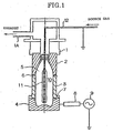
- Fig. 1 is a drawing showing one example of a manufacturing apparatus for manufacturing the plastic container for liquid medicines according to the present invention.
- Fig. 1 The applied symbols in Fig. 1 have the following meanings: 1 is a base, 1A is an exhaust outlet, 2 is a shoulder portion electrode, 3 is a body portion electrode, 4 is a bottom portion electrode, 5 is a plastic container, 6 is an insulator, 7 is an O-ring, 8 is an interface device, 9 is a high-frequency oscillator, 10 is a housing portion, 11 is an inner electrode, and 12 is a pipeline.
- Fig. 1 is a drawing showing the electrode structure and the like of the present apparatus.
- the present apparatus is equipped with a base 1, a shoulder portion electrode 2 and a body portion electrode 3 mounted to the base 1, and a bottom portion electrode 4 which can be connected to and disconnected from the body portion electrode 3.
- the shoulder portion electrode 2, the body portion electrode 3 and the bottom portion electrode 4 each have inner wall surfaces shaped like the outer shape of a plastic container 5, in which the shoulder portion electrode 2 is arranged along the shoulder portion of the plastic container 5, the body portion electrode 3 is arranged along the body portion of the plastic container 5, and the bottom portion electrode 4 is arranged along the bottom portion of the plastic container 5.
- the shoulder portion electrode 2, the body portion electrode 3 and the bottom portion electrode 4 form the outer electrodes of the present apparatus.
- the base 1, the shoulder portion electrode 2, the body portion electrode 3 and the bottom portion electrode 4 form a mutually airtight mounted state, and these function as a vacuum chamber equipped with a housing portion 10 for housing the plastic container 5.
- an insulator 6 is provided between the shoulder portion electrode 2 and the body portion electrode 3, and in this way the shoulder portion electrode 2 and the body portion electrode 3 are electrically insulated from each other. Further, an O-ring 7 is provided between the body portion electrode 3 and the bottom portion electrode 4, and when the bottom portion electrode 4 is mounted, a small gap is formed between the bottom portion electrode 4 and the body portion electrode 3. In this way, while ensuring airtightness between the bottom portion electrode 4 and the body portion electrode 3, electrical insulation is carried out between both electrodes.
- An inner electrode 11 is provided in the housing portion 10, and the inner electrode 11 is inserted into the inside of the plastic container 5 housed inside the housing portion 10.
- the inner electrode 11 is electrically connected to a ground potential.
- the inner electrode 11 is formed to have a hollow shape (tube shape), and one blowout hole (not shown in the drawing) which communicates the inside and the outside of the inner electrode 11 is formed in the lower end thereof. Further, instead of providing a blowout hole in the lower end, a plurality of blowout holes (not shown in the drawing) may be formed to pass through the inside and the outside of the inner electrode 11 in the radial direction.
- a pipeline 12 which communicates with the inside of the inner electrode 11 is connected to the inner electrode 11, and this structure makes it possible for a source gas fed into the inside of the inner electrode 11 via the pipeline 12 to be emitted into the inside of the plastic container 5 via the blowout hole.
- the pipeline 12 is made of metal and has electrical conductivity, and as shown in Fig. 1, the pipeline 12 is used to connect the inner electrode 11 to a ground potential. Further, the inner electrode 11 is supported by the pipeline 12.
- the output terminal of a high-frequency oscillator 9 is connected to the bottom portion electrode 4 via an interface device 8.
- the high-frequency oscillator 9 generates a high-frequency voltage between itself and the ground potential, and in this way a high-frequency voltage is applied between the inner electrode 11 and the bottom portion electrode 4.
- the plastic container 5 is set so that the bottom portion thereof makes contact with the inner surface of the bottom portion electrode 4, and by raising the bottom portion electrode 4, the plastic container 5 is housed in the housing portion 10. At this time, the inner electrode 11 provided in the housing portion 10 is inserted inside the plastic container 5 through the orifice (upper end opening) of the plastic container 5.
- a state is formed in which the outer periphery of the plastic container 5 makes contact with the inner surfaces of the shoulder portion electrode 2, the body portion electrode 3 and the bottom portion electrode 4.
- the air inside the housing portion 10 is exhausted through an exhaust outlet 1A of the base 1 by a vacuum device not shown in the drawing.
- a source gas e.g., carbon source gases such as aliphatic hydrocarbons, aromatic hydrocarbons and the like supplied via the pipeline 12 is introduced into the inside of the plastic container 5 from the blowout hole of the inner electrode 11.
- the high-frequency oscillator 9 (e.g., 13.56MHz) is activated to apply a high-frequency voltage between the inner electrode 11 and the outer electrodes, whereby a plasma is generated inside the plastic container 5. In this way, a DLC film is formed on the inner wall surfaces of the plastic container 5.
- the formation of a DLC film on the inner wall surfaces of the plastic container 5 is carried out by a plasma CVD method, wherein electrons accumulate on the inner wall surfaces of the outer electrodes insulated by the plasma generated between the outer electrodes and the inner electrode 11, and a prescribed fall in potential occurs.
- the carbon and the hydrogen of the hydrocarbon that forms the source gas present in the plasma are each ionized to positive.
- the ions will be attracted by and randomly collide with the inner wall surface of the plastic container 5 running along the inner wall surfaces of the outer electrodes, whereby an extremely dense hard carbon film made from DLC is formed on the inner wall surface of the plastic container 5 by the bonding between adjacent carbon atoms and the bonding between carbon atoms and hydrogen atoms, and by the breaking of bonds of hydrogen atoms that have bonded once (sputtering effect).
- the output terminal of the high-frequency oscillator 9 is connected to only the bottom portion electrode 4. Further, a gap is formed between the bottom portion electrode 4 and the body portion electrode 3, and the bottom portion electrode 4 and the body portion electrode 3 are electrically insulated from each other. Furthermore, the insulator 6 is provided between the body portion electrode 3 and the shoulder portion electrode 2, and the body portion electrode 3 and the shoulder portion electrode 2 are electrically insulated from each other. Accordingly, the high-frequency electric power applied to the body portion electrode 3 and the shoulder portion electrode 2 becomes smaller than the high-frequency electric power applied to the bottom portion electrode 4. However, because capacity coupling is carried out through the respective gaps between the bottom portion electrode 4 and the body portion electrode 3, and between the body portion electrode 3 and the shoulder portion electrode 2, a certain degree of high-frequency electric power is also applied to the body portion electrode 3 and the shoulder portion electrode 2.
- the bottom portion of plastic containers such as bottles and the like have complex shapes, and it is difficult to form a DLC film having a uniform film thickness, composition and density. For this reason, even after the DLC film is formed, the gas barrier properties of the bottom portion of the container are prone to lowering.
- the manufacturing apparatus of the embodiment described above because it is possible to apply high-frequency electric power larger than that for the body portion and shoulder portion to the bottom portion of the plastic container, it is possible to uniformly form a DLC film having a prescribed film thickness, composition and density on the entire bottle, and it is possible to effectively improve the gas barrier properties for the entire container.
- the applied electric power was 800 ⁇ 1400W.
- the shoulder portion electrode 2, the body portion electrode 3 and the bottom portion electrode 4 are constructed so as to be completely insulated against direct current, but it is also possible to connect each of the electrodes to each other by resistance or capacitive elements or the like.
- a plurality of high-frequency oscillators may be provided to apply high-frequency electric power separately to each of the electrodes of the shoulder portion electrode 2, the body portion electrode 3 and the bottom portion electrode 4, or the output of a single high-frequency oscillator may be connected to each of the electrodes via a plurality of interface devices.
- the outer electrodes are divided into three portions, but the outer electrodes may be divided into two portions, or the outer electrodes may be divided into four or more portions.
- a DLC film may be formed by a manufacturing apparatus based on a microwave plasma CVD method or the like.
- 500ml PET containers (weight 30g, thickness 0.3mm) were prepared in accordance with the principle of the present invention, and the inner surface area of these containers was 400cm 2 /container. Accordingly, the gas barrier properties are calculated per one container. In the case where these are converted per unit surface area (m 2 ), conversion may be carried out by considering the inner surface area of the container used for evaluation. Further, because there is almost no gas permeation from the cover, the surface area thereof does not enter into consideration.
- the present invention is not limited by the volume or shape of the containers of the example embodiments.
- the PET containers were formed using polyethylene terephthalate resin (Nihon Yunipet (Inc.) RT543 (Intrinsic Viscosity 0.77)).
- Table 1 shows the conditions for forming the DLC film in the present invention.
- Table 2 shows the various physical properties of the containers depending on the film thickness, density and composition (indicated by the hydrogen content) corresponding to the example embodiments of Table 1.
- the coating conditions were established as mentioned in Example Embodiment 1 of Table 1.
- the film thickness, density and composition of Example Embodiment 1 and the physical property values of the film thereof are shown in Table 2.
- DLC films were formed by shifting the conditions of the reference examples from the three conditions of film thickness, density and composition of the DLC films of the example embodiments.
- the coating conditions were established like the reference examples 1 ⁇ 13 of Table 1.
- the various physical properties of the containers at such time are shown in the same manner in Table 2.
- Example Embodiments Discharge Method High-Frequency Electric Power Film Forming Pressure Gas Flow Rate Thickness Density Hydrogen Atomic % w torr sccm ⁇ g/cm 3
- Example Embodiment 1 Bottom 800 0.05 31 180 1.6 40
- Example Embodiment 2 Bottom 800 0.05 31 350 1.6 40
- Example Embodiment 3 Bottom 1200 0.05 31 180 2.1 10
- Example Embodiment 5 Bottom 900 0.05 31 200 1.7 30
- Example Embodiment 6 Bottom 900 0.05 31 320 1.7 30
- Example Embodiment 7 Bottom 1200 0.05 31 200 2.0 15
- Example Embodiment 8 Bottom 1200 0.05 31 320 2.0 15
- Example Embodiment 9 Bottom 900 0.05 31 220 1.6 35
- Example Embodiment 10 Bottom 900 0.05 31 350 1.6 35
- Example Embodiment 11 Bottom 1200 0.03 31 220 2.1 10
- the three conditions of the DLC film are as follows. Namely, the composition condition is that the hydrogen atomic % is greater than or equal to 8 atomic % and less than 45 atomic %, and preferably 10 - 40 atomic %.
- the density condition is 1.3 ⁇ 2.2g/cm 3 , and preferably 1.4 ⁇ 2.0 g/cm 3 .
- the film thickness condition is 150 ⁇ 450 ⁇ , and preferably 180 ⁇ 420 ⁇ .
- the three conditions of the DLC film are as follows. Namely, the composition condition is that the hydrogen atomic % is greater than or equal to 10 atomic % and less than 40 atomic %, and preferably 15 ⁇ 35 atomic %.
- the density condition is greater than 1.6g/cm 3 and less than or equal to 2.1g/cm 3 , and preferably 1.7 ⁇ 2.0 g/cm 3 .
- the film thickness condition is 180 ⁇ 350 ⁇ , and preferably 200 ⁇ 320 ⁇ .
- the composition condition is that the hydrogen atomic % is greater than or equal to 10 atomic % and less than 40 atomic %, and preferably 15 ⁇ 35 atomic %.
- the density condition is 1.6g/cm 3 .
- the film thickness condition is 180 ⁇ 350 ⁇ , and preferably 200 ⁇ 320 ⁇ .
- the gas barrier properties of the carbon film coated containers of the present invention were such that the water vapor permeability was 0 ⁇ 0.006g/container/day, and the oxygen permeability was 0 ⁇ 0.011ml/container/day.
- a diamond state carbon film having a hydrogen concentration of 50 atomic % or less and an oxygen concentration of 2 ⁇ 20 atomic % is introduced.
- the oxygen permeability of 25 ⁇ m biaxial oriented polypropylene is 17.3 ml/m 2 /day, and the water vapor permeability is 4.5 g/m 2 /day which is an improvement of barrier properties by a factor of about 2 or 3 times.
- the inner surfaces of PET containers were covered by a 12 ⁇ m thick PET film, and the film obtained by forming a DLC film under the conditions of Example Embodiment 15 of Table 1 formed Example Embodiment 20, and the film obtained by forming a DLC film under the conditions of 17 of Table 1 formed Example Embodiment 21, and the various physical properties of these films are shown in Table 3.
- the 12 ⁇ m PET films of the present invention as shown in Example Embodiments 20, 21 of Table 3, in contrast with the films not formed with a DLC film, the oxygen gas barrier properties were about 100 times better, and the water vapor permeability was about 30 times better.
- Example Embodiment Film Thickness Density Composition Permeability Hydrogen Atom Content Oxygen Water ⁇ g/cm 3 Hydrogen Atomic % ml/m 2 / Day g/m 2 /Day Reference Example 14 (PET12 ⁇ m) 0 - - 85 45 Reference Example 15 (PET12 ⁇ m) 0 - - 100 50
- Example Embodiment 20 200 1.7 30 1.0 2.0
- Insulin mixed inside a transport liquid container is administered to diabetics during surgery or after surgery for the purpose of ketonic acidosis or blood sugar management or blood sugar value maintenance of a living person. In this case, adsorption on the plastic of the container has been pointed out.
- the DLC film coated PET container of the present invention was used to solve this problem.
- the insulin source liquid was adjusted as follows. Namely, cow insulin (25I.U./mg) manufactured by Shiguma Company was dissolved in a small amount of 0.1N hydrochloric acid solution, and distilled water was added for use as 40U/ml.
- Adjusted human globulin separated from human blood plasma components is used to treat infectious diseases and the like, but there arises a problem in the case of an injection liquid because of adsorption on the plastic container due to hydrophobic properties.
- the DLC film coated PET container of the present invention was used to solve this problem.
- ⁇ -globulin a Fraction II manufactured by Seikagaku Corporation was used. The analysis of ⁇ -globulin was based on a colorimetric method according to the Lowry method.
- the recovery percentage was calculated in the same manner as the example embodiments (adsorption of insulin). In each test section, the results carried out for 5 rows formed the average of the 5 rows. Measurements were carried out for DLC film coated containers manufactured under the conditions of Table 4. The recovery percentage of ⁇ -globulin for the plastic containers for liquid medicine according to the present invention are shown in Table 6. In the example embodiments 22 - 27 of Table 6, ⁇ -globulin recovery percentages greater than 97% were obtained, and these results were understood to mean that the containers have low adsorptivity of effective components of medicine.
- Reference Example 16 95.0 Reference Example 17 95.3 Reference Example 18 (Only PET) 94.6
- a 0.9% sodium chloride solution was placed in each 500ml volume plastic container, and then the medicines described above were added to form the concentrations shown in Table 7, whereafter such containers were left alone in a dark place at room temperature for one week. Then, the concentration of each medicine was measured, and the proportion of recovered medicine which was not adsorbed from the solution was calculated.
- the measurement of the concentration of each medicine was calculated by the light absorbance due to ultraviolet absorption. The measured wavelengths are shown in Table 7. Further, at the time of measurements, the Diazepam was diluted by 0.1N sulfuric acid, and the others were diluted by water to form concentrations which were easy to measure. In each test section, the results carried out for 5 rows formed the average of the 5 rows. Measurements were carried out for DLC film coated containers manufactured under the conditions of Table 4. The recovery percentage of synthetic medicines after container storage for the plastic containers for liquid medicine according to the present invention are shown in Table 7.
- the present invention improves the recovery percentage of medicines, and this proves that the present invention is useful.
- the recovery percentages were greater than 98%.
- the three conditions of the DLC film are as follows from the viewpoint of the low adsorptivity of effective components of medicine.
- the composition condition is that the hydrogen atomic % is greater than or equal to 8 atomic % and less than 35 atomic %, and preferably 8 ⁇ 26 atomic %.
- the density condition is greater than 1.6g/cm 3 and less than or equal to 2.2g/cm 3 , and preferably 1.8 ⁇ 2.2g/cm 3 .
- the film thickness condition is 100 ⁇ 450 ⁇ , and preferably 100 ⁇ 40 0 ⁇ .
- the three conditions of the DLC film are as follows. Namely, the composition condition is that the hydrogen atomic % is greater than or equal to 10 atomic % and less than 40 atomic %, and preferably 15 ⁇ 26 atomic %.
- the density condition is 1.6g/cm 3 .
- the film thickness condition is 180 ⁇ 350 ⁇ , and preferably 200 ⁇ 320 ⁇ .
- Syringes capable of holding 50ml of solution were made from each plastic, and inside these a heparin source liquid was added to 50ml of a 0.9% sodium chloride solution to form a solution having 500units/ml, and then the syringes were plugged and left alone at room temperature for two weeks. After two weeks, the heparin activity inside the solution was measured, and the effect on heparin activity of each container was examined.
- the measurement of heparin activity was carried out by the method of Babson et al. (Am. J Clin Pathol. 62, 856(1974)). In each test section, the results carried out for 5 rows formed the average of the 5 rows.
- example embodiments 28 ⁇ 33 compared with the reference examples, it is clear that the present invention preserves the maintenance of the activity of the heparin solution.
- the activity maintenance percentage was greater than 94%. Accordingly, in the example embodiments there was considered to be almost no (1) adsorption onto the container inner wall surfaces and no (2) bonding with eluted material from inside the resin which lower the activity of heparin.
Landscapes
- Chemical & Material Sciences (AREA)
- Engineering & Computer Science (AREA)
- Mechanical Engineering (AREA)
- Organic Chemistry (AREA)
- General Chemical & Material Sciences (AREA)
- Health & Medical Sciences (AREA)
- Metallurgy (AREA)
- Materials Engineering (AREA)
- Chemical Kinetics & Catalysis (AREA)
- Ceramic Engineering (AREA)
- Pharmacology & Pharmacy (AREA)
- Life Sciences & Earth Sciences (AREA)
- General Health & Medical Sciences (AREA)
- Animal Behavior & Ethology (AREA)
- Veterinary Medicine (AREA)
- Public Health (AREA)
- Inorganic Chemistry (AREA)
- Medical Preparation Storing Or Oral Administration Devices (AREA)
- Details Of Rigid Or Semi-Rigid Containers (AREA)
- Packages (AREA)
Applications Claiming Priority (3)
| Application Number | Priority Date | Filing Date | Title |
|---|---|---|---|
| JP2000048388 | 2000-02-24 | ||
| JP2000048388A JP4492985B2 (ja) | 2000-02-24 | 2000-02-24 | 液体医薬品用プラスチック容器及び液体医薬品の保存回収方法 |
| PCT/JP2001/001296 WO2001062202A1 (en) | 2000-02-24 | 2001-02-22 | Plastic container for liquid medicine |
Publications (3)
| Publication Number | Publication Date |
|---|---|
| EP1258234A1 EP1258234A1 (en) | 2002-11-20 |
| EP1258234A4 EP1258234A4 (en) | 2005-01-05 |
| EP1258234B1 true EP1258234B1 (en) | 2006-06-14 |
Family
ID=18570477
Family Applications (1)
| Application Number | Title | Priority Date | Filing Date |
|---|---|---|---|
| EP01906205A Revoked EP1258234B1 (en) | 2000-02-24 | 2001-02-22 | Plastic container for liquid medicine |
Country Status (9)
| Country | Link |
|---|---|
| US (1) | US7029752B2 (enExample) |
| EP (1) | EP1258234B1 (enExample) |
| JP (1) | JP4492985B2 (enExample) |
| CN (1) | CN1404381A (enExample) |
| AT (1) | ATE329563T1 (enExample) |
| AU (2) | AU2001234123B2 (enExample) |
| DE (1) | DE60120645D1 (enExample) |
| HK (1) | HK1052455A1 (enExample) |
| WO (1) | WO2001062202A1 (enExample) |
Cited By (1)
| Publication number | Priority date | Publication date | Assignee | Title |
|---|---|---|---|---|
| WO2010095011A1 (en) | 2009-02-18 | 2010-08-26 | Council Of Scientific & Industrial Research | Process to deposit diamond like carbon as protective coating on inner surface of a shaped object. |
Families Citing this family (49)
| Publication number | Priority date | Publication date | Assignee | Title |
|---|---|---|---|---|
| DE60031544T2 (de) * | 1999-05-19 | 2007-08-02 | Mitsubishi Shoji Plastics Corp. | Dlc-film, dlc-beschichteter plastikbehälter und verfahren und vorrichtung zur herstellung solcher behälter |
| JP2001240115A (ja) * | 2000-02-24 | 2001-09-04 | Mitsubishi Shoji Plast Kk | 乾燥固体食品用プラスチック容器 |
| EP1245217B1 (en) * | 2001-03-27 | 2009-10-28 | Nipro Corporation | Plastic container containing albumin solution |
| KR20050007341A (ko) * | 2002-04-26 | 2005-01-17 | 호카이세이칸가부시끼가이샤 | 내면 피복 플라스틱 용기 및 그 제조 방법 |
| JP4132982B2 (ja) * | 2002-05-28 | 2008-08-13 | 麒麟麦酒株式会社 | Dlc膜コーティングプラスチック容器の製造装置 |
| KR100961419B1 (ko) * | 2002-05-28 | 2010-06-09 | 기린비루 가부시키가이샤 | Dlc막 코팅 플라스틱 용기, 그 제조장치 및 제조방법 |
| AU2004251810B2 (en) | 2003-06-27 | 2010-03-04 | Novo Nordisk A/S | High moisture barrier container for medical liquid compositions |
| EP1699629B1 (en) * | 2003-12-22 | 2010-10-06 | Novo Nordisk A/S | Transparent, flexible , impermeable plastic container for storage of pharmaceutical liquids |
| CN101102739B (zh) | 2005-01-12 | 2017-02-08 | 比奥根Ma公司 | 运输干扰素‑β的方法 |
| DK1875889T3 (en) * | 2005-04-28 | 2014-12-08 | Otsuka Pharma Co Ltd | Medical liquid container storage body and method of manufacture thereof |
| AU2006250336B2 (en) * | 2005-05-27 | 2011-07-21 | Kirin Beer Kabushiki Kaisha | Apparatus for manufacturing gas barrier plastic container, method for manufacturing the container, and the container |
| DE102005040266A1 (de) * | 2005-08-24 | 2007-03-01 | Schott Ag | Verfahren und Vorrichtung zur innenseitigen Plasmabehandlung von Hohlkörpern |
| US20090142525A1 (en) * | 2005-09-09 | 2009-06-04 | Sidel Participations | Barrier layer |
| US8025915B2 (en) * | 2006-01-11 | 2011-09-27 | Schott Ag | Method of preparing a macromolecule deterrent surface on a pharmaceutical package |
| HUE027439T2 (hu) * | 2006-10-27 | 2016-10-28 | Otsuka Pharma Factory Inc | Hatóanyag-oldatot tartalmazó csomagolás csökkentett oldottoxigén-tartalommal |
| EP3536363A1 (en) * | 2008-09-22 | 2019-09-11 | Becton, Dickinson and Company | Systems for coating the interior of a container |
| US7993609B2 (en) * | 2008-12-30 | 2011-08-09 | Sterilucent, Inc. | Package for chemicals |
| EP2251452B1 (en) | 2009-05-13 | 2018-07-18 | SiO2 Medical Products, Inc. | Pecvd apparatus for vessel coating |
| JP5710600B2 (ja) * | 2009-05-13 | 2015-04-30 | エスアイオーツー・メディカル・プロダクツ・インコーポレイテッド | 被覆表面検査のためのガス放出方法 |
| US20110001103A1 (en) * | 2009-07-01 | 2011-01-06 | Chi-Kuang Chen | Elevating mechanism for measuring concentrations of medicines |
| US9458536B2 (en) | 2009-07-02 | 2016-10-04 | Sio2 Medical Products, Inc. | PECVD coating methods for capped syringes, cartridges and other articles |
| US9522773B2 (en) | 2009-07-09 | 2016-12-20 | Entegris, Inc. | Substantially rigid collapsible liner and flexible gusseted or non-gusseted liners and methods of manufacturing the same and methods for limiting choke-off in liners |
| US20110152820A1 (en) * | 2009-12-22 | 2011-06-23 | Medtronic Minimed, Inc. | Barrier coatings for fluids contacting medical devices |
| US11624115B2 (en) | 2010-05-12 | 2023-04-11 | Sio2 Medical Products, Inc. | Syringe with PECVD lubrication |
| US9878101B2 (en) | 2010-11-12 | 2018-01-30 | Sio2 Medical Products, Inc. | Cyclic olefin polymer vessels and vessel coating methods |
| TW201242670A (en) | 2010-11-23 | 2012-11-01 | Advanced Tech Materials | Liner-based dispenser |
| DE102011009056B4 (de) * | 2011-01-20 | 2016-04-07 | Schott Ag | Vorrichtung zur Plasmabehandlung von Hohlkörpern |
| BR112013022316A2 (pt) | 2011-03-01 | 2017-05-30 | Advanced Tech Materials | sistema baseado em revestimento interno, e, método para prover um sistema baseado em revestimento interno |
| US9272095B2 (en) | 2011-04-01 | 2016-03-01 | Sio2 Medical Products, Inc. | Vessels, contact surfaces, and coating and inspection apparatus and methods |
| EP2737890B1 (en) * | 2011-07-28 | 2018-08-22 | Terumo Kabushiki Kaisha | Red-blood-cell storage container |
| US11116695B2 (en) | 2011-11-11 | 2021-09-14 | Sio2 Medical Products, Inc. | Blood sample collection tube |
| CN103930595A (zh) | 2011-11-11 | 2014-07-16 | Sio2医药产品公司 | 用于药物包装的钝化、pH保护性或润滑性涂层、涂布方法以及设备 |
| US9068565B2 (en) | 2012-05-03 | 2015-06-30 | Becton, Dickinson And Company | Container and method for storing a pharmaceutical agent |
| EP2846755A1 (en) | 2012-05-09 | 2015-03-18 | SiO2 Medical Products, Inc. | Saccharide protective coating for pharmaceutical package |
| US20150297800A1 (en) | 2012-07-03 | 2015-10-22 | Sio2 Medical Products, Inc. | SiOx BARRIER FOR PHARMACEUTICAL PACKAGE AND COATING PROCESS |
| US9404334B2 (en) | 2012-08-31 | 2016-08-02 | Baker Hughes Incorporated | Downhole elastomeric components including barrier coatings |
| US9664626B2 (en) | 2012-11-01 | 2017-05-30 | Sio2 Medical Products, Inc. | Coating inspection method |
| WO2014078666A1 (en) | 2012-11-16 | 2014-05-22 | Sio2 Medical Products, Inc. | Method and apparatus for detecting rapid barrier coating integrity characteristics |
| EP2925903B1 (en) | 2012-11-30 | 2022-04-13 | Si02 Medical Products, Inc. | Controlling the uniformity of pecvd deposition on medical syringes, cartridges, and the like |
| US9764093B2 (en) | 2012-11-30 | 2017-09-19 | Sio2 Medical Products, Inc. | Controlling the uniformity of PECVD deposition |
| US9662450B2 (en) | 2013-03-01 | 2017-05-30 | Sio2 Medical Products, Inc. | Plasma or CVD pre-treatment for lubricated pharmaceutical package, coating process and apparatus |
| WO2014164928A1 (en) | 2013-03-11 | 2014-10-09 | Sio2 Medical Products, Inc. | Coated packaging |
| US9937099B2 (en) | 2013-03-11 | 2018-04-10 | Sio2 Medical Products, Inc. | Trilayer coated pharmaceutical packaging with low oxygen transmission rate |
| WO2014144926A1 (en) | 2013-03-15 | 2014-09-18 | Sio2 Medical Products, Inc. | Coating method |
| EP3122917B1 (en) | 2014-03-28 | 2020-05-06 | SiO2 Medical Products, Inc. | Antistatic coatings for plastic vessels |
| EP3059330A1 (en) * | 2015-02-23 | 2016-08-24 | Toto Ltd. | Wet area member |
| JP6563730B2 (ja) * | 2015-07-31 | 2019-08-21 | 神港精機株式会社 | ダイヤモンドライクカーボン粉末およびその作製方法 |
| EP4001456A1 (en) | 2015-08-18 | 2022-05-25 | SiO2 Medical Products, Inc. | Pharmaceutical and other packaging with low oxygen transmission rate |
| CN115613004A (zh) * | 2021-07-12 | 2023-01-17 | 北京印刷学院 | 内壁镀膜的塑料管及制备方法 |
Family Cites Families (7)
| Publication number | Priority date | Publication date | Assignee | Title |
|---|---|---|---|---|
| US4809876A (en) * | 1987-08-27 | 1989-03-07 | Aluminum Company Of America | Container body having improved gas barrier properties |
| JP2788412B2 (ja) | 1994-08-11 | 1998-08-20 | 麒麟麦酒株式会社 | 炭素膜コーティングプラスチック容器の製造装置および製造方法 |
| JPH0853116A (ja) * | 1994-08-11 | 1996-02-27 | Kirin Brewery Co Ltd | 炭素膜コーティングプラスチック容器 |
| JP3072269B2 (ja) * | 1997-02-19 | 2000-07-31 | 麒麟麦酒株式会社 | 炭素膜コーティングプラスチック容器の製造装置および製造方法 |
| JPH1170152A (ja) | 1997-06-16 | 1999-03-16 | Mitsui Chem Inc | 薬品容器用フィルム |
| JP2000185997A (ja) * | 1998-12-24 | 2000-07-04 | Daiei Seiko Kk | ダイヤモンドライクカーボン膜形成装置およびダイヤモンドライクカーボン膜形成方法 |
| JP3901888B2 (ja) * | 1999-05-19 | 2007-04-04 | 北海製罐株式会社 | ダイヤモンドライクカーボン膜コーティングプラスチック容器の製造装置及びその製造方法 |
-
2000
- 2000-02-24 JP JP2000048388A patent/JP4492985B2/ja not_active Expired - Lifetime
-
2001
- 2001-02-22 AU AU2001234123A patent/AU2001234123B2/en not_active Ceased
- 2001-02-22 AU AU3412301A patent/AU3412301A/xx active Pending
- 2001-02-22 CN CN01805338A patent/CN1404381A/zh active Pending
- 2001-02-22 US US10/182,812 patent/US7029752B2/en not_active Expired - Lifetime
- 2001-02-22 EP EP01906205A patent/EP1258234B1/en not_active Revoked
- 2001-02-22 DE DE60120645T patent/DE60120645D1/de not_active Expired - Lifetime
- 2001-02-22 AT AT01906205T patent/ATE329563T1/de not_active IP Right Cessation
- 2001-02-22 WO PCT/JP2001/001296 patent/WO2001062202A1/ja not_active Ceased
- 2001-02-22 HK HK03104919.7A patent/HK1052455A1/zh unknown
Cited By (2)
| Publication number | Priority date | Publication date | Assignee | Title |
|---|---|---|---|---|
| WO2010095011A1 (en) | 2009-02-18 | 2010-08-26 | Council Of Scientific & Industrial Research | Process to deposit diamond like carbon as protective coating on inner surface of a shaped object. |
| EP2589680A1 (en) | 2009-02-18 | 2013-05-08 | Council of Scientific & Industrial Research | Apparatus for the deposition of diamondlike carbon as protective coating on an inner surface of a shaped object |
Also Published As
| Publication number | Publication date |
|---|---|
| AU3412301A (en) | 2001-09-03 |
| CN1404381A (zh) | 2003-03-19 |
| EP1258234A4 (en) | 2005-01-05 |
| US7029752B2 (en) | 2006-04-18 |
| HK1052455A1 (zh) | 2003-09-19 |
| WO2001062202A1 (en) | 2001-08-30 |
| DE60120645D1 (de) | 2006-07-27 |
| JP2001231841A (ja) | 2001-08-28 |
| JP4492985B2 (ja) | 2010-06-30 |
| EP1258234A1 (en) | 2002-11-20 |
| US20040050744A1 (en) | 2004-03-18 |
| ATE329563T1 (de) | 2006-07-15 |
| AU2001234123B2 (en) | 2004-06-03 |
Similar Documents
| Publication | Publication Date | Title |
|---|---|---|
| EP1258234B1 (en) | Plastic container for liquid medicine | |
| KR100540401B1 (ko) | 의약용액의저장및혼합을위한용기및그방법 | |
| US7807242B2 (en) | Transparent, flexible, impermeable plastic container for storage of pharmaceutical liquids | |
| KR100351555B1 (ko) | 비경구유체용용기 | |
| EP2925903B1 (en) | Controlling the uniformity of pecvd deposition on medical syringes, cartridges, and the like | |
| EP1154902B1 (en) | New use | |
| EP3171868B1 (en) | Packaged acetaminophen injection solution preparation | |
| EP1245217B1 (en) | Plastic container containing albumin solution | |
| RU2381103C2 (ru) | Контейнер для жидких фармацевтических композиций с высокими влагозащитными свойствами | |
| EP1860436B1 (en) | Blood coagulation accelerator and vessel for blood test | |
| CN113825483A (zh) | 聚合物处理袋及其制造方法 | |
| EP3991711A1 (en) | Pharmaceutical packages comprising polypropylene containers and ngf aqueous formulations packaged therein | |
| EP3290025A1 (en) | Stable infusion dosage form of morphine | |
| US20080311321A1 (en) | Multilayer Film With Septum Layer | |
| EP4023202A1 (en) | Medicinal product comprising a flexible plastic bag and an aqueous, ready-to-use solution of midazolam | |
| JPWO2005004902A1 (ja) | プラスチック容器入り組換えヒト血清アルブミン製剤 | |
| RU2841328C1 (ru) | Фармацевтические упаковки, содержащие полипропиленовые контейнеры и упакованные в них водные препараты ngf | |
| JP2000510419A (ja) | バリアー性被覆を有する可撓性の容器又は瓶型容器 | |
| EP1169074B1 (en) | Process for determining the suitability of a sealing member for a storage container for weakly acidic solution formulations containing human growth hormone | |
| CN118557707A (zh) | 德谷胰岛素注射液的制备方法 |
Legal Events
| Date | Code | Title | Description |
|---|---|---|---|
| PUAI | Public reference made under article 153(3) epc to a published international application that has entered the european phase |
Free format text: ORIGINAL CODE: 0009012 |
|
| 17P | Request for examination filed |
Effective date: 20020814 |
|
| AK | Designated contracting states |
Kind code of ref document: A1 Designated state(s): AT BE CH CY DE DK ES FI FR GB GR IE IT LI LU MC NL PT SE TR |
|
| AX | Request for extension of the european patent |
Free format text: AL;LT;LV;MK;RO;SI |
|
| A4 | Supplementary search report drawn up and despatched |
Effective date: 20041118 |
|
| RIC1 | Information provided on ipc code assigned before grant |
Ipc: 7B 65D 1/02 B Ipc: 7C 23C 16/26 B Ipc: 7B 65D 23/02 B Ipc: 7A 61J 1/00 A |
|
| 17Q | First examination report despatched |
Effective date: 20050304 |
|
| GRAP | Despatch of communication of intention to grant a patent |
Free format text: ORIGINAL CODE: EPIDOSNIGR1 |
|
| GRAS | Grant fee paid |
Free format text: ORIGINAL CODE: EPIDOSNIGR3 |
|
| GRAA | (expected) grant |
Free format text: ORIGINAL CODE: 0009210 |
|
| AK | Designated contracting states |
Kind code of ref document: B1 Designated state(s): AT BE CH CY DE DK ES FI FR GB GR IE IT LI LU MC NL PT SE TR |
|
| PG25 | Lapsed in a contracting state [announced via postgrant information from national office to epo] |
Ref country code: IT Free format text: LAPSE BECAUSE OF FAILURE TO SUBMIT A TRANSLATION OF THE DESCRIPTION OR TO PAY THE FEE WITHIN THE PRESCRIBED TIME-LIMIT;WARNING: LAPSES OF ITALIAN PATENTS WITH EFFECTIVE DATE BEFORE 2007 MAY HAVE OCCURRED AT ANY TIME BEFORE 2007. THE CORRECT EFFECTIVE DATE MAY BE DIFFERENT FROM THE ONE RECORDED. Effective date: 20060614 Ref country code: AT Free format text: LAPSE BECAUSE OF FAILURE TO SUBMIT A TRANSLATION OF THE DESCRIPTION OR TO PAY THE FEE WITHIN THE PRESCRIBED TIME-LIMIT Effective date: 20060614 Ref country code: LI Free format text: LAPSE BECAUSE OF FAILURE TO SUBMIT A TRANSLATION OF THE DESCRIPTION OR TO PAY THE FEE WITHIN THE PRESCRIBED TIME-LIMIT Effective date: 20060614 Ref country code: FI Free format text: LAPSE BECAUSE OF FAILURE TO SUBMIT A TRANSLATION OF THE DESCRIPTION OR TO PAY THE FEE WITHIN THE PRESCRIBED TIME-LIMIT Effective date: 20060614 Ref country code: BE Free format text: LAPSE BECAUSE OF FAILURE TO SUBMIT A TRANSLATION OF THE DESCRIPTION OR TO PAY THE FEE WITHIN THE PRESCRIBED TIME-LIMIT Effective date: 20060614 Ref country code: CH Free format text: LAPSE BECAUSE OF FAILURE TO SUBMIT A TRANSLATION OF THE DESCRIPTION OR TO PAY THE FEE WITHIN THE PRESCRIBED TIME-LIMIT Effective date: 20060614 Ref country code: NL Free format text: LAPSE BECAUSE OF FAILURE TO SUBMIT A TRANSLATION OF THE DESCRIPTION OR TO PAY THE FEE WITHIN THE PRESCRIBED TIME-LIMIT Effective date: 20060614 |
|
| REG | Reference to a national code |
Ref country code: GB Ref legal event code: FG4D |
|
| REG | Reference to a national code |
Ref country code: CH Ref legal event code: EP |
|
| REG | Reference to a national code |
Ref country code: IE Ref legal event code: FG4D |
|
| REF | Corresponds to: |
Ref document number: 60120645 Country of ref document: DE Date of ref document: 20060727 Kind code of ref document: P |
|
| PG25 | Lapsed in a contracting state [announced via postgrant information from national office to epo] |
Ref country code: DK Free format text: LAPSE BECAUSE OF FAILURE TO SUBMIT A TRANSLATION OF THE DESCRIPTION OR TO PAY THE FEE WITHIN THE PRESCRIBED TIME-LIMIT Effective date: 20060914 Ref country code: SE Free format text: LAPSE BECAUSE OF FAILURE TO SUBMIT A TRANSLATION OF THE DESCRIPTION OR TO PAY THE FEE WITHIN THE PRESCRIBED TIME-LIMIT Effective date: 20060914 |
|
| PG25 | Lapsed in a contracting state [announced via postgrant information from national office to epo] |
Ref country code: DE Free format text: LAPSE BECAUSE OF FAILURE TO SUBMIT A TRANSLATION OF THE DESCRIPTION OR TO PAY THE FEE WITHIN THE PRESCRIBED TIME-LIMIT Effective date: 20060915 |
|
| PG25 | Lapsed in a contracting state [announced via postgrant information from national office to epo] |
Ref country code: ES Free format text: LAPSE BECAUSE OF FAILURE TO SUBMIT A TRANSLATION OF THE DESCRIPTION OR TO PAY THE FEE WITHIN THE PRESCRIBED TIME-LIMIT Effective date: 20060925 |
|
| PG25 | Lapsed in a contracting state [announced via postgrant information from national office to epo] |
Ref country code: PT Free format text: LAPSE BECAUSE OF FAILURE TO SUBMIT A TRANSLATION OF THE DESCRIPTION OR TO PAY THE FEE WITHIN THE PRESCRIBED TIME-LIMIT Effective date: 20061114 |
|
| NLV1 | Nl: lapsed or annulled due to failure to fulfill the requirements of art. 29p and 29m of the patents act | ||
| REG | Reference to a national code |
Ref country code: CH Ref legal event code: PL |
|
| PG25 | Lapsed in a contracting state [announced via postgrant information from national office to epo] |
Ref country code: MC Free format text: LAPSE BECAUSE OF NON-PAYMENT OF DUE FEES Effective date: 20070228 |
|
| PLBI | Opposition filed |
Free format text: ORIGINAL CODE: 0009260 |
|
| PLAX | Notice of opposition and request to file observation + time limit sent |
Free format text: ORIGINAL CODE: EPIDOSNOBS2 |
|
| 26 | Opposition filed |
Opponent name: SIDEL PARTICIPATIONS S.A.S. Effective date: 20070314 |
|
| EN | Fr: translation not filed | ||
| PLBB | Reply of patent proprietor to notice(s) of opposition received |
Free format text: ORIGINAL CODE: EPIDOSNOBS3 |
|
| RDAF | Communication despatched that patent is revoked |
Free format text: ORIGINAL CODE: EPIDOSNREV1 |
|
| RDAG | Patent revoked |
Free format text: ORIGINAL CODE: 0009271 |
|
| STAA | Information on the status of an ep patent application or granted ep patent |
Free format text: STATUS: PATENT REVOKED |
|
| 27W | Patent revoked |
Effective date: 20070616 |
|
| GBPR | Gb: patent revoked under art. 102 of the ep convention designating the uk as contracting state |
Free format text: 20070616 |
|
| PG25 | Lapsed in a contracting state [announced via postgrant information from national office to epo] |
Ref country code: GR Free format text: LAPSE BECAUSE OF FAILURE TO SUBMIT A TRANSLATION OF THE DESCRIPTION OR TO PAY THE FEE WITHIN THE PRESCRIBED TIME-LIMIT Effective date: 20060915 Ref country code: FR Free format text: LAPSE BECAUSE OF FAILURE TO SUBMIT A TRANSLATION OF THE DESCRIPTION OR TO PAY THE FEE WITHIN THE PRESCRIBED TIME-LIMIT Effective date: 20070309 |
|
| PG25 | Lapsed in a contracting state [announced via postgrant information from national office to epo] |
Ref country code: FR Free format text: LAPSE BECAUSE OF FAILURE TO SUBMIT A TRANSLATION OF THE DESCRIPTION OR TO PAY THE FEE WITHIN THE PRESCRIBED TIME-LIMIT Effective date: 20060614 |