EP1256313A2 - Am Handgelenk zu tragende Manschette eines Blutdruckmessgeräts - Google Patents
Am Handgelenk zu tragende Manschette eines Blutdruckmessgeräts Download PDFInfo
- Publication number
- EP1256313A2 EP1256313A2 EP02009705A EP02009705A EP1256313A2 EP 1256313 A2 EP1256313 A2 EP 1256313A2 EP 02009705 A EP02009705 A EP 02009705A EP 02009705 A EP02009705 A EP 02009705A EP 1256313 A2 EP1256313 A2 EP 1256313A2
- Authority
- EP
- European Patent Office
- Prior art keywords
- wrist
- blood pressure
- air bag
- cuff
- inflatable portion
- Prior art date
- Legal status (The legal status is an assumption and is not a legal conclusion. Google has not performed a legal analysis and makes no representation as to the accuracy of the status listed.)
- Granted
Links
Images


Classifications
-
- A—HUMAN NECESSITIES
- A61—MEDICAL OR VETERINARY SCIENCE; HYGIENE
- A61B—DIAGNOSIS; SURGERY; IDENTIFICATION
- A61B5/00—Measuring for diagnostic purposes; Identification of persons
- A61B5/68—Arrangements of detecting, measuring or recording means, e.g. sensors, in relation to patient
- A61B5/6801—Arrangements of detecting, measuring or recording means, e.g. sensors, in relation to patient specially adapted to be attached to or worn on the body surface
- A61B5/6802—Sensor mounted on worn items
- A61B5/681—Wristwatch-type devices
-
- A—HUMAN NECESSITIES
- A61—MEDICAL OR VETERINARY SCIENCE; HYGIENE
- A61B—DIAGNOSIS; SURGERY; IDENTIFICATION
- A61B5/00—Measuring for diagnostic purposes; Identification of persons
- A61B5/02—Detecting, measuring or recording for evaluating the cardiovascular system, e.g. pulse, heart rate, blood pressure or blood flow
- A61B5/021—Measuring pressure in heart or blood vessels
- A61B5/02141—Details of apparatus construction, e.g. pump units or housings therefor, cuff pressurising systems, arrangements of fluid conduits or circuits
-
- A—HUMAN NECESSITIES
- A61—MEDICAL OR VETERINARY SCIENCE; HYGIENE
- A61B—DIAGNOSIS; SURGERY; IDENTIFICATION
- A61B5/00—Measuring for diagnostic purposes; Identification of persons
- A61B5/02—Detecting, measuring or recording for evaluating the cardiovascular system, e.g. pulse, heart rate, blood pressure or blood flow
- A61B5/021—Measuring pressure in heart or blood vessels
- A61B5/022—Measuring pressure in heart or blood vessels by applying pressure to close blood vessels, e.g. against the skin; Ophthalmodynamometers
- A61B5/02233—Occluders specially adapted therefor
Definitions
- the present invention relates to a cuff of a blood pressure monitor for measuring the blood pressure as being mounted on the body of a subject, and more particularly relates to a structure of the cuff of a wrist-mount blood pressure monitor used in a wrist-mount blood pressure monitor for measuring the blood pressure on the wrist.
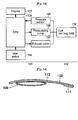
- Fig. 12 is a general perspective view showing the appearance of the wrist-mount blood pressure monitor 100
- Fig. 13 is a block diagram showing an internal structure of the wrist-mount blood pressure monitor 100.
- the wrist-mount blood pressure monitor 100 comprises a main body 101 incorporating a control device for measuring the blood pressure, and a cuff 102 of a wrist-mount blood pressure monitor to which the main body 101 is attached.
- a display 103 and a start switch 104 are provided on the outer surface of the main body 101, and a pressure sensor 105, a pressurizing pump 106, an exhaust valve 107, and a CPU 108 for controlling these devices are provided in its inside.
- the cuff 102 of wrist-mount blood pressure monitor comprises an air bag 109 for collecting the air sent out from the pressurizing pump 106 and oppressing an artery of the wrist, a band 110 having the air bag 109 disposed at its inner side for mounting on the wrist, and a fastener 111 for winding and fixing the band 110 on the wrist.
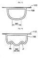
- Fig. 14 is a schematic sectional view of the cuff 102 of the wrist-mount blood pressure monitor along the longitudinal direction before mounting on the wrist, and air is not supplied into the air bag 109 yet.
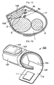
- Fig. 15 is a sectional diagram showing a deflated state of the cuff 102 of the wrist-mount blood pressure monitor mounted on the wrist 1.
- Fig. 16 is a sectional view showing an inflated state of the cuff 102 of the wrist-mount blood pressure monitor mounted on the wrist 1.
- the cuff 102 of the wrist-mount blood pressure monitor shown in Fig. 14 is fixed by using the band 110 so that the air bag 109 comes to a position confronting the radial artery 5 and ulnar artery 7 of the wrist 1.
- the principal constituents of the wrist 1 include, as shown in Fig. 15, the radius 2 positioned at the thumb side, the ulna 3 positioned as the little finger side, the deep flexor digital tendon 4a and palmar long flexor tendon 4b positioned near the radius 2, the radial artery 5, the superficial flexor digital tendon 6a and ulnar carpal tendon 6b positioned near the ulna 3, and the ulnar artery 7.
- the wrist-mount blood pressure monitor is said to be inferior in precision to the brachial type blood pressure monitor.
- One of the causes is lack of oppression force on the artery of the wrist.
- Lack of oppression force on the artery means that the pressure of the vascular inner wall to be measure (hereinafter called vascular inner wall pressure) is smaller as compared with the air bag inner pressure.
- oppression force when the oppression force is insufficient, the air bag inner pressure becomes higher than the vascular inner wall pressure, and the air bag inner pressure is directly measured as the blood pressure, so that a higher blood pressure than the actual pressure is measured.
- oppression width hereinafter cuff width
- the guideline of cuff width of brachial type blood pressure monitor is specified by AHA (American Heart Association), but there is no guideline for the cuff width of wrist-mount blood pressure monitor. Accordingly, the definition of cuff width of the brachial type blood pressure monitor (width of specific multiple of diameter of applicable brachial girth) is directly applied to the wrist. At the present, the cuff width of wrist-mount blood pressure monitor is set at about 50 to 60 mm. If the cuff width of the wrist-mount blood pressure monitor is determined according to this definition, lack of oppression force occurs. One of the causes is that the wrist contains many muscles and tendons not existing in the brachium, and the bones are present relatively near the cuticle, and the oppression of artery by the air bag is impeded.
- a sufficient air is supplied in the air bag 109, and the air bag 109 is inflated toward the wrist 1 side.
- the inflation of the air bag 109 is impeded, and the radial artery 5 is not oppressed sufficiently, and also the inflation of the air bag 109 is impeded by the presence of the superficial flexor digital tendon 6a and ulnar carpal tendon 6b, and the ulnar artery 7 is not sufficiently oppressed.
- a specified cuff width W1 can be obtained by sufficiently inflating the air bag 109, but in the presence of the radius 2, palmar long flexor tendon 4b, and others, as schematically shown in Fig. 18, inflation of the air bag 109 is impeded by the presence of the radius 2, palmar long flexor tendon 4b, and others, and hence the cuff width W2 is insufficient.
- the cuff of a wrist-mount blood pressure monitor comprises an inflatable bag receiving a predetermined amount of a fluid for pressurizing an artery of the wrist, and mounting means for mounting the inflatable bag on the wrist, in which the inflatable bag includes a first inflatable portion, and a second inflatable portion disposed between the first inflatable portion and the wrist, being made of a material having a higher stretchability than the material of the first inflatable portion.
- both the first inflatable portion and second inflatable portion are inflated by the supply of the fluid. Since the second inflatable portion is made of a material having a higher stretchability than the material of the first inflatable portion, a specified pressure to the wrist side is assured by inflation of the first inflatable portion. Moreover, the second inflatable portion is inflated in a state of tight contact with the wrist, the second inflatable portion flexibly intrudes into the tendons and bones, so that the second inflatable portion may intrude into the spaces between a tendon and a tendon, between a tendon and a bone, or between a bone and a bone.
- the second inflatable portion is inflated in a state of tight contact with the wrist, so that the second inflatable portion may flexible intrude into the muscles, tendons and bones.
- the shape of the second inflatable portion at the wrist side is formed of extruding portions and dent portions.
- extruding portions and dent portions By the shape of extruding portions and dent portions, a higher expanding and contracting property may be obtained, and intrusion of the second inflatable portion into the muscles, tendons and tone when inflated can be realized more securely.
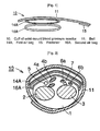
- Fig. 1 is a schematic view of a sectional structure of a cuff 10 of a wrist-mount blood pressure monitor along the longitudinal direction before mounting on the wrist in a preferred embodiment of the invention
- Fig. 2 is a sectional view showing the cuff 10 of a wrist-mount blood pressure monitor being mounted on the wrist
- Fig. 3 is a sectional view showing a state of pressing the wrist 1 by the cuff 10 of a wrist-mount blood pressure monitor
- Fig. 4 is a schematic view showing the principle of oppression of the wrist by using the cuff 10 of a wrist-mount blood pressure monitor.
- This cuff 10 of a wrist-mount blood pressure monitor comprises a first air bag 14A as a first inflatable portion used for collecting the air sent out from a pressurizing pump and oppressing an artery of the wrist, and a second air bag 16A as a second inflatable portion disposed between the first air bag 14A and the wrist, being made of a material of a higher stretchability than the material of the first air bag 14A.
- a band 11 is mounting means for mounting the first air bag 14A and second air bag 16A on the wrist, and a fastener 15 is used for winding around and fixing the band 11 on the wrist. In Fig. 1, air is not supplied into the air bags yet.
- the first air bag 14A when air is supplied, the first air bag 14A is inflated toward the wrist 1 side, and further the second air bag 16A, when air is supplied, is inflated to intrude mainly into the tendons or bones of the wrist 1.
- the second air bag 16A intrudes into the radius 2 and palmar long flexor tendon 4b.
- the second air bag 16A gets into the space between the radius 2 and palmar long flexor tendon 4b, and the radial artery 5 is sufficiently oppressed by the second air bag 16A.
- the second air bag 16A intrudes into the superficial flexor digital tendon 6a and ulnar carpal tendon 6b.
- the second air bag 16A gets into the space between the superficial flexor digital tendon 6a and ulnar carpal tendon 6b, so that the ulnar artery 7 is sufficiently oppressed by the second air bag 16A.
- both the first air bag 14A and second air bag 16A are inflated by supply of fluid, but since the second air bag 16A is made of a material of a higher stretchability than the material of the first air bag 14A, by inflation of the first air bag 14A, a specified pressure to the wrist 1 side is maintained.
- the second air bag 16A In a state in tight contact with the wrist 1, the second air bag 16A is inflated, and the second air bag 16A flexibly intrudes into the tendons or bones, so that the second air bag 16A gets into the space between the radius 2 and palmar long flexor tendon 4b, and hence the pressure from the first air bag 14A is applied to the wrist 1 which is kept in contact with the second air bag 16A regardless of the presence of the radius 2 and palmar long flexor tendon 4b of the wrist 1. Similarly, the second air bag 16A gets into the space between the superficial flexor digital tendon 6a and ulnar carpal tendon 6b. As a result, a sufficient cuff width W3 can be obtained.
- the air bags may be made of stretchable materials only.
- sufficient pressure is not applied in the direction for oppressing the wrist, but the air bags are largely inflated in the lateral direction, and the wrist cannot be oppressed sufficiently. Therefore, as mentioned above, it is important to combine the first air bag 14A as the first inflatable portion, and the second air bag 16A as the second inflatable portion made of a material of higher stretchability than the first air bag 14A.
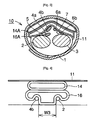
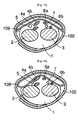
- FIG. 5 shows only the air bags of the cuff 10 of wrist-mount blood pressure monitor in a deflated state before supply of air
- Fig. 6 shows an inflated state after supply of air.
- the structure comprises a first air bag 14B as a first inflatable portion, and a second air bag 16B as a second inflatable portion positioned between the first air bag 14B and the wrist, being made of a material of a higher stretchability than the material of the first air bag 14B.
- a specific material of the first air bag 14B is vinyl chloride (a film thickness of about 0.3 mm).
- Other material usable for the first air bag 14B includes EVA (vinyl acetate; a film thickness of about 0.3 mm), and urethane (a film thickness of about 0.3 mm).
- a taper is formed of side walls 14a, 14b (accordion structure).
- the thickness of the first air bag 14B is about 1.2 mm.
- Specific materials for the second air bag 16B include thin films of silicone and latex, and the film thickness is about 0.3 mm.
- Other materials for the second air bag 16B include silicone and latex.
- air feed pipes 14c, 16c are provided, and a common air feed tube 17 is coupled to equalize the air pressure between the first air bag 14B and second air bag 16B.
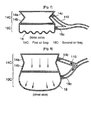
- FIG. 7 shows only the air bags in a state before supply of air
- Fig. 8 shows a state after supply of air.
- the structure comprises a first air bag 14C as a first inflatable portion, and a second air bag 16C as a second inflatable portion positioned between the first air bag 14C and the wrist, being made of a material of a higher stretchability than the material of the first air bag 14C.
- Specific materials and thickness of the first air bag 14C are same as in embodiment 1.
- a taper is formed of side walls 14a, 14b for encouraging inflation to the wrist side.
- Specific materials for the second air bag 16C are also same as in embodiment 1, but the structural feature of this embodiment is that the shape of the second air bag 16C at the wrist side is an undulated shape 18.
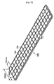
- Fig. 9 and Fig. 10 perspective development views showing the specific shape of the undulated shape 18 at the wrist 1 side of the second air bag 16C.
- Fig. 9 shows a first undulated shape 18A, in which (a) is a general perspective view, (b) is a sectional arrow view of X-X of (a), and (c) is a sectional view in inflated state.
- Fig. 10 is a general perspective view showing a second undulated shape 18B at the wrist 1 side of the second air bag 16C.
- the undulated shape 18A in Fig. 9 (a) comprises extruding portions 18a and dent portions 18b disposed alternately like waves along the longitudinal direction (see sectional view in Fig. 9 (b)), and in inflated state, as shown in Fig. 9 (c), all parts corresponding to the extruding portions 18a and dent portions 18b come to the outer side, so as to be inflated largely.
- the length of the extruding portions 18a is about 30 mm, the width is about 7.5 mm, and the height is about 2 mm.
- the undulated shape 18B shown in Fig. 10 comprises block-shaped extruding portions 18a disposed in a matrix, and dent portions 18b disposed between the extruding portions 18a like a lattice.
- the size of one extruding portion 18a is about 7.5 mm x 7.5 mm, and the height is about 2 mm.
- this undulated shape 18B too, same as in the undulated shape 18A, when inflated, all parts corresponding to the extruding portions 18a and dent portions 18b come to the outer side, so as to be inflated largely.
- the first air bags 14A, 14B, 14C, and second air bags 16A, 16B, 16C are provided in order to oppress both the radial artery 5 and ulnar artery 7 of the wrist, but a method of oppressing only the vicinity of the radial pedicular process is proposed by S. Mutsu et al. in "Analysis by finite element method about fitting position and size of cuff for local oppression in measurement of blood pressure by the wrist" (11th fall general meeting of Japan Society of ME). This paper, however shows or, teaches nothing about the technology of using first air bag and second air bag.
- Fig. 11 shows the structure of the cuff 10 of a wrist-mount blood pressure monitor being applied for oppressing only the vicinity of the radial pedicular process.
- the first air bag 14A by inflation of the first air bag 14A, a specified pressure to the wrist 1 side is assured, and the second air bag 16A is inflated in a state of tight contact with the wrist 1, and the second air bag 16A intrudes flexibly into the tendons or bones, so that the second air bag 16A gets into the space between the radius 2 and palmar long flexor tendon 4b, so that the radial artery 5 can be sufficiently oppressed.
- the first air bag and second air bag are composed as independent air bags, but they may be made of a single air bag as far as the region of the first air bag is inflated mainly toward the wrist 1 side when air is supplied and the region of the second air bag is inflated to intrude mainly into the tendons or bones of the wrist 1 when air is supplied.
- air is used as the fluid, but not limited to air, but other gas having similar properties may be used (for example, oxygen, carbon dioxide, helium). Not limited to gas, water or other liquid may be also used.
- gas gas, water or other liquid may be also used.
- an airtight structure must be employed in the fluid passage so as to avoid liquid leak.
- the pressure from the first inflatable portion is applied to the wrist which is kept in contact with the second inflatable portion regardless of the presence of tendons and bones of the wrist, and the artery of the wrist can be oppressed sufficiently.
- the problem of lack of oppression force of the artery is eliminated, and the blood pressure can be measured precisely by using a wrist-mount blood pressure monitor.
Landscapes
- Health & Medical Sciences (AREA)
- Life Sciences & Earth Sciences (AREA)
- Cardiology (AREA)
- Vascular Medicine (AREA)
- Engineering & Computer Science (AREA)
- Public Health (AREA)
- Biomedical Technology (AREA)
- Heart & Thoracic Surgery (AREA)
- Medical Informatics (AREA)
- Molecular Biology (AREA)
- Surgery (AREA)
- Animal Behavior & Ethology (AREA)
- General Health & Medical Sciences (AREA)
- Physics & Mathematics (AREA)
- Veterinary Medicine (AREA)
- Pathology (AREA)
- Biophysics (AREA)
- Physiology (AREA)
- Ophthalmology & Optometry (AREA)
- Dentistry (AREA)
- Measuring Pulse, Heart Rate, Blood Pressure Or Blood Flow (AREA)
Applications Claiming Priority (2)
| Application Number | Priority Date | Filing Date | Title |
|---|---|---|---|
| JP2001135955 | 2001-05-07 | ||
| JP2001135955 | 2001-05-07 |
Publications (3)
| Publication Number | Publication Date |
|---|---|
| EP1256313A2 true EP1256313A2 (de) | 2002-11-13 |
| EP1256313A3 EP1256313A3 (de) | 2002-11-27 |
| EP1256313B1 EP1256313B1 (de) | 2007-11-28 |
Family
ID=18983329
Family Applications (1)
| Application Number | Title | Priority Date | Filing Date |
|---|---|---|---|
| EP02009705A Expired - Lifetime EP1256313B1 (de) | 2001-05-07 | 2002-04-29 | Am Handgelenk zu tragende Manschette eines Blutdruckmessgeräts |
Country Status (4)
| Country | Link |
|---|---|
| US (1) | US6694821B2 (de) |
| EP (1) | EP1256313B1 (de) |
| CN (1) | CN1181786C (de) |
| DE (1) | DE60223747T2 (de) |
Cited By (6)
| Publication number | Priority date | Publication date | Assignee | Title |
|---|---|---|---|---|
| US6694821B2 (en) | 2001-05-07 | 2004-02-24 | Omron Corporation | Cuff of wrist-mount blood pressure monitor |
| WO2004047633A1 (en) * | 2002-11-25 | 2004-06-10 | Harry Louis Platt | Combined wrist blood pressure and ecg monitor |
| EP1525843A3 (de) * | 2003-10-24 | 2005-05-25 | Nihon Seimitsu Sokki Co., Ltd. | Sphygmomanometer und Innenkern dafür |
| WO2006114157A3 (de) * | 2005-04-28 | 2007-03-08 | Braun Gmbh | Blutdruckmessgerät |
| EP1958566A4 (de) * | 2005-11-30 | 2009-12-16 | Omron Healthcare Co Ltd | Blutdruckmessgerät für die genaue blutdruckmessung |
| WO2015060966A1 (en) * | 2013-10-25 | 2015-04-30 | Medtronic Vascular Inc. | Tissue compression device with pressure indicator |
Families Citing this family (47)
| Publication number | Priority date | Publication date | Assignee | Title |
|---|---|---|---|---|
| US6888041B1 (en) * | 1997-02-12 | 2005-05-03 | Quark Systems Co., Ltd. | Decomposition apparatus of organic compound, decomposition method thereof, excimer UV lamp and excimer emission apparatus |
| DE60328343D1 (de) | 2002-07-15 | 2009-08-27 | Terumo Corp | Blutstillende Vorrichtung mit aufblasbarem Ballon |
| JP3952957B2 (ja) * | 2003-01-22 | 2007-08-01 | オムロンヘルスケア株式会社 | 手首式血圧計用カフ |
| JP2004283320A (ja) * | 2003-03-20 | 2004-10-14 | Colin Medical Technology Corp | 二重カフ |
| BRPI0503972A (pt) * | 2004-09-09 | 2006-04-18 | Ricardo Rodriguez Aranciva | esfigmomanÈmetro aplicável a membros de diferentes medidas |
| US8454521B2 (en) * | 2004-09-10 | 2013-06-04 | Terumo Kabushiki Kaisha | Sphygmomanometer |
| USD526414S1 (en) | 2004-11-22 | 2006-08-08 | Medport, Llc | Blood pressure monitor |
| US20060111637A1 (en) * | 2004-11-23 | 2006-05-25 | Jacober Jeffrey M | Wrist-mount blood pressure monitor with auditory feature |
| US20060111636A1 (en) * | 2004-11-23 | 2006-05-25 | Jacober Jeffrey M | Wrist-mount blood pressure monitor |
| JP4595525B2 (ja) * | 2004-12-20 | 2010-12-08 | オムロンヘルスケア株式会社 | 血圧計用カフおよびこれを備えた血圧計 |
| JP4595526B2 (ja) * | 2004-12-20 | 2010-12-08 | オムロンヘルスケア株式会社 | 血圧計用カフおよび血圧計 |
| JP4470868B2 (ja) * | 2005-11-22 | 2010-06-02 | パナソニック電工株式会社 | 生体情報計測装置 |
| JP4325639B2 (ja) * | 2005-12-05 | 2009-09-02 | オムロンヘルスケア株式会社 | 血圧測定装置 |
| EP2029006B1 (de) * | 2006-05-30 | 2017-04-26 | Colin Dunlop | Blutdruckmonitor |
| TWM328632U (en) * | 2007-06-08 | 2008-03-11 | Mesure Technology Co Ltd | Sensitive patch, mounting belt device and wireless monitoring device |
| JP5223566B2 (ja) * | 2008-09-26 | 2013-06-26 | オムロンヘルスケア株式会社 | 血圧情報測定装置 |
| CN102198000B (zh) * | 2010-03-25 | 2013-08-28 | 吉易高科股份有限公司 | 高精确度血压计及血压量测方法 |
| JP2012200410A (ja) * | 2011-03-25 | 2012-10-22 | Omron Healthcare Co Ltd | 血圧情報測定装置用カフおよびこれを備えた血圧情報測定装置 |
| TWI459926B (zh) * | 2011-08-19 | 2014-11-11 | 中原大學 | Pulse pressure signal measurement system and its measurement method |
| US9028419B2 (en) * | 2011-08-29 | 2015-05-12 | Welch Allyn, Inc. | Blood pressure cuff |
| USD705428S1 (en) | 2012-08-29 | 2014-05-20 | Merit Medical Systems, Inc. | Medical compression bandage |
| USD705429S1 (en) | 2012-08-29 | 2014-05-20 | Merit Medical Systems, Inc. | Medical compression bandage |
| US10905361B2 (en) | 2013-05-06 | 2021-02-02 | Promedica Health System, Inc. | Radial check device |
| US9332994B2 (en) | 2013-07-12 | 2016-05-10 | Vasoinnovations, Inc. | Apparatus and method to stop bleeding |
| US10213214B2 (en) | 2013-07-12 | 2019-02-26 | Vasoinnovations, Inc. | Method to stop bleeding, with short hemostasis duration using a low dose of anticoagulant |
| US9308000B2 (en) | 2013-07-12 | 2016-04-12 | Vasoinnovations, Inc. | Method of transradial catheterization, device for ulnar artery compression, and method of use |
| US9668744B2 (en) | 2015-08-05 | 2017-06-06 | Vasoinnovations, Inc. | Apparatus and method to stop bleeding |
| US11564697B2 (en) | 2013-07-12 | 2023-01-31 | Vasoinnovations Inc. | Apparatus and method to stop bleeding |
| US10888334B2 (en) | 2013-07-12 | 2021-01-12 | Vasoinnovations Inc. | Apparatus and method to stop bleeding |
| US10342551B2 (en) | 2013-07-12 | 2019-07-09 | Vasoinnovations Inc. | Method to stop bleeding, with short hemostasis duration using a low dose of anticoagulant |
| US9949738B2 (en) | 2013-07-12 | 2018-04-24 | Vasoinnovations, Inc. | Method to stop bleeding, with short hemostasis duration using a low dose of anticoagulant |
| US10092297B2 (en) | 2014-04-25 | 2018-10-09 | Medtronic Vascular, Inc. | Tissue compression device with fixation and tension straps |
| JP6806669B2 (ja) * | 2015-04-07 | 2021-01-06 | テルモ株式会社 | 止血器具 |
| CN108024818B (zh) | 2015-09-03 | 2021-07-16 | 泰尔茂株式会社 | 止血器具 |
| JP6740232B2 (ja) * | 2015-09-03 | 2020-08-12 | テルモ株式会社 | 止血器具 |
| JP6772057B2 (ja) | 2016-12-28 | 2020-10-21 | オムロン株式会社 | 血圧計および血圧測定方法並びに機器 |
| JP6747332B2 (ja) * | 2017-02-16 | 2020-08-26 | オムロンヘルスケア株式会社 | 血圧情報測定装置 |
| US20180338693A1 (en) * | 2017-05-24 | 2018-11-29 | Edwards Lifesciences Corporation | Use of a multi-compartment bladder in a finger cuff |
| WO2020068626A1 (en) * | 2018-09-28 | 2020-04-02 | Jaichi Technologies Llc | Inflatable cuffs with controllable extensibility |
| JP7219086B2 (ja) * | 2018-12-27 | 2023-02-07 | オムロンヘルスケア株式会社 | 血圧計、血圧測定方法、およびプログラム |
| CA3132156A1 (en) * | 2019-03-01 | 2020-09-10 | Terumo Kabushiki Kaisha | Hemostasis devices with folded balloon assemblies |
| US12507901B2 (en) | 2020-07-14 | 2025-12-30 | Apple Inc. | Integrated flexible sensor for blood pressure measurements |
| US11744476B2 (en) | 2020-08-20 | 2023-09-05 | Apple Inc. | Blood pressure measurement using device with piezoelectric sensor |
| US12251204B2 (en) | 2021-02-03 | 2025-03-18 | Apple Inc. | Blood pressure monitoring system including a liquid filled sensor |
| US20220304700A1 (en) * | 2021-03-26 | 2022-09-29 | Terumo Medical Corporation | Hemostasis band with inflatable compartments and methods of using same |
| CN114767083B (zh) * | 2022-05-09 | 2025-11-04 | 西安力邦医疗电子有限公司 | 一种新型血压测量定位装置及应用 |
| CN115153472B (zh) * | 2022-07-26 | 2025-09-12 | 深圳市捷美瑞科技有限公司 | 血压采集组件、血压计及血压测量方法 |
Family Cites Families (12)
| Publication number | Priority date | Publication date | Assignee | Title |
|---|---|---|---|---|
| FR2568464B1 (fr) * | 1984-07-31 | 1988-07-22 | Mo Fiz Tekhn | Procede pour determiner l'etat du systeme cardiovasculaire et dispositif pour sa mise en oeuvre. |
| US5511551A (en) | 1993-03-15 | 1996-04-30 | Omron Corporation | Cuff for blood pressure meter |
| GB9507328D0 (en) * | 1995-04-08 | 1995-05-31 | Novamedix Ltd | A medical device |
| JPH11309119A (ja) * | 1998-04-27 | 1999-11-09 | Omron Corp | 血圧計用カフ |
| JP2000229070A (ja) * | 1999-02-12 | 2000-08-22 | Omron Corp | 血圧計用カフ |
| US6336901B1 (en) | 1998-04-27 | 2002-01-08 | Omron Corporation | Sphygmomanometer cuff achieving precise measurement of blood pressure |
| JP3243228B2 (ja) * | 1998-05-28 | 2002-01-07 | マイクロライフ システムズ エージー | 身体に挿入しない動脈血圧の測定装置 |
| JP3529287B2 (ja) | 1998-12-07 | 2004-05-24 | 日本電気株式会社 | 論理回路最適化方法 |
| DK1177762T3 (da) * | 1999-04-21 | 2013-01-14 | Jie Kan | Fremgangsmåde og apparatur til ikke-invasiv blodtryksmåling |
| JP3671746B2 (ja) * | 1999-06-11 | 2005-07-13 | 松下電工株式会社 | 血圧計 |
| JP3213296B2 (ja) * | 1999-11-01 | 2001-10-02 | 日本コーリン株式会社 | 脈波伝播速度情報測定装置 |
| DE60223747T2 (de) | 2001-05-07 | 2008-10-30 | Omron Healthcare Co., Ltd. | Am Handgelenk zu tragende Manschette eines Blutdruckmessgeräts |
-
2002
- 2002-04-29 DE DE60223747T patent/DE60223747T2/de not_active Expired - Lifetime
- 2002-04-29 EP EP02009705A patent/EP1256313B1/de not_active Expired - Lifetime
- 2002-05-01 US US10/135,847 patent/US6694821B2/en not_active Expired - Lifetime
- 2002-05-08 CN CNB021190631A patent/CN1181786C/zh not_active Expired - Lifetime
Cited By (14)
| Publication number | Priority date | Publication date | Assignee | Title |
|---|---|---|---|---|
| US6694821B2 (en) | 2001-05-07 | 2004-02-24 | Omron Corporation | Cuff of wrist-mount blood pressure monitor |
| WO2004047633A1 (en) * | 2002-11-25 | 2004-06-10 | Harry Louis Platt | Combined wrist blood pressure and ecg monitor |
| EP1525843A3 (de) * | 2003-10-24 | 2005-05-25 | Nihon Seimitsu Sokki Co., Ltd. | Sphygmomanometer und Innenkern dafür |
| US7374543B2 (en) | 2003-10-24 | 2008-05-20 | Nihon Seimitsu Sokki Co., Ltd. | Wrist sphygmomanometer and cuff spring for the same |
| US8292821B2 (en) | 2003-10-24 | 2012-10-23 | Nihon Seimitsu Sokki Co., Ltd. | Wrist sphygmomanometer and cuff spring for the same |
| WO2006114157A3 (de) * | 2005-04-28 | 2007-03-08 | Braun Gmbh | Blutdruckmessgerät |
| US7780605B2 (en) | 2005-11-30 | 2010-08-24 | Omron Healthcare Co., Ltd. | Blood pressure measuring apparatus enabling accurate blood pressure measurement |
| EP1958566A4 (de) * | 2005-11-30 | 2009-12-16 | Omron Healthcare Co Ltd | Blutdruckmessgerät für die genaue blutdruckmessung |
| WO2015060966A1 (en) * | 2013-10-25 | 2015-04-30 | Medtronic Vascular Inc. | Tissue compression device with pressure indicator |
| CN105682563A (zh) * | 2013-10-25 | 2016-06-15 | 美敦力瓦斯科尔勒公司 | 具有压力指示器的组织按压装置 |
| US9955978B2 (en) | 2013-10-25 | 2018-05-01 | Medtronic Vascular, Inc. | Tissue compression device with multi-chamber bladder |
| US10034671B2 (en) | 2013-10-25 | 2018-07-31 | Medtronic Vascular, Inc. | Tissue compression device with pressure indicator |
| CN105682563B (zh) * | 2013-10-25 | 2018-10-19 | 美敦力瓦斯科尔勒公司 | 具有压力指示器的组织按压装置 |
| US11172937B2 (en) | 2013-10-25 | 2021-11-16 | Medtronic Vascular, Inc. | Tissue compression device with pressure indicator |
Also Published As
| Publication number | Publication date |
|---|---|
| US20020170359A1 (en) | 2002-11-21 |
| CN1181786C (zh) | 2004-12-29 |
| CN1383783A (zh) | 2002-12-11 |
| EP1256313A3 (de) | 2002-11-27 |
| EP1256313B1 (de) | 2007-11-28 |
| DE60223747D1 (de) | 2008-01-10 |
| DE60223747T2 (de) | 2008-10-30 |
| US6694821B2 (en) | 2004-02-24 |
Similar Documents
| Publication | Publication Date | Title |
|---|---|---|
| US6694821B2 (en) | Cuff of wrist-mount blood pressure monitor | |
| AU759850B2 (en) | Pressure applicator devices particularly useful for non-invasive detection of medical conditions | |
| US6932773B2 (en) | Wrist type blood pressure meter cuff | |
| US5269312A (en) | Pressure pulse wave transmitting sheet used with pressure pulse wave sensor | |
| US6336901B1 (en) | Sphygmomanometer cuff achieving precise measurement of blood pressure | |
| US11925443B2 (en) | Blood pressure monitor, blood pressure measurement apparatus and blood pressure measurement method | |
| JP3671746B2 (ja) | 血圧計 | |
| JP2004503280A (ja) | 生命徴候をモニタする装置 | |
| WO2002080752A2 (en) | Non-invasive probe for detecting medical conditions | |
| US20200323446A1 (en) | Blood pressure measurement device | |
| TW200400021A (en) | Blood-pressure determining apparatus | |
| JP3922087B2 (ja) | 手首式血圧計用カフ | |
| US11647912B2 (en) | Blood pressure measuring device | |
| WO2019131238A1 (ja) | 血圧測定装置 | |
| EP1952759B1 (de) | Gerät zur messung von biologischen daten | |
| EP1338243A1 (de) | Blutdruckmessgerät und Gerät zum Messen eines Blutdruckindexes an oberen und unteren Gliedmassen | |
| WO2019131241A1 (ja) | 血圧測定装置 | |
| JP2004223035A (ja) | 脈波測定装置 | |
| CA2539420A1 (en) | Blood pressure monitor cuff and blood pressure monitor | |
| WO2020180039A2 (ko) | 혈압 측정 시스템 및 이를 이용한 혈압 측정 방법 | |
| JPH11318835A (ja) | 生体圧迫装置 | |
| US20210068684A1 (en) | Sensor module, method for manufacturing sensor module, and blood pressure measurement device | |
| WO2019131239A1 (ja) | 血圧測定装置 | |
| JP3591302B2 (ja) | 手首血圧計用カフ | |
| US11534073B2 (en) | Blood pressure measuring device |
Legal Events
| Date | Code | Title | Description |
|---|---|---|---|
| PUAI | Public reference made under article 153(3) epc to a published international application that has entered the european phase |
Free format text: ORIGINAL CODE: 0009012 |
|
| PUAL | Search report despatched |
Free format text: ORIGINAL CODE: 0009013 |
|
| AK | Designated contracting states |
Kind code of ref document: A2 Designated state(s): AT BE CH CY DE DK ES FI FR GB GR IE IT LI LU MC NL PT SE TR |
|
| AX | Request for extension of the european patent |
Free format text: AL;LT;LV;MK;RO;SI |
|
| AK | Designated contracting states |
Kind code of ref document: A3 Designated state(s): AT BE CH CY DE DK ES FI FR GB GR IE IT LI LU MC NL PT SE TR |
|
| AX | Request for extension of the european patent |
Free format text: AL;LT;LV;MK;RO;SI |
|
| 17P | Request for examination filed |
Effective date: 20030326 |
|
| AKX | Designation fees paid |
Designated state(s): DE FR GB IT |
|
| 17Q | First examination report despatched |
Effective date: 20030710 |
|
| RAP1 | Party data changed (applicant data changed or rights of an application transferred) |
Owner name: OMRON HEALTHCARE CO., LTD. |
|
| RAP1 | Party data changed (applicant data changed or rights of an application transferred) |
Owner name: OMRON HEALTHCARE CO., LTD. |
|
| GRAP | Despatch of communication of intention to grant a patent |
Free format text: ORIGINAL CODE: EPIDOSNIGR1 |
|
| GRAS | Grant fee paid |
Free format text: ORIGINAL CODE: EPIDOSNIGR3 |
|
| GRAA | (expected) grant |
Free format text: ORIGINAL CODE: 0009210 |
|
| RIN1 | Information on inventor provided before grant (corrected) |
Inventor name: TANAKA, TAKAHIDE C/O OMRON HEALTHCARE CO., LTD. Inventor name: SANO, YOSHIHIKO C/O OMRON HEALTHCARE CO., LTD. Inventor name: YAMAKOSHI, KEN-ICHI Inventor name: OKU, SHOJIRO C/O OMRON HEALTHCARE CO., LTD Inventor name: KATO, HIROYUKI C/O OMRON HEALTHCARE CO., LTD. |
|
| AK | Designated contracting states |
Kind code of ref document: B1 Designated state(s): DE FR GB IT |
|
| RIN1 | Information on inventor provided before grant (corrected) |
Inventor name: KATO, HIROYUKI C/O OMRON HEALTHCARE CO., LTD. Inventor name: TANAKA, TAKAHIDE C/O OMRON HEALTHCARE CO., LTD. Inventor name: OKU, SHOJIRO C/O OMRON HEALTHCARE CO., LTD Inventor name: YAMAKOSHI, KEN-ICHI Inventor name: SANO, YOSHIHIKO C/O OMRON HEALTHCARE CO., LTD. |
|
| REF | Corresponds to: |
Ref document number: 60223747 Country of ref document: DE Date of ref document: 20080110 Kind code of ref document: P |
|
| ET | Fr: translation filed | ||
| PGFP | Annual fee paid to national office [announced via postgrant information from national office to epo] |
Ref country code: IT Payment date: 20080422 Year of fee payment: 7 |
|
| PLBE | No opposition filed within time limit |
Free format text: ORIGINAL CODE: 0009261 |
|
| STAA | Information on the status of an ep patent application or granted ep patent |
Free format text: STATUS: NO OPPOSITION FILED WITHIN TIME LIMIT |
|
| 26N | No opposition filed |
Effective date: 20080829 |
|
| PGFP | Annual fee paid to national office [announced via postgrant information from national office to epo] |
Ref country code: FR Payment date: 20080414 Year of fee payment: 7 |
|
| PGFP | Annual fee paid to national office [announced via postgrant information from national office to epo] |
Ref country code: GB Payment date: 20080414 Year of fee payment: 7 |
|
| GBPC | Gb: european patent ceased through non-payment of renewal fee |
Effective date: 20090429 |
|
| REG | Reference to a national code |
Ref country code: FR Ref legal event code: ST Effective date: 20091231 |
|
| PG25 | Lapsed in a contracting state [announced via postgrant information from national office to epo] |
Ref country code: GB Free format text: LAPSE BECAUSE OF NON-PAYMENT OF DUE FEES Effective date: 20090429 Ref country code: FR Free format text: LAPSE BECAUSE OF NON-PAYMENT OF DUE FEES Effective date: 20091222 |
|
| PG25 | Lapsed in a contracting state [announced via postgrant information from national office to epo] |
Ref country code: IT Free format text: LAPSE BECAUSE OF NON-PAYMENT OF DUE FEES Effective date: 20090429 |
|
| REG | Reference to a national code |
Ref country code: DE Ref legal event code: R082 Ref document number: 60223747 Country of ref document: DE Representative=s name: KILIAN KILIAN & PARTNER MBB PATENTANWAELTE, DE Ref country code: DE Ref legal event code: R082 Ref document number: 60223747 Country of ref document: DE Representative=s name: KILIAN KILIAN & PARTNER, DE |
|
| PGFP | Annual fee paid to national office [announced via postgrant information from national office to epo] |
Ref country code: DE Payment date: 20210429 Year of fee payment: 20 |
|
| REG | Reference to a national code |
Ref country code: DE Ref legal event code: R071 Ref document number: 60223747 Country of ref document: DE |