EP1254366B1 - Elektrochemischer sensor zur bestimmung von peressigsäure in wässerigen lösungen mittels pulsamperometrischen-verfahren - Google Patents
Elektrochemischer sensor zur bestimmung von peressigsäure in wässerigen lösungen mittels pulsamperometrischen-verfahren Download PDFInfo
- Publication number
- EP1254366B1 EP1254366B1 EP01907053A EP01907053A EP1254366B1 EP 1254366 B1 EP1254366 B1 EP 1254366B1 EP 01907053 A EP01907053 A EP 01907053A EP 01907053 A EP01907053 A EP 01907053A EP 1254366 B1 EP1254366 B1 EP 1254366B1
- Authority
- EP
- European Patent Office
- Prior art keywords
- peracetic acid
- solution
- electrode
- read voltage
- further characterized
- Prior art date
- Legal status (The legal status is an assumption and is not a legal conclusion. Google has not performed a legal analysis and makes no representation as to the accuracy of the status listed.)
- Expired - Lifetime
Links
- KFSLWBXXFJQRDL-UHFFFAOYSA-N Peracetic acid Chemical compound CC(=O)OO KFSLWBXXFJQRDL-UHFFFAOYSA-N 0.000 title claims abstract description 248
- 238000004082 amperometric method Methods 0.000 title description 3
- 239000007864 aqueous solution Substances 0.000 title 1
- 238000011895 specific detection Methods 0.000 title 1
- MHAJPDPJQMAIIY-UHFFFAOYSA-N Hydrogen peroxide Chemical compound OO MHAJPDPJQMAIIY-UHFFFAOYSA-N 0.000 claims abstract description 68
- 238000001514 detection method Methods 0.000 claims abstract description 12
- 230000001419 dependent effect Effects 0.000 claims abstract description 9
- 238000000034 method Methods 0.000 claims description 29
- 238000005259 measurement Methods 0.000 claims description 25
- OKTJSMMVPCPJKN-UHFFFAOYSA-N Carbon Chemical compound [C] OKTJSMMVPCPJKN-UHFFFAOYSA-N 0.000 claims description 24
- 229910052799 carbon Inorganic materials 0.000 claims description 15
- 238000005202 decontamination Methods 0.000 claims description 14
- 229910021607 Silver chloride Inorganic materials 0.000 claims description 11
- HKZLPVFGJNLROG-UHFFFAOYSA-M silver monochloride Chemical compound [Cl-].[Ag+] HKZLPVFGJNLROG-UHFFFAOYSA-M 0.000 claims description 11
- 229910002804 graphite Inorganic materials 0.000 claims description 10
- 239000010439 graphite Substances 0.000 claims description 10
- 238000009792 diffusion process Methods 0.000 claims description 7
- 229910052709 silver Inorganic materials 0.000 claims description 7
- 239000004332 silver Substances 0.000 claims description 7
- 238000011282 treatment Methods 0.000 claims description 7
- 239000000872 buffer Substances 0.000 claims description 5
- 230000000670 limiting effect Effects 0.000 claims description 3
- 238000011049 filling Methods 0.000 claims description 2
- 239000000080 wetting agent Substances 0.000 claims description 2
- 230000003750 conditioning effect Effects 0.000 claims 1
- 230000011664 signaling Effects 0.000 claims 1
- 238000004659 sterilization and disinfection Methods 0.000 abstract description 24
- 239000000243 solution Substances 0.000 description 67
- 239000000523 sample Substances 0.000 description 39
- 239000012530 fluid Substances 0.000 description 22
- XLYOFNOQVPJJNP-UHFFFAOYSA-N water Substances O XLYOFNOQVPJJNP-UHFFFAOYSA-N 0.000 description 21
- 230000003588 decontaminative effect Effects 0.000 description 12
- 230000001954 sterilising effect Effects 0.000 description 12
- 239000003792 electrolyte Substances 0.000 description 9
- 239000012141 concentrate Substances 0.000 description 8
- 239000007788 liquid Substances 0.000 description 8
- 241000894007 species Species 0.000 description 8
- 230000003139 buffering effect Effects 0.000 description 7
- 238000012544 monitoring process Methods 0.000 description 7
- 238000004140 cleaning Methods 0.000 description 6
- 238000005260 corrosion Methods 0.000 description 6
- 230000007797 corrosion Effects 0.000 description 6
- 238000002484 cyclic voltammetry Methods 0.000 description 5
- 239000007772 electrode material Substances 0.000 description 5
- 229910021397 glassy carbon Inorganic materials 0.000 description 5
- 239000003112 inhibitor Substances 0.000 description 5
- 230000001590 oxidative effect Effects 0.000 description 5
- 239000000126 substance Substances 0.000 description 5
- 230000000845 anti-microbial effect Effects 0.000 description 4
- 239000004599 antimicrobial Substances 0.000 description 4
- 230000008901 benefit Effects 0.000 description 4
- 239000003153 chemical reaction reagent Substances 0.000 description 4
- 230000000694 effects Effects 0.000 description 4
- -1 peroxide ions Chemical class 0.000 description 4
- 230000008569 process Effects 0.000 description 4
- 239000000758 substrate Substances 0.000 description 4
- QTBSBXVTEAMEQO-UHFFFAOYSA-N Acetic acid Chemical compound CC(O)=O QTBSBXVTEAMEQO-UHFFFAOYSA-N 0.000 description 3
- 239000007853 buffer solution Substances 0.000 description 3
- 238000006243 chemical reaction Methods 0.000 description 3
- 239000013626 chemical specie Substances 0.000 description 3
- PCHJSUWPFVWCPO-UHFFFAOYSA-N gold Chemical compound [Au] PCHJSUWPFVWCPO-UHFFFAOYSA-N 0.000 description 3
- 239000000976 ink Substances 0.000 description 3
- 239000000463 material Substances 0.000 description 3
- VNWKTOKETHGBQD-UHFFFAOYSA-N methane Chemical compound C VNWKTOKETHGBQD-UHFFFAOYSA-N 0.000 description 3
- 244000005700 microbiome Species 0.000 description 3
- 238000002156 mixing Methods 0.000 description 3
- 230000037361 pathway Effects 0.000 description 3
- 238000005070 sampling Methods 0.000 description 3
- RZVAJINKPMORJF-UHFFFAOYSA-N Acetaminophen Chemical compound CC(=O)NC1=CC=C(O)C=C1 RZVAJINKPMORJF-UHFFFAOYSA-N 0.000 description 2
- 239000002253 acid Substances 0.000 description 2
- 239000008364 bulk solution Substances 0.000 description 2
- 230000015556 catabolic process Effects 0.000 description 2
- 239000000919 ceramic Substances 0.000 description 2
- 150000001875 compounds Chemical class 0.000 description 2
- 238000006731 degradation reaction Methods 0.000 description 2
- 238000010586 diagram Methods 0.000 description 2
- 238000007599 discharging Methods 0.000 description 2
- 229910052737 gold Inorganic materials 0.000 description 2
- 239000010931 gold Substances 0.000 description 2
- 238000009413 insulation Methods 0.000 description 2
- 239000012528 membrane Substances 0.000 description 2
- 239000000203 mixture Substances 0.000 description 2
- 238000001208 nuclear magnetic resonance pulse sequence Methods 0.000 description 2
- 230000003647 oxidation Effects 0.000 description 2
- 238000007254 oxidation reaction Methods 0.000 description 2
- 150000004965 peroxy acids Chemical class 0.000 description 2
- BASFCYQUMIYNBI-UHFFFAOYSA-N platinum Chemical compound [Pt] BASFCYQUMIYNBI-UHFFFAOYSA-N 0.000 description 2
- 239000002243 precursor Substances 0.000 description 2
- 238000012545 processing Methods 0.000 description 2
- 238000004730 pulsed amperometry Methods 0.000 description 2
- 230000002829 reductive effect Effects 0.000 description 2
- 238000011012 sanitization Methods 0.000 description 2
- 230000035945 sensitivity Effects 0.000 description 2
- 239000010865 sewage Substances 0.000 description 2
- 239000007921 spray Substances 0.000 description 2
- 229910001220 stainless steel Inorganic materials 0.000 description 2
- 239000010935 stainless steel Substances 0.000 description 2
- 238000004448 titration Methods 0.000 description 2
- 238000001075 voltammogram Methods 0.000 description 2
- 239000002699 waste material Substances 0.000 description 2
- BSYNRYMUTXBXSQ-UHFFFAOYSA-N Aspirin Chemical compound CC(=O)OC1=CC=CC=C1C(O)=O BSYNRYMUTXBXSQ-UHFFFAOYSA-N 0.000 description 1
- 239000004215 Carbon black (E152) Substances 0.000 description 1
- MYMOFIZGZYHOMD-UHFFFAOYSA-N Dioxygen Chemical group O=O MYMOFIZGZYHOMD-UHFFFAOYSA-N 0.000 description 1
- UFHFLCQGNIYNRP-UHFFFAOYSA-N Hydrogen Chemical compound [H][H] UFHFLCQGNIYNRP-UHFFFAOYSA-N 0.000 description 1
- 102000003992 Peroxidases Human genes 0.000 description 1
- BQCADISMDOOEFD-UHFFFAOYSA-N Silver Chemical compound [Ag] BQCADISMDOOEFD-UHFFFAOYSA-N 0.000 description 1
- 229910000831 Steel Inorganic materials 0.000 description 1
- RTAQQCXQSZGOHL-UHFFFAOYSA-N Titanium Chemical compound [Ti] RTAQQCXQSZGOHL-UHFFFAOYSA-N 0.000 description 1
- 229960001138 acetylsalicylic acid Drugs 0.000 description 1
- 230000003466 anti-cipated effect Effects 0.000 description 1
- 230000015572 biosynthetic process Effects 0.000 description 1
- 238000004061 bleaching Methods 0.000 description 1
- 230000000903 blocking effect Effects 0.000 description 1
- 239000008280 blood Substances 0.000 description 1
- 210000004369 blood Anatomy 0.000 description 1
- 239000008366 buffered solution Substances 0.000 description 1
- 239000003575 carbonaceous material Substances 0.000 description 1
- 239000002738 chelating agent Substances 0.000 description 1
- 239000007795 chemical reaction product Substances 0.000 description 1
- 238000004891 communication Methods 0.000 description 1
- 230000001010 compromised effect Effects 0.000 description 1
- 239000004020 conductor Substances 0.000 description 1
- 238000011109 contamination Methods 0.000 description 1
- 238000001816 cooling Methods 0.000 description 1
- 230000002596 correlated effect Effects 0.000 description 1
- 230000000875 corresponding effect Effects 0.000 description 1
- 238000000354 decomposition reaction Methods 0.000 description 1
- 230000007423 decrease Effects 0.000 description 1
- 230000001934 delay Effects 0.000 description 1
- 239000000645 desinfectant Substances 0.000 description 1
- 230000000249 desinfective effect Effects 0.000 description 1
- 239000003599 detergent Substances 0.000 description 1
- 238000007865 diluting Methods 0.000 description 1
- 239000012153 distilled water Substances 0.000 description 1
- 230000005611 electricity Effects 0.000 description 1
- 238000000835 electrochemical detection Methods 0.000 description 1
- 238000003487 electrochemical reaction Methods 0.000 description 1
- 239000008151 electrolyte solution Substances 0.000 description 1
- 238000005516 engineering process Methods 0.000 description 1
- 238000011067 equilibration Methods 0.000 description 1
- KEUKAQNPUBYCIC-UHFFFAOYSA-N ethaneperoxoic acid;hydrogen peroxide Chemical compound OO.CC(=O)OO KEUKAQNPUBYCIC-UHFFFAOYSA-N 0.000 description 1
- 239000007789 gas Substances 0.000 description 1
- 229910001385 heavy metal Inorganic materials 0.000 description 1
- 229930195733 hydrocarbon Natural products 0.000 description 1
- 150000002430 hydrocarbons Chemical group 0.000 description 1
- 230000036512 infertility Effects 0.000 description 1
- 238000003780 insertion Methods 0.000 description 1
- 230000037431 insertion Effects 0.000 description 1
- 239000011810 insulating material Substances 0.000 description 1
- 230000002452 interceptive effect Effects 0.000 description 1
- 150000002500 ions Chemical class 0.000 description 1
- 230000002045 lasting effect Effects 0.000 description 1
- 230000007246 mechanism Effects 0.000 description 1
- 238000001465 metallisation Methods 0.000 description 1
- 230000007935 neutral effect Effects 0.000 description 1
- 239000012476 oxidizable substance Substances 0.000 description 1
- 238000004806 packaging method and process Methods 0.000 description 1
- 229960005489 paracetamol Drugs 0.000 description 1
- 239000002245 particle Substances 0.000 description 1
- 108040007629 peroxidase activity proteins Proteins 0.000 description 1
- 125000000864 peroxy group Chemical group O(O*)* 0.000 description 1
- 229910052697 platinum Inorganic materials 0.000 description 1
- 238000009428 plumbing Methods 0.000 description 1
- 238000001556 precipitation Methods 0.000 description 1
- 238000007639 printing Methods 0.000 description 1
- 230000009467 reduction Effects 0.000 description 1
- 230000001105 regulatory effect Effects 0.000 description 1
- 230000004044 response Effects 0.000 description 1
- 230000000717 retained effect Effects 0.000 description 1
- 229960001922 sodium perborate Drugs 0.000 description 1
- YKLJGMBLPUQQOI-UHFFFAOYSA-M sodium;oxidooxy(oxo)borane Chemical compound [Na+].[O-]OB=O YKLJGMBLPUQQOI-UHFFFAOYSA-M 0.000 description 1
- 239000007787 solid Substances 0.000 description 1
- 238000004365 square wave voltammetry Methods 0.000 description 1
- 239000010959 steel Substances 0.000 description 1
- 239000004094 surface-active agent Substances 0.000 description 1
- 239000008399 tap water Substances 0.000 description 1
- 235000020679 tap water Nutrition 0.000 description 1
- 229910052719 titanium Inorganic materials 0.000 description 1
- 239000010936 titanium Substances 0.000 description 1
Images


Classifications
-
- G—PHYSICS
- G01—MEASURING; TESTING
- G01N—INVESTIGATING OR ANALYSING MATERIALS BY DETERMINING THEIR CHEMICAL OR PHYSICAL PROPERTIES
- G01N27/00—Investigating or analysing materials by the use of electric, electrochemical, or magnetic means
- G01N27/26—Investigating or analysing materials by the use of electric, electrochemical, or magnetic means by investigating electrochemical variables; by using electrolysis or electrophoresis
- G01N27/403—Cells and electrode assemblies
- G01N27/404—Cells with anode, cathode and cell electrolyte on the same side of a permeable membrane which separates them from the sample fluid, e.g. Clark-type oxygen sensors
- G01N27/4045—Cells with anode, cathode and cell electrolyte on the same side of a permeable membrane which separates them from the sample fluid, e.g. Clark-type oxygen sensors for gases other than oxygen
-
- G—PHYSICS
- G01—MEASURING; TESTING
- G01N—INVESTIGATING OR ANALYSING MATERIALS BY DETERMINING THEIR CHEMICAL OR PHYSICAL PROPERTIES
- G01N27/00—Investigating or analysing materials by the use of electric, electrochemical, or magnetic means
- G01N27/26—Investigating or analysing materials by the use of electric, electrochemical, or magnetic means by investigating electrochemical variables; by using electrolysis or electrophoresis
- G01N27/416—Systems
- G01N27/49—Systems involving the determination of the current at a single specific value, or small range of values, of applied voltage for producing selective measurement of one or more particular ionic species
Definitions
- peracetic acid precursors are typically mixed with water and other chemicals in order to create a sterilant solution. Items to be sterilized or disinfected are then immersed in the sterilant. Decontaminated items are then rinsed to remove traces of the acid and other cleaning chemicals, before use. To ensure effective sterilization or disinfection within a preselected period of time, the concentration of peracetic acid is maintained above a selected minimum effective level. Disinfection is typically carried out at lower concentrations of peracetic acid than for sterilization. When the peracetic acid concentration is at or above the minimum effective level, complete sterilization or disinfection is expected.
- the peracetic acid tends to decompose over time, it is valuable to monitor the sterilant periodically to determine the level of peracetic acid.
- the level can be compared against preselected minimum levels, used to adjust contact time, used to control concentration, or the like.
- the sterilant will remain at or above the minimum effective concentration.
- differences in the temperature of the sterilant, the quantity of items sterilized or disinfected, and the degree and nature of contamination of the items all result in considerable variations in the degradation of the sterilant.
- storage conditions and duration sometimes lead to degradation of the peracetic acid precursors before use.
- European Patent Application EP 0 333 246 A discloses an electrochemical sensor for detection of oxidizable or reducible chemical species using an amperometric method in which a fixed potential is maintained between a reference and a working electrode. The current at the working electrode is used to determine the concentration of peracetic acid. Other species present, however, influence the current flowing, and hence the accuracy of the results.
- Teske U.S. Patent No. 5,503,720, discloses a process for the determination of reducible or oxidizable substances, such as peracetic acid in sewage waste.
- the process uses potentiostatic amperometry to detect peracetic acid concentrations.
- the technique depends on the achievement of a steady state, which frequently takes several hours.
- U.S. 5,873,990 discloses a handheld device for measurement of heavy metal ions and other species in blood. Amperometric measurements of hydrogen peroxide are made with a colloidal gold/peroxidase sensor while square wave voltammetry and a carbon electrode are used for monitoring acetaminophen.
- the present invention provides a new and improved method for the selective detection of peracetic acid, which overcomes the above-referenced problems and others.
- a method of detecting peracetic acid in a solution which also contains hydrogen peroxide comprises disposing a carbon working electrode, a reference electrode, and optionally a counter electrode in the solution to be tested, selectively pulsing a read voltage to the working electrode, and detecting current flowing between either the working electrode and the reference electrode or the working electrode the counter electrode, where present.
- the read voltage is selected such that the current flowing is dependent on a concentration of peracetic 'acid and substantially independent of a concentration of the hydrogen peroxide in the solution and is in the range of -0.5 to -1.4 volts, relative to a silver/silver chloride reference electrode.
- the detected current flow is converted into an indication of the concentration of the peracetic acid in the solution.
- One advantage of one embodiment of the present invention is that it enables the peracetic acid concentration of a sterilizing or disinfecting solution to be determined rapidly, (i.e., in less than one minute) and without interference by other oxidizing species present in the solution.
- the invention may take form in various components and arrangements of components, and in various steps and arrangements of steps.
- the drawings are only for purposes of illustrating a preferred embodiment and are not to be construed as limiting the invention.
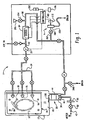
- a peracetic acid monitoring system or sensor A measures peracetic acid concentrations in the presence of hydrogen peroxide.
- the monitoring system will be described with reference to an automated liquid decontamination apparatus 1 which sequentially cleans items, such as endoscopes or other medical, dental, and pharmaceutical devices, and the like, and then sanitizes, sterilizes, or disinfects them with a decontaminant solution which contains peracetic acid. It should be appreciated, however that the monitoring system is also applicable to the measurement of peracetic acid concentrations in other treatment systems and peracetic acid-containing liquids.
- decontamination and other terms relating to decontaminating will be used herein to describe sanitizing, sterilization, disinfection, and other antimicrobial treatments which are designed to destroy microorganisms contaminating the items.
- the system 1 includes a decontamination cabinet 10 which defines an interior decontamination chamber 12. Items to be sterilized, disinfected, sanitized, or otherwise microbially decontaminated are loaded into the decontamination chamber through an opening in a front wall 13 of the cabinet, illustrated as closed by a door 14. Within the chamber, several spray jets or nozzles 16 spray a decontaminant solution over the items. Optionally, in the case of instruments with lumens, or other internal passages, some of the nozzles act as fluid ports 18 which are configured for interconnection with internal passages of the endoscopes and other objects with lumens, for supplying decontaminant solution and other liquids to the internal passages.
- a collection tank or sump 20 forms the base of the cabinet 10 and receives the sprayed decontaminant solution as it drips off the items.
- a high pressure pump 22 delivers the decontaminant solution under pressure to the nozzles 16 and fluid ports 18 through a fluid distribution system or manifold 24.
- the cup holds a cleaning concentrate in a first compartment.
- a second compartment holds pretreatment components, such as buffers for adjusting the pH, surfactants, chelating agents, and corrosion inhibitors for protecting the components of the system and items to be decontaminated from corrosion by the decontaminant.
- a decontaminant such as concentrated liquid peracetic acid solution (or reagents that react to form it) is held in a third compartment.
- a cup cutter 46 or other suitable opening member, is positioned at the base of the well 34 for opening selected compartments of the cup, in sequence.
- the water used for diluting the cleaner concentrate and decontaminant may be tap water or treated water, such as distilled water, filtered water, microbe free water, or the like.
- the quantity of water entering the system is regulated to provide a decontaminant solution of a desired concentration in the decontamination chamber 12.
- the water is preferably passed through a microporous filter 50 in the water inlet line 42 which filters out particles of dirt and microorganisms.
- a valve 52 in the water inlet 42 closes when the selected quantity of water has been admitted.
- a fluid supply pathway 60 connects the well 40, the pump 22, and the fluid distribution system 24.
- a heater 64 situated in the fluid supply pathway 60, heats the decontaminant solution and optionally the cleaning solution and rinse liquid to a preferred temperature(s) for effective cleaning, decontamination, and rinsing. A temperature of about 50-60°C is preferred for sterilization with peracetic acid.
- the pathway 60 returns the sprayed decontaminant solution from the sump 20 to the manifold 24, and thence to the nozzles 16 and the fluid ports 18 via a recirculation valve 68. At least a portion of the sprayed decontaminant solution is directed through the well 34 before being returned to the decontamination chamber. This ensures thorough mixing of the concentrated decontaminant and other components with the solution before returning the decontaminant solution to the nozzles 16, 18.
- the peracetic acid monitoring system A detects the concentration of peracetic acid passing through the fluid lines.
- FIGURE 1 shows the system connected with the line 60. It should be appreciated, however, that the sensor is also conveniently connected with or disposed in any of the fluid flow lines of the system or simply in a bath of decontaminant solution.
- a computer control system 80 controls the operation of the peracetic acid monitoring system A . Preferably, the control system also controls the operation of other elements of the system 1 , including the introduction of the cleaner concentrate, the peroxy concentrate, and other reagents as well as the pump 22, the heater 64, the valves 52, 68 and the like.
- the control system 80 may control one or more additional systems 1, if desired.
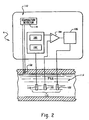
- the system A for selective detection of peracetic acid includes an electrode system 110, and an amperometric controller 112.
- the controller 112 both applies voltages and detects current flows in the system A .
- the controller is shown as a single unit in FIGURE 2, it should be understood that a combination of pieces of electrochemical equipment generally known in the art which serves these functions is also contemplated.
- the electrode system 110 can be a two or three electrode system. In a three electrode system it includes a working or sensing electrode 118, a reference electrode 120, and a counter electrode 122. In a two electrode system, the counter electrode is eliminated in favor of a reference electrode which also serves the functions of the counter electrode, although with some loss in stability of the system to be expected.
- the reference electrode produces a constant electrical potential (or base potential) and assures a stable reference potential when the current density flowing through the electrode is small.
- Suitable reference electrodes 120 include silver/silver chloride electrodes.
- the working electrode is formed from a carbon material and is an electroactive for peracetic acid.
- Other features of good working electrode materials include minimal to no consumption of the electrode material during operation of the sensor, useful working potential range covering the detection potential of peracetic acid, provision of a high signal to background noise ratio for peracetic acid, and a low sensitivity to interfering substances, such as hydrogen peroxide.
- Carbon is an effective electroactive for peracetic acid and is highly selective for peracetic acid in the presence of hydrogen peroxide.
- Carbon electrodes are also relatively resistant to peracetic acid, giving them a longer useful life. Crystalline forms of carbon, such as graphite, provide effective working electrodes for measurements in the diffusion limited region.
- the counter electrode 122 is preferably formed from an inert conductive material, such as carbon. Alternatively, suitable counter electrodes are formed from silver, gold, platinum, or titanium. The external circuit is closed between the working electrode and the counter electrode.
- a substrate 124 preferably formed from an inert polymeric or ceramic sheet, supports the electrode system 110 to form a disposable probe 125.
- Electric leads 126 electrically connect the electrodes and the controller 112 through connecting points 128.
- the sensor probe also includes an insulation layer 130 which covers the substrate and the leads around the connection points. The insulation layer inhibits the leads from participating in the electrochemical reactions.
- a thermistor 132 detects the temperature of the sample in the region around the probe.
- the sensor probe 125 is preferably constructed by photolithographic metalization or thick film printing technology, although other methods of probe formation are also contemplated.
- components of the sensor including electrodes, electrical connection points and electrical leads are all laid down on the substrate. Materials for the electrodes and connection points are separately dispersed in inks and printed onto the substrate. The inks are cured, for example, by heat, UV light, or the like. The probes produced are inexpensive and thus are suited to single use. Additionally, such probes can be used without prior calibration.
- the electrode materials are selected so that they will not become disbonded when immersed in a peracetic acid solution at temperatures between around 25°C and 75°C. The choice of ink also affects the conductivity to some degree.
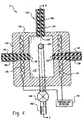
- the chamber 114' and housing 150 are configured such that the thermal mass of the housing is substantially greater than the volume of the decontaminant solution to be sampled.
- the internal volume of the chamber is preferably about 10-15 ml or less.
- One or more thermal elements 176 within the walls 156 of the housing, maintains the housing at a stable temperature, and thereby the sampled fluid.
- the sample is heated to a measurement temperature only slightly above the maximum temperature expected in the circulating fluid. This allows the sample to reach the measurement temperature very quickly. For example, if the decontamination portion of the cycle operates at about 50-55°C, the walls are preferably maintained at about 60°C.
- the sample may be cooled by cooling elements, such as by Peltier elements, to achieve an optimum measuring temperature.
- the valve 168 opens and allows the sampled fluid to flow into the chamber.
- the valve 168 remains open for sufficient time to allow the sampled fluid to flush the contents of the chamber through the overflow and replace the contents with freshly sampled fluid.
- the drain valve may be opened to allow the prior sample to flow from the chamber.
- the valve is then closed and the chamber filled with a rinsing sample, which may be the same as the measurement sample.
- the rinsing sample is then drained and the chamber filled with a sample for measurement.
- the pump 22 pressurizes the circulating decontaminant to about 70 psi.
- a flush and fill period of around three seconds is sufficient to fill the chamber with a fresh sample of decontaminant solution.
- the valve is then closed and the sample is held within the chamber for sufficient time to equilibrate the temperature and for the sampled fluid to become quiescent.
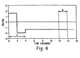
- a pulsed voltage sequence is applied to the electrodes, resulting in the generation of an electrical current which is correlated to the concentration of peracetic acid in the sample.
- the sampling and measurement steps are repeated, preferably every one to two minutes, to ensure that the peracetic acid concentration does not drop below a minimum acceptable level.
- the amperometric controller 112 includes a voltage regulator 180 which applies a reference voltage (relative to the potential generated by the reference electrode) between the reference electrode 120 and the working electrode 118 of the embodiment of either FIGURE 3 or FIGURES 4 and 5.
- a voltage pulser 182 superimposes a read voltage between the reference and working electrodes in short pulses. The current flowing through the counter electrode is the same as that of the working electrode.
- the controller 112 also includes a current monitor 186 which detects the current flowing between the working and counter electrodes.
- the current measured is dependent on both the peracetic acid concentration and the concentration of other oxidizing species, such as hydrogen peroxide, in the solution tested.
- the respective contributions of each of these components to the overall current measured is dependent on the selected read voltage.
- the hydrogen peroxide or other oxidizing species present
- the current measured is virtually independent of the concentration of hydrogen peroxide and shows a linear relationship with peracetic acid concentration.
- positive (+1.5 to +2.8V vs an Ag/AgCl reference electrode) and negative (-1.8 to -2.5 V vs the Ag/AgCl reference electrode) pulses e.g., as a square or sine wave
- positive and negative pulses are generally effective.
- the pulse sequence of FIGURE 6 is repeated a plurality of times during the antimicrobial stage of the cycle, each time with a new sample of the circulated solution. Any residue build-up at the end of cycle is electrochemically removed at the beginning of the next cycle. More specifically, after the last measurement, liquid is retained in the electrolytic cell either by retaining the last sample or by filling the cell with rinse water in the subsequent rinse stage.
- the optimum read voltage may not be achievable in the electrochemical system due to background noise.
- the current output tends to be masked by background noise and therefore measurement of very low peracetic acid concentrations, in particular, may be difficult.
- the choice of a preferred read voltage is dependent on the likely concentrations of peracetic acid to be measured, the ratio of peracetic acid to hydrogen peroxide, and the degree of background noise in the system. Using a carbon electrode pushes the optimum read voltage away from the background noise region (-20mV).
- the current output increases with temperature.
- the heated housing brings the temperature of the sample to a constant temperature for measurements to be made.
- the working electrode surface area is significantly smaller than that of the counter electrode.
- the current flow generated for a given peracetic acid concentration is limited by the working electrode surface area.
- the counter electrode has a larger surface area than 'the working electrode to avoid saturation of the electrode with electrons and a loss of the linear relationship between peracetic acid concentration and current flow at higher peracetic acid concentrations.
- the read voltage is pulsed between the reference and working electrodes (and hence to the counter electrode) at a fixed rate.
- a preferred duration of read voltage is about 10 seconds. Because of double layer discharging and rate limiting diffusion effects, the current output decreases asymptotically with time, eventually reaching a plateau region in which the current output is relatively constant with time. A sample time of around 5-15 seconds allows such steady state conditions to be established.
- the controller 112 then detects the current output, from which the peracetic acid concentration is determined. Between each sampling period, the working electrode is preconditioned again, as described.
- the working electrode When peracetic acid is present in the sample, the working electrode becomes enriched with electrons when the sensing pulse is applied. This excess of electrons will tend to cause the peracetic acid molecules in the vicinity of the electrode to become reduced (i.e., accept electrons from the surface of the electrode.) The movement of electrons from the electrode into the solution via this mechanism produces the electrical current that can be measured.
- the peracetic acid sensor A measures this diffusion limited current.
- the decontaminant solution contains a buffering system which acts as an electrolyte. When a voltage is applied, a small current will flow due to the electrical conductivity of the electrolyte. In addition, when chemical species are present that are susceptible to electrochemical conversion, an additional electrical current will be produced due to electrochemical conversions at the surfaces of the electrodes.
- the computer control system 80 signals an alarm 202 when the peracetic acid concentration of the bath drops below a preselected minimum peracetic acid concentration. Or, the computer adjusts the length of the cycle to compensate for a reduced peracetic acid concentration.
- control system 80 adjusts the concentration of peracetic acid flowing through the system in response to the detected concentration.
- control system signals a valve 204 in fluid communication with the fluid line 60 to open and release an additional dose of the concentrated source of peracetic acid into the system from a supplementary dispenser, such as a reservoir 206, or other source of the concentrate.
- a supplementary dispenser such as a reservoir 206, or other source of the concentrate.
- Other means of adjusting the peracetic acid concentration are also contemplated.
- the electrodes 118', 120', 122' in the reusable sensor A' tend to degrade over time, they should be replaced at intervals to maintain the accuracy of the sensor.
- a calibration check is carried out prior to a sterilization cycle with a peracetic acid containing solution or solutions of known concentration, preferably concentrations in the range to be measured.
- the reference electrode 120' may be checked every decontaminant cycle by measuring the magnitude of the reference potential relative to the carbon electrodes 118', 120' and/or the stainless steel housing in the presence of an electrolyte.
- the electrolyte may be the pretreatment mixture of buffers, corrosion inhibitors, and the like, which is circulated through the system prior to addition of the peracetic acid decontaminant.
- conductivity measurement may be made periodically to provide information on the state of the electrode surface. For example, the conductivity is measured each cycle in the presence of the buffers and corrosion inhibitors. Provided that the ionic strength of the buffered solution does not vary significantly from cycle to cycle, the conductivity measurements can be used to provide an indication of the state of the working electrode surface.
- the electrical resistance between the housing and the working electrode is a function on both the surface area of the housing and the surface area of the working electrode. Since the surface area of the housing is significantly larger than that of the working electrode, the electrical resistance will be more sensitive to changes in surface area of the working electrode.
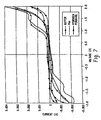
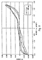
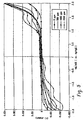
- FIGURES 8 and 9 show exemplary voltammograms for glassy carbon and pyrolytic graphite, respectively.
- the current remains relatively stable. This plateau region overlaps the voltage range in which the electrode shows greater sensitivity to peracetic acid than to hydrogen peroxide.
Landscapes
- Chemical & Material Sciences (AREA)
- Life Sciences & Earth Sciences (AREA)
- Health & Medical Sciences (AREA)
- Biochemistry (AREA)
- General Physics & Mathematics (AREA)
- Electrochemistry (AREA)
- Physics & Mathematics (AREA)
- Analytical Chemistry (AREA)
- Molecular Biology (AREA)
- General Health & Medical Sciences (AREA)
- Chemical Kinetics & Catalysis (AREA)
- Immunology (AREA)
- Pathology (AREA)
- Apparatus For Disinfection Or Sterilisation (AREA)
- Investigating Or Analyzing Materials By The Use Of Electric Means (AREA)
- Investigating Or Analysing Materials By The Use Of Chemical Reactions (AREA)
- Investigating Or Analyzing Non-Biological Materials By The Use Of Chemical Means (AREA)
Claims (16)
- Eine Methode zur Messung der Konzentration von Peressigsäure in einer, unter anderem, Wasserstoffperoxid enthaltenden Lösung, und die Methode daraus besteht, dassin die zu messende Lösung eingebracht werden, dass eine Mess-Spannung an der Arbeitselektrode angelegt und entweder der zwischen der Arbeitselektrode und der Referenzelektrode oder zwischen der Arbeitselektrode und, sofern vorhanden, der Zählelektrode (122) fließende Strom gemessen wird und dass ein Konvertierung des gemessenen Stroms in eine Anzeige für die Peressigsäure-Konzentration der Lösung erfolgt, wobei die Methode dadurch gekennzeichnet ist, dass:(a) eine Kohlenstoff-Arbeitselektrode (118) und eine Referenzelektrode (120) oder(b) eine Kohlenstoff-Arbeitselektrode (118), eine Referenzelektrode (120) und eine Zählelektrode (122)die an die Arbeitselektrode angelegte Mess-Spannung gezielt pulsiert wird;die Mess-Spannung so gewählt wird, dass der daraufhin fließende Strom abhängig ist von einer Konzentration der Peressigsäure und im Wesentlichen unabhängig von der Konzentration des Wasserstoffperoxids in der Lösung, wobei die Mess-Spannung in einem Bereich von -0,5 bis -1,4 Volt relativ zu einer Silber/Silberchlorid-Referenzelektrode liegt.
- Die Methode gemäß Anspruch 1, des weiteren dadurch gekennzeichnet, dass
die Mess-Spannung so gewählt wird, das der Anteil des auf Grund der Peressigsäure fließenden Stroms wenigstens zehnmal so hoch ist wie der bei einer vergleichbaren Konzentration des Wasserstoffperoxids. - Die Methode gemäß eines beliebigen der vorhergehenden Ansprüche 1 und 2 und des weiteren dadurch gekennzeichnet, dass
die Mess-Spannung in dem Bereich liegt, wo nur eine geringe Diffusion an der Elektrode stattfindet.. - Die Methode gemäß eines beliebigen der vorhergehenden Ansprüche 1 bis 3 und des weiteren dadurch gekennzeichnet, dass
die Mess-Spannung so gewählt wird, dass ein hoher Rauschabstand erzielt wird. - Die Methode gemäß eines beliebigen der vorhergehenden Ansprüche 1 bis 4 und des weiteren dadurch gekennzeichnet, dass
die Mess-Spannung so gewählt wird, dass sie im Bereich eines Strom/Spannungsplateaus liegt, wo also der Strom relativ unempfindlich ist gegenüber kleineren Schwankungen der Mess-Spannung. - Die Methode gemäß eines beliebigen der vorhergehenden Ansprüche 1 bis 5 und des weiteren dadurch gekennzeichnet, dass
die Arbeitselektrode aus pyrolytischem Graphit besteht und die Mess-Spannung in dem Bereich zwischen -1,1 und -1,3 Volt relativ zu einer Silber/Silberchlorid-Referenzelektrode liegt. - Die Methode gemäß eines beliebigen der vorhergehenden Ansprüche 1 bis 6 und des weiteren dadurch gekennzeichnet, dass
die Konzentration der Peressigsäure in dem Bereich zwischen 100 und 3000 ppm liegt. - Die Methode gemäß Anspruch 7, des weiteren dadurch gekennzeichnet, dass
die Konzentration der Peressigsäure in weniger als einer Minute bestimmt werden kann. - Die Methode gemäß eines beliebigen der vorhergehenden Ansprüche 1 bis 8 und des weiteren dadurch gekennzeichnet, dass
das gezielte Anlegen der Mess-Spannung und die Messung des Stroms in Intervallen von ungefähr zehn bis dreißig Sekunden wiederholt wird. - Die Methode gemäß eines beliebigen der vorhergehenden Ansprüche 1 bis 9 und des weiteren dadurch gekennzeichnet, dass
vor dem Anlegen der Mess-Spannung,
die Arbeitselektrode konditioniert wird und zwar durch Anlegen zumindest eines positiven Spannungspulses und durch Anlegen zumindest eines negativen Spannungspulses an die Elektrode. - Die Methode gemäß eines beliebigen der vorhergehenden Ansprüche 1 bis 10 und des weiteren dadurch gekennzeichnet, dass
die Temperatur der Lösung in direkter Nähe der Elektroden gemessen wird; und
Der Messwert des Stroms hinsichtlich der Differenz zwischen gemessener Temperatur und einer vorher spezifizierten Temperatur korrigiert wird. - Die Methode gemäß eines beliebigen der vorhergehenden Ansprüche 1 bis 11 und des weiteren dadurch gekennzeichnet, dass
die Konzentration der Peressigsäure in der Lösung erhöht wird, sobald die Konzentration unter einen vorher spezifizierten Wert fällt. - Die Methode gemäß eines beliebigen der vorhergehenden Ansprüche 1 bis 12, des weiteren dadurch gekennzeichnet, dass
vor dem Schritt des Eintauchens einer Arbeitselektrode und einer Referenzelektrode in die zu prüfende Lösung,
die Lösung durch einen Behandlungsbehälter (12), in dem sich die zu dekontaminierenden Gegenstände befinden, zirkuliert wird; und
der Schritt des Eintauchens der Arbeitselektrode, der Referenzelektrode und, sofern vorhanden, der Zählelektrode in die zu prüfende Lösung auch umfasst,
dass der zirkulierenden Lösung eine Probe entnommen und diese in eine Kammer (114) umgefüllt wird und damit die Benetzung der Elektroden erfolgt. - Die Methode gemäß Anspruch 13, des weiteren dadurch gekennzeichnet, dass
vor dem Schritt des Zirkulierens der Lösung durch den Behandlungsbehälter
eine Vorkonditionierungs-Lösung einschließlich Puffer und Netzmittel durch den Behandlungsbehälter gepumpt wird; und
der Vorkonditionierungs-Lösung eine Probe entnommen und in die Kammer gefüllt wird; und
eine pulsierende Spannung zwischen Referenz- und Arbeitselektrode angelegt wird, um somit Rückstände von der Arbeitselektrode zu entfernen. - Die Methode gemäß eines beliebigen der vorhergehenden Ansprüche 13 und 14 und des weiteren dadurch gekennzeichnet, dass
vor dem Schritt der Entnahme einer Probe aus der zirkulierenden Lösung und Umfüllen dieser Probe in eine Kammer
die Kammer mit Lösung gefüllt wird; und
die Lösung aus der Kammer entleert wird, um somit Rückstände von vorherigen Messungen aus der Kammer zu entfernen. - Die Methode gemäß eines beliebigen der vorhergehenden Ansprüche 13 bis 15 und des weiteren dadurch gekennzeichnet, dass
der Messwert des Stroms an ein Regelsystem (80) übertragen wird, das zumindest eines der folgenden Schritte ausführt, wenn der gemessene Strom unter einem vorher spezifizierten Mindestwert liegt:Abrechen des Dekontaminationsvorgangs;Verlängern des Dekontaminationsvorgangs als Kompensation für die geringere Konzentration der Peressigsäure;Steuerung der Zufuhr von zusätzlicher Peressigsäure in die zirkulierende Lösung; undAusgabe eines Signals, mit dem angezeigt wird, dass die Konzentration der Peressigsäure unter einem vorher spezifizierten Mindestwert liegt.
Applications Claiming Priority (3)
| Application Number | Priority Date | Filing Date | Title |
|---|---|---|---|
| US09/499,421 US6558529B1 (en) | 2000-02-07 | 2000-02-07 | Electrochemical sensor for the specific detection of peroxyacetic acid in aqueous solutions using pulse amperometric methods |
| US499421 | 2000-02-07 | ||
| PCT/US2001/003885 WO2001057513A2 (en) | 2000-02-07 | 2001-02-07 | Electrochemical sensor for the specific detection of peracetic acid in aqueous solutions using pulse amperometric methods |
Publications (2)
| Publication Number | Publication Date |
|---|---|
| EP1254366A2 EP1254366A2 (de) | 2002-11-06 |
| EP1254366B1 true EP1254366B1 (de) | 2005-05-11 |
Family
ID=23985200
Family Applications (1)
| Application Number | Title | Priority Date | Filing Date |
|---|---|---|---|
| EP01907053A Expired - Lifetime EP1254366B1 (de) | 2000-02-07 | 2001-02-07 | Elektrochemischer sensor zur bestimmung von peressigsäure in wässerigen lösungen mittels pulsamperometrischen-verfahren |
Country Status (9)
| Country | Link |
|---|---|
| US (2) | US6558529B1 (de) |
| EP (1) | EP1254366B1 (de) |
| JP (1) | JP2003521710A (de) |
| AT (1) | ATE295536T1 (de) |
| AU (2) | AU2001234879B2 (de) |
| CA (1) | CA2399692C (de) |
| DE (1) | DE60110752T2 (de) |
| ES (1) | ES2242730T3 (de) |
| WO (1) | WO2001057513A2 (de) |
Cited By (1)
| Publication number | Priority date | Publication date | Assignee | Title |
|---|---|---|---|---|
| US7641784B2 (en) | 2003-01-30 | 2010-01-05 | Tanita Corporation | Method for measuring by means of chemical sensor, and chemical sensor type measuring apparatus |
Families Citing this family (39)
| Publication number | Priority date | Publication date | Assignee | Title |
|---|---|---|---|---|
| GB0208095D0 (en) * | 2002-04-09 | 2002-05-22 | Dobson John V | Electrochemical sensor system and sensing method |
| AT411400B (de) * | 2002-05-31 | 2003-12-29 | Hoffmann La Roche | Verfahren und vorrichtung zur messung von blutgasparametern |
| US20040262170A1 (en) * | 2003-06-27 | 2004-12-30 | Steris Inc. | Sensor for sensing a chemical component concentration using an electroactive material |
| EP1713926B1 (de) | 2004-02-06 | 2012-08-01 | Bayer HealthCare, LLC | Oxidierbare verbindungen als interne referenz in biosensoren und deren verwendung |
| GB2417323A (en) * | 2004-08-17 | 2006-02-22 | Oxford Biosensors Ltd | A method of operating an electrochemical sensor by applying a time variable potential between the electrodes. |
| DE102004047096A1 (de) * | 2004-09-29 | 2006-04-06 | Henkel Kgaa | Amperometrisches Verfahren zur Bestimmung und Steuerung der Biozidkonzentration in einem wasserführenden System |
| ES2717135T3 (es) | 2005-07-20 | 2019-06-19 | Ascensia Diabetes Care Holdings Ag | Método para señalar al usuario para que añada una muestra adicional a una tira de prueba, método para medir la temperatura de una muestra y métodos para determinar la concentración de un analito basados en amperometría controlada |
| EP3483598A1 (de) | 2005-09-30 | 2019-05-15 | Ascensia Diabetes Care Holdings AG | Gesteuerte voltammetrie |
| CN100433373C (zh) * | 2005-12-28 | 2008-11-12 | 大连海事大学 | 一种纳米TiO2-M薄膜紫外光传感器及其制备方法 |
| US7468124B2 (en) * | 2006-05-11 | 2008-12-23 | International Business Machines Corporation | Method and apparatus for copper corrosion prevention during wet clean |
| MX2009004400A (es) | 2006-10-24 | 2009-05-11 | Bayer Healthcare Llc | Amperimetria de decadencia transitoria. |
| US8071390B2 (en) * | 2007-06-05 | 2011-12-06 | Ecolab Usa Inc. | Temperature stabilized optical cell and method |
| US8076154B2 (en) * | 2007-06-05 | 2011-12-13 | Ecolab Usa Inc. | Method of calibration for nonlinear optical sensor |
| US8119412B2 (en) * | 2007-06-05 | 2012-02-21 | Ecolab Usa Inc. | Kinetic determination of peracid and/or peroxide concentrations |
| WO2009076302A1 (en) | 2007-12-10 | 2009-06-18 | Bayer Healthcare Llc | Control markers for auto-detection of control solution and methods of use |
| EP2235515B1 (de) * | 2008-01-23 | 2016-10-19 | Evoqua Water Technologies LLC | Amperometrische sonde mit niedrigem stromverbrauch |
| EP2349442B1 (de) | 2008-10-15 | 2023-07-26 | University of Tennessee Research Foundation | Verfahren und vorrichtung zum nachweis der bioverfügbaren arzneimittelkonzentration in einer flüssigkeitsprobe |
| US11375929B2 (en) | 2008-10-15 | 2022-07-05 | The University Of Tennessee Research Foundation | Method and device for detection of bioavailable drug concentration in a fluid sample |
| EP2398376A1 (de) * | 2009-02-17 | 2011-12-28 | Siemens Aktiengesellschaft | Gastroskop |
| JP2010243452A (ja) * | 2009-04-10 | 2010-10-28 | Apurikusu:Kk | 過酢酸濃度連続測定方法及び過酢酸濃度連続測定装置 |
| EP2459996A4 (de) * | 2009-07-27 | 2016-10-19 | Diversey Inc | Systeme und verfahren zur erkennung eines h202-spiegels in einem aseptischen kaltfüllungssystem mit einer peressigsäure-reinigungslösung |
| WO2011027288A2 (en) * | 2009-09-03 | 2011-03-10 | Ecolab Usa Inc. | Electrolytic degradation systems and methods usable in industrial applications |
| DE102011003187A1 (de) * | 2011-01-26 | 2012-07-26 | Evonik Degussa Gmbh | Vorrichtung und Verfahren zur Verringerung des Gehalts an Wasserstoffperoxid und Peressigsäure in einem Wasserstrom |
| KR20140100930A (ko) * | 2011-06-03 | 2014-08-18 | 디엑스업클로스 | 미생물 동정 및 미생물 카운팅 및 항미생물제 민감성 측정을 위한 장치 및 방법 |
| US10837949B1 (en) * | 2012-03-22 | 2020-11-17 | Piers Richard Warburton | Peracetic acid sensor with filter to remove hydrogen peroxide |
| EP2856133B1 (de) | 2012-06-01 | 2018-05-09 | The University of Tennessee Research Foundation | Verbessertes verfahren und vorrichtung zum nachweis bioverfügbarer wirkstoffkonzentrationen |
| US9459233B2 (en) | 2012-06-25 | 2016-10-04 | Steris Corporation | Amperometric gas sensor |
| EP2980576A1 (de) * | 2014-07-31 | 2016-02-03 | Electrochemical Sensor Technological (EST) Limited | Elektrochemisches Sensorsystem und Erfassungsverfahren |
| EP3284393B1 (de) * | 2015-05-21 | 2019-12-04 | Olympus Corporation | Endoskopreprozessor |
| CN105238687A (zh) * | 2015-09-17 | 2016-01-13 | 北京托摩根生物科技有限公司 | 一种新型微生物连续供氧bod测定系统 |
| US10889848B2 (en) | 2017-07-14 | 2021-01-12 | American Sterilizer Company | Process for determining viability of test microorganisms of biological indicator and sterilization detection device for determining same |
| US10876144B2 (en) | 2017-07-14 | 2020-12-29 | American Sterilizer Company | Process for determining viability of test microorganisms of biological indicator and sterilization detection device for determining same |
| US10900062B2 (en) | 2017-07-14 | 2021-01-26 | American Sterilizer Company | Process for determining viability of test microorganisms of biological indicator and sterilization detection device for determining same |
| JP6817594B2 (ja) | 2017-12-01 | 2021-01-20 | パナソニックIpマネジメント株式会社 | 液体処理装置 |
| GB2582582B (en) * | 2019-03-26 | 2021-03-31 | Kalium Health Ltd | Conditioning an ion-selective electrode |
| US11927577B2 (en) | 2019-05-09 | 2024-03-12 | Cs Medical, Llc | Chemical indicator solution, apparatus, and method for determining concentration of a chemical within a fluid sample |
| JP7385682B2 (ja) * | 2019-05-31 | 2023-11-22 | エコラボ ユーエスエー インコーポレイティド | 導電率測定による過酸濃度の監視方法および過酸組成物 |
| US20230051427A1 (en) * | 2020-01-17 | 2023-02-16 | Garwood Medical Devices, Llc | Galvanostatic method of microbe removal from metal orthopedic devices |
| WO2024111582A1 (ja) * | 2022-11-22 | 2024-05-30 | オリンパス株式会社 | 過酢酸測定装置校正方法及び過酢酸計校正システム |
Family Cites Families (32)
| Publication number | Priority date | Publication date | Assignee | Title |
|---|---|---|---|---|
| US2846386A (en) * | 1953-06-22 | 1958-08-05 | Canadian Aviat Electronics Ltd | Reference electrode for making ph measurements |
| US3196100A (en) * | 1961-09-07 | 1965-07-20 | Cambridge Instr Company Inc | Oxygen detecting and measuring apparatus |
| US3644824A (en) | 1970-02-09 | 1972-02-22 | Atomic Energy Authority Uk | Polarograph apparatus |
| US4216069A (en) | 1979-01-31 | 1980-08-05 | Shell Oil Company | Detector for trace lead in gasolines |
| DE3129988A1 (de) * | 1981-07-29 | 1983-02-17 | Siemens AG, 1000 Berlin und 8000 München | "verfahren und vorrichtung zur bestimmung von harnstoff" |
| US4571292A (en) | 1982-08-12 | 1986-02-18 | Case Western Reserve University | Apparatus for electrochemical measurements |
| US4566949A (en) * | 1983-10-19 | 1986-01-28 | Hewlett-Packard Company | Method of operating a self cleaning electrochemical detector |
| USD292229S (en) | 1984-06-21 | 1987-10-06 | Arden Medical Systems, Inc. | Disposable sensor card with receptacle and electrode sensors for chemical analysis of biological fluids |
| US4897162A (en) | 1986-11-14 | 1990-01-30 | The Cleveland Clinic Foundation | Pulse voltammetry |
| GB8628441D0 (en) | 1986-11-27 | 1986-12-31 | Unilever Plc | Disinfectant dilution |
| GB8711736D0 (en) | 1987-05-19 | 1987-06-24 | Genetics Int Inc | Electroenzymic catalysis |
| GB8806145D0 (en) | 1988-03-15 | 1988-04-13 | Unilever Plc | Electrical sensor & method |
| DE3829512A1 (de) | 1988-08-31 | 1990-03-08 | Prominent Dosiertechnik Gmbh | Anordnung zum ueberwachen der ausgangsstroemung einer dosierpumpe |
| US5131999A (en) | 1990-01-16 | 1992-07-21 | The National University Of Singapore | Voltammetric detector for flow analysis |
| DE4027028C2 (de) | 1990-08-27 | 1994-09-15 | Prominent Dosiertechnik Gmbh | Verfahren und Vorrichtung zur Bestimmung der Durchflußmenge eines Fluids mit einer pulsierenden Strömung |
| JP2619319B2 (ja) * | 1991-06-18 | 1997-06-11 | ミンテック コーポレーション | 過酢酸−過酸化水素溶液のためのセンサー |
| EP0589873B1 (de) | 1991-06-18 | 1999-08-25 | Minntech Corporation | Vorrichtung zur automatischen Verdünnung von Peressigsäure und Wasserstoffperoxid |
| US5310524A (en) | 1992-02-11 | 1994-05-10 | Minntech Corporation | Catheter reprocessing and sterilizing system |
| DE4223228C2 (de) | 1992-07-15 | 1995-01-19 | Prominent Dosiertechnik Gmbh | Verfahren zur Bestimmung von Persäuren |
| US5364510A (en) | 1993-02-12 | 1994-11-15 | Sematech, Inc. | Scheme for bath chemistry measurement and control for improved semiconductor wet processing |
| US5374892A (en) | 1993-03-04 | 1994-12-20 | Georgia Tech Research Corporation | Digital electrochemical instrument with background compensation |
| US5366609A (en) | 1993-06-08 | 1994-11-22 | Boehringer Mannheim Corporation | Biosensing meter with pluggable memory key |
| JP3318065B2 (ja) | 1993-08-09 | 2002-08-26 | オリンパス光学工業株式会社 | 内視鏡洗浄装置 |
| DE4342787C1 (de) | 1993-12-15 | 1995-07-06 | Thiedig & Co Dr | Verfahren zur quantitativen Bestimmung elektrochemisch reduzierbarer oder oxidierbarer Stoffe, insbesondere von Peroxiessigsäure im Gemisch mit anderen oxidierenden Stoffen |
| US5470484A (en) | 1994-01-13 | 1995-11-28 | Buckman Laboratories International, Inc. | Method and apparatus for controlling the feed of water treatment chemicals using a voltammetric sensor |
| DE4412576A1 (de) | 1994-04-13 | 1995-10-19 | Henkel Kgaa | Sensorsystem zur Desinfektionsmittelerfassung und Dosierung in Textilwaschanlagen (Senking-Anlagen) |
| US5644501A (en) | 1994-12-06 | 1997-07-01 | Lin; Shengfu | Method of using a computer to collect chemical signals directly |
| US5873990A (en) | 1995-08-22 | 1999-02-23 | Andcare, Inc. | Handheld electromonitor device |
| US5882590A (en) * | 1996-07-03 | 1999-03-16 | American Sterilizer Company | Monitoring and control of sterilization processes with semiconductor sensor modules |
| JPH1096710A (ja) | 1996-09-25 | 1998-04-14 | Kdk Corp | イオン濃度測定方法 |
| US6203767B1 (en) | 1998-11-06 | 2001-03-20 | Steris Corporation | Peracetic acid card reader and card style sensor |
| JP3234585B2 (ja) * | 1999-06-30 | 2001-12-04 | 理工協産株式会社 | 過酢酸及び過酸化水素の分別測定法 |
-
2000
- 2000-02-07 US US09/499,421 patent/US6558529B1/en not_active Expired - Lifetime
-
2001
- 2001-02-07 EP EP01907053A patent/EP1254366B1/de not_active Expired - Lifetime
- 2001-02-07 JP JP2001556311A patent/JP2003521710A/ja active Pending
- 2001-02-07 ES ES01907053T patent/ES2242730T3/es not_active Expired - Lifetime
- 2001-02-07 AU AU2001234879A patent/AU2001234879B2/en not_active Ceased
- 2001-02-07 AU AU3487901A patent/AU3487901A/xx active Pending
- 2001-02-07 WO PCT/US2001/003885 patent/WO2001057513A2/en active IP Right Grant
- 2001-02-07 AT AT01907053T patent/ATE295536T1/de not_active IP Right Cessation
- 2001-02-07 CA CA002399692A patent/CA2399692C/en not_active Expired - Fee Related
- 2001-02-07 DE DE60110752T patent/DE60110752T2/de not_active Expired - Fee Related
-
2003
- 2003-04-01 US US10/404,609 patent/US20030209450A1/en not_active Abandoned
Cited By (2)
| Publication number | Priority date | Publication date | Assignee | Title |
|---|---|---|---|---|
| US7641784B2 (en) | 2003-01-30 | 2010-01-05 | Tanita Corporation | Method for measuring by means of chemical sensor, and chemical sensor type measuring apparatus |
| DE102004004392B4 (de) * | 2003-01-30 | 2011-08-18 | Tanita Corp. | Messmethode mit Hilfe eines chemischen Sensors und eines chemischen Sensormessgerätes |
Also Published As
| Publication number | Publication date |
|---|---|
| EP1254366A2 (de) | 2002-11-06 |
| JP2003521710A (ja) | 2003-07-15 |
| ES2242730T3 (es) | 2005-11-16 |
| US20030209450A1 (en) | 2003-11-13 |
| DE60110752T2 (de) | 2006-01-26 |
| WO2001057513A2 (en) | 2001-08-09 |
| US6558529B1 (en) | 2003-05-06 |
| DE60110752D1 (de) | 2005-06-16 |
| ATE295536T1 (de) | 2005-05-15 |
| CA2399692A1 (en) | 2001-08-09 |
| WO2001057513A3 (en) | 2002-02-07 |
| AU2001234879B2 (en) | 2005-03-24 |
| AU3487901A (en) | 2001-08-14 |
| CA2399692C (en) | 2009-01-20 |
Similar Documents
| Publication | Publication Date | Title |
|---|---|---|
| EP1254366B1 (de) | Elektrochemischer sensor zur bestimmung von peressigsäure in wässerigen lösungen mittels pulsamperometrischen-verfahren | |
| AU2001234879A1 (en) | Electrochemical sensor for the specific detection of peracetic acid in aqueous solutions using pulse amperometric methods | |
| US6494964B1 (en) | Monitoring of cleaning process | |
| EP1707222B1 (de) | Überwachung eines Reinigungsverfahrens | |
| EP1051200B1 (de) | Elektrolytische synthese von peressigsäure | |
| EP1709979B1 (de) | Reinigungsindikator zur Überwachung eines Reinigungsvorgangs | |
| CA2481148C (en) | Cartridge holder for automated reprocessor | |
| WO1999008719B1 (en) | Sterilization apparatus utilizing catholyte and anolyte solutions | |
| AU2009203008A1 (en) | Method and apparatus for producing negative and positive oxidative reductive potential (ORP) water | |
| US7246627B2 (en) | Monitoring of cleaning process | |
| US6203767B1 (en) | Peracetic acid card reader and card style sensor | |
| JP7489991B2 (ja) | 過酢酸濃度計 | |
| EP1254486B1 (de) | Dauerhafte kohlenstoffelektrode | |
| JPH08211072A (ja) | 分析装置 | |
| JPH0989827A (ja) | 電気センサー | |
| JP3687789B2 (ja) | 物質濃度計測装置 | |
| WO2024111582A1 (ja) | 過酢酸測定装置校正方法及び過酢酸計校正システム | |
| JP4319795B2 (ja) | 電位検出装置 | |
| KR19990006864A (ko) | 클리닝 과정의 감시 방법 |
Legal Events
| Date | Code | Title | Description |
|---|---|---|---|
| PUAI | Public reference made under article 153(3) epc to a published international application that has entered the european phase |
Free format text: ORIGINAL CODE: 0009012 |
|
| 17P | Request for examination filed |
Effective date: 20020821 |
|
| AK | Designated contracting states |
Kind code of ref document: A2 Designated state(s): AT BE CH CY DE DK ES FI FR GB GR IE IT LI LU MC NL PT SE TR |
|
| AX | Request for extension of the european patent |
Free format text: AL;LT;LV;MK;RO;SI |
|
| RIN1 | Information on inventor provided before grant (corrected) |
Inventor name: DESANTIS, BRIAN, J. Inventor name: SCHINDLY, BRIAN, E. Inventor name: THOMAS, KAREN, L. Inventor name: LEWANDOWSKI, JAN, J. Inventor name: MCVEY, IAIN, F. |
|
| 17Q | First examination report despatched |
Effective date: 20040604 |
|
| GRAP | Despatch of communication of intention to grant a patent |
Free format text: ORIGINAL CODE: EPIDOSNIGR1 |
|
| GRAS | Grant fee paid |
Free format text: ORIGINAL CODE: EPIDOSNIGR3 |
|
| GRAA | (expected) grant |
Free format text: ORIGINAL CODE: 0009210 |
|
| AK | Designated contracting states |
Kind code of ref document: B1 Designated state(s): AT BE CH CY DE DK ES FI FR GB GR IE IT LI LU MC NL PT SE TR |
|
| PG25 | Lapsed in a contracting state [announced via postgrant information from national office to epo] |
Ref country code: AT Free format text: LAPSE BECAUSE OF FAILURE TO SUBMIT A TRANSLATION OF THE DESCRIPTION OR TO PAY THE FEE WITHIN THE PRESCRIBED TIME-LIMIT Effective date: 20050511 |
|
| REG | Reference to a national code |
Ref country code: GB Ref legal event code: FG4D |
|
| REG | Reference to a national code |
Ref country code: CH Ref legal event code: EP |
|
| REG | Reference to a national code |
Ref country code: IE Ref legal event code: FG4D |
|
| REF | Corresponds to: |
Ref document number: 60110752 Country of ref document: DE Date of ref document: 20050616 Kind code of ref document: P |
|
| PG25 | Lapsed in a contracting state [announced via postgrant information from national office to epo] |
Ref country code: GR Free format text: LAPSE BECAUSE OF FAILURE TO SUBMIT A TRANSLATION OF THE DESCRIPTION OR TO PAY THE FEE WITHIN THE PRESCRIBED TIME-LIMIT Effective date: 20050811 Ref country code: DK Free format text: LAPSE BECAUSE OF FAILURE TO SUBMIT A TRANSLATION OF THE DESCRIPTION OR TO PAY THE FEE WITHIN THE PRESCRIBED TIME-LIMIT Effective date: 20050811 |
|
| REG | Reference to a national code |
Ref country code: SE Ref legal event code: TRGR |
|
| REG | Reference to a national code |
Ref country code: CH Ref legal event code: NV Representative=s name: R. A. EGLI & CO. PATENTANWAELTE |
|
| PG25 | Lapsed in a contracting state [announced via postgrant information from national office to epo] |
Ref country code: PT Free format text: LAPSE BECAUSE OF FAILURE TO SUBMIT A TRANSLATION OF THE DESCRIPTION OR TO PAY THE FEE WITHIN THE PRESCRIBED TIME-LIMIT Effective date: 20051019 |
|
| REG | Reference to a national code |
Ref country code: ES Ref legal event code: FG2A Ref document number: 2242730 Country of ref document: ES Kind code of ref document: T3 |
|
| PG25 | Lapsed in a contracting state [announced via postgrant information from national office to epo] |
Ref country code: MC Free format text: LAPSE BECAUSE OF NON-PAYMENT OF DUE FEES Effective date: 20060228 |
|
| PLBE | No opposition filed within time limit |
Free format text: ORIGINAL CODE: 0009261 |
|
| STAA | Information on the status of an ep patent application or granted ep patent |
Free format text: STATUS: NO OPPOSITION FILED WITHIN TIME LIMIT |
|
| ET | Fr: translation filed | ||
| 26N | No opposition filed |
Effective date: 20060214 |
|
| BECA | Be: change of holder's address |
Owner name: AMERICAN STERILIZER CY5960 HEISLEY ROAD, US - MENT Effective date: 20050511 |
|
| BECH | Be: change of holder |
Owner name: AMERICAN STERILIZER CY Effective date: 20050511 |
|
| NLS | Nl: assignments of ep-patents |
Owner name: AMERICAN STERILIZER COMPANY Effective date: 20080130 |
|
| PGFP | Annual fee paid to national office [announced via postgrant information from national office to epo] |
Ref country code: CH Payment date: 20080228 Year of fee payment: 8 |
|
| PGFP | Annual fee paid to national office [announced via postgrant information from national office to epo] |
Ref country code: FI Payment date: 20080228 Year of fee payment: 8 Ref country code: LU Payment date: 20080307 Year of fee payment: 8 Ref country code: NL Payment date: 20080224 Year of fee payment: 8 Ref country code: SE Payment date: 20080227 Year of fee payment: 8 |
|
| PG25 | Lapsed in a contracting state [announced via postgrant information from national office to epo] |
Ref country code: TR Free format text: LAPSE BECAUSE OF FAILURE TO SUBMIT A TRANSLATION OF THE DESCRIPTION OR TO PAY THE FEE WITHIN THE PRESCRIBED TIME-LIMIT Effective date: 20050511 |
|
| PGFP | Annual fee paid to national office [announced via postgrant information from national office to epo] |
Ref country code: BE Payment date: 20080306 Year of fee payment: 8 |
|
| REG | Reference to a national code |
Ref country code: CH Ref legal event code: PUE Owner name: AMERICAN STERILIZER COMPANY Free format text: STERIS INC.#43425 BUSINESS PARK DRIVE#TEMECULA, CALIFORNIA 92590 (US) -TRANSFER TO- AMERICAN STERILIZER COMPANY#5960 HEISLEY ROAD#MENTOR, OH 44060 (US) |
|
| REG | Reference to a national code |
Ref country code: FR Ref legal event code: TP |
|
| PG25 | Lapsed in a contracting state [announced via postgrant information from national office to epo] |
Ref country code: CY Free format text: LAPSE BECAUSE OF FAILURE TO SUBMIT A TRANSLATION OF THE DESCRIPTION OR TO PAY THE FEE WITHIN THE PRESCRIBED TIME-LIMIT Effective date: 20050511 |
|
| PGFP | Annual fee paid to national office [announced via postgrant information from national office to epo] |
Ref country code: ES Payment date: 20090226 Year of fee payment: 9 Ref country code: IE Payment date: 20090305 Year of fee payment: 9 |
|
| PGFP | Annual fee paid to national office [announced via postgrant information from national office to epo] |
Ref country code: GB Payment date: 20090227 Year of fee payment: 9 |
|
| BERE | Be: lapsed |
Owner name: AMERICAN STERILIZER CY Effective date: 20090228 |
|
| PGFP | Annual fee paid to national office [announced via postgrant information from national office to epo] |
Ref country code: DE Payment date: 20090331 Year of fee payment: 9 Ref country code: IT Payment date: 20090224 Year of fee payment: 9 |
|
| REG | Reference to a national code |
Ref country code: CH Ref legal event code: PL |
|
| EUG | Se: european patent has lapsed | ||
| PG25 | Lapsed in a contracting state [announced via postgrant information from national office to epo] |
Ref country code: FI Free format text: LAPSE BECAUSE OF NON-PAYMENT OF DUE FEES Effective date: 20090207 Ref country code: CH Free format text: LAPSE BECAUSE OF NON-PAYMENT OF DUE FEES Effective date: 20090228 Ref country code: LI Free format text: LAPSE BECAUSE OF NON-PAYMENT OF DUE FEES Effective date: 20090228 |
|
| PGFP | Annual fee paid to national office [announced via postgrant information from national office to epo] |
Ref country code: FR Payment date: 20090217 Year of fee payment: 9 |
|
| NLV4 | Nl: lapsed or anulled due to non-payment of the annual fee |
Effective date: 20090901 |
|
| PG25 | Lapsed in a contracting state [announced via postgrant information from national office to epo] |
Ref country code: NL Free format text: LAPSE BECAUSE OF NON-PAYMENT OF DUE FEES Effective date: 20090901 |
|
| PG25 | Lapsed in a contracting state [announced via postgrant information from national office to epo] |
Ref country code: BE Free format text: LAPSE BECAUSE OF NON-PAYMENT OF DUE FEES Effective date: 20090228 |
|
| GBPC | Gb: european patent ceased through non-payment of renewal fee |
Effective date: 20100207 |
|
| REG | Reference to a national code |
Ref country code: FR Ref legal event code: ST Effective date: 20101029 |
|
| REG | Reference to a national code |
Ref country code: IE Ref legal event code: MM4A |
|
| PG25 | Lapsed in a contracting state [announced via postgrant information from national office to epo] |
Ref country code: IE Free format text: LAPSE BECAUSE OF NON-PAYMENT OF DUE FEES Effective date: 20100208 Ref country code: FR Free format text: LAPSE BECAUSE OF NON-PAYMENT OF DUE FEES Effective date: 20100301 |
|
| PG25 | Lapsed in a contracting state [announced via postgrant information from national office to epo] |
Ref country code: DE Free format text: LAPSE BECAUSE OF NON-PAYMENT OF DUE FEES Effective date: 20100901 |
|
| PG25 | Lapsed in a contracting state [announced via postgrant information from national office to epo] |
Ref country code: GB Free format text: LAPSE BECAUSE OF NON-PAYMENT OF DUE FEES Effective date: 20100207 Ref country code: IT Free format text: LAPSE BECAUSE OF NON-PAYMENT OF DUE FEES Effective date: 20100207 |
|
| PG25 | Lapsed in a contracting state [announced via postgrant information from national office to epo] |
Ref country code: LU Free format text: LAPSE BECAUSE OF NON-PAYMENT OF DUE FEES Effective date: 20090207 |
|
| PG25 | Lapsed in a contracting state [announced via postgrant information from national office to epo] |
Ref country code: SE Free format text: LAPSE BECAUSE OF NON-PAYMENT OF DUE FEES Effective date: 20090208 |
|
| REG | Reference to a national code |
Ref country code: ES Ref legal event code: FD2A Effective date: 20111121 |
|
| PG25 | Lapsed in a contracting state [announced via postgrant information from national office to epo] |
Ref country code: ES Free format text: LAPSE BECAUSE OF NON-PAYMENT OF DUE FEES Effective date: 20100208 |