EP1252979A1 - Haltevorrichtung zum Halten von Kabeln an einem Roboterteil mit Rastelementen - Google Patents
Haltevorrichtung zum Halten von Kabeln an einem Roboterteil mit Rastelementen Download PDFInfo
- Publication number
- EP1252979A1 EP1252979A1 EP02008986A EP02008986A EP1252979A1 EP 1252979 A1 EP1252979 A1 EP 1252979A1 EP 02008986 A EP02008986 A EP 02008986A EP 02008986 A EP02008986 A EP 02008986A EP 1252979 A1 EP1252979 A1 EP 1252979A1
- Authority
- EP
- European Patent Office
- Prior art keywords
- arm
- robot
- fastening part
- locking elements
- fastening
- Prior art date
- Legal status (The legal status is an assumption and is not a legal conclusion. Google has not performed a legal analysis and makes no representation as to the accuracy of the status listed.)
- Granted
Links
- 210000001331 nose Anatomy 0.000 abstract description 5
- 238000013459 approach Methods 0.000 description 2
- 238000011161 development Methods 0.000 description 2
- 230000018109 developmental process Effects 0.000 description 2
- 238000005259 measurement Methods 0.000 description 2
Images


Classifications
-
- B—PERFORMING OPERATIONS; TRANSPORTING
- B25—HAND TOOLS; PORTABLE POWER-DRIVEN TOOLS; MANIPULATORS
- B25J—MANIPULATORS; CHAMBERS PROVIDED WITH MANIPULATION DEVICES
- B25J19/00—Accessories fitted to manipulators, e.g. for monitoring, for viewing; Safety devices combined with or specially adapted for use in connection with manipulators
- B25J19/0025—Means for supplying energy to the end effector
Definitions
- the invention relates to a holding device, in particular for holding additional parts such as cables, hoses or Like. on a robot part.
- U1 is a generic holding device known in which a multi-part ring part around a Robot part, like the flange of a robotic hand and against this is braced. If for any reason one Detachment of the holding device from the robot part required is, it is difficult to get the previous alignment back to achieve exactly; at least this must be measured precisely beforehand and then the alignment when you create it again be checked accordingly.
- this ring part radially extending arm of the holding device is formed with a circular cross section and on this a fastening part or block on which an additional part attached, can be frictionally fixed by tensioning is again true that when a loosening the exact angular alignment of the fastener and the linear Alignment along the axis of the arm is not easy and is easily reproducible, but for this purpose Before loosening and when reattaching measurements and adjustments are to be made.
- the invention is based on the object To further develop the holding device of the generic type, that a once desired definition and Alignment easily and without complex measurements in is reproducible faster.
- the invention provides a holding device for this before, which has locking elements.
- the locking elements can between individual parts movable relative to each other the holding device for reproducible relative determination the same to each other but also in this way on the holding device be provided that these as such on the robot part, like the flange of a robot hand, reproducible is definable.
- the invention is Accordingly, the device initially provided that a first locking elements around the robot part for interacting with locking elements on the robot part, the first locking elements as axially parallel grooves are formed with one or more ribs or cooperate lugs on the robot part for locking.
- the Robot part itself can have one or more ribs or noses be trained.
- the first locking elements on the inner circumference of the ring part are formed, in which case the Ribs or noses provided on the robot part on its outer circumference are.
- a reversal is basically also possible if a ring part of the holding device on the robot part an overlapping element, for example a bracket is provided which is firm, in particular insoluble is provided on the robot part and which engages over the ring part; in this case the bracket can be connected to an outer Partially engage the web in the external grooves.
- a bracket is provided which is firm, in particular insoluble is provided on the robot part and which engages over the ring part; in this case the bracket can be connected to an outer Partially engage the web in the external grooves.
- a robot part encompassing ring part consists of two parts that against the ring part can be clamped, in particular on an arm part along the longitudinal direction of the second locking elements are formed with on the inside of a fastening part trained locking elements for the additional part interact.
- the second locking elements along the arm the same one behind the other, transversely to the direction of extension of the arm extending ribs formed are with one or more grooves on the inner circumference of the Interact with the fastener.
- third locking elements by forming the cross-section of the outer contour of the arm and the inner contour of the fastening part with finite count is formed, the count of Inner contour of the fastening part equal to the number of Outer contour of the arm or a multiple thereof.
- Countiness denotes the angular possibility of twisting one Partly around an axis where a body is in itself is transferred, his positions are indistinguishable.
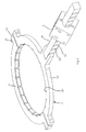
- the fastening device 1 has in the embodiment shown a ring part 2, an arm 3, a fastening element 4 for fastening additional parts, such as cables, hoses or the like in a robot part.
- the holding device 1 is by means of Ring part 2 around robot part 5, like a hand flange Robotic hand attached.
- the ring part 2 has two half rings 2.1, 2.2, which each have approaches 2.3, via the the half rings 2.1, 2.2 by means of screws 2.4 to the complete Ring part 2 are firmly connected.
- the half rings 2.1, 2.2 are on both sides of the robot part 5 created and then with the screws 2.4 together connected and thus firmly attached to the robot part 5.
- the arm 3 looks at an outer circumference, at least diagonally opposite longitudinal surfaces 3.1, 3.2 as second locking elements evenly spaced along the arm Ribs 3.3 for reproducible linear definition of the fastening part 4 along the direction of extension of arm 3 before.
- With the ribs 3.3 acts as a locking element one formed on the inner circumference of the fastening part 4 Groove 4.1 together.
- third locking elements on arm 3 and on the fastening part 4 for reproducible angular Fixing part 4 provided on arm 3. are generally formed such that the arm 3 is not designed as a cylinder rod or with a circular cross section but its outer contour as well as the inner contour of the fastening part 4 a finite count has, where the count of the inner contour of the fastening part 4 equal to or a multiple of the number of The outer contour of the arm 3 is.
- the arm 3 is cuboid, i.e. he has a square cross section with four edges and four corners and thus the number 4, while the inner contour the fastening part 4 the cross section of a Sterns with eight points, i.e. has a count of 8, the double in the illustrated embodiment is as large as the number of the circumferential contour of the Poor 3
- the serrations of the star inner contour of the fastening part 4 have a right in the illustrated embodiment Inside angle on the right outside angle of the edges of the Poor 3 corresponds. Basically, they should be numbered of the fixing part 4 determining star-shaped Notches or grooves have an inside angle that the Angle of the edges of the outer contour of the arm 3 corresponds. In the case of a triangular bar (number 3) with inside edge angles the inner contour of the fastening part should be 60 ° 4 a 6-, 9-, 12-pointed star (number 6.9 or 12) and should have the inside angle of the inside contour of the fastening part 4 also determining serrations Be 60 °.
Landscapes
- Engineering & Computer Science (AREA)
- Robotics (AREA)
- Mechanical Engineering (AREA)
- Manipulator (AREA)
- Clamps And Clips (AREA)
Abstract
Description
- Fig. 1
- eine Seitenansicht auf eine erfindungsgemäße Haltevorrichtung an einem geschnitten dargestellten Roboterteil, wie einem Handflansch;
- Fig. 2
- eine perspektivische Darstellung der erfindungsgemäßen Haltevorrichtung;
- Fig. 3
- ein Befestigungsteil entsprechend den Fig. 1 und 2 zur Befestigung eines Zusatzteils am Roboter in perspektivischer Darstellung mit Blick auf die Innenkontur.
- 1
- Befestigungsvorrichtung
- 2
- Ringteil
- 2.1, 2.2
- Halbringe
- 2.3
- Ansätze
- 2.4
- Schrauben
- 2.5
- achsparallele Nuten
- 3
- Arm
- 3.1, 3.2
- Längsflächen
- 3.3
- Rippen
- 4
- Befestigungselement
- 4.1
- Nut
- 5
- Roboterteil
- 5.1
- Nase
- 8
- Zähligkeit
Claims (12)
- Haltevorrichtung, insbesondere zum Halten von Zusatzteilen, wie Kabeln, Schläuchen oder dgl. an einem Roboterteil, gekennzeichnet durch Rastelemente.
- Haltevorrichtung nach Anspruch 1, dadurch gekennzeichnet, dass ein um das Roboterteil (5) umgreifendes Ringteil (2) erste Rastelemente (2.5) zum Zusammenwirken mit Rastelementen (5.1) am Roboterteil aufweist.
- Haltevorrichtung nach Anspruch 1 oder 2, dadurch gekennzeichnet, dass die ersten Rastelemente als achsparallele Nuten (2.5) ausgebildet sind, die mit einer oder mehreren Rippen oder Nasen (5.1) am Roboterteil zur Verrastung zusammenwirken.
- Vorrichtung nach einem der Ansprüche 1 bis 3, dadurch gekennzeichnet, dass die ersten Rastelemente (2.5) am Innenumfang des Ringteils (2) ausgebildet sind.
- Vorrichtung nach einem der vorangehenden Ansprüche, dadurch gekennzeichnet, dass ein ein Roboterteil (5) umgreifendes Ringteil (2) aus zwei Teilen (2.1, 2.2) besteht, die gegen das Ringteil (5) verspannbar sind.
- Vorrichtung nach einem der vorangehenden Ansprüche, dadurch gekennzeichnet, dass an einem Armteil (3) entlang dessen Längsrichtung zweite Rastelemente (2.3) ausgebildet sind, die mit an der Innenseite eines Befestigungsteils (4) für das Zusatzteil ausgebildeten Rastelementen zusammenwirken.
- Vorrichtung nach Anspruch 6, dadurch gekennzeichnet, dass die zweiten Rastelemente am Arm (3) durch sich entlang demselben hintereinander angeordnete, sich quer zur Erstreckungsrichtung des Armes (3) erstreckende Rippen (3.3) gebildet sind, die mit ein oder mehreren Nuten (4.1) am Innenumfang des Befestigungsteils (4) zusammenwirken.
- Vorrichtung nach einem der vorangehenden Ansprüche, gekennzeichnet durch über den Umfang des Stabes (3) und den Innenumfang des Befestigungsteils (4) gleichmäßig verteilte dritte Rastelemente.
- Vorrichtung nach Anspruch 8, dadurch gekennzeichnet, dass die dritten Rastelemente durch Ausbildung des Querschnitts der Außenkontur des Armes (3) und der Innenkontur des Befestigungsteils (4) mit endlicher Zähligkeit gebildet ist, wobei die Zähligkeit der Innenkontur des Befestigungsteils (4) gleich der Zähligkeit der Außenkontur des Armes (3) oder ein Vielfaches derselben ist.
- Vorrichtung nach Anspruch 9, dadurch gekennzeichnet, dass der Stab quadratisch (vier-zählig) ausgebildet ist.
- Vorrichtung nach Anspruch 10, dadurch gekennzeichnet, dass die Innenkontur des Befestigungsteils (4) sternförmig mit einer Acht-Zähligkeit (a') ausgebildet ist.
- Vorrichtung nach einem der Ansprüche 1 bis 11, dadurch gekennzeichnet, dass die Einkerbungen oder Nuten eines ein anderes Teil (3) umgebenden Befestigungsteils (4) Innenwinkel aufweisen, die den Winkeln der Kanten des anderen Teils (3) entsprechen.
Applications Claiming Priority (2)
| Application Number | Priority Date | Filing Date | Title |
|---|---|---|---|
| DE10121030 | 2001-04-28 | ||
| DE10121030A DE10121030C2 (de) | 2001-04-28 | 2001-04-28 | Haltevorrichtung für ein Zusatzteil an einem Roboter |
Publications (2)
| Publication Number | Publication Date |
|---|---|
| EP1252979A1 true EP1252979A1 (de) | 2002-10-30 |
| EP1252979B1 EP1252979B1 (de) | 2008-09-17 |
Family
ID=7683173
Family Applications (1)
| Application Number | Title | Priority Date | Filing Date |
|---|---|---|---|
| EP02008986A Expired - Lifetime EP1252979B1 (de) | 2001-04-28 | 2002-04-23 | Roboterteil mit einer Haltevorrichtung zum Halten von Kabeln mit Rastelementen |
Country Status (3)
| Country | Link |
|---|---|
| US (1) | US20020158171A1 (de) |
| EP (1) | EP1252979B1 (de) |
| DE (2) | DE10121030C2 (de) |
Cited By (1)
| Publication number | Priority date | Publication date | Assignee | Title |
|---|---|---|---|---|
| FR2881072A1 (fr) * | 2005-01-26 | 2006-07-28 | Cimlec Ind Sa | Dispositif de guidage d'un faisceau d'alimentation d'organe terminal effecteur |
Families Citing this family (10)
| Publication number | Priority date | Publication date | Assignee | Title |
|---|---|---|---|---|
| US6799607B1 (en) | 2003-06-18 | 2004-10-05 | Pbm, Inc. | Sanitary conduit support systems and methods |
| USD516416S1 (en) | 2003-06-18 | 2006-03-07 | Pbm, Inc. | Conduit support |
| DE10339860B3 (de) * | 2003-08-29 | 2005-06-02 | Kuka Roboter Gmbh | Befestigungsvorrichtung |
| USD553971S1 (en) | 2005-01-31 | 2007-10-30 | Behringer Corporation | Pipe and tube support |
| US7546985B1 (en) * | 2007-12-10 | 2009-06-16 | Kwang Sul Choi | Cable guide device for industrial robot |
| USD681440S1 (en) * | 2011-05-31 | 2013-05-07 | Bitspower International Co., Ltd. | Pipe clamp |
| JP6054932B2 (ja) | 2014-10-14 | 2016-12-27 | ファナック株式会社 | 線条体の長さの余裕を最適化できる関節構造、及び該関節構造を備えた産業用ロボット |
| USD870543S1 (en) * | 2016-06-06 | 2019-12-24 | Origin Point Brands, Llc | Post-fence connector |
| JP2023175303A (ja) * | 2022-05-30 | 2023-12-12 | 株式会社デンソーウェーブ | ロボット |
| US20240293944A1 (en) * | 2023-03-01 | 2024-09-05 | Universal Robots A/S | Accessory mounting system for a robot |
Citations (7)
| Publication number | Priority date | Publication date | Assignee | Title |
|---|---|---|---|---|
| EP0709609A1 (de) * | 1994-10-25 | 1996-05-01 | Trw Carr France Snc | Haltevorrichtung aus Kunststoff |
| US5651519A (en) * | 1995-03-14 | 1997-07-29 | Goodrich; John J. | Robot dress bar |
| US5816736A (en) * | 1997-03-20 | 1998-10-06 | Flex-Cable, Inc. | Robot arm assembly |
| EP0881120A2 (de) * | 1997-05-31 | 1998-12-02 | Hella KG Hueck & Co. | Haltevorrichtung für ein verschiebbares Abgriffelement eines Potentiometers einer elektrischen Verstelleinrichtung zur Verstellung eines Reflektors eines Fahrzeugscheinwerfers |
| EP1029638A1 (de) * | 1999-02-19 | 2000-08-23 | KUKA Roboter GmbH | Roboterteil mit einem Schlauchhalter |
| EP1108945A1 (de) * | 1999-12-13 | 2001-06-20 | Norgren Automotive Inc. | Modulare Werkzeugkupplungsvorrichtung |
| DE20109419U1 (de) * | 2001-06-06 | 2001-08-23 | LEONI Protec Cable Systems GmbH, 98574 Schmalkalden | Roboter mit einer eine Spannschelle aufweisenden Haltevorrichtung zum Positionieren eines Schlauches längs des Roboters und entsprechende Haltevorrichtung sowie Spannschelle |
Family Cites Families (12)
| Publication number | Priority date | Publication date | Assignee | Title |
|---|---|---|---|---|
| US1990990A (en) * | 1933-02-09 | 1935-02-12 | Curtiss Aeroplane & Motor Co | Control lever and shafting |
| US3173989A (en) * | 1962-11-27 | 1965-03-16 | Burndy Corp | Crimpable insulated connector with crimping tool locating means |
| US4248459A (en) * | 1978-02-06 | 1981-02-03 | Indian Head Inc. | Flexible conduit system |
| US4445255A (en) * | 1982-05-19 | 1984-05-01 | Koomey, Inc. | Hose clamp for supporting a vertically extending control line |
| US4443031A (en) * | 1982-11-04 | 1984-04-17 | Thyssen-Bornemisza Inc. | Connector fitting for connecting corrugated conduit sections |
| US4991265A (en) * | 1989-11-20 | 1991-02-12 | Best Shot | Cord tie device |
| US5305978A (en) * | 1991-12-12 | 1994-04-26 | International Visual Corporation | Arcuate compression clamp |
| US5390876A (en) * | 1993-11-19 | 1995-02-21 | Sumitomo Denso Kabushiki Kaisha | Holder for fixing wiring harness and the like to automobile body |
| JP2808249B2 (ja) * | 1994-11-10 | 1998-10-08 | 日本コントロール工業株式会社 | カメラスタンド |
| US5901937A (en) * | 1997-06-04 | 1999-05-11 | Compeau; Marc S. | Apparatus for attaching personalized fixtures to personal computer and workstation monitors |
| US6164604A (en) * | 1998-02-03 | 2000-12-26 | Oatey Co. | Pipe clamps |
| JP3741998B2 (ja) * | 2001-11-14 | 2006-02-01 | 矢崎総業株式会社 | コルゲートチューブ用回転保持具 |
-
2001
- 2001-04-28 DE DE10121030A patent/DE10121030C2/de not_active Expired - Fee Related
-
2002
- 2002-04-23 DE DE50212777T patent/DE50212777D1/de not_active Expired - Lifetime
- 2002-04-23 EP EP02008986A patent/EP1252979B1/de not_active Expired - Lifetime
- 2002-04-25 US US10/134,056 patent/US20020158171A1/en not_active Abandoned
Patent Citations (7)
| Publication number | Priority date | Publication date | Assignee | Title |
|---|---|---|---|---|
| EP0709609A1 (de) * | 1994-10-25 | 1996-05-01 | Trw Carr France Snc | Haltevorrichtung aus Kunststoff |
| US5651519A (en) * | 1995-03-14 | 1997-07-29 | Goodrich; John J. | Robot dress bar |
| US5816736A (en) * | 1997-03-20 | 1998-10-06 | Flex-Cable, Inc. | Robot arm assembly |
| EP0881120A2 (de) * | 1997-05-31 | 1998-12-02 | Hella KG Hueck & Co. | Haltevorrichtung für ein verschiebbares Abgriffelement eines Potentiometers einer elektrischen Verstelleinrichtung zur Verstellung eines Reflektors eines Fahrzeugscheinwerfers |
| EP1029638A1 (de) * | 1999-02-19 | 2000-08-23 | KUKA Roboter GmbH | Roboterteil mit einem Schlauchhalter |
| EP1108945A1 (de) * | 1999-12-13 | 2001-06-20 | Norgren Automotive Inc. | Modulare Werkzeugkupplungsvorrichtung |
| DE20109419U1 (de) * | 2001-06-06 | 2001-08-23 | LEONI Protec Cable Systems GmbH, 98574 Schmalkalden | Roboter mit einer eine Spannschelle aufweisenden Haltevorrichtung zum Positionieren eines Schlauches längs des Roboters und entsprechende Haltevorrichtung sowie Spannschelle |
Cited By (1)
| Publication number | Priority date | Publication date | Assignee | Title |
|---|---|---|---|---|
| FR2881072A1 (fr) * | 2005-01-26 | 2006-07-28 | Cimlec Ind Sa | Dispositif de guidage d'un faisceau d'alimentation d'organe terminal effecteur |
Also Published As
| Publication number | Publication date |
|---|---|
| US20020158171A1 (en) | 2002-10-31 |
| DE50212777D1 (de) | 2008-10-30 |
| EP1252979B1 (de) | 2008-09-17 |
| DE10121030A1 (de) | 2002-11-07 |
| DE10121030C2 (de) | 2003-08-14 |
Similar Documents
| Publication | Publication Date | Title |
|---|---|---|
| AT394250B (de) | Kreuzverbinder fuer zwei sich kreuzende rohre | |
| DE3611319A1 (de) | Fixateur externe zur osteosynthese | |
| DE69016767T2 (de) | Vorrichtung zur Herstellung von einer Kraftfahrzeugtür. | |
| EP1252979B1 (de) | Roboterteil mit einer Haltevorrichtung zum Halten von Kabeln mit Rastelementen | |
| EP0350925B1 (de) | Externe Knochenbruchteil-Verbindungsvorrichtung | |
| DE2548587A1 (de) | Schraubenzwischenstueck, insbesondere fuer radschrauben an kraftfahrzeugen | |
| EP0833064B1 (de) | Verbindungseinrichtung für Längselemente | |
| DE102012208482A1 (de) | Befestigungsvorrichtung | |
| DE112008003273B4 (de) | Regulierungssystem zum Regulieren von Zahn- und/oder Kieferfehlstellungen | |
| DE19607254C2 (de) | Hohlkörper für die Betonbauinstallation | |
| EP1651873B1 (de) | Vorrichtung mit zwei durch eine verbindungsschraube zusammengehaltenen hohlprofilen sowie werkzeug dazu | |
| DE4421069A1 (de) | Werkzeug | |
| DE4229406A1 (de) | Knotenstück zur Verbindung von Streben eines Messe- oder Ladenbaugerüsts | |
| EP0936359B1 (de) | Halteeinrichtung für das Befestigen eines Gegenstandes an einem Draht | |
| DE102017121398A1 (de) | Bürstenaufsatz für ein Handwerkzeug | |
| DE4038969C2 (de) | ||
| DE20004369U1 (de) | Positioniergerüst | |
| DE4004323C1 (en) | Workpiece fixture clamping element - has in each fixing plane undercut tee groove for sliding block with transverse corrector | |
| EP1431002A2 (de) | Verschraubungswerkzeug | |
| DE20106916U1 (de) | Werkzeug zum Lösen oder Anziehen von mit überwurfmutterartigen Schraubhülsen versehenen Steckern, wobei die Schraubhülsen außenseitig mit einer Rändelung versehen sind | |
| DE2221396A1 (de) | Werkzeughalter mit ratsche zur aufnahme angepasster kombinierbarer werkzeugsaetze | |
| DE19842896C2 (de) | Verbindungseinrichtung zum Verbinden von Profilstäben | |
| DE10210709B4 (de) | Befestigungselement mit bevorzugter Montagerichtung | |
| DE202010003097U1 (de) | Einsteckschloss und Stulpkörper zur Verwendung bei derartigen Einsteckschlössern | |
| DE29802180U1 (de) | Rundumkennleuchte |
Legal Events
| Date | Code | Title | Description |
|---|---|---|---|
| PUAI | Public reference made under article 153(3) epc to a published international application that has entered the european phase |
Free format text: ORIGINAL CODE: 0009012 |
|
| AK | Designated contracting states |
Kind code of ref document: A1 Designated state(s): AT BE CH CY DE DK ES FI FR GB GR IE IT LI LU MC NL PT SE TR |
|
| AX | Request for extension of the european patent |
Free format text: AL;LT;LV;MK;RO;SI |
|
| 17P | Request for examination filed |
Effective date: 20020913 |
|
| AKX | Designation fees paid |
Designated state(s): DE FR GB IT SE |
|
| GRAP | Despatch of communication of intention to grant a patent |
Free format text: ORIGINAL CODE: EPIDOSNIGR1 |
|
| RTI1 | Title (correction) |
Free format text: ROBOT PART WITH A DEVICE FOR HOLDING CABLES COMPRISING SNAP-IN ELEMENTS |
|
| GRAS | Grant fee paid |
Free format text: ORIGINAL CODE: EPIDOSNIGR3 |
|
| GRAA | (expected) grant |
Free format text: ORIGINAL CODE: 0009210 |
|
| AK | Designated contracting states |
Kind code of ref document: B1 Designated state(s): DE FR GB IT SE |
|
| REG | Reference to a national code |
Ref country code: GB Ref legal event code: FG4D Free format text: NOT ENGLISH |
|
| REF | Corresponds to: |
Ref document number: 50212777 Country of ref document: DE Date of ref document: 20081030 Kind code of ref document: P |
|
| PLBE | No opposition filed within time limit |
Free format text: ORIGINAL CODE: 0009261 |
|
| STAA | Information on the status of an ep patent application or granted ep patent |
Free format text: STATUS: NO OPPOSITION FILED WITHIN TIME LIMIT |
|
| 26N | No opposition filed |
Effective date: 20090618 |
|
| PG25 | Lapsed in a contracting state [announced via postgrant information from national office to epo] |
Ref country code: IT Free format text: LAPSE BECAUSE OF FAILURE TO SUBMIT A TRANSLATION OF THE DESCRIPTION OR TO PAY THE FEE WITHIN THE PRESCRIBED TIME-LIMIT Effective date: 20080917 |
|
| GBPC | Gb: european patent ceased through non-payment of renewal fee |
Effective date: 20090423 |
|
| PG25 | Lapsed in a contracting state [announced via postgrant information from national office to epo] |
Ref country code: SE Free format text: LAPSE BECAUSE OF FAILURE TO SUBMIT A TRANSLATION OF THE DESCRIPTION OR TO PAY THE FEE WITHIN THE PRESCRIBED TIME-LIMIT Effective date: 20081217 |
|
| PG25 | Lapsed in a contracting state [announced via postgrant information from national office to epo] |
Ref country code: GB Free format text: LAPSE BECAUSE OF NON-PAYMENT OF DUE FEES Effective date: 20090423 |
|
| REG | Reference to a national code |
Ref country code: DE Ref legal event code: R082 Ref document number: 50212777 Country of ref document: DE |
|
| REG | Reference to a national code |
Ref country code: FR Ref legal event code: PLFP Year of fee payment: 15 |
|
| REG | Reference to a national code |
Ref country code: FR Ref legal event code: PLFP Year of fee payment: 16 |
|
| REG | Reference to a national code |
Ref country code: FR Ref legal event code: PLFP Year of fee payment: 17 |
|
| REG | Reference to a national code |
Ref country code: DE Ref legal event code: R081 Ref document number: 50212777 Country of ref document: DE Owner name: KUKA DEUTSCHLAND GMBH, DE Free format text: FORMER OWNER: KUKA ROBOTER GMBH, 86165 AUGSBURG, DE |
|
| PGFP | Annual fee paid to national office [announced via postgrant information from national office to epo] |
Ref country code: FR Payment date: 20190313 Year of fee payment: 18 |
|
| PGFP | Annual fee paid to national office [announced via postgrant information from national office to epo] |
Ref country code: DE Payment date: 20190410 Year of fee payment: 18 |
|
| REG | Reference to a national code |
Ref country code: DE Ref legal event code: R119 Ref document number: 50212777 Country of ref document: DE |
|
| PG25 | Lapsed in a contracting state [announced via postgrant information from national office to epo] |
Ref country code: FR Free format text: LAPSE BECAUSE OF NON-PAYMENT OF DUE FEES Effective date: 20200430 Ref country code: DE Free format text: LAPSE BECAUSE OF NON-PAYMENT OF DUE FEES Effective date: 20201103 |