EP1251278A2 - Spiralexpansionsanlage fÜr Kryogene Temperaturen - Google Patents
Spiralexpansionsanlage fÜr Kryogene Temperaturen Download PDFInfo
- Publication number
- EP1251278A2 EP1251278A2 EP02077846A EP02077846A EP1251278A2 EP 1251278 A2 EP1251278 A2 EP 1251278A2 EP 02077846 A EP02077846 A EP 02077846A EP 02077846 A EP02077846 A EP 02077846A EP 1251278 A2 EP1251278 A2 EP 1251278A2
- Authority
- EP
- European Patent Office
- Prior art keywords
- spiral
- spirals
- rotation
- expansion
- linked
- Prior art date
- Legal status (The legal status is an assumption and is not a legal conclusion. Google has not performed a legal analysis and makes no representation as to the accuracy of the status listed.)
- Withdrawn
Links
Images


Classifications
-
- F—MECHANICAL ENGINEERING; LIGHTING; HEATING; WEAPONS; BLASTING
- F04—POSITIVE - DISPLACEMENT MACHINES FOR LIQUIDS; PUMPS FOR LIQUIDS OR ELASTIC FLUIDS
- F04C—ROTARY-PISTON, OR OSCILLATING-PISTON, POSITIVE-DISPLACEMENT MACHINES FOR LIQUIDS; ROTARY-PISTON, OR OSCILLATING-PISTON, POSITIVE-DISPLACEMENT PUMPS
- F04C23/00—Combinations of two or more pumps, each being of rotary-piston or oscillating-piston type, specially adapted for elastic fluids; Pumping installations specially adapted for elastic fluids; Multi-stage pumps specially adapted for elastic fluids
- F04C23/001—Combinations of two or more pumps, each being of rotary-piston or oscillating-piston type, specially adapted for elastic fluids; Pumping installations specially adapted for elastic fluids; Multi-stage pumps specially adapted for elastic fluids of similar working principle
- F04C23/003—Combinations of two or more pumps, each being of rotary-piston or oscillating-piston type, specially adapted for elastic fluids; Pumping installations specially adapted for elastic fluids; Multi-stage pumps specially adapted for elastic fluids of similar working principle having complementary function
-
- F—MECHANICAL ENGINEERING; LIGHTING; HEATING; WEAPONS; BLASTING
- F01—MACHINES OR ENGINES IN GENERAL; ENGINE PLANTS IN GENERAL; STEAM ENGINES
- F01C—ROTARY-PISTON OR OSCILLATING-PISTON MACHINES OR ENGINES
- F01C1/00—Rotary-piston machines or engines
- F01C1/02—Rotary-piston machines or engines of arcuate-engagement type, i.e. with circular translatory movement of co-operating members, each member having the same number of teeth or tooth-equivalents
- F01C1/0207—Rotary-piston machines or engines of arcuate-engagement type, i.e. with circular translatory movement of co-operating members, each member having the same number of teeth or tooth-equivalents both members having co-operating elements in spiral form
- F01C1/0215—Rotary-piston machines or engines of arcuate-engagement type, i.e. with circular translatory movement of co-operating members, each member having the same number of teeth or tooth-equivalents both members having co-operating elements in spiral form where only one member is moving
-
- F—MECHANICAL ENGINEERING; LIGHTING; HEATING; WEAPONS; BLASTING
- F01—MACHINES OR ENGINES IN GENERAL; ENGINE PLANTS IN GENERAL; STEAM ENGINES
- F01C—ROTARY-PISTON OR OSCILLATING-PISTON MACHINES OR ENGINES
- F01C1/00—Rotary-piston machines or engines
- F01C1/02—Rotary-piston machines or engines of arcuate-engagement type, i.e. with circular translatory movement of co-operating members, each member having the same number of teeth or tooth-equivalents
- F01C1/0207—Rotary-piston machines or engines of arcuate-engagement type, i.e. with circular translatory movement of co-operating members, each member having the same number of teeth or tooth-equivalents both members having co-operating elements in spiral form
- F01C1/0246—Details concerning the involute wraps or their base, e.g. geometry
-
- F—MECHANICAL ENGINEERING; LIGHTING; HEATING; WEAPONS; BLASTING
- F01—MACHINES OR ENGINES IN GENERAL; ENGINE PLANTS IN GENERAL; STEAM ENGINES
- F01C—ROTARY-PISTON OR OSCILLATING-PISTON MACHINES OR ENGINES
- F01C17/00—Arrangements for drive of co-operating members, e.g. for rotary piston and casing
- F01C17/06—Arrangements for drive of co-operating members, e.g. for rotary piston and casing using cranks, universal joints or similar elements
-
- F—MECHANICAL ENGINEERING; LIGHTING; HEATING; WEAPONS; BLASTING
- F01—MACHINES OR ENGINES IN GENERAL; ENGINE PLANTS IN GENERAL; STEAM ENGINES
- F01C—ROTARY-PISTON OR OSCILLATING-PISTON MACHINES OR ENGINES
- F01C20/00—Control of, monitoring of, or safety arrangements for, machines or engines
- F01C20/08—Control of, monitoring of, or safety arrangements for, machines or engines characterised by varying the rotational speed
-
- F—MECHANICAL ENGINEERING; LIGHTING; HEATING; WEAPONS; BLASTING
- F01—MACHINES OR ENGINES IN GENERAL; ENGINE PLANTS IN GENERAL; STEAM ENGINES
- F01C—ROTARY-PISTON OR OSCILLATING-PISTON MACHINES OR ENGINES
- F01C21/00—Component parts, details or accessories not provided for in groups F01C1/00 - F01C20/00
- F01C21/02—Arrangements of bearings
-
- F—MECHANICAL ENGINEERING; LIGHTING; HEATING; WEAPONS; BLASTING
- F04—POSITIVE - DISPLACEMENT MACHINES FOR LIQUIDS; PUMPS FOR LIQUIDS OR ELASTIC FLUIDS
- F04C—ROTARY-PISTON, OR OSCILLATING-PISTON, POSITIVE-DISPLACEMENT MACHINES FOR LIQUIDS; ROTARY-PISTON, OR OSCILLATING-PISTON, POSITIVE-DISPLACEMENT PUMPS
- F04C2220/00—Application
- F04C2220/22—Application for very low temperatures, i.e. cryogenic
-
- F—MECHANICAL ENGINEERING; LIGHTING; HEATING; WEAPONS; BLASTING
- F05—INDEXING SCHEMES RELATING TO ENGINES OR PUMPS IN VARIOUS SUBCLASSES OF CLASSES F01-F04
- F05B—INDEXING SCHEME RELATING TO WIND, SPRING, WEIGHT, INERTIA OR LIKE MOTORS, TO MACHINES OR ENGINES FOR LIQUIDS COVERED BY SUBCLASSES F03B, F03D AND F03G
- F05B2260/00—Function
- F05B2260/10—Particular cycles
-
- F—MECHANICAL ENGINEERING; LIGHTING; HEATING; WEAPONS; BLASTING
- F05—INDEXING SCHEMES RELATING TO ENGINES OR PUMPS IN VARIOUS SUBCLASSES OF CLASSES F01-F04
- F05C—INDEXING SCHEME RELATING TO MATERIALS, MATERIAL PROPERTIES OR MATERIAL CHARACTERISTICS FOR MACHINES, ENGINES OR PUMPS OTHER THAN NON-POSITIVE-DISPLACEMENT MACHINES OR ENGINES
- F05C2251/00—Material properties
- F05C2251/04—Thermal properties
- F05C2251/042—Expansivity
- F05C2251/044—Expansivity similar
Definitions
- the invention relates to the field of cryogenic expansion.
- Cryogenic refrigeration gas cycles can be classified into two categories depending on whether the process considered implements either a circulation periodic back and forth, or circulation permanent in a defined direction of gas.
- the most reciprocating cycles known are the Stirling and Gifford cycles Mac Mahon, or the heartbeat cycle. This the latter is generally reserved for the production of low cooling capacities of the order of fraction of a watt around 4 Kelvin, from around ten watts around 15 Kelvin, and from the hundred watts towards 80 Kelvin.
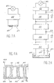
- FIGS. 1A to 1C A schematic description of devices corresponding is given in FIGS. 1A to 1C.
- FIG. 1A represents a machine for Stirling.
- a compressor 1 or pressure oscillator consists of a piston actuated mechanically by a crankshaft 2.
- the machine of Gifford and Mac Mahon illustrated in FIG. 1B, is characterized by a compressor gas 3 with low pressure inlet 4 and outlet 5 high pressure, permanent and connected to the machine refrigeration proper 10 by an inlet valve 6 and an outlet valve 7 respectively, which are open in turn to generate cycles of pressure required.
- the refrigerating machine 10 which is connected to these compressors 1 and 3 is the same in both cases. It consists of a tube 9 in which slides a displacer piston 11 which divides the contents of tube 9 into two variable volume chambers, interconnected by a bypass 12, on which a regenerator of heat 13 is installed.
- the room connected to compressor 1 or 3 is at temperature T2 (corresponding to the hot spring), and the other room is at temperature T3 of the cold source.
- the piston displacer 11 passes the compressed gas from the chamber at temperature T2, to the room at temperature T3, by exchanging its heat with the regenerator of heat 13 in response to pressure rises in the compressor.
- Gas expansion is produced when he mainly occupies the room at the temperature T3, then the gas is heated by crossing the heat regenerator 13 to the chamber temperature T2 before undergoing a new cycle.
- the heat regenerator 13 has the property of return to the gas flowing in one direction the heat that it took previously from the gas flowing in the direction reverse.
- the room at temperature T2 communicates with the compressor 3 via input 4 and output 5; in the realizations of FIG. 1A, the connection of the compressor 1 at the compressor chamber at temperature T2 east produced by a single pressure test pipe 15.
- the machines thus alternative are the seat of two periodic waves in the volume of trigger 15, one of pressure and the other of flow. he is possible to control the phase shift of these two waves by mechanical means which control the movements of the compressor piston 1 or of the valves 6 and 7, usually at room temperature, and the piston displacer 11 which can, for applications in cryogenics, having to operate at very low temperatures. We then actually arrive at the sought-after situation where maximum relaxation, i.e. maximum heat absorption, is simultaneous at the maximum gas flow in the cold source T3.
- maximum relaxation i.e. maximum heat absorption
- Figure 1C illustrates a tube machine pulsation. It includes a pressure oscillator 16, symbolized by a mechanical compressor, a regenerator heat 17 connected to the compressor 16 by a pressure tap 18 and a pulsation tube 19 which connects to the end of the heat regenerator 17 opposite to the pressure oscillator 16.
- the pressure tube pulse 19 is closed at the opposite end to the heat regenerator 17.
- the pulsation tube 19 is throttled near the heat regenerator 17, where the cold source SF is located, while the hot source SC is located at the opposite end of the pulsation 19, at the end of an enlarged portion and by cylindrical example of it.
- the gas column is maintained oscillations, and the dimensions and the shape of the various elements of the device allow to choose the operating frequency to obtain the phase shift of the flow waves and pressure which effectively extracts from the heat at the cold source, to transfer it to the hot spring.
- the Brayton cycle ( Figure 2A) can operate with nitrogen if the desired cold source 25 is at a temperature above 80 Kelvin. For lower temperatures, the cycle gas will generally helium.
- Claude's cycle in Figure 2A corresponds rather than a helium cycle, whose cold source 26 is a liquid helium bath.
- Relaxation without work or enthalpy constant does not absorb heat, but it is generally used in the immediate vicinity of the fluid saturation curve to achieve the phase change by expansion of the gas which is partially liquefied.
- the trigger with phase change is at proscribe to avoid mechanical destruction, either the turbine unbalanced by droplets, or piston subjected to the "blows" of the liquid which risks being there accumulate.
- the expansion turbines must rotate at high speeds, several dozen or more hundreds of thousands of revolutions per minute, and are generally supported by non-contact bearings, most often gas.
- the piston regulators are, a priori, better suitable as turbines for processing flows reduced, but their reliability is strongly conditioned by achieving friction sealing between piston and cylinder, and by the existence of valves cold with associated control mechanisms.
- the object of the invention relates to a solution original for making machines fluid cooling by expansion, in particular cryogenic (either isentropic or, if necessary, isothermal) better suited than turbines and machines piston to treat low flows with good efficiency, and good reliability, while being insensitive to the presence of liquid or fluid in double phase.
- cryogenic either isentropic or, if necessary, isothermal
- This device reduces the temperature fluid thanks to the expansion carried out in the relaxation compartment. There is therefore cooling of the fluid as soon as it leaves this compartment.
- the invention implements parts in movement without contact and without recourse to valves.
- This device is compatible with miniaturization to handle low flow rates.
- it can accept, without any problem, the formation of fluid two-phase during expansion.
- he may have at least one circuit in one of the spirals heat exchange allowing to tend towards isothermal conditions.
- means may be provided for control the speed of rotation of the moving spiral during its movement.
- the movable spiral can be linked to a part around which an eccentric sleeve is in rotation, a part linked to the eccentric sleeve able to support the rotor of an electric brake.
- This socket can be done with, on at least one of its two faces, a bearing contactless, magnetic or gas type.
- a means of controlling the axial play between the two spirals can be provided.
- Spirals can be, for example, Archimedes' spirals or defined by a succession of arcs of a circle.
- a fluid expansion system may include at least two trigger stages, each with a device according to one of the forms described above.
- a common tree can possibly allow a movement in phase of the moving spirals of the different trigger devices.
- a cryogenic expansion machine can therefore include a compressor, an exchanger and a device or an expansion system as described above.
- the principle of the invention is based on the use of a relaxation compartment comprising, as illustrated in FIGS. 3A to 3D and 4A, a first fixed spiral 28 and a second spiral 30 arranged mobile inside the first.
- Each spiral rests or is linked to a bottom flat 32, 34.
- the gas to be expanded is introduced through a tube 36.
- An exhaust may be provided. So, reduced clearances 40, 42, provided between the game upper partitions 28, 30 of the spirals and the flat bottoms 32, 34 allow the fluid to escape the outside of the movable spiral, then of the spiral fixed (arrow referenced 44 in Figure 4).
- Gas can only flow by increasing by volume (expansion) and by exerting a force on the wall mobile 30 (work), subjected to a movement of circular translation. Because of this movement, each point of the spiral 30 describes a circle, the part mobile permanently remaining parallel to itself.
- Figures 3A to 3D illustrate the process gas expansion in different stages, by which we can follow the evolution of a fraction of the gas, quarter turn to quarter turn. This gas passes by the continuously increasing volumes 46, 48, 50, 52, then finally 54, before exhaust.
- the volume of gas during expansion is at each moment limited by a partition of the spiral fixed and a partition of the movable spiral, which become tangent every 180 degrees, following their developed.
- the circular translation movement returns to drag the tangency points along the fixed spiral profile, allowing gas considered to move from the center to the outside of the spiral increasing in volume.
- FIG. 3E An example of realization with several spirals is illustrated in Figure 3E.
- Two fixed spirals 27 and 29 are arranged symmetrical, at 180 ° with respect to an axis of symmetry ⁇ .
- Two movable spirals 31 and 33 alternately become tangent on a face with the spiral 27 and on the other face with the spiral 29.
- the thicknesses of the partitions of the spirals can be chosen constant or variable for optimize their mechanical strength and footprint.
- the materials that can be used will satisfy preferably on condition that the two pieces (fixed and mobile) are compatible, from the point of view of their dilation, so that the reduced clearances are obtained at nominal operating conditions at low temperature.
- materials with low expansion such as fiber composites carbon, or metal alloys (like Invar).
- the copper or aluminum will be more favorable.
- materials with low density such as titanium or light alloys, strong enough to limit forces of inertia and the associated deformations.
- Plastic materials can also be used. They can come in massive form. They can also be locally reported (in the form of superficial segments or deposits), either for limit the effects of possible friction, either to obtain, by progressive wear, a running-in effect causing the pieces to adapt their shape to one the other. We will preferably try to reach the best compromise between poor contact and low leakage.
- the device flow can be adjusted by adjustment of its rotation speed.
- means for adjusting the speed of rotation can be provided. Examples will be given later.
- a device according to the invention can work at slow speed. For a fixed flow, a slow speed will bring more room usage bulky, therefore less sensitive to miniaturization to handle low flow rates.
- a decisive advantage of the invention results his ability to accept without any contraindication the formation, by relaxation, of fluid two-phase, whose liquid phase can possibly be evacuated to the exhaust without difficulty.
- FIGS. 4B and 4C Variants of the device of FIG. 4A are given in FIGS. 4B and 4C.
- a coil cold source 35 is fixed against the flat bottom 34 of the fixed spiral.
- a cold source 37 is integrated into the walls of the fixed spiral: a fluid can therefore circulate in these walls.
- FIG. 5 shows a cryogenic expansion valve whose fixed parts are supported by a structure 50 which carries two shafts 52, 63 to eccentric.
- the shaft 52 centered on the bearings 53 comprises an electric brake composed of a rotor 54 and a stator 55 to control the speed of rotation and extract the trigger work toward a adaptable load receiver 56.
- the shaft 52 is provided with two eccentric axes 57 and 58 which allow, through bearings 59 and 60 and an arm 62, a link mechanical with a movable plate 61.
- the arm 62 allowing a very stable and precise positioning.
- the mass of this arm can, moreover, be chosen for bring the center of gravity of the mobile assembly to desired level.
- the movable plate 61 is linked by the second eccentric shaft 63 mounted on ball bearings 64 and 65.
- the movement of this tree 63 is in phase with that of shaft 52, so that the movement of the plate 61 is a circular translation, without rotation.
- All the mechanical parts described above operate at room temperature in a housing 66 and a plate 67, which contain the fluid cycle 68.
- the latter can be, for example, helium at the exhaust pressure of the regulator, close to atmospheric pressure.
- Compressed gas 69 does a job by putting in movement the movable spiral 70 and the plate 61, both attached to at least one connecting element 71.
- the plate and fixed spiral 72, carried by a tube 73, are protected from external heat by a enclosure 74, which also allows vacuuming volume 75 by conventional means, not represented.
- the connecting elements 71 and the tube 73 have one hot end and one cold end. They are preferably sized to be mechanically rigid, while causing thermal leakage minimum to the gas circuit to be expanded.
- An auxiliary cooling circuit 76 for example supplied with liquid nitrogen around 80 K, allows reduce thermal leaks to trays 70 and 72.
- a helium liquefier with cycle of Claude such as that illustrated in FIG. 2B of the regulators of the type of that of FIG. 5 can be used with gas 69 and trays 70 and 72 working, on the first floor, around 50 to 60 Kelvin or, on the second floor, around 15 to 20 Kelvin.
- auxiliary circuit 76 will be preferably supplied by the previous stages at 50 K or 20 K.
- the movable spiral Under the effect of gas expansion 69 in the spiral compartment 70, 72, the movable spiral is driven in motion. The latter is transmitted by the connecting elements 71, to the plate 61.
- the trees eccentric 52, 63 in phase, block the own rotation component of the movement of the moving spiral. There remains the translational movement rotary of the latter, therefore of the plate 61 and the arm 62. Thanks to the eccentric axes 57, 58, the shaft 52 is rotated.
- the electric brake (stator 55 and rotor 54) makes it possible to control the speed of this rotation, therefore of the rotation of axes 57, 58 and therefore the speed of the rotary translational movement of the movable spiral 70.
- deformable elements such that a network of fibers or springs, one end of each fiber or spring being fixed to the movable spiral or at its flat bottom, while the other end is linked to the fixed part of the device.
- FIG. 6 A solution, implementing an element deformable, is illustrated in figure 6.
- the spiral mobile 77 is linked by connecting elements 78 to a movable plate 79 whose own rotation is blocked by a bellows 83.
- the latter is fixed, at its part lower, to plate 79, and at its upper part, to a fixed part 84 of the device.
- the bellows allows besides separating the atmosphere from part 86 of the enclosure, where lubricant vapors can exist, from part 87 of the gas enclosure high purity cycle.
- a shaft 80 with eccentric 85 fixes the circular translation stroke of the plate 79.
- This shaft 80 is rotated about its axis 88, fixed relative to the device.
- Axis 85 is rotating around the fixed axis 88.
- the shaft 80 can support also the rotor 81 of an electric brake, the stator is designated by reference 82.
- the device is, moreover, identical or similar to that described above in conjunction with Figure 5.
- Another solution implements means magnetic, exerting forces such as translation can take place by prohibiting the rotation.
- the moving part 88 or rather the flat bottom, or from above, the movable spiral is integral with a bar 89, either ferromagnetic or magnetized permed. Both are placed in the field magnetic of an external dipole 90 whose lines of Parallel fields set the orientation of the room.
- the moving part 88 and its bar 89 are represented in three different positions. These parts can be linked to a tray such as the plate 79 of FIG. 6, the latter being itself guided by a single eccentric, as described above in conjunction with this same figure 6.
- Fixed base 91 supports the brake stator 92 and the hot end of a bellows 93. The latter is intended for blocking the rotation of the moving spiral 94.
- the mobile part is made up of the plate central 95 connected to the movable spiral 94 by the connecting elements 96.
- An eccentric sleeve 97 free to rotate, is centered in the base 91 by the bearing 99 and supports the central plate 95 by means of the bearing 98.
- Dynamic balancing is obtained, on the one hand by a wedge 100 which allows to bring in the plane of bearings 98 and 99 the center of gravity of the assembly mobile 94, 96, 95, 100 and, on the other hand, by shims 101 and 102, which allow you to balance all inertias applied horizontally inside the bearing 99.
- cryogenic bearings without contact for example magnetic bearings or bearings with gas
- This solution has the advantage of greater mechanical rigidity to ensure better control of the respective position of fixed and mobile spirals intended for implementation of the invention.
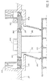
- FIG. 9 shows a helium regulator at 7 K and approximately 15 bars which, for trigger, will go out of the spiral towards 4.5 K, under 1 bar, in double phase, with a high proportion of liquid.
- the gas to be expanded enters via line 111 to 7 Kelvin, he provides his work between the fixed spiral 112 and the moving spiral 113, before going out under form of liquid-vapor mixture via line 134.
- the moving equipment activated by the spiral 113, is connected by the connecting elements 115 to the plate 116 which rotates the eccentric sleeve 117, maintained in an axial position by the link 118 at ball bearing 119 located in the hot part, at 300 K, which is braked and speed controlled by the electric brake 120.
- the plate 116 is blocked in rotation by the bellows 121, itself fixed to the hot casing 122.
- the rotation of the socket 117 allows maintain, on both sides, two gas bearings 123 and 124 hydrodynamics, which provide movement without contact inside cryostat 125.
- This cryostat is protected from parasitic heat inputs by auxiliary cooling circuits 126, which hold the plate 116 of the socket 117, and the bearings 123 and 124 as well as a heat shield 127, around 20 Kelvin and via circuit 128, supplied to 80 K in liquid nitrogen, which is connected to screen 129.
- the axial play between the two spirals 112 and 113 is preferably rigorously controlled to stay close to a few hundredths of a millimeter.
- This clearance measured by a cold position sensor 131, is controlled by a regulator 132 which acts on the electroaiman 133, by controlled attraction of a ferromagnetic plate 134.
- a regulator according to one of the modes of realization described above can be used for perform a Brayton cycle, as described in the introduction to this application, in conjunction with Figure 2A.
- the invention is not limited to the realization single stage regulators using only one pair of spirals, one being fixed and the other mobile.
- the same mechanical crew and the same suspension set can be used for the operation of several regulators.
- the same mechanical equipment can be used to operate a three-stage regulator shown in Figure 10, where we voluntarily combined in combination several of the variants described previously.
- the second floor works between 15 bars, 25 Kelvin (at point 143) and 1.2 bar, 15 Kelvin (at point point 144).
- the third stage receives (in 145) gas under 15 bars at 7 Kelvin, which comes out (in 146) at 4.4 K in liquid-gas mixture at 1.3 bar.
- a possible variant to make relaxation on the third more insulated floor could be coat the tray of the fixed spiral 171 with a condenser 180 where could condense directly from liquid helium supplying the cold source.
- the three movable spirals 147, 148, 149 are linked to the same tree 150, the sections of which are decreasing with the temperature level.
- the shaft 150 is integral with a plate 151, at room temperature, and a tray 152, at temperature equal to around 30 Kelvin.
- the plate 151 rotates the ring offset 153 mounted on ball bearings 154 and 155. This ring is speed controlled by the brake 156.
- the eccentric ring 157 is held in position by a vertical magnetic stop 158. It is centered radially by two gas bearings hydrodynamics 159 and 160 which could equally be replaced by magnetic bearings, i.e. permanent magnets, either superconductive, of a nature to be defined according to the temperature level.
- the gas circuits are separated from each other others by bellows 176 and 177.
- Another bellows 178 separates the cryogenic circuit from the casing 179 which can either operate at a different pressure or contain lubricant vapors if the bearings 154 and 155 are greased.
- Bellows 176, 177 and 178 contribute, by elsewhere, to fix the mobile assembly in rotation integral with the plates 151 and 152 and the shaft 150 to control the desired movement of translation circular.
- the example was given of a three-way regulator floors to carry out a cycle of Claude. It is possible to make a regulator with a number different stages (either two, or a number N> 3). Of even, it is possible to use any combination of various embodiments set out above.
- the respective position of the fixed and mobile spirals must, preferably be able to be adjusted precisely, to limit the play both in the axial direction and in the radial direction.
- the means of adjustment used remain completely classic and have not been represented to avoid weighing down the illustrations.
Applications Claiming Priority (3)
| Application Number | Priority Date | Filing Date | Title |
|---|---|---|---|
| FR9508608 | 1995-07-17 | ||
| FR9508608A FR2736999B1 (fr) | 1995-07-17 | 1995-07-17 | Machine de detente cryogenique a spirale |
| EP96925790A EP0839258A1 (de) | 1995-07-17 | 1996-07-16 | Spiralexpansionsanlage für kryogene temperaturen |
Related Parent Applications (1)
| Application Number | Title | Priority Date | Filing Date |
|---|---|---|---|
| EP96925790A Division EP0839258A1 (de) | 1995-07-17 | 1996-07-16 | Spiralexpansionsanlage für kryogene temperaturen |
Publications (2)
| Publication Number | Publication Date |
|---|---|
| EP1251278A2 true EP1251278A2 (de) | 2002-10-23 |
| EP1251278A3 EP1251278A3 (de) | 2003-05-21 |
Family
ID=9481038
Family Applications (2)
| Application Number | Title | Priority Date | Filing Date |
|---|---|---|---|
| EP96925790A Withdrawn EP0839258A1 (de) | 1995-07-17 | 1996-07-16 | Spiralexpansionsanlage für kryogene temperaturen |
| EP02077846A Withdrawn EP1251278A3 (de) | 1995-07-17 | 1997-02-06 | Spiralexpansionsanlage fÜr Kryogene Temperaturen |
Family Applications Before (1)
| Application Number | Title | Priority Date | Filing Date |
|---|---|---|---|
| EP96925790A Withdrawn EP0839258A1 (de) | 1995-07-17 | 1996-07-16 | Spiralexpansionsanlage für kryogene temperaturen |
Country Status (4)
| Country | Link |
|---|---|
| EP (2) | EP0839258A1 (de) |
| JP (1) | JPH11509597A (de) |
| FR (1) | FR2736999B1 (de) |
| WO (1) | WO1997004215A1 (de) |
Families Citing this family (4)
| Publication number | Priority date | Publication date | Assignee | Title |
|---|---|---|---|---|
| FR2764347B1 (fr) * | 1997-06-05 | 1999-07-30 | Alsthom Cge Alcatel | Machine du type scroll |
| JP4618478B2 (ja) * | 2001-08-01 | 2011-01-26 | 株式会社豊田自動織機 | スクロール型圧縮機 |
| RU2716780C1 (ru) * | 2019-07-29 | 2020-03-16 | Юрий Иванович Духанин | Турбодетандер |
| CN114033675A (zh) * | 2021-11-25 | 2022-02-11 | 合肥圣三松冷热技术有限公司 | 一种三级涡旋结构压缩机 |
Citations (8)
| Publication number | Priority date | Publication date | Assignee | Title |
|---|---|---|---|---|
| FR1596943A (de) * | 1967-12-18 | 1970-06-22 | ||
| US3817664A (en) * | 1972-12-11 | 1974-06-18 | J Bennett | Rotary fluid pump or motor with intermeshed spiral walls |
| DE3017045A1 (de) * | 1979-05-14 | 1980-11-27 | Aginfor Ag | Kreiskolben-maschine sowie verwendung derselben |
| US4291547A (en) * | 1978-04-10 | 1981-09-29 | Hughes Aircraft Company | Screw compressor-expander cryogenic system |
| FR2532011A1 (fr) * | 1982-08-20 | 1984-02-24 | Volkswagen Ag | Machine refoulante pour fluides compressibles |
| JPS59110894A (ja) * | 1982-12-15 | 1984-06-26 | Hitachi Ltd | スクロ−ル式流体機械 |
| EP0122722A1 (de) * | 1983-03-15 | 1984-10-24 | Sanden Corporation | Axialdichtung für eine Verdrängungsmaschine der Spiralbauart |
| US5391065A (en) * | 1993-10-26 | 1995-02-21 | Ingersoll-Rand Company | Parallel adjustment assembly for a scroll compressor |
Family Cites Families (3)
| Publication number | Priority date | Publication date | Assignee | Title |
|---|---|---|---|---|
| US4472120A (en) * | 1982-07-15 | 1984-09-18 | Arthur D. Little, Inc. | Scroll type fluid displacement apparatus |
| GB2132276B (en) * | 1982-12-23 | 1986-10-01 | Copeland Corp | Scroll-type rotary fluid-machine |
| CH672351A5 (de) * | 1986-12-24 | 1989-11-15 | Bbc Brown Boveri & Cie |
-
1995
- 1995-07-17 FR FR9508608A patent/FR2736999B1/fr not_active Expired - Fee Related
-
1996
- 1996-07-16 EP EP96925790A patent/EP0839258A1/de not_active Withdrawn
- 1996-07-16 WO PCT/FR1996/001102 patent/WO1997004215A1/fr not_active Application Discontinuation
- 1996-07-16 JP JP9506349A patent/JPH11509597A/ja not_active Ceased
-
1997
- 1997-02-06 EP EP02077846A patent/EP1251278A3/de not_active Withdrawn
Patent Citations (8)
| Publication number | Priority date | Publication date | Assignee | Title |
|---|---|---|---|---|
| FR1596943A (de) * | 1967-12-18 | 1970-06-22 | ||
| US3817664A (en) * | 1972-12-11 | 1974-06-18 | J Bennett | Rotary fluid pump or motor with intermeshed spiral walls |
| US4291547A (en) * | 1978-04-10 | 1981-09-29 | Hughes Aircraft Company | Screw compressor-expander cryogenic system |
| DE3017045A1 (de) * | 1979-05-14 | 1980-11-27 | Aginfor Ag | Kreiskolben-maschine sowie verwendung derselben |
| FR2532011A1 (fr) * | 1982-08-20 | 1984-02-24 | Volkswagen Ag | Machine refoulante pour fluides compressibles |
| JPS59110894A (ja) * | 1982-12-15 | 1984-06-26 | Hitachi Ltd | スクロ−ル式流体機械 |
| EP0122722A1 (de) * | 1983-03-15 | 1984-10-24 | Sanden Corporation | Axialdichtung für eine Verdrängungsmaschine der Spiralbauart |
| US5391065A (en) * | 1993-10-26 | 1995-02-21 | Ingersoll-Rand Company | Parallel adjustment assembly for a scroll compressor |
Non-Patent Citations (1)
| Title |
|---|
| PATENT ABSTRACTS OF JAPAN vol. 8, no. 230 (M-333) [1667], 23 octobre 1984 (1984-10-23) & JP 59 110894 A (HITACHI), 26 juin 1984 (1984-06-26) * |
Also Published As
| Publication number | Publication date |
|---|---|
| WO1997004215A1 (fr) | 1997-02-06 |
| EP0839258A1 (de) | 1998-05-06 |
| FR2736999B1 (fr) | 1997-08-22 |
| JPH11509597A (ja) | 1999-08-24 |
| EP1251278A3 (de) | 2003-05-21 |
| FR2736999A1 (fr) | 1997-01-24 |
Similar Documents
| Publication | Publication Date | Title |
|---|---|---|
| US5987894A (en) | Temperature lowering apparatus using cryogenic expansion with the aid of spirals | |
| JPH0444202A (ja) | 液化冷凍機付きクライオスタツト | |
| EP0614059B1 (de) | Kühler mit einem Schwingrohrkaltkopf | |
| EP0279739B1 (de) | Kältemaschine, insbesondere mit Vuilleumier-Zyklus, mit durch Gaslager unterstützten Kolben | |
| FR2638823A1 (fr) | Refrigerateur du type a accumulation du froid a etages multiples et dispositif de refroidissement comportant un tel refrigerateur | |
| FR2988695A1 (fr) | Dispositif et procede de remplissage de reservoir | |
| EP3414498A1 (de) | Kryogene kühlvorrichtung | |
| WO2021165042A1 (fr) | Dispositif et procédé de réfrigération à dilution | |
| CH664799A5 (fr) | Ensemble moteur-pompe a chaleur stirling a piston libre. | |
| EP1251278A2 (de) | Spiralexpansionsanlage fÜr Kryogene Temperaturen | |
| Fast | Advances in cryogenic engineering | |
| Garg et al. | Effect of Porosity of the regenerator on the performance of a miniature Stirling cryocooler | |
| EP4010645A1 (de) | Semipermeable membran mit aus einer flüchtigen substanz resultierenden poren | |
| Radebaugh | Microscale heat transfer at low temperatures | |
| FR2914050A1 (fr) | Refrigerateur a basse ou tres basse temperature et procede de refrigeration | |
| WO1997003327A1 (fr) | Refrigerateur ou pompe a chaleur a tube de pulsation alimente par un generateur de pression | |
| FR2742215A1 (fr) | Refroidisseur stirling a pilotage rotatif | |
| Wagner | Refrigeration | |
| Hong et al. | Development of Stirling-type pulse tube cryocooler | |
| Belrzaeg et al. | Overview of the Cryogenic Refrigeration Systems | |
| Muley et al. | Development of a helium recondensing cryostat | |
| WO2015121179A1 (fr) | Système de refroidissement de source chaude | |
| Hiratsuka et al. | Recent development status of stirling type pulse tube cryocooler for HTS | |
| Hiratsuka et al. | Development of orientation-free high power stirling-type pulse tube cryocooler | |
| Kim et al. | A Study of the CryoTel® DS 1.5 Cryocooler for Higher Cooling Capacity |
Legal Events
| Date | Code | Title | Description |
|---|---|---|---|
| PUAI | Public reference made under article 153(3) epc to a published international application that has entered the european phase |
Free format text: ORIGINAL CODE: 0009012 |
|
| AC | Divisional application: reference to earlier application |
Ref document number: 839258 Country of ref document: EP |
|
| AK | Designated contracting states |
Kind code of ref document: A2 Designated state(s): DE GB IT |
|
| PUAL | Search report despatched |
Free format text: ORIGINAL CODE: 0009013 |
|
| AK | Designated contracting states |
Designated state(s): DE GB IT |
|
| RIC1 | Information provided on ipc code assigned before grant |
Ipc: 7F 01C 21/16 B Ipc: 7F 01C 17/00 B Ipc: 7F 01C 17/06 B Ipc: 7F 01C 1/02 A |
|
| 17P | Request for examination filed |
Effective date: 20031024 |
|
| AKX | Designation fees paid |
Designated state(s): DE GB |
|
| STAA | Information on the status of an ep patent application or granted ep patent |
Free format text: STATUS: THE APPLICATION IS DEEMED TO BE WITHDRAWN |
|
| 18D | Application deemed to be withdrawn |
Effective date: 20060404 |