EP1251278A2 - Dispositif de detente à spirales pour des temperatures cryogéniques - Google Patents
Dispositif de detente à spirales pour des temperatures cryogéniques Download PDFInfo
- Publication number
- EP1251278A2 EP1251278A2 EP02077846A EP02077846A EP1251278A2 EP 1251278 A2 EP1251278 A2 EP 1251278A2 EP 02077846 A EP02077846 A EP 02077846A EP 02077846 A EP02077846 A EP 02077846A EP 1251278 A2 EP1251278 A2 EP 1251278A2
- Authority
- EP
- European Patent Office
- Prior art keywords
- spiral
- spirals
- rotation
- expansion
- linked
- Prior art date
- Legal status (The legal status is an assumption and is not a legal conclusion. Google has not performed a legal analysis and makes no representation as to the accuracy of the status listed.)
- Withdrawn
Links
Images


Classifications
-
- F—MECHANICAL ENGINEERING; LIGHTING; HEATING; WEAPONS; BLASTING
- F04—POSITIVE - DISPLACEMENT MACHINES FOR LIQUIDS; PUMPS FOR LIQUIDS OR ELASTIC FLUIDS
- F04C—ROTARY-PISTON, OR OSCILLATING-PISTON, POSITIVE-DISPLACEMENT MACHINES FOR LIQUIDS; ROTARY-PISTON, OR OSCILLATING-PISTON, POSITIVE-DISPLACEMENT PUMPS
- F04C23/00—Combinations of two or more pumps, each being of rotary-piston or oscillating-piston type, specially adapted for elastic fluids; Pumping installations specially adapted for elastic fluids; Multi-stage pumps specially adapted for elastic fluids
- F04C23/001—Combinations of two or more pumps, each being of rotary-piston or oscillating-piston type, specially adapted for elastic fluids; Pumping installations specially adapted for elastic fluids; Multi-stage pumps specially adapted for elastic fluids of similar working principle
- F04C23/003—Combinations of two or more pumps, each being of rotary-piston or oscillating-piston type, specially adapted for elastic fluids; Pumping installations specially adapted for elastic fluids; Multi-stage pumps specially adapted for elastic fluids of similar working principle having complementary function
-
- F—MECHANICAL ENGINEERING; LIGHTING; HEATING; WEAPONS; BLASTING
- F01—MACHINES OR ENGINES IN GENERAL; ENGINE PLANTS IN GENERAL; STEAM ENGINES
- F01C—ROTARY-PISTON OR OSCILLATING-PISTON MACHINES OR ENGINES
- F01C1/00—Rotary-piston machines or engines
- F01C1/02—Rotary-piston machines or engines of arcuate-engagement type, i.e. with circular translatory movement of co-operating members, each member having the same number of teeth or tooth-equivalents
- F01C1/0207—Rotary-piston machines or engines of arcuate-engagement type, i.e. with circular translatory movement of co-operating members, each member having the same number of teeth or tooth-equivalents both members having co-operating elements in spiral form
- F01C1/0215—Rotary-piston machines or engines of arcuate-engagement type, i.e. with circular translatory movement of co-operating members, each member having the same number of teeth or tooth-equivalents both members having co-operating elements in spiral form where only one member is moving
-
- F—MECHANICAL ENGINEERING; LIGHTING; HEATING; WEAPONS; BLASTING
- F01—MACHINES OR ENGINES IN GENERAL; ENGINE PLANTS IN GENERAL; STEAM ENGINES
- F01C—ROTARY-PISTON OR OSCILLATING-PISTON MACHINES OR ENGINES
- F01C1/00—Rotary-piston machines or engines
- F01C1/02—Rotary-piston machines or engines of arcuate-engagement type, i.e. with circular translatory movement of co-operating members, each member having the same number of teeth or tooth-equivalents
- F01C1/0207—Rotary-piston machines or engines of arcuate-engagement type, i.e. with circular translatory movement of co-operating members, each member having the same number of teeth or tooth-equivalents both members having co-operating elements in spiral form
- F01C1/0246—Details concerning the involute wraps or their base, e.g. geometry
-
- F—MECHANICAL ENGINEERING; LIGHTING; HEATING; WEAPONS; BLASTING
- F01—MACHINES OR ENGINES IN GENERAL; ENGINE PLANTS IN GENERAL; STEAM ENGINES
- F01C—ROTARY-PISTON OR OSCILLATING-PISTON MACHINES OR ENGINES
- F01C17/00—Arrangements for drive of co-operating members, e.g. for rotary piston and casing
- F01C17/06—Arrangements for drive of co-operating members, e.g. for rotary piston and casing using cranks, universal joints or similar elements
-
- F—MECHANICAL ENGINEERING; LIGHTING; HEATING; WEAPONS; BLASTING
- F01—MACHINES OR ENGINES IN GENERAL; ENGINE PLANTS IN GENERAL; STEAM ENGINES
- F01C—ROTARY-PISTON OR OSCILLATING-PISTON MACHINES OR ENGINES
- F01C20/00—Control of, monitoring of, or safety arrangements for, machines or engines
- F01C20/08—Control of, monitoring of, or safety arrangements for, machines or engines characterised by varying the rotational speed
-
- F—MECHANICAL ENGINEERING; LIGHTING; HEATING; WEAPONS; BLASTING
- F01—MACHINES OR ENGINES IN GENERAL; ENGINE PLANTS IN GENERAL; STEAM ENGINES
- F01C—ROTARY-PISTON OR OSCILLATING-PISTON MACHINES OR ENGINES
- F01C21/00—Component parts, details or accessories not provided for in groups F01C1/00 - F01C20/00
- F01C21/02—Arrangements of bearings
-
- F—MECHANICAL ENGINEERING; LIGHTING; HEATING; WEAPONS; BLASTING
- F04—POSITIVE - DISPLACEMENT MACHINES FOR LIQUIDS; PUMPS FOR LIQUIDS OR ELASTIC FLUIDS
- F04C—ROTARY-PISTON, OR OSCILLATING-PISTON, POSITIVE-DISPLACEMENT MACHINES FOR LIQUIDS; ROTARY-PISTON, OR OSCILLATING-PISTON, POSITIVE-DISPLACEMENT PUMPS
- F04C2220/00—Application
- F04C2220/22—Application for very low temperatures, i.e. cryogenic
-
- F—MECHANICAL ENGINEERING; LIGHTING; HEATING; WEAPONS; BLASTING
- F05—INDEXING SCHEMES RELATING TO ENGINES OR PUMPS IN VARIOUS SUBCLASSES OF CLASSES F01-F04
- F05B—INDEXING SCHEME RELATING TO WIND, SPRING, WEIGHT, INERTIA OR LIKE MOTORS, TO MACHINES OR ENGINES FOR LIQUIDS COVERED BY SUBCLASSES F03B, F03D AND F03G
- F05B2260/00—Function
- F05B2260/10—Particular cycles
-
- F—MECHANICAL ENGINEERING; LIGHTING; HEATING; WEAPONS; BLASTING
- F05—INDEXING SCHEMES RELATING TO ENGINES OR PUMPS IN VARIOUS SUBCLASSES OF CLASSES F01-F04
- F05C—INDEXING SCHEME RELATING TO MATERIALS, MATERIAL PROPERTIES OR MATERIAL CHARACTERISTICS FOR MACHINES, ENGINES OR PUMPS OTHER THAN NON-POSITIVE-DISPLACEMENT MACHINES OR ENGINES
- F05C2251/00—Material properties
- F05C2251/04—Thermal properties
- F05C2251/042—Expansivity
- F05C2251/044—Expansivity similar
Abstract
Description
- un compresseur 20 recycle le gaz du niveau de basse pression (BP), habituellement voisin de la pression atmosphérique, jusqu'au niveau de haute pression, généralement compris entre 15 et 30 bars environ,
- un ou des échangeurs de chaleur 22 à contre-courant assurent le prérefroidissement du gaz comprimé par échange avec le gaz à basse pression,
- une ou des machines de détente 23 sont la ou les véritables sources de production frigorifique. On utilise, soit des machines 23 dans lesquelles le gaz fournit un travail mécanique, soit de simples étranglements ou vannes de détente 24 où le gaz subit une perte de charge.
- une première spirale,
- une seconde spirale disposée à l'intérieur de cette première spirale,
- des moyens pour permettre un mouvement de translation circulaire, sans rotation propre, de la seconde spirale à l'intérieur de la première, lors de la détente d'un fluide, et
- des moyens pour contrôler la vitesse de rotation de la spirale mobile lors de son mouvement.
- deux arbres excentrés, chacun étant lié à la spirale mobile par une extrémité en rotation autour d'un axe fixe par rapport au dispositif,
- ou au moins une pièce déformable liée par une de ses extrémités à une partie fixe du dispositif et dont l'autre extrémité est liée à la spirale mobile,
- ou des moyens magnétiques exerçant sur la spirale mobile ou sur une partie fixe par rapport à la spirale mobile, des forces telles que la translation puisse avoir lieu en interdisant toute rotation.
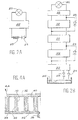
- la figure 1A à 1C illustrent respectivement des machines de Stirling, Gifford et à tube de pulsation,
- les figures 2A et 2B illustrent des machines de Brayton et de Claude,
- les figures 3A à 3D illustrent le principe de fonctionnement d'un compartiment de détente d'un dispositif selon l'invention,
- la figure 3E représente un mode de réalisation avec 4 spirales,
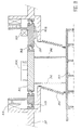
- les figures 4A à 4C représentent une vue en coupe d'un compartiment de détente d'un dispositif soit adiabatique soit isotherme selon l'invention,
- la figure 5 représente une première réalisation de l'invention,
- les figures 6 à 9 représentent d'autres réalisations de l'invention,
- la figure 10 représente un détendeur à trois étages, conforme à l'invention.
- les profils en spirale pourront être des spirales d'Archimède (le rayon R d'une telle spirale varie linéairement avec l'angle à partir d'un même centre (R=a)),
- les profils pourront être définis par une succession d'arcs de cercle, de centres différents et de rayons différents, soit par exemple à chaque demi-tour, soit encore à chaque quart de tour.
Claims (29)
- Dispositif d'abaissement de température par détente de fluide à l'état gazeux ou liquide ou en double phase, caractérisé en ce qu'il comporte un compartiment de détente comprenant :une première spirale (28, 72, 112, 171, 172, 173),une seconde spirale (30, 70, 77, 94, 113, 147, 148, 149) disposée à l'intérieur de cette première spirale,des moyens (52, 63 ; 80, 83, 85 ; 93, 95, 97 ; 116, 117, 121) pour permettre un mouvement de translation circulaire, sans rotation propre, de la seconde spirale à l'intérieur de la première, lors de la détente d'un fluide, etdes moyens (55, 82, 92, 120, 156) pour contrôler la vitesse de rotation de la spirale mobile lors de son mouvement.
- Dispositif selon la revendication 1, les moyens permettant un mouvement de translation circulaire, sans rotation propre, comportant deux arbres à excentrique (52, 63), chacun étant lié à la spirale mobile (170) par une extrémité en rotation autour d'un axe fixe par rapport au dispositif.
- Dispositif selon la revendication 1, les moyens permettant un mouvement de translation circulaire, sans rotation propre, comportant au moins une pièce déformable (83, 93, 121) liée par une de ses extrémités à une partie fixe (84, 122) du dispositif, et dont l'autre extrémité est liée à la spirale mobile (77, 94, 113).
- Dispositif selon la revendication 3, la ou les pièces déformables comportant un soufflet (83, 93, 121, 176-178), un réseau de fibres ou de ressorts.
- Dispositif selon la revendication 1, les moyens permettant un mouvement de translation circulaire, sans rotation propre, étant des moyens magnétiques (90) exerçant sur la spirale mobile ou sur une partie fixe (88) par rapport à la spirale mobile, des forces telles que la translation puisse avoir lieu en interdisant toute rotation.
- Dispositif selon la revendication 5, la pièce mobile (88) étant solidaire d'au moins un élément (89) ferromagnétique ou à aimantation permanente, des moyens étant prévus pour générer une aimantation dont les lignes de champ fixent l'orientation de la pièce mobile.
- Dispositif selon l'une des revendications 3 à 6, comportant en outre un arbre à excentrique (80) lié à la spirale mobile (77) par une extrémité en rotation autour d'un axe fixe par rapport au dispositif.
- Dispositif selon l'une des revendications 3 à 6, la spirale mobile étant liée à une pièce autour de laquelle une douille excentrique est en rotation.
- Dispositif selon la revendication 2, un des excentriques (52) portant le rotor (54) d'un frein électrique, le stator (55) étant fixe par rapport au dispositif.
- Dispositif selon la revendication 7, l'arbre à excentrique (80) supportant le rotor (81) d'un frein électrique, dont le stator (82) est fixe par rapport au dispositif.
- Dispositif selon la revendication 8, une pièce liée à la douille excentrique (97) supportant le rotor d'un frein électrique, dont le stator (92) est fixe par rapport au dispositif.
- Dispositif selon l'une des revendications 8 ou 11, la rotation de la douille se faisant sur au moins une de ses deux faces par un palier (123, 124, 159, 160) sans contact.
- Dispositif selon la revendication 12, le palier étant du type magnétique.
- Dispositif selon la revendication 12, le palier étant du type à gaz.
- Dispositif selon l'une des revendications 12 à 14, comportant en outre un moyen de contrôle du jeu axial entre les deux spirales.
- Dispositif selon l'une des revendications 11 à 15, la rotation de la douille ayant lieu dans un cryostat.
- Dispositif selon l'une des revendications 1 à 16, les spirales étant des spirales d'Archimède.
- Dispositif selon l'une des revendications 1 à 16, les spirales étant définies par une succession d'arcs de cercle.
- Dispositif selon l'une des revendications 1 à 18, les cloisons des spirales étant à hauteur variable.
- Dispositif selon l'une des revendications 1 à 19, chaque spirale étant liée à un fond plat (32, 34).
- Dispositif selon la revendication 20, un jeu réduit étant assuré, au moins à la température de fonctionnement du dispositif, entre la partie supérieure de la cloison d'une spirale et le fond plat de l'autre spirale.
- Dispositif selon l'une des revendications 1 à 21, les matériaux dont sont constitués les deux spirales étant à faible coefficient de dilatation thermique.
- Dispositif selon la revendication 22, les spirales comportant un matériau composite à fibre de carbone ou un alliage métallique.
- Dispositif selon l'une des revendications 1 à 23, des matériaux plastiques étant utilisés, au moins localement, au moins dans la partie d'une des deux spirales située en regard du fond (32, 34) de l'autre spirale.
- Dispositif selon l'une des revendications 1 à 24 utilisant dans au moins une des spirales un circuit d'échange de chaleur en liaison avec la source froide pour rendre la détente plus isotherme.
- Système de détente de fluide, comportant au moins deux étages de détente, chaque étage comportant un dispositif selon l'une des revendications 1 à 25.
- Système selon la revendication 26, un arbre commun (150) permettant un mouvement en phase des spirales mobiles (147, 148, 149) des différents dispositifs de détente.
- Machine de détente cryogénique comportant un compresseur (20), un échangeur de chaleur (22) et un dispositif de détente selon l'une des revendications 1 à 25.
- Machine de détente cryogénique comportant un compresseur (20), des échangeurs de chaleur (22) et un système de détente selon l'une des revendications 26 ou 27.
Applications Claiming Priority (3)
| Application Number | Priority Date | Filing Date | Title |
|---|---|---|---|
| FR9508608 | 1995-07-17 | ||
| FR9508608A FR2736999B1 (fr) | 1995-07-17 | 1995-07-17 | Machine de detente cryogenique a spirale |
| EP96925790A EP0839258A1 (fr) | 1995-07-17 | 1996-07-16 | Dispositif de detente a spirales pour des temperatures cryogeniques |
Related Parent Applications (1)
| Application Number | Title | Priority Date | Filing Date |
|---|---|---|---|
| EP96925790A Division EP0839258A1 (fr) | 1995-07-17 | 1996-07-16 | Dispositif de detente a spirales pour des temperatures cryogeniques |
Publications (2)
| Publication Number | Publication Date |
|---|---|
| EP1251278A2 true EP1251278A2 (fr) | 2002-10-23 |
| EP1251278A3 EP1251278A3 (fr) | 2003-05-21 |
Family
ID=9481038
Family Applications (2)
| Application Number | Title | Priority Date | Filing Date |
|---|---|---|---|
| EP96925790A Withdrawn EP0839258A1 (fr) | 1995-07-17 | 1996-07-16 | Dispositif de detente a spirales pour des temperatures cryogeniques |
| EP02077846A Withdrawn EP1251278A3 (fr) | 1995-07-17 | 1997-02-06 | Dispositif de detente à spirales pour des temperatures cryogéniques |
Family Applications Before (1)
| Application Number | Title | Priority Date | Filing Date |
|---|---|---|---|
| EP96925790A Withdrawn EP0839258A1 (fr) | 1995-07-17 | 1996-07-16 | Dispositif de detente a spirales pour des temperatures cryogeniques |
Country Status (4)
| Country | Link |
|---|---|
| EP (2) | EP0839258A1 (fr) |
| JP (1) | JPH11509597A (fr) |
| FR (1) | FR2736999B1 (fr) |
| WO (1) | WO1997004215A1 (fr) |
Families Citing this family (4)
| Publication number | Priority date | Publication date | Assignee | Title |
|---|---|---|---|---|
| FR2764347B1 (fr) * | 1997-06-05 | 1999-07-30 | Alsthom Cge Alcatel | Machine du type scroll |
| JP4618478B2 (ja) * | 2001-08-01 | 2011-01-26 | 株式会社豊田自動織機 | スクロール型圧縮機 |
| RU2716780C1 (ru) * | 2019-07-29 | 2020-03-16 | Юрий Иванович Духанин | Турбодетандер |
| CN114033675A (zh) * | 2021-11-25 | 2022-02-11 | 合肥圣三松冷热技术有限公司 | 一种三级涡旋结构压缩机 |
Citations (8)
| Publication number | Priority date | Publication date | Assignee | Title |
|---|---|---|---|---|
| FR1596943A (fr) * | 1967-12-18 | 1970-06-22 | ||
| US3817664A (en) * | 1972-12-11 | 1974-06-18 | J Bennett | Rotary fluid pump or motor with intermeshed spiral walls |
| DE3017045A1 (de) * | 1979-05-14 | 1980-11-27 | Aginfor Ag | Kreiskolben-maschine sowie verwendung derselben |
| US4291547A (en) * | 1978-04-10 | 1981-09-29 | Hughes Aircraft Company | Screw compressor-expander cryogenic system |
| FR2532011A1 (fr) * | 1982-08-20 | 1984-02-24 | Volkswagen Ag | Machine refoulante pour fluides compressibles |
| JPS59110894A (ja) * | 1982-12-15 | 1984-06-26 | Hitachi Ltd | スクロ−ル式流体機械 |
| EP0122722A1 (fr) * | 1983-03-15 | 1984-10-24 | Sanden Corporation | Dispositif d'étanchéité axiale pour un appareil à volutes de déplacement de fluide |
| US5391065A (en) * | 1993-10-26 | 1995-02-21 | Ingersoll-Rand Company | Parallel adjustment assembly for a scroll compressor |
Family Cites Families (3)
| Publication number | Priority date | Publication date | Assignee | Title |
|---|---|---|---|---|
| US4472120A (en) * | 1982-07-15 | 1984-09-18 | Arthur D. Little, Inc. | Scroll type fluid displacement apparatus |
| GB2132276B (en) * | 1982-12-23 | 1986-10-01 | Copeland Corp | Scroll-type rotary fluid-machine |
| CH672351A5 (fr) * | 1986-12-24 | 1989-11-15 | Bbc Brown Boveri & Cie |
-
1995
- 1995-07-17 FR FR9508608A patent/FR2736999B1/fr not_active Expired - Fee Related
-
1996
- 1996-07-16 EP EP96925790A patent/EP0839258A1/fr not_active Withdrawn
- 1996-07-16 WO PCT/FR1996/001102 patent/WO1997004215A1/fr not_active Application Discontinuation
- 1996-07-16 JP JP9506349A patent/JPH11509597A/ja not_active Ceased
-
1997
- 1997-02-06 EP EP02077846A patent/EP1251278A3/fr not_active Withdrawn
Patent Citations (8)
| Publication number | Priority date | Publication date | Assignee | Title |
|---|---|---|---|---|
| FR1596943A (fr) * | 1967-12-18 | 1970-06-22 | ||
| US3817664A (en) * | 1972-12-11 | 1974-06-18 | J Bennett | Rotary fluid pump or motor with intermeshed spiral walls |
| US4291547A (en) * | 1978-04-10 | 1981-09-29 | Hughes Aircraft Company | Screw compressor-expander cryogenic system |
| DE3017045A1 (de) * | 1979-05-14 | 1980-11-27 | Aginfor Ag | Kreiskolben-maschine sowie verwendung derselben |
| FR2532011A1 (fr) * | 1982-08-20 | 1984-02-24 | Volkswagen Ag | Machine refoulante pour fluides compressibles |
| JPS59110894A (ja) * | 1982-12-15 | 1984-06-26 | Hitachi Ltd | スクロ−ル式流体機械 |
| EP0122722A1 (fr) * | 1983-03-15 | 1984-10-24 | Sanden Corporation | Dispositif d'étanchéité axiale pour un appareil à volutes de déplacement de fluide |
| US5391065A (en) * | 1993-10-26 | 1995-02-21 | Ingersoll-Rand Company | Parallel adjustment assembly for a scroll compressor |
Non-Patent Citations (1)
| Title |
|---|
| PATENT ABSTRACTS OF JAPAN vol. 8, no. 230 (M-333) [1667], 23 octobre 1984 (1984-10-23) & JP 59 110894 A (HITACHI), 26 juin 1984 (1984-06-26) * |
Also Published As
| Publication number | Publication date |
|---|---|
| WO1997004215A1 (fr) | 1997-02-06 |
| EP0839258A1 (fr) | 1998-05-06 |
| FR2736999B1 (fr) | 1997-08-22 |
| JPH11509597A (ja) | 1999-08-24 |
| EP1251278A3 (fr) | 2003-05-21 |
| FR2736999A1 (fr) | 1997-01-24 |
Similar Documents
| Publication | Publication Date | Title |
|---|---|---|
| US5987894A (en) | Temperature lowering apparatus using cryogenic expansion with the aid of spirals | |
| JPH0444202A (ja) | 液化冷凍機付きクライオスタツト | |
| EP0614059B1 (fr) | Refroidisseur muni d'un doigt froid du type tube pulsé | |
| EP0279739B1 (fr) | Réfrigérateur, notamment à cycle de Vuilleumier, comportant des pistons suspendus par des paliers à gaz | |
| FR2638823A1 (fr) | Refrigerateur du type a accumulation du froid a etages multiples et dispositif de refroidissement comportant un tel refrigerateur | |
| FR2988695A1 (fr) | Dispositif et procede de remplissage de reservoir | |
| EP3414498A1 (fr) | Dispositif de réfrigération cryogénique | |
| WO2021165042A1 (fr) | Dispositif et procédé de réfrigération à dilution | |
| CH664799A5 (fr) | Ensemble moteur-pompe a chaleur stirling a piston libre. | |
| EP1251278A2 (fr) | Dispositif de detente à spirales pour des temperatures cryogéniques | |
| Fast | Advances in cryogenic engineering | |
| Garg et al. | Effect of Porosity of the regenerator on the performance of a miniature Stirling cryocooler | |
| EP4010645A1 (fr) | Membrane semi-perméable avec des pores résultant d'une substance volatile | |
| Radebaugh | Microscale heat transfer at low temperatures | |
| FR2914050A1 (fr) | Refrigerateur a basse ou tres basse temperature et procede de refrigeration | |
| WO1997003327A1 (fr) | Refrigerateur ou pompe a chaleur a tube de pulsation alimente par un generateur de pression | |
| FR2742215A1 (fr) | Refroidisseur stirling a pilotage rotatif | |
| Wagner | Refrigeration | |
| Hong et al. | Development of Stirling-type pulse tube cryocooler | |
| Belrzaeg et al. | Overview of the Cryogenic Refrigeration Systems | |
| Muley et al. | Development of a helium recondensing cryostat | |
| WO2015121179A1 (fr) | Système de refroidissement de source chaude | |
| Hiratsuka et al. | Recent development status of stirling type pulse tube cryocooler for HTS | |
| Hiratsuka et al. | Development of orientation-free high power stirling-type pulse tube cryocooler | |
| Kim et al. | A Study of the CryoTel® DS 1.5 Cryocooler for Higher Cooling Capacity |
Legal Events
| Date | Code | Title | Description |
|---|---|---|---|
| PUAI | Public reference made under article 153(3) epc to a published international application that has entered the european phase |
Free format text: ORIGINAL CODE: 0009012 |
|
| AC | Divisional application: reference to earlier application |
Ref document number: 839258 Country of ref document: EP |
|
| AK | Designated contracting states |
Kind code of ref document: A2 Designated state(s): DE GB IT |
|
| PUAL | Search report despatched |
Free format text: ORIGINAL CODE: 0009013 |
|
| AK | Designated contracting states |
Designated state(s): DE GB IT |
|
| RIC1 | Information provided on ipc code assigned before grant |
Ipc: 7F 01C 21/16 B Ipc: 7F 01C 17/00 B Ipc: 7F 01C 17/06 B Ipc: 7F 01C 1/02 A |
|
| 17P | Request for examination filed |
Effective date: 20031024 |
|
| AKX | Designation fees paid |
Designated state(s): DE GB |
|
| STAA | Information on the status of an ep patent application or granted ep patent |
Free format text: STATUS: THE APPLICATION IS DEEMED TO BE WITHDRAWN |
|
| 18D | Application deemed to be withdrawn |
Effective date: 20060404 |