EP1251278A2 - Scroll decompression device for cryogenic temperatures - Google Patents
Scroll decompression device for cryogenic temperatures Download PDFInfo
- Publication number
- EP1251278A2 EP1251278A2 EP02077846A EP02077846A EP1251278A2 EP 1251278 A2 EP1251278 A2 EP 1251278A2 EP 02077846 A EP02077846 A EP 02077846A EP 02077846 A EP02077846 A EP 02077846A EP 1251278 A2 EP1251278 A2 EP 1251278A2
- Authority
- EP
- European Patent Office
- Prior art keywords
- spiral
- spirals
- rotation
- expansion
- linked
- Prior art date
- Legal status (The legal status is an assumption and is not a legal conclusion. Google has not performed a legal analysis and makes no representation as to the accuracy of the status listed.)
- Withdrawn
Links
Images


Classifications
-
- F—MECHANICAL ENGINEERING; LIGHTING; HEATING; WEAPONS; BLASTING
- F04—POSITIVE - DISPLACEMENT MACHINES FOR LIQUIDS; PUMPS FOR LIQUIDS OR ELASTIC FLUIDS
- F04C—ROTARY-PISTON, OR OSCILLATING-PISTON, POSITIVE-DISPLACEMENT MACHINES FOR LIQUIDS; ROTARY-PISTON, OR OSCILLATING-PISTON, POSITIVE-DISPLACEMENT PUMPS
- F04C23/00—Combinations of two or more pumps, each being of rotary-piston or oscillating-piston type, specially adapted for elastic fluids; Pumping installations specially adapted for elastic fluids; Multi-stage pumps specially adapted for elastic fluids
- F04C23/001—Combinations of two or more pumps, each being of rotary-piston or oscillating-piston type, specially adapted for elastic fluids; Pumping installations specially adapted for elastic fluids; Multi-stage pumps specially adapted for elastic fluids of similar working principle
- F04C23/003—Combinations of two or more pumps, each being of rotary-piston or oscillating-piston type, specially adapted for elastic fluids; Pumping installations specially adapted for elastic fluids; Multi-stage pumps specially adapted for elastic fluids of similar working principle having complementary function
-
- F—MECHANICAL ENGINEERING; LIGHTING; HEATING; WEAPONS; BLASTING
- F01—MACHINES OR ENGINES IN GENERAL; ENGINE PLANTS IN GENERAL; STEAM ENGINES
- F01C—ROTARY-PISTON OR OSCILLATING-PISTON MACHINES OR ENGINES
- F01C1/00—Rotary-piston machines or engines
- F01C1/02—Rotary-piston machines or engines of arcuate-engagement type, i.e. with circular translatory movement of co-operating members, each member having the same number of teeth or tooth-equivalents
- F01C1/0207—Rotary-piston machines or engines of arcuate-engagement type, i.e. with circular translatory movement of co-operating members, each member having the same number of teeth or tooth-equivalents both members having co-operating elements in spiral form
- F01C1/0215—Rotary-piston machines or engines of arcuate-engagement type, i.e. with circular translatory movement of co-operating members, each member having the same number of teeth or tooth-equivalents both members having co-operating elements in spiral form where only one member is moving
-
- F—MECHANICAL ENGINEERING; LIGHTING; HEATING; WEAPONS; BLASTING
- F01—MACHINES OR ENGINES IN GENERAL; ENGINE PLANTS IN GENERAL; STEAM ENGINES
- F01C—ROTARY-PISTON OR OSCILLATING-PISTON MACHINES OR ENGINES
- F01C1/00—Rotary-piston machines or engines
- F01C1/02—Rotary-piston machines or engines of arcuate-engagement type, i.e. with circular translatory movement of co-operating members, each member having the same number of teeth or tooth-equivalents
- F01C1/0207—Rotary-piston machines or engines of arcuate-engagement type, i.e. with circular translatory movement of co-operating members, each member having the same number of teeth or tooth-equivalents both members having co-operating elements in spiral form
- F01C1/0246—Details concerning the involute wraps or their base, e.g. geometry
-
- F—MECHANICAL ENGINEERING; LIGHTING; HEATING; WEAPONS; BLASTING
- F01—MACHINES OR ENGINES IN GENERAL; ENGINE PLANTS IN GENERAL; STEAM ENGINES
- F01C—ROTARY-PISTON OR OSCILLATING-PISTON MACHINES OR ENGINES
- F01C17/00—Arrangements for drive of co-operating members, e.g. for rotary piston and casing
- F01C17/06—Arrangements for drive of co-operating members, e.g. for rotary piston and casing using cranks, universal joints or similar elements
-
- F—MECHANICAL ENGINEERING; LIGHTING; HEATING; WEAPONS; BLASTING
- F01—MACHINES OR ENGINES IN GENERAL; ENGINE PLANTS IN GENERAL; STEAM ENGINES
- F01C—ROTARY-PISTON OR OSCILLATING-PISTON MACHINES OR ENGINES
- F01C20/00—Control of, monitoring of, or safety arrangements for, machines or engines
- F01C20/08—Control of, monitoring of, or safety arrangements for, machines or engines characterised by varying the rotational speed
-
- F—MECHANICAL ENGINEERING; LIGHTING; HEATING; WEAPONS; BLASTING
- F01—MACHINES OR ENGINES IN GENERAL; ENGINE PLANTS IN GENERAL; STEAM ENGINES
- F01C—ROTARY-PISTON OR OSCILLATING-PISTON MACHINES OR ENGINES
- F01C21/00—Component parts, details or accessories not provided for in groups F01C1/00 - F01C20/00
- F01C21/02—Arrangements of bearings
-
- F—MECHANICAL ENGINEERING; LIGHTING; HEATING; WEAPONS; BLASTING
- F04—POSITIVE - DISPLACEMENT MACHINES FOR LIQUIDS; PUMPS FOR LIQUIDS OR ELASTIC FLUIDS
- F04C—ROTARY-PISTON, OR OSCILLATING-PISTON, POSITIVE-DISPLACEMENT MACHINES FOR LIQUIDS; ROTARY-PISTON, OR OSCILLATING-PISTON, POSITIVE-DISPLACEMENT PUMPS
- F04C2220/00—Application
- F04C2220/22—Application for very low temperatures, i.e. cryogenic
-
- F—MECHANICAL ENGINEERING; LIGHTING; HEATING; WEAPONS; BLASTING
- F05—INDEXING SCHEMES RELATING TO ENGINES OR PUMPS IN VARIOUS SUBCLASSES OF CLASSES F01-F04
- F05B—INDEXING SCHEME RELATING TO WIND, SPRING, WEIGHT, INERTIA OR LIKE MOTORS, TO MACHINES OR ENGINES FOR LIQUIDS COVERED BY SUBCLASSES F03B, F03D AND F03G
- F05B2260/00—Function
- F05B2260/10—Particular cycles
-
- F—MECHANICAL ENGINEERING; LIGHTING; HEATING; WEAPONS; BLASTING
- F05—INDEXING SCHEMES RELATING TO ENGINES OR PUMPS IN VARIOUS SUBCLASSES OF CLASSES F01-F04
- F05C—INDEXING SCHEME RELATING TO MATERIALS, MATERIAL PROPERTIES OR MATERIAL CHARACTERISTICS FOR MACHINES, ENGINES OR PUMPS OTHER THAN NON-POSITIVE-DISPLACEMENT MACHINES OR ENGINES
- F05C2251/00—Material properties
- F05C2251/04—Thermal properties
- F05C2251/042—Expansivity
- F05C2251/044—Expansivity similar
Definitions
- the invention relates to the field of cryogenic expansion.
- Cryogenic refrigeration gas cycles can be classified into two categories depending on whether the process considered implements either a circulation periodic back and forth, or circulation permanent in a defined direction of gas.
- the most reciprocating cycles known are the Stirling and Gifford cycles Mac Mahon, or the heartbeat cycle. This the latter is generally reserved for the production of low cooling capacities of the order of fraction of a watt around 4 Kelvin, from around ten watts around 15 Kelvin, and from the hundred watts towards 80 Kelvin.
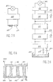
- FIGS. 1A to 1C A schematic description of devices corresponding is given in FIGS. 1A to 1C.
- FIG. 1A represents a machine for Stirling.
- a compressor 1 or pressure oscillator consists of a piston actuated mechanically by a crankshaft 2.
- the machine of Gifford and Mac Mahon illustrated in FIG. 1B, is characterized by a compressor gas 3 with low pressure inlet 4 and outlet 5 high pressure, permanent and connected to the machine refrigeration proper 10 by an inlet valve 6 and an outlet valve 7 respectively, which are open in turn to generate cycles of pressure required.
- the refrigerating machine 10 which is connected to these compressors 1 and 3 is the same in both cases. It consists of a tube 9 in which slides a displacer piston 11 which divides the contents of tube 9 into two variable volume chambers, interconnected by a bypass 12, on which a regenerator of heat 13 is installed.
- the room connected to compressor 1 or 3 is at temperature T2 (corresponding to the hot spring), and the other room is at temperature T3 of the cold source.
- the piston displacer 11 passes the compressed gas from the chamber at temperature T2, to the room at temperature T3, by exchanging its heat with the regenerator of heat 13 in response to pressure rises in the compressor.
- Gas expansion is produced when he mainly occupies the room at the temperature T3, then the gas is heated by crossing the heat regenerator 13 to the chamber temperature T2 before undergoing a new cycle.
- the heat regenerator 13 has the property of return to the gas flowing in one direction the heat that it took previously from the gas flowing in the direction reverse.
- the room at temperature T2 communicates with the compressor 3 via input 4 and output 5; in the realizations of FIG. 1A, the connection of the compressor 1 at the compressor chamber at temperature T2 east produced by a single pressure test pipe 15.
- the machines thus alternative are the seat of two periodic waves in the volume of trigger 15, one of pressure and the other of flow. he is possible to control the phase shift of these two waves by mechanical means which control the movements of the compressor piston 1 or of the valves 6 and 7, usually at room temperature, and the piston displacer 11 which can, for applications in cryogenics, having to operate at very low temperatures. We then actually arrive at the sought-after situation where maximum relaxation, i.e. maximum heat absorption, is simultaneous at the maximum gas flow in the cold source T3.
- maximum relaxation i.e. maximum heat absorption
- Figure 1C illustrates a tube machine pulsation. It includes a pressure oscillator 16, symbolized by a mechanical compressor, a regenerator heat 17 connected to the compressor 16 by a pressure tap 18 and a pulsation tube 19 which connects to the end of the heat regenerator 17 opposite to the pressure oscillator 16.
- the pressure tube pulse 19 is closed at the opposite end to the heat regenerator 17.
- the pulsation tube 19 is throttled near the heat regenerator 17, where the cold source SF is located, while the hot source SC is located at the opposite end of the pulsation 19, at the end of an enlarged portion and by cylindrical example of it.
- the gas column is maintained oscillations, and the dimensions and the shape of the various elements of the device allow to choose the operating frequency to obtain the phase shift of the flow waves and pressure which effectively extracts from the heat at the cold source, to transfer it to the hot spring.
- the Brayton cycle ( Figure 2A) can operate with nitrogen if the desired cold source 25 is at a temperature above 80 Kelvin. For lower temperatures, the cycle gas will generally helium.
- Claude's cycle in Figure 2A corresponds rather than a helium cycle, whose cold source 26 is a liquid helium bath.
- Relaxation without work or enthalpy constant does not absorb heat, but it is generally used in the immediate vicinity of the fluid saturation curve to achieve the phase change by expansion of the gas which is partially liquefied.
- the trigger with phase change is at proscribe to avoid mechanical destruction, either the turbine unbalanced by droplets, or piston subjected to the "blows" of the liquid which risks being there accumulate.
- the expansion turbines must rotate at high speeds, several dozen or more hundreds of thousands of revolutions per minute, and are generally supported by non-contact bearings, most often gas.
- the piston regulators are, a priori, better suitable as turbines for processing flows reduced, but their reliability is strongly conditioned by achieving friction sealing between piston and cylinder, and by the existence of valves cold with associated control mechanisms.
- the object of the invention relates to a solution original for making machines fluid cooling by expansion, in particular cryogenic (either isentropic or, if necessary, isothermal) better suited than turbines and machines piston to treat low flows with good efficiency, and good reliability, while being insensitive to the presence of liquid or fluid in double phase.
- cryogenic either isentropic or, if necessary, isothermal
- This device reduces the temperature fluid thanks to the expansion carried out in the relaxation compartment. There is therefore cooling of the fluid as soon as it leaves this compartment.
- the invention implements parts in movement without contact and without recourse to valves.
- This device is compatible with miniaturization to handle low flow rates.
- it can accept, without any problem, the formation of fluid two-phase during expansion.
- he may have at least one circuit in one of the spirals heat exchange allowing to tend towards isothermal conditions.
- means may be provided for control the speed of rotation of the moving spiral during its movement.
- the movable spiral can be linked to a part around which an eccentric sleeve is in rotation, a part linked to the eccentric sleeve able to support the rotor of an electric brake.
- This socket can be done with, on at least one of its two faces, a bearing contactless, magnetic or gas type.
- a means of controlling the axial play between the two spirals can be provided.
- Spirals can be, for example, Archimedes' spirals or defined by a succession of arcs of a circle.
- a fluid expansion system may include at least two trigger stages, each with a device according to one of the forms described above.
- a common tree can possibly allow a movement in phase of the moving spirals of the different trigger devices.
- a cryogenic expansion machine can therefore include a compressor, an exchanger and a device or an expansion system as described above.
- the principle of the invention is based on the use of a relaxation compartment comprising, as illustrated in FIGS. 3A to 3D and 4A, a first fixed spiral 28 and a second spiral 30 arranged mobile inside the first.
- Each spiral rests or is linked to a bottom flat 32, 34.
- the gas to be expanded is introduced through a tube 36.
- An exhaust may be provided. So, reduced clearances 40, 42, provided between the game upper partitions 28, 30 of the spirals and the flat bottoms 32, 34 allow the fluid to escape the outside of the movable spiral, then of the spiral fixed (arrow referenced 44 in Figure 4).
- Gas can only flow by increasing by volume (expansion) and by exerting a force on the wall mobile 30 (work), subjected to a movement of circular translation. Because of this movement, each point of the spiral 30 describes a circle, the part mobile permanently remaining parallel to itself.
- Figures 3A to 3D illustrate the process gas expansion in different stages, by which we can follow the evolution of a fraction of the gas, quarter turn to quarter turn. This gas passes by the continuously increasing volumes 46, 48, 50, 52, then finally 54, before exhaust.
- the volume of gas during expansion is at each moment limited by a partition of the spiral fixed and a partition of the movable spiral, which become tangent every 180 degrees, following their developed.
- the circular translation movement returns to drag the tangency points along the fixed spiral profile, allowing gas considered to move from the center to the outside of the spiral increasing in volume.
- FIG. 3E An example of realization with several spirals is illustrated in Figure 3E.
- Two fixed spirals 27 and 29 are arranged symmetrical, at 180 ° with respect to an axis of symmetry ⁇ .
- Two movable spirals 31 and 33 alternately become tangent on a face with the spiral 27 and on the other face with the spiral 29.
- the thicknesses of the partitions of the spirals can be chosen constant or variable for optimize their mechanical strength and footprint.
- the materials that can be used will satisfy preferably on condition that the two pieces (fixed and mobile) are compatible, from the point of view of their dilation, so that the reduced clearances are obtained at nominal operating conditions at low temperature.
- materials with low expansion such as fiber composites carbon, or metal alloys (like Invar).
- the copper or aluminum will be more favorable.
- materials with low density such as titanium or light alloys, strong enough to limit forces of inertia and the associated deformations.
- Plastic materials can also be used. They can come in massive form. They can also be locally reported (in the form of superficial segments or deposits), either for limit the effects of possible friction, either to obtain, by progressive wear, a running-in effect causing the pieces to adapt their shape to one the other. We will preferably try to reach the best compromise between poor contact and low leakage.
- the device flow can be adjusted by adjustment of its rotation speed.
- means for adjusting the speed of rotation can be provided. Examples will be given later.
- a device according to the invention can work at slow speed. For a fixed flow, a slow speed will bring more room usage bulky, therefore less sensitive to miniaturization to handle low flow rates.
- a decisive advantage of the invention results his ability to accept without any contraindication the formation, by relaxation, of fluid two-phase, whose liquid phase can possibly be evacuated to the exhaust without difficulty.
- FIGS. 4B and 4C Variants of the device of FIG. 4A are given in FIGS. 4B and 4C.
- a coil cold source 35 is fixed against the flat bottom 34 of the fixed spiral.
- a cold source 37 is integrated into the walls of the fixed spiral: a fluid can therefore circulate in these walls.
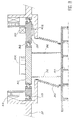
- FIG. 5 shows a cryogenic expansion valve whose fixed parts are supported by a structure 50 which carries two shafts 52, 63 to eccentric.
- the shaft 52 centered on the bearings 53 comprises an electric brake composed of a rotor 54 and a stator 55 to control the speed of rotation and extract the trigger work toward a adaptable load receiver 56.
- the shaft 52 is provided with two eccentric axes 57 and 58 which allow, through bearings 59 and 60 and an arm 62, a link mechanical with a movable plate 61.
- the arm 62 allowing a very stable and precise positioning.
- the mass of this arm can, moreover, be chosen for bring the center of gravity of the mobile assembly to desired level.
- the movable plate 61 is linked by the second eccentric shaft 63 mounted on ball bearings 64 and 65.
- the movement of this tree 63 is in phase with that of shaft 52, so that the movement of the plate 61 is a circular translation, without rotation.
- All the mechanical parts described above operate at room temperature in a housing 66 and a plate 67, which contain the fluid cycle 68.
- the latter can be, for example, helium at the exhaust pressure of the regulator, close to atmospheric pressure.
- Compressed gas 69 does a job by putting in movement the movable spiral 70 and the plate 61, both attached to at least one connecting element 71.
- the plate and fixed spiral 72, carried by a tube 73, are protected from external heat by a enclosure 74, which also allows vacuuming volume 75 by conventional means, not represented.
- the connecting elements 71 and the tube 73 have one hot end and one cold end. They are preferably sized to be mechanically rigid, while causing thermal leakage minimum to the gas circuit to be expanded.
- An auxiliary cooling circuit 76 for example supplied with liquid nitrogen around 80 K, allows reduce thermal leaks to trays 70 and 72.
- a helium liquefier with cycle of Claude such as that illustrated in FIG. 2B of the regulators of the type of that of FIG. 5 can be used with gas 69 and trays 70 and 72 working, on the first floor, around 50 to 60 Kelvin or, on the second floor, around 15 to 20 Kelvin.
- auxiliary circuit 76 will be preferably supplied by the previous stages at 50 K or 20 K.
- the movable spiral Under the effect of gas expansion 69 in the spiral compartment 70, 72, the movable spiral is driven in motion. The latter is transmitted by the connecting elements 71, to the plate 61.
- the trees eccentric 52, 63 in phase, block the own rotation component of the movement of the moving spiral. There remains the translational movement rotary of the latter, therefore of the plate 61 and the arm 62. Thanks to the eccentric axes 57, 58, the shaft 52 is rotated.
- the electric brake (stator 55 and rotor 54) makes it possible to control the speed of this rotation, therefore of the rotation of axes 57, 58 and therefore the speed of the rotary translational movement of the movable spiral 70.
- deformable elements such that a network of fibers or springs, one end of each fiber or spring being fixed to the movable spiral or at its flat bottom, while the other end is linked to the fixed part of the device.
- FIG. 6 A solution, implementing an element deformable, is illustrated in figure 6.
- the spiral mobile 77 is linked by connecting elements 78 to a movable plate 79 whose own rotation is blocked by a bellows 83.
- the latter is fixed, at its part lower, to plate 79, and at its upper part, to a fixed part 84 of the device.
- the bellows allows besides separating the atmosphere from part 86 of the enclosure, where lubricant vapors can exist, from part 87 of the gas enclosure high purity cycle.
- a shaft 80 with eccentric 85 fixes the circular translation stroke of the plate 79.
- This shaft 80 is rotated about its axis 88, fixed relative to the device.
- Axis 85 is rotating around the fixed axis 88.
- the shaft 80 can support also the rotor 81 of an electric brake, the stator is designated by reference 82.
- the device is, moreover, identical or similar to that described above in conjunction with Figure 5.
- Another solution implements means magnetic, exerting forces such as translation can take place by prohibiting the rotation.
- the moving part 88 or rather the flat bottom, or from above, the movable spiral is integral with a bar 89, either ferromagnetic or magnetized permed. Both are placed in the field magnetic of an external dipole 90 whose lines of Parallel fields set the orientation of the room.
- the moving part 88 and its bar 89 are represented in three different positions. These parts can be linked to a tray such as the plate 79 of FIG. 6, the latter being itself guided by a single eccentric, as described above in conjunction with this same figure 6.
- Fixed base 91 supports the brake stator 92 and the hot end of a bellows 93. The latter is intended for blocking the rotation of the moving spiral 94.
- the mobile part is made up of the plate central 95 connected to the movable spiral 94 by the connecting elements 96.
- An eccentric sleeve 97 free to rotate, is centered in the base 91 by the bearing 99 and supports the central plate 95 by means of the bearing 98.
- Dynamic balancing is obtained, on the one hand by a wedge 100 which allows to bring in the plane of bearings 98 and 99 the center of gravity of the assembly mobile 94, 96, 95, 100 and, on the other hand, by shims 101 and 102, which allow you to balance all inertias applied horizontally inside the bearing 99.
- cryogenic bearings without contact for example magnetic bearings or bearings with gas
- This solution has the advantage of greater mechanical rigidity to ensure better control of the respective position of fixed and mobile spirals intended for implementation of the invention.
- FIG. 9 shows a helium regulator at 7 K and approximately 15 bars which, for trigger, will go out of the spiral towards 4.5 K, under 1 bar, in double phase, with a high proportion of liquid.
- the gas to be expanded enters via line 111 to 7 Kelvin, he provides his work between the fixed spiral 112 and the moving spiral 113, before going out under form of liquid-vapor mixture via line 134.
- the moving equipment activated by the spiral 113, is connected by the connecting elements 115 to the plate 116 which rotates the eccentric sleeve 117, maintained in an axial position by the link 118 at ball bearing 119 located in the hot part, at 300 K, which is braked and speed controlled by the electric brake 120.
- the plate 116 is blocked in rotation by the bellows 121, itself fixed to the hot casing 122.
- the rotation of the socket 117 allows maintain, on both sides, two gas bearings 123 and 124 hydrodynamics, which provide movement without contact inside cryostat 125.
- This cryostat is protected from parasitic heat inputs by auxiliary cooling circuits 126, which hold the plate 116 of the socket 117, and the bearings 123 and 124 as well as a heat shield 127, around 20 Kelvin and via circuit 128, supplied to 80 K in liquid nitrogen, which is connected to screen 129.
- the axial play between the two spirals 112 and 113 is preferably rigorously controlled to stay close to a few hundredths of a millimeter.
- This clearance measured by a cold position sensor 131, is controlled by a regulator 132 which acts on the electroaiman 133, by controlled attraction of a ferromagnetic plate 134.
- a regulator according to one of the modes of realization described above can be used for perform a Brayton cycle, as described in the introduction to this application, in conjunction with Figure 2A.
- the invention is not limited to the realization single stage regulators using only one pair of spirals, one being fixed and the other mobile.
- the same mechanical crew and the same suspension set can be used for the operation of several regulators.
- the same mechanical equipment can be used to operate a three-stage regulator shown in Figure 10, where we voluntarily combined in combination several of the variants described previously.
- the second floor works between 15 bars, 25 Kelvin (at point 143) and 1.2 bar, 15 Kelvin (at point point 144).
- the third stage receives (in 145) gas under 15 bars at 7 Kelvin, which comes out (in 146) at 4.4 K in liquid-gas mixture at 1.3 bar.
- a possible variant to make relaxation on the third more insulated floor could be coat the tray of the fixed spiral 171 with a condenser 180 where could condense directly from liquid helium supplying the cold source.
- the three movable spirals 147, 148, 149 are linked to the same tree 150, the sections of which are decreasing with the temperature level.
- the shaft 150 is integral with a plate 151, at room temperature, and a tray 152, at temperature equal to around 30 Kelvin.
- the plate 151 rotates the ring offset 153 mounted on ball bearings 154 and 155. This ring is speed controlled by the brake 156.
- the eccentric ring 157 is held in position by a vertical magnetic stop 158. It is centered radially by two gas bearings hydrodynamics 159 and 160 which could equally be replaced by magnetic bearings, i.e. permanent magnets, either superconductive, of a nature to be defined according to the temperature level.
- the gas circuits are separated from each other others by bellows 176 and 177.
- Another bellows 178 separates the cryogenic circuit from the casing 179 which can either operate at a different pressure or contain lubricant vapors if the bearings 154 and 155 are greased.
- Bellows 176, 177 and 178 contribute, by elsewhere, to fix the mobile assembly in rotation integral with the plates 151 and 152 and the shaft 150 to control the desired movement of translation circular.
- the example was given of a three-way regulator floors to carry out a cycle of Claude. It is possible to make a regulator with a number different stages (either two, or a number N> 3). Of even, it is possible to use any combination of various embodiments set out above.
- the respective position of the fixed and mobile spirals must, preferably be able to be adjusted precisely, to limit the play both in the axial direction and in the radial direction.
- the means of adjustment used remain completely classic and have not been represented to avoid weighing down the illustrations.
Abstract
Description
L'invention concerne le domaine des machines de détente cryogénique.The invention relates to the field of cryogenic expansion.
Les cycles à gaz de réfrigération cryogénique peuvent être classés en deux catégories selon que le procédé considéré met en oeuvre, soit une circulation périodique en va et vient, soit une circulation permanente dans une direction définie du gaz.Cryogenic refrigeration gas cycles can be classified into two categories depending on whether the process considered implements either a circulation periodic back and forth, or circulation permanent in a defined direction of gas.
Dans les cycles à circulation alternée, le gaz échange de la chaleur avec un accumulateur thermique ou un régénérateur de chaleur qui retient la chaleur lorsque le gaz circule dans un sens, et la restitue lors du retour en sens inverse.In alternating circulation cycles, gas heat exchange with a thermal accumulator or a heat regenerator that retains heat when the gas flows in one direction, and restores it when returning in the opposite direction.
Les cycles à circulation alternative les plus connus sont les cycles de Stirling, de Gifford Mac Mahon, ou encore le cycle à tube de pulsation. Ce dernier est généralement réservé à la production de faibles puissances frigorifiques de l'ordre de la fraction de watt vers 4 Kelvin, de la dizaine de watts vers 15 Kelvin, et de la centaine de watts vers 80 Kelvin.The most reciprocating cycles known are the Stirling and Gifford cycles Mac Mahon, or the heartbeat cycle. This the latter is generally reserved for the production of low cooling capacities of the order of fraction of a watt around 4 Kelvin, from around ten watts around 15 Kelvin, and from the hundred watts towards 80 Kelvin.
Une description schématique de dispositifs correspondants est donnée sur les figure 1A à 1C.A schematic description of devices corresponding is given in FIGS. 1A to 1C.
La figure 1A représente une machine de
Stirling. Un compresseur 1 ou oscillateur de pression
est constitué d'un piston actionné mécaniquement par un
vilebrequin 2.FIG. 1A represents a machine for
Stirling. A
La machine de Gifford et Mac Mahon, illustrée
sur la figure 1B, se caractérise par un compresseur de
gaz 3 avec une entrée 4 à basse pression et une sortie
5 à haute pression, permanentes et reliées à la machine
frigorifique proprement dite 10 par un clapet d'entrée
6 et un clapet 7 de sortie respectivement, qui sont
ouverts à tour de rôle pour engendrer les cycles de
pression nécessaires.The machine of Gifford and Mac Mahon, illustrated
in FIG. 1B, is characterized by a compressor
gas 3 with low pressure inlet 4 and
La machine frigorifique 10, qui est reliée à
ces compresseurs 1 et 3 est la même dans les deux cas.
Elle consiste en un tube 9 dans lequel coulisse un
piston déplaceur 11 qui divise le contenu du tube 9 en
deux chambres à volume variable, reliées entre elles
par une dérivation 12, sur laquelle un régénérateur de
chaleur 13 est installé. La chambre reliée au
compresseur 1 ou 3 est à la température T2
(correspondant à la source chaude), et l'autre chambre
est à la température T3 de la source froide. Le piston
déplaceur 11 fait passer le gaz comprimé, de la chambre
à la température T2, vers la chambre à la température
T3, en échangeant sa chaleur avec le régénérateur de
chaleur 13 en réponse aux élévations de pression dans
le compresseur. La détente du gaz est produite
lorsqu'il occupe principalement la chambre à la
température T3, puis le gaz est réchauffé en traversant
le régénérateur de chaleur 13 vers la chambre à
température T2 avant de subir un nouveau cycle. Le
régénérateur de chaleur 13 a en effet la propriété de
restituer au gaz y circulant dans un sens la chaleur
qu'il a prise précédemment au gaz circulant en sens
inverse. Dans la réalisation de la figure 1B, la
chambre à la température T2 communique avec le
compresseur 3 par l'entrée 4 et la sortie 5 ; dans les
réalisations de la figure 1A, la liaison du compresseur
1 à la chambre du compresseur à la température T2 est
réalisée par un conduit unique de prise de pression 15.The refrigerating
A partir de l'illustration de la figure 1A, on
conçoit que les machines ainsi alternatives sont le
siège de deux ondes périodiques dans le volume de
détente 15, l'une de pression et l'autre de débit. Il
est possible de contrôler le déphasage de ces deux
ondes par des moyens mécaniques qui commandent les
mouvements du piston compresseur 1 ou des clapets 6 et
7, généralement à la température ambiante, et du piston
déplaceur 11 qui peut, pour les applications en
cryogénie, devoir fonctionner à de très basses
températures. On arrive alors effectivement à la
situation recherchée où la détente maximale, c'est-à-dire
l'absorption de chaleur maximale, est simultanée
au débit de gaz maximal dans la source froide T3.From the illustration in Figure 1A, we
conceives that the machines thus alternative are the
seat of two periodic waves in the volume of
La figure 1C illustre une machine à tube de
pulsation. Elle comprend un oscillateur de pression 16,
symbolisé par un compresseur mécanique, un régénérateur
de chaleur 17 relié au compresseur 16 par un conduit de
prise de pression 18 et un tube de pulsation 19 qui
s'embranche à l'extrémité du régénérateur de chaleur 17
opposée à l'oscillateur de pression 16. Le tube de
pulsation 19 est fermé à l'extrémité opposée au
régénérateur de chaleur 17. Par l'effet combiné des
différents volumes et étranglements, le déphasage
nécessaire à l'effet frigorifique des ondes de débit et
de pression est obtenu par des moyens totalement
statiques dans le tube de pulsation 19, qui est donc
libre ou dépourvu de tout objet mobile tel qu'un piston
déplaceur. Plus précisément, le tube de pulsation 19
est étranglé près du régénérateur de chaleur 17, où la
source froide SF est située, alors que la source chaude
SC est située à l'extrémité opposée du tube de
pulsation 19, au bout d'une portion élargie et par
exemple cylindrique de celui-ci. La colonne de gaz est
mise en oscillations entretenues, et les dimensions et
la forme des différents éléments de l'appareil
permettent de choisir la fréquence de fonctionnement
pour obtenir le déphasage des ondes de débit et de
pression qui permet d'extraire effectivement de la
chaleur à la source froide, pour la transférer vers la
source chaude.Figure 1C illustrates a tube machine
pulsation. It includes a
Les cycles à circulation continue sont, eux, mieux adaptés à la production de puissances élevées.Continuous circulation cycles are better suited to the production of high powers.
De telles machines, fonctionnant sur le principe du cycle de Brayton et du cycle de Claude sont respectivement illustrées sur les figures 2A et 2B. Elles sont constituées d'arrangements différents des trois composants principaux suivants :
- un
compresseur 20 recycle le gaz du niveau de basse pression (BP), habituellement voisin de la pression atmosphérique, jusqu'au niveau de haute pression, généralement compris entre 15 et 30 bars environ, - un ou des échangeurs de
chaleur 22 à contre-courant assurent le prérefroidissement du gaz comprimé par échange avec le gaz à basse pression, - une ou des machines de
détente 23 sont la ou les véritables sources de production frigorifique. On utilise, soit desmachines 23 dans lesquelles le gaz fournit un travail mécanique, soit de simples étranglements ou vannes dedétente 24 où le gaz subit une perte de charge.
- a
compressor 20 recycles the gas from the low pressure level (BP), usually close to atmospheric pressure, to the high pressure level, generally between around 15 and 30 bars, - one or more
counter-current heat exchangers 22 pre-cool the compressed gas by exchange with the gas at low pressure, - one or
more expansion machines 23 are the true source (s) of refrigeration production. We use eithermachines 23 in which the gas provides mechanical work, or simple throttles orexpansion valves 24 where the gas undergoes a pressure drop.
Le cycle de Brayton (figure 2A) peut
fonctionner avec de l'azote si la source froide désirée
25 est à une température supérieure à 80 Kelvin. Pour
les températures plus basses, le gaz de cycle sera
généralement l'hélium.The Brayton cycle (Figure 2A) can
operate with nitrogen if the desired
Le cycle de Claude de la figure 2A correspond
plutôt à un cycle à hélium, dont la source froide 26
est un bain d'hélium liquide.Claude's cycle in Figure 2A corresponds
rather than a helium cycle, whose
Les machines de détente susceptibles de
produire du travail mettent en application le premier
principe de la thermodynamique selon lequel la somme
des quantités de chaleur Q et de travail W mis en jeu
dans un cycle de transformations réversibles est
nulle :
Une détente avec travail permettra donc toujours d'absorber de la chaleur, mais elle nécessite l'utilisation de machines dont les pièces froides sont en mouvement.Relaxation with work will therefore allow still absorb heat but it requires the use of machines with cold parts moving.
Une détente sans travail ou à enthalpie constante n'absorbe pas de chaleur, mais elle est généralement utilisée à proximité immédiate de la courbe de saturation du fluide pour réaliser le changement de phase par détente du gaz qui se trouve partiellement liquéfié.Relaxation without work or enthalpy constant does not absorb heat, but it is generally used in the immediate vicinity of the fluid saturation curve to achieve the phase change by expansion of the gas which is partially liquefied.
La détente avec travail est effectuée, soit dans des turbines quand le débit est suffisant, soit dans des machines à piston un peu mieux adaptées aux faibles débits.Relaxation with work is performed, i.e. in turbines when the flow is sufficient, i.e. in piston machines a little better suited to low flow rates.
Dans les deux cas, le gaz en cours de détente ne peut pratiquement pas échanger de chaleur avec la source froide et la détente obtenue est dite adiabatique ou isentropique.In both cases, the gas being released practically cannot exchange heat with the cold source and the resulting relaxation is said adiabatic or isentropic.
Pour certaines application, il pourrait être préférable d'obtenir les conditions d'une détente isotherme permettant d'extraire plus de chaleur à condition d'assurer un échange de chaleur permanent avec un faible écart de température entre la source froide et le gaz en cours de détente.For some applications, it could be better to obtain the conditions for a relaxation insulated to extract more heat from condition to ensure a permanent heat exchange with a small temperature difference between the source cold and gas being released.
Tant pour les turbines que pour les machines à piston, la détente avec changement de phase est à proscrire pour éviter la destruction mécanique, soit de la turbine déséquilibrée par des gouttelettes, soit du piston soumis aux "coups" du liquide qui risque de s'y accumuler.Both for turbines and machines piston, the trigger with phase change is at proscribe to avoid mechanical destruction, either the turbine unbalanced by droplets, or piston subjected to the "blows" of the liquid which risks being there accumulate.
Même en limitant leur utilisation hors de la présence de liquide grâce à des températures ou des pressions suffisamment élevées, les machines de détentes couramment utilisées induisent de nombreuses difficultés de conception ou d'utilisation.Even by limiting their use outside the presence of liquid due to temperatures or sufficiently high pressures, the commonly used triggers induce many design or use difficulties.
Les turbines de détente doivent tourner à des vitesses élevées, de plusieurs dizaines ou plusieurs centaines de milliers de tours par minute, et sont généralement supportées par des paliers sans contact, le plus souvent à gaz.The expansion turbines must rotate at high speeds, several dozen or more hundreds of thousands of revolutions per minute, and are generally supported by non-contact bearings, most often gas.
Pour traiter de faibles débits, les turbines sont mal adaptées à la miniaturisation.To handle low flows, turbines are ill-suited to miniaturization.
En effet, quand le diamètre diminue jusque vers des tailles centimétriques, le jeu entre les parties mobile et fixe de la turbine prend une importance relative croissante, et le débit de fuite détendu sans travail fait chuter l'efficacité. Quand les buses d'injection où le gaz circule à vitesse sonique doivent être réduites à des diamètres du dixième de millimètre, les conditions d'écoulement deviennent rapidement perturbées et sources d'irréversibilités, ou simplement sujettes aux impuretés.Indeed, when the diameter decreases to centimeter sizes, the game between the parts mobile and fixed turbine takes on importance increasing relative, and the leakage rate relaxed without work lowers efficiency. When the nozzles injection where the gas flows at sonic speed must be reduced to diameters of one tenth of a millimeter, flow conditions quickly become disturbed and sources of irreversibility, or simply subject to impurities.
Les détendeurs à piston sont, a priori, mieux adaptés que les turbines pour traiter des débits réduits, mais leur fiabilité est fortement conditionnée par la réalisation de l'étanchéité frottante entre piston et cylindre, et par l'existence de clapets froids avec les mécanismes de commande associés.The piston regulators are, a priori, better suitable as turbines for processing flows reduced, but their reliability is strongly conditioned by achieving friction sealing between piston and cylinder, and by the existence of valves cold with associated control mechanisms.
L'objet de l'invention concerne une solution originale permettant de réaliser des machines de refroidissement de fluide par détente, en particulier cryogénique (soit isentropique, soit, si nécessaire, isotherme) mieux adaptées que les turbines et machines à piston pour traiter de faibles débits avec une bonne efficacité, et une bonne fiabilité, tout en étant insensible à la présence de liquide ou de fluide en double phase.The object of the invention relates to a solution original for making machines fluid cooling by expansion, in particular cryogenic (either isentropic or, if necessary, isothermal) better suited than turbines and machines piston to treat low flows with good efficiency, and good reliability, while being insensitive to the presence of liquid or fluid in double phase.
L'invention a pour objet un dispositif d'abaissement de température d'un fluide par détente du fluide, à l'état gazeux ou liquide ou en double phase, caractérisé en ce qu'il comporte un compartiment de détente comprenant :
- une première spirale,
- une seconde spirale disposée à l'intérieur de cette première spirale,
- des moyens pour permettre un mouvement de translation circulaire, sans rotation propre, de la seconde spirale à l'intérieur de la première, lors de la détente d'un fluide, et
- des moyens pour contrôler la vitesse de rotation de la spirale mobile lors de son mouvement.
- a first spiral,
- a second spiral placed inside this first spiral,
- means for allowing a circular translational movement, without proper rotation, of the second spiral inside the first, during the expansion of a fluid, and
- means for controlling the speed of rotation of the movable spiral during its movement.
Ce dispositif permet de diminuer la température du fluide grâce à la détente réalisée dans le compartiment de détente. Il y a donc refroidissement du fluide dès sa sortie de ce compartiment.This device reduces the temperature fluid thanks to the expansion carried out in the relaxation compartment. There is therefore cooling of the fluid as soon as it leaves this compartment.
L'invention met en oeuvre des pièces en mouvement sans contact et sans recours à des clapets. Ce dispositif est compatible avec une miniaturisation pour traiter de faibles débits. De plus, il peut accepter, sans aucun problème, la formation de fluide diphasique au cours de la détente. Il peut, en outre, comporter dans une des spirales au moins un circuit d'échange de chaleur permettant de tendre vers des conditions isothermes.The invention implements parts in movement without contact and without recourse to valves. This device is compatible with miniaturization to handle low flow rates. In addition, it can accept, without any problem, the formation of fluid two-phase during expansion. In addition, he may have at least one circuit in one of the spirals heat exchange allowing to tend towards isothermal conditions.
Les moyens permettant le mouvement de translation circulaire, sans rotation propre, peuvent prendre diverses formes. Ils peuvent par exemple comporter :
- deux arbres excentrés, chacun étant lié à la spirale mobile par une extrémité en rotation autour d'un axe fixe par rapport au dispositif,
- ou au moins une pièce déformable liée par une de ses extrémités à une partie fixe du dispositif et dont l'autre extrémité est liée à la spirale mobile,
- ou des moyens magnétiques exerçant sur la spirale mobile ou sur une partie fixe par rapport à la spirale mobile, des forces telles que la translation puisse avoir lieu en interdisant toute rotation.
- two eccentric shafts, each connected to the movable spiral by one end in rotation about an axis fixed relative to the device,
- or at least one deformable part linked by one of its ends to a fixed part of the device and the other end of which is linked to the movable spiral,
- or magnetic means exerting on the movable spiral or on a fixed part with respect to the movable spiral, forces such that translation can take place by preventing any rotation.
En outre, des moyens peuvent être prévus pour contrôler la vitesse de rotation de la spirale mobile lors de son mouvement.In addition, means may be provided for control the speed of rotation of the moving spiral during its movement.
Ainsi, dans le cas d'un mouvement avec deux excentriques, l'un d'eux peut porter le rotor d'un frein électrique, le stator étant fixe par rapport au dispositif.So in the case of a movement with two eccentric, one of them can carry the rotor of a electric brake, the stator being fixed relative to the device.
Dans le cas d'un mouvement avec pièces déformables, la spirale mobile peut être liée à une pièce autour de laquelle une douille excentrique est en rotation, une pièce liée à la douille excentrique pouvant supporter le rotor d'un frein électrique.In the case of a movement with coins deformable, the movable spiral can be linked to a part around which an eccentric sleeve is in rotation, a part linked to the eccentric sleeve able to support the rotor of an electric brake.
La rotation de cette douille peut se faire avec, sur au moins une de ses deux faces, un palier sans contact, du type magnétique ou à gaz.The rotation of this socket can be done with, on at least one of its two faces, a bearing contactless, magnetic or gas type.
Un moyen de contrôle du jeu axial entre les deux spirales peut être prévu. Les spirales peuvent être, par exemple, des spirales d'Archimède ou définies par une succession d'arcs de cercle.A means of controlling the axial play between the two spirals can be provided. Spirals can be, for example, Archimedes' spirals or defined by a succession of arcs of a circle.
Un système de détente de fluide peut comporter au moins deux étages de détente, chacun comportant un dispositif selon l'une des formes décrites ci-dessus. Un arbre commun peut éventuellement permettre un mouvement en phase des spirales mobiles des différents dispositifs de détente. A fluid expansion system may include at least two trigger stages, each with a device according to one of the forms described above. A common tree can possibly allow a movement in phase of the moving spirals of the different trigger devices.
Une machine de détente cryogénique peut donc comporter un compresseur, un échangeur et un dispositif ou un système de détente tels que décrits ci-dessus.A cryogenic expansion machine can therefore include a compressor, an exchanger and a device or an expansion system as described above.
De toute façon, les caractéristiques et avantages de l'invention apparaítront mieux à la lumière de la description qui va suivre. Cette description porte sur les exemples de réalisation, donnés à titre explicatif et non limitatif, en se référant à des dessins annexés sur lesquels :
- la figure 1A à 1C illustrent respectivement des machines de Stirling, Gifford et à tube de pulsation,
- les figures 2A et 2B illustrent des machines de Brayton et de Claude,
- les figures 3A à 3D illustrent le principe de fonctionnement d'un compartiment de détente d'un dispositif selon l'invention,
- la figure 3E représente un mode de réalisation avec 4 spirales,
- les figures 4A à 4C représentent une vue en coupe d'un compartiment de détente d'un dispositif soit adiabatique soit isotherme selon l'invention,
- la figure 5 représente une première réalisation de l'invention,
- les figures 6 à 9 représentent d'autres réalisations de l'invention,
- la figure 10 représente un détendeur à trois étages, conforme à l'invention.
- FIGS. 1A to 1C respectively illustrate Stirling, Gifford and pulsation tube machines,
- FIGS. 2A and 2B illustrate machines of Brayton and Claude,
- FIGS. 3A to 3D illustrate the operating principle of an expansion compartment of a device according to the invention,
- FIG. 3E represents an embodiment with 4 spirals,
- FIGS. 4A to 4C represent a cross-section view of an expansion compartment of an either adiabatic or isothermal device according to the invention,
- FIG. 5 represents a first embodiment of the invention,
- FIGS. 6 to 9 represent other embodiments of the invention,
- Figure 10 shows a three-stage regulator according to the invention.
Le principe de l'invention repose sur
l'utilisation d'un compartiment de détente comportant,
comme illustré sur les figures 3A à 3D et 4A, une
première spirale fixe 28 et une seconde spirale 30
disposée mobile à l'intérieur de la première.The principle of the invention is based on
the use of a relaxation compartment comprising,
as illustrated in FIGS. 3A to 3D and 4A, a
first fixed
Chaque spirale repose ou est liée à un fond plat 32, 34.Each spiral rests or is linked to a bottom flat 32, 34.
Le gaz à détendre est introduit par un tube
d'admission 36. Un échappement peut être prévu. Ainsi,
des jeux réduits 40, 42, assurés entre la partie
supérieure des cloisons 28, 30 des spirales et les
fonds plats 32, 34 permettent au fluide de s'échapper à
l'extérieur de la spirale mobile, puis de la spirale
fixe (flèche référencée 44 sur la figure 4).The gas to be expanded is introduced through a
Le gaz ne peut circuler qu'en augmentant de volume (détente) et en exerçant une force sur la paroi mobile 30 (travail), soumise à un mouvement de translation circulaire. Du fait de ce mouvement, chaque point de la spirale 30 décrit un cercle, la partie mobile restant en permanence parallèle à elle-même.Gas can only flow by increasing by volume (expansion) and by exerting a force on the wall mobile 30 (work), subjected to a movement of circular translation. Because of this movement, each point of the spiral 30 describes a circle, the part mobile permanently remaining parallel to itself.
Les figures 3A à 3D illustrent le déroulement
de l'expansion du gaz en différentes étapes, par
lesquelles on peut suivre l'évolution d'une fraction du
gaz, de quart de tour en quart de tour. Ce gaz passe
par les volumes continuellement croissants 46, 48, 50,
52, puis enfin 54, avant échappement.Figures 3A to 3D illustrate the process
gas expansion in different stages, by
which we can follow the evolution of a fraction of the
gas, quarter turn to quarter turn. This gas passes
by the continuously increasing
Le volume du gaz en cours de détente est à chaque instant limité par une cloison de la spirale fixe et une cloison de la spirale mobile, qui deviennent tangentes tous les 180 degrés, en suivant leur développée.The volume of gas during expansion is at each moment limited by a partition of the spiral fixed and a partition of the movable spiral, which become tangent every 180 degrees, following their developed.
Ces points de tangence procurent une étanchéité
totale ou partielle selon que les pièces sont en
contact ou de préférence séparées par un jeu réduit 40,
42.These tangent points provide a seal
total or partial depending on whether the parts are in
contact or preferably separated by a reduced
Le mouvement de translation circulaire revient à faire glisser les points de tangence le long du profil de la spirale fixe, permettant ainsi au gaz considéré de se déplacer du centre vers l'extérieur de la spirale en augmentant de volume.The circular translation movement returns to drag the tangency points along the fixed spiral profile, allowing gas considered to move from the center to the outside of the spiral increasing in volume.
Un très large éventail est offert pour la réalisation des pièces en spirale concernées :
- les profils en spirale pourront être des spirales d'Archimède (le rayon R d'une telle spirale varie linéairement avec l'angle à partir d'un même centre (R=a)),
- les profils pourront être définis par une succession d'arcs de cercle, de centres différents et de rayons différents, soit par exemple à chaque demi-tour, soit encore à chaque quart de tour.
- the spiral profiles may be Archimedes' spirals (the radius R of such a spiral varies linearly with the angle from the same center (R = a)),
- the profiles may be defined by a succession of arcs of a circle, of different centers and of different radii, either for example at each half-turn, or again at each quarter-turn.
Selon les débits à traiter et les taux de détente à obtenir, on pourra optimiser la géométrie, soit en utilisant une spirale unique, soit plusieurs spirales imbriquées en nombre quelconque.According to the debits to be treated and the rates of relaxation to obtain, we can optimize the geometry, either using a single spiral or multiple nested spirals in any number.
Un exemple de réalisation à plusieurs spirales
est illustré sur la figure 3E. Deux spirales fixes 27
et 29 sont disposées symétriques, à 180° par rapport à
un axe de symétrie Δ. Deux spirales mobiles 31 et 33
deviennent tangentes alternativement sur une face avec
la spirale 27 et sur l'autre face avec la spirale 29.An example of realization with several spirals
is illustrated in Figure 3E. Two fixed
Les épaisseurs des cloisons des spirales pourront être choisies constantes ou variables pour optimiser leur résistance mécanique et leur encombrement.The thicknesses of the partitions of the spirals can be chosen constant or variable for optimize their mechanical strength and footprint.
Les matériaux pouvant être utilisés satisferont de préférence à la condition que les deux pièces (fixe et mobile) soient compatibles, du point de vue de leur dilatation, de telle sorte que les jeux réduits soient obtenus aux conditions nominales de fonctionnement à basse température. Pour réduire les déformations, la préférence sera donnée aux matériaux à faible dilatation, tels que les composites par exemple à fibre de carbone, ou les alliages métalliques (comme l'Invar). Pour tendre vers des conditions isothermes le cuivre ou l'aluminium seront plus favorables. Pour la partie mobile on pourra utiliser des matériaux à faible densité, comme le titane ou les alliages légers, suffisamment résistants pour limiter les forces d'inertie et les déformations associées.The materials that can be used will satisfy preferably on condition that the two pieces (fixed and mobile) are compatible, from the point of view of their dilation, so that the reduced clearances are obtained at nominal operating conditions at low temperature. To reduce deformation, the preference will be given to materials with low expansion, such as fiber composites carbon, or metal alloys (like Invar). To tend towards isothermal conditions the copper or aluminum will be more favorable. For the moving part we can use materials with low density, such as titanium or light alloys, strong enough to limit forces of inertia and the associated deformations.
Des matériaux plastiques peuvent également être utilisés. Ils peuvent se présenter sous forme massive. Ils peuvent aussi être localement rapportés (sous forme de segments ou de dépôts superficiels), soit pour limiter les effets de possibles frottements, soit pour obtenir, par usure progressive, un effet de rodage amenant les pièces à adapter leur forme l'une à l'autre. On cherchera, de préférence, à atteindre le meilleur compromis entre un faible contact et une faible fuite.Plastic materials can also be used. They can come in massive form. They can also be locally reported (in the form of superficial segments or deposits), either for limit the effects of possible friction, either to obtain, by progressive wear, a running-in effect causing the pieces to adapt their shape to one the other. We will preferably try to reach the best compromise between poor contact and low leakage.
Les avantages essentiels de l'invention résident dans la possibilité offerte de réaliser une détente, avec travail du gaz, en utilisant des pièces en mouvement sans contact, et sans recours à des clapets.The essential advantages of the invention reside in the possibility offered to carry out a trigger, with gas working, using coins in movement without contact, and without recourse to valves.
Le débit du dispositif peut être ajusté par réglage de sa vitesse de rotation. A cet effet, des moyens pour régler la vitesse de rotation peuvent être prévus. Des exemples en seront donnés plus loin.The device flow can be adjusted by adjustment of its rotation speed. To this end, means for adjusting the speed of rotation can be provided. Examples will be given later.
Un dispositif conforme à l'invention peut travailler à vitesse lente. Pour un débit fixé, une vitesse lente amènera l'utilisation de chambres plus volumineuses, donc moins sensibles à la miniaturisation pour traiter de faibles débits.A device according to the invention can work at slow speed. For a fixed flow, a slow speed will bring more room usage bulky, therefore less sensitive to miniaturization to handle low flow rates.
Un avantage déterminant de l'invention résulte de son aptitude à accepter sans aucune contre-indication la formation, par détente, de fluide diphasique, dont la phase liquide peut éventuellement être évacuée vers l'échappement sans difficulté. A decisive advantage of the invention results his ability to accept without any contraindication the formation, by relaxation, of fluid two-phase, whose liquid phase can possibly be evacuated to the exhaust without difficulty.
Des variantes du dispositif de la figure 4A
sont données sur les figures 4B et 4C. Sur la figure
4B, une source froide à serpentin 35 est fixée contre
le fond plat 34 de la spirale fixe. Sur la figure 4C,
une source froide 37 est intégrée dans les parois de la
spirale fixe : un fluide peut donc circuler dans ces
parois.Variants of the device of FIG. 4A
are given in FIGS. 4B and 4C. On the face
4B, a
La figure 5 représente un détendeur cryogénique
dont les parties fixes sont supportées par une
structure 50 qui porte deux arbres 52, 63 à
excentrique.Figure 5 shows a cryogenic expansion valve
whose fixed parts are supported by a
L'arbre 52 centré sur les roulement 53 comporte
un frein électrique composé d'un rotor 54 et d'un
stator 55 permettant de contrôler la vitesse de
rotation et d'extraire le travail de détente vers un
récepteur 56 de charge adaptable.The
L'arbre 52 est muni de deux axes excentrés 57
et 58 qui permettent, par l'intermédiaire des
roulements 59 et 60 et d'un bras 62, une liaison
mécanique avec un plateau mobile 61. Le bras 62
permettant un positionnement très stable et précis. La
masse de ce bras peut, par ailleurs, être choisie pour
amener le centre de gravité de l'ensemble mobile au
niveau désiré.The
Le plateau mobile 61 est lié par le deuxième
arbre excentré 63 monté sur les roulements à bille 64
et 65. Le mouvement de cet arbre 63 est en phase avec
celui de l'arbre 52, de sorte que le mouvement du
plateau 61 soit une translation circulaire, sans
rotation.The movable plate 61 is linked by the second
Toutes les parties mécaniques décrites ci-dessus
fonctionnent à la température ordinaire dans un
boítier 66 et une platine 67, qui contiennent le fluide
de cycle 68. Ce dernier peut être, par exemple, de
l'hélium à la pression d'échappement du détendeur,
voisine de la pression atmosphérique.All the mechanical parts described above
operate at room temperature in a
Le gaz comprimé 69 exerce un travail en mettant
en mouvement la spirale mobile 70 et le plateau 61,
fixés tous deux à au moins un élément de liaison 71. Le
plateau et la spirale fixe 72, portée par un tube 73,
sont protégés des apports de chaleur extérieurs par une
enceinte 74, qui permet également de mettre sous vide
le volume 75 par des moyens classiques, non
représentés.
Les éléments de liaison 71 et le tube 73 ont
une extrémité chaude et une extrémité froide. Ils sont
de préférence dimensionnés pour être mécaniquement
rigides, tout en occasionnant une fuite thermique
minimale vers le circuit de gaz à détendre.The connecting
Un circuit de refroidissement auxiliaire 76,
par exemple alimenté en azote liquide vers 80 K, permet
de réduire les fuites thermiques vers les plateaux 70
et 72.An
Dans un liquéfacteur d'hélium à cycle de
Claude, tel que celui illustré sur la figure 2B des
détendeurs du type de celui de la figure 5 peuvent être
utilisés avec du gaz 69 et les plateaux 70 et 72
travaillant, au premier étage, vers 50 à 60 Kelvin ou,
au deuxième étage, vers 15 à 20 Kelvin.In a helium liquefier with cycle of
Claude, such as that illustrated in FIG. 2B of the
regulators of the type of that of FIG. 5 can be
used with
Pour sa part le dernier étage de détente, où
s'opère la liquéfaction partielle, fonctionne vers 5 à
7 Kelvin et, dans ce cas, le circuit auxiliaire 76 sera
de préférence alimenté par les étages précédents à 50 K
ou 20 K.For its part, the top relaxation floor, where
partial liquefaction takes place, works around 5 a
7 Kelvin and, in this case,
Sous l'effet de la détente du gaz 69 dans le
compartiment à spirales 70, 72, la spirale mobile est
entraínée en mouvement. Ce dernier est transmis, par
les éléments de liaison 71, au plateau 61. Les arbres
excentrés 52, 63, en phase, permettent de bloquer la
composante de rotation propre du mouvement de la
spirale mobile. Il reste le mouvement de translation
rotative de cette dernière, donc du plateau 61 et du
bras 62. Grâce aux axes 57, 58 excentrés, l'arbre 52
est entraíné en rotation. Le frein électrique (stator
55 et rotor 54) permet de contrôler la vitesse de cette
rotation, donc de la rotation des axes 57, 58 et donc
la vitesse du mouvement de translation rotative de la
spirale mobile 70.Under the effect of
D'autres solutions peuvent être trouvées pour interdire la rotation de la spirale mobile. On peut recourir, par exemple, à des éléments déformables tels qu'un réseau de fibres ou de ressorts, une extrémité de chaque fibre ou ressort étant fixée à la spirale mobile ou à son fond plat, tandis que l'autre extrémité est liée à la partie fixe du dispositif.Other solutions can be found for prohibit the rotation of the movable spiral. We can use, for example, deformable elements such that a network of fibers or springs, one end of each fiber or spring being fixed to the movable spiral or at its flat bottom, while the other end is linked to the fixed part of the device.
Une solution, mettant en oeuvre un élément
déformable, est illustrée sur la figure 6. La spirale
mobile 77 est liée, par des éléments de liaison 78 à un
plateau mobile 79 dont la rotation propre est bloquée
par un soufflet 83. Ce dernier est fixé, à sa partie
inférieure, au plateau 79, et à sa partie supérieure, à
une partie fixe 84 du dispositif. Le soufflet permet en
outre de séparer l'atmosphère de la partie 86 de
l'enceinte, où des vapeurs de lubrifiant peuvent
exister, de la partie 87 de l'enceinte réservée au gaz
de cycle à haute pureté. Un arbre 80 à excentrique 85
fixe la course de translation circulaire du plateau 79.
Cet arbre 80 est en rotation autour de son axe 88, fixe
par rapport au dispositif. L'axe 85 est en rotation
autour de l'axe fixe 88. L'arbre 80 peut supporter
également le rotor 81 d'un frein électrique dont le
stator est désigné par la référence 82. Le dispositif
est, par ailleurs, identique ou similaire à celui
décrit ci-dessus en liaison avec la figure 5. A solution, implementing an element
deformable, is illustrated in figure 6. The spiral
mobile 77 is linked by connecting
Une autre solution met en oeuvre des moyens magnétiques, exerçant des forces telles que la translation puisse avoir lieu en interdisant la rotation.Another solution implements means magnetic, exerting forces such as translation can take place by prohibiting the rotation.
Le principe de cette solution est illustré sur
la figure 7. La pièce mobile 88 ou plutôt le fond plat,
ou de dessus, de la spirale mobile est solidaire d'un
barreau 89, soit ferromagnétique, soit à aimantation
permanente. Tous deux sont placés dans le champ
magnétique d'un dipôle extérieur 90 dont les lignes de
champ parallèles fixent l'orientation de la pièce.The principle of this solution is illustrated on
FIG. 7. The moving
La pièce mobile 88 et son barreau 89 sont
représentés dans trois positions différentes. Ces
parties peuvent être liées à un plateau tel que le
plateau 79 de la figure 6, ce dernier étant lui-même
guidé par un excentrique unique, ainsi que décrit ci-dessus
en liaison avec cette même figure 6.The moving
Une autre variante capable d'assurer la transmission mécanique du mouvement de translation circulaire sera utilisée de préférence pour sa plus grande compacité et la plus grande facilité d'équilibrage dynamique. Cette variante est illustrée sur la figure 8.Another variant capable of ensuring mechanical transmission of the translational movement circular will be used preferably for its more great compactness and ease dynamic balancing. This variant is illustrated in figure 8.
Le socle fixe 91 supporte le stator du frein
électrique 92 et l'extrémité chaude d'un soufflet 93.
Ce dernier est destiné au blocage en rotation de la
spirale mobile 94.Fixed
La partie mobile est composée du plateau
central 95 relié à la spirale mobile 94 par les
éléments de liaison 96.The mobile part is made up of the plate
central 95 connected to the
Une douille excentrique 97, libre en rotation,
est centrée dans le socle 91 par le roulement 99 et
supporte le plateau central 95 au moyen du roulement
98. An
La translation circulaire de la spirale mobile
94 est transformée en rotation de la douille 97 dont la
vitesse est contrôlée par le frein électrique 92.The circular translation of the moving
Un équilibrage dynamique est obtenu, d'une part
par une cale 100 qui permet d'amener dans le plan des
roulements 98 et 99 le centre de gravité de l'ensemble
mobile 94, 96, 95, 100 et, d'autre part, par des cales
101 et 102, qui permettent de balancer toutes les
inerties appliquées horizontalement à l'intérieur du
roulement 99.Dynamic balancing is obtained, on the one hand
by a
Toutes les solutions décrites précédemment utilisent différentes variantes mécaniques mais restent essentiellement conçues pour fonctionner à la température ordinaire.All the solutions described above use different mechanical variants but remain basically designed to operate at the ordinary temperature.
L'utilisation de paliers cryogéniques sans contact (par exemple paliers magnétiques ou paliers à gaz) peut aussi donner lieu à une deuxième famille de solutions. Cette solution présente l'avantage d'une plus grande rigidité mécanique pour permettre d'assurer un meilleur contrôle de la position respective des spirales fixes et mobiles destinées à la mise en oeuvre de l'invention.The use of cryogenic bearings without contact (for example magnetic bearings or bearings with gas) can also give rise to a second family of solutions. This solution has the advantage of greater mechanical rigidity to ensure better control of the respective position of fixed and mobile spirals intended for implementation of the invention.
Un exemple, illustré sur la figure 9, utilise en combinaison des paliers à gaz radiaux et une butée axiale magnétique. On aurait aussi bien pu utiliser l'inverse, ou toute autre combinaison imaginable entre ces deux technologies connues.An example, illustrated in Figure 9, uses in combination with radial gas bearings and a stop axial magnetic. We might as well have used the reverse, or any other combination imaginable between these two known technologies.
L'exemple de la figure 9 représente un détendeur d'hélium à 7 K et environ 15 bars qui, par détente, va sortir de la spirale vers 4,5 K, sous 1 bar, en double phase, avec une forte proportion de liquide.The example in Figure 9 shows a helium regulator at 7 K and approximately 15 bars which, for trigger, will go out of the spiral towards 4.5 K, under 1 bar, in double phase, with a high proportion of liquid.
La même solution pourrait, a fortiori, être utilisée pour la détente d'hélium à toute autre température comme par exemple 20 K ou 60 K, ou à toute autre pression.The same solution could, a fortiori, be used for the expansion of helium to any other temperature such as 20 K or 60 K, or at any other pressure.
La même solution pourrait, de même, être utilisée pour la détente de tout autre gaz comme par exemple l'hydrogène, le néon ou l'azote, aux niveaux adaptés de température et de pression.The same solution could, likewise, be used for the expansion of any other gas as by example hydrogen, neon or nitrogen, at the levels suitable for temperature and pressure.
Le gaz à détendre entre par la conduite 111 à
7 Kelvin, il fournit son travail entre la spirale fixe
112 et la spirale mobile 113, avant de sortir sous
forme de mélange liquide-vapeur par la conduite 134.The gas to be expanded enters via
L'équipage mobile, actionné par la spirale 113,
est reliée par les éléments de liaison 115 au plateau
116 qui met en rotation la douille excentrique 117,
maintenue en position axiale par la liaison 118 au
roulement à bille 119 situé dans la partie chaude, à
300 K, et qui est freiné et contrôlé en vitesse par le
frein électrique 120.The moving equipment, activated by the
Le plateau 116 est bloqué en rotation par le
soufflet 121, lui-même fixé au carter chaud 122.The
La rotation de la douille 117 permet
d'entretenir, sur ses deux faces, deux paliers à gaz
hydrodynamiques 123 et 124, qui assurent le mouvement
sans contact à l'intérieur du cryostat 125. Ce cryostat
est protégé des entrées de chaleur parasites par les
circuits de refroidissement auxiliaires 126, qui
maintiennent le plateau 116 de la douille 117, et les
paliers 123 et 124 ainsi qu'un écran thermique 127,
vers 20 Kelvin et par le circuit 128, alimenté vers
80 K en azote liquide, qui est relié à l'écran 129.The rotation of the
Toutes les parties froides sont installées dans
une enceinte à vide 130, dont les moyens de pompage ne
sont pas représentés.All cold parts are installed in
a
Le jeu axial entre les deux spirales 112 et 113
est de préférence contrôlé avec rigueur pour rester
voisin de quelques centièmes de millimètres. The axial play between the two
Ce jeu, mesuré par un capteur de position froid
131, est contrôlé par un régulateur 132 qui agit sur
l'électroaiman 133, par attraction contrôlée d'une
plaque ferromagnétique 134.This clearance, measured by a
Pour éviter d'avoir à générer des efforts trop
importants dans l'électroaimant 133, on peut soit
perforer la paroi du soufflet 121 pour le mettre en
équipression, soit contrôler la pression interne du
soufflet 121 à une valeur voisine de la pression de
détente du mélange obtenu dans la conduite de sortie
134.To avoid having to generate too much effort
important in the
Un détendeur selon l'un des modes de réalisation décrits ci-dessus peut être utilisé pour réaliser un cycle de Brayton, comme décrit dans l'introduction à la présente demande, en liaison avec la figure 2A.A regulator according to one of the modes of realization described above can be used for perform a Brayton cycle, as described in the introduction to this application, in conjunction with Figure 2A.
L'invention ne se limite pas à la réalisation de détendeurs monoétagés n'utilisant qu'une seule paire de spirales, l'une étant fixe et l'autre mobile.The invention is not limited to the realization single stage regulators using only one pair of spirals, one being fixed and the other mobile.
En particulier, elle peut être mise en oeuvre de telle sorte qu'un même équipage mécanique et un même jeu de suspension puissent servir au fonctionnement de plusieurs détendeurs. Par exemple, pour réaliser un réfrigérateur à cycle de Claude comme illustré sur la figure 2B, un même équipage mécanique peut être utilisé pour faire fonctionner un détendeur à trois étages représenté sur la figure 10, où on a volontairement réuni en combinaison plusieurs des variantes décrites précédemment.In particular, it can be implemented so that the same mechanical crew and the same suspension set can be used for the operation of several regulators. For example, to make a Claude cycle refrigerator as illustrated on the Figure 2B, the same mechanical equipment can be used to operate a three-stage regulator shown in Figure 10, where we voluntarily combined in combination several of the variants described previously.
Au premier étage, l'hélium entre sous 15 bars
et 80 Kelvin par la conduite 141, et il ressort détendu
à 1,1 bar et 50 Kelvin en 142.On the first floor, helium enters under 15 bars
and 80 Kelvin through
Le deuxième étage travaille entre 15 bars, 25 Kelvin (au point 143) et 1,2 bar, 15 Kelvin (au point 144). The second floor works between 15 bars, 25 Kelvin (at point 143) and 1.2 bar, 15 Kelvin (at point point 144).
Le troisième étage reçoit (en 145) du gaz sous 15 bars à 7 Kelvin, qui ressort (en 146) à 4,4 K en mélange liquide-gaz sous 1,3 bar.The third stage receives (in 145) gas under 15 bars at 7 Kelvin, which comes out (in 146) at 4.4 K in liquid-gas mixture at 1.3 bar.
Une variante possible pour rendre la détente
sur troisième étage plus isotherme pourrait être de
revêtir le plateau de la spirale fixe 171 d'un
condenseur 180 où pourrait se condenser directement de
l'hélium liquide alimentant la source froide.A possible variant to make relaxation
on the third more insulated floor could be
coat the tray of the fixed
Les trois spirales mobiles 147, 148, 149 sont
liées à un même arbre 150, dont les sections sont
décroissantes avec le niveau de température.The three
L'arbre 150 est solidaire d'un plateau 151, à
température ambiante, et d'un plateau 152, à
température égale à environ 30 Kelvin.The
Le plateau 151 actionne en rotation la bague
excentrée 153 montée sur les roulements à bille 154 et
155. Cette bague est contrôlée en vitesse par le frein
156.The
Au niveau du plateau froid 152, une autre
technologie est utilisée, qui est la mise en rotation
d'une bague excentrée 157. Elle pourrait elle aussi
être freinée mais, sur la figure 10, elle est
représentée libre.At the
La bague excentrée 157 est maintenue en
position par une butée verticale magnétique 158. Elle
est centrée radialement par deux paliers à gaz
hydrodynamiques 159 et 160 qui pourraient tout aussi
bien être remplacés par des paliers magnétiques, soit à
aimants permanents, soit à supraconducteurs, d'une
nature à définir selon le niveau de température.The
Les spirales fixes 171, 172 et 173 sont
solidaires d'un carter 174 qui sera isolé par une
enceinte à vide (dont on a seulement ébauché l'amorce
175 sans en représenter les moyens de pompage). Fixed spirals 171, 172 and 173 are
secured to a
Les circuits de gaz sont séparés les uns des
autres par des soufflets 176 et 177. Un autre soufflet
178 sépare le circuit cryogénique du carter 179 qui
peut, soit fonctionner à une pression différente, soit
contenir des vapeurs de lubrifiant si les roulements
154 et 155 sont graissés.The gas circuits are separated from each other
others by
Les soufflets 176, 177 et 178 contribuent, par
ailleurs, à fixer en rotation l'équipage mobile
solidaire des plateaux 151 et 152 et de l'arbre 150
pour contrôler le mouvement désiré de translation
circulaire.
L'exemple a été donné d'un détendeur à trois étages pour réaliser un cycle de Claude. Il est possible de réaliser un détendeur avec un nombre différent d'étages (soit deux, soit un nombre N>3). De même, il est possible d'utiliser toute combinaison des divers modes de réalisation exposés ci-dessus.The example was given of a three-way regulator floors to carry out a cycle of Claude. It is possible to make a regulator with a number different stages (either two, or a number N> 3). Of even, it is possible to use any combination of various embodiments set out above.
Dans tous les exemples décrits précédemment, la position respective des spirales fixes et mobiles doit, de préférence, pouvoir être ajustée précisément, pour limiter les jeux tant dans le sens axial que dans le sens radial. Les moyens de réglage utilisés restent tout à fait classiques et n'ont pas été représentés pour éviter d'alourdir les illustrations. On peut, par exemple, utiliser des cales d'épaisseur adaptée pour les réglages axiaux et prévoir des moyens de réglage de l'entraxe des arbres excentriques pour ajuster les courses. On peut aussi envisager des opérations de rodage en position afin d'éliminer d'éventuels défauts de surface ou de géométrie.In all the examples described above, the respective position of the fixed and mobile spirals must, preferably be able to be adjusted precisely, to limit the play both in the axial direction and in the radial direction. The means of adjustment used remain completely classic and have not been represented to avoid weighing down the illustrations. We can, by example, use shims of suitable thickness for axial adjustments and provide means for adjusting the distance between the eccentric shafts to adjust the races. We can also consider operations of running in position in order to eliminate possible faults surface or geometry.
Claims (29)
Applications Claiming Priority (3)
| Application Number | Priority Date | Filing Date | Title |
|---|---|---|---|
| FR9508608 | 1995-07-17 | ||
| FR9508608A FR2736999B1 (en) | 1995-07-17 | 1995-07-17 | CRYOGENIC TO SPIRAL RELAXATION MACHINE |
| EP96925790A EP0839258A1 (en) | 1995-07-17 | 1996-07-16 | Scroll decompression device for cryogenic temperatures |
Related Parent Applications (1)
| Application Number | Title | Priority Date | Filing Date |
|---|---|---|---|
| EP96925790A Division EP0839258A1 (en) | 1995-07-17 | 1996-07-16 | Scroll decompression device for cryogenic temperatures |
Publications (2)
| Publication Number | Publication Date |
|---|---|
| EP1251278A2 true EP1251278A2 (en) | 2002-10-23 |
| EP1251278A3 EP1251278A3 (en) | 2003-05-21 |
Family
ID=9481038
Family Applications (2)
| Application Number | Title | Priority Date | Filing Date |
|---|---|---|---|
| EP96925790A Withdrawn EP0839258A1 (en) | 1995-07-17 | 1996-07-16 | Scroll decompression device for cryogenic temperatures |
| EP02077846A Withdrawn EP1251278A3 (en) | 1995-07-17 | 1997-02-06 | Scroll decompression device for cryogenic temperatures |
Family Applications Before (1)
| Application Number | Title | Priority Date | Filing Date |
|---|---|---|---|
| EP96925790A Withdrawn EP0839258A1 (en) | 1995-07-17 | 1996-07-16 | Scroll decompression device for cryogenic temperatures |
Country Status (4)
| Country | Link |
|---|---|
| EP (2) | EP0839258A1 (en) |
| JP (1) | JPH11509597A (en) |
| FR (1) | FR2736999B1 (en) |
| WO (1) | WO1997004215A1 (en) |
Families Citing this family (4)
| Publication number | Priority date | Publication date | Assignee | Title |
|---|---|---|---|---|
| FR2764347B1 (en) * | 1997-06-05 | 1999-07-30 | Alsthom Cge Alcatel | SCROLL TYPE MACHINE |
| JP4618478B2 (en) * | 2001-08-01 | 2011-01-26 | 株式会社豊田自動織機 | Scroll compressor |
| RU2716780C1 (en) * | 2019-07-29 | 2020-03-16 | Юрий Иванович Духанин | Turboexpander |
| CN114033675A (en) * | 2021-11-25 | 2022-02-11 | 合肥圣三松冷热技术有限公司 | Three-stage scroll structure compressor |
Citations (8)
| Publication number | Priority date | Publication date | Assignee | Title |
|---|---|---|---|---|
| FR1596943A (en) * | 1967-12-18 | 1970-06-22 | ||
| US3817664A (en) * | 1972-12-11 | 1974-06-18 | J Bennett | Rotary fluid pump or motor with intermeshed spiral walls |
| DE3017045A1 (en) * | 1979-05-14 | 1980-11-27 | Aginfor Ag | Flowmeter with spiral rotor - has rotor supported in stator by pairs of magnets in end plates to eliminate friction of bearings |
| US4291547A (en) * | 1978-04-10 | 1981-09-29 | Hughes Aircraft Company | Screw compressor-expander cryogenic system |
| FR2532011A1 (en) * | 1982-08-20 | 1984-02-24 | Volkswagen Ag | Spiral compressor with orbiting spiral wall disc |
| JPS59110894A (en) * | 1982-12-15 | 1984-06-26 | Hitachi Ltd | Scroll type fluid machine |
| EP0122722A1 (en) * | 1983-03-15 | 1984-10-24 | Sanden Corporation | Axial sealing device for a scroll type fluid displacement apparatus |
| US5391065A (en) * | 1993-10-26 | 1995-02-21 | Ingersoll-Rand Company | Parallel adjustment assembly for a scroll compressor |
Family Cites Families (3)
| Publication number | Priority date | Publication date | Assignee | Title |
|---|---|---|---|---|
| US4472120A (en) * | 1982-07-15 | 1984-09-18 | Arthur D. Little, Inc. | Scroll type fluid displacement apparatus |
| GB2132276B (en) * | 1982-12-23 | 1986-10-01 | Copeland Corp | Scroll-type rotary fluid-machine |
| CH672351A5 (en) * | 1986-12-24 | 1989-11-15 | Bbc Brown Boveri & Cie |
-
1995
- 1995-07-17 FR FR9508608A patent/FR2736999B1/en not_active Expired - Fee Related
-
1996
- 1996-07-16 EP EP96925790A patent/EP0839258A1/en not_active Withdrawn
- 1996-07-16 WO PCT/FR1996/001102 patent/WO1997004215A1/en not_active Application Discontinuation
- 1996-07-16 JP JP9506349A patent/JPH11509597A/en not_active Ceased
-
1997
- 1997-02-06 EP EP02077846A patent/EP1251278A3/en not_active Withdrawn
Patent Citations (8)
| Publication number | Priority date | Publication date | Assignee | Title |
|---|---|---|---|---|
| FR1596943A (en) * | 1967-12-18 | 1970-06-22 | ||
| US3817664A (en) * | 1972-12-11 | 1974-06-18 | J Bennett | Rotary fluid pump or motor with intermeshed spiral walls |
| US4291547A (en) * | 1978-04-10 | 1981-09-29 | Hughes Aircraft Company | Screw compressor-expander cryogenic system |
| DE3017045A1 (en) * | 1979-05-14 | 1980-11-27 | Aginfor Ag | Flowmeter with spiral rotor - has rotor supported in stator by pairs of magnets in end plates to eliminate friction of bearings |
| FR2532011A1 (en) * | 1982-08-20 | 1984-02-24 | Volkswagen Ag | Spiral compressor with orbiting spiral wall disc |
| JPS59110894A (en) * | 1982-12-15 | 1984-06-26 | Hitachi Ltd | Scroll type fluid machine |
| EP0122722A1 (en) * | 1983-03-15 | 1984-10-24 | Sanden Corporation | Axial sealing device for a scroll type fluid displacement apparatus |
| US5391065A (en) * | 1993-10-26 | 1995-02-21 | Ingersoll-Rand Company | Parallel adjustment assembly for a scroll compressor |
Non-Patent Citations (1)
| Title |
|---|
| PATENT ABSTRACTS OF JAPAN vol. 8, no. 230 (M-333) [1667], 23 octobre 1984 (1984-10-23) & JP 59 110894 A (HITACHI), 26 juin 1984 (1984-06-26) * |
Also Published As
| Publication number | Publication date |
|---|---|
| FR2736999B1 (en) | 1997-08-22 |
| WO1997004215A1 (en) | 1997-02-06 |
| FR2736999A1 (en) | 1997-01-24 |
| JPH11509597A (en) | 1999-08-24 |
| EP1251278A3 (en) | 2003-05-21 |
| EP0839258A1 (en) | 1998-05-06 |
Similar Documents
| Publication | Publication Date | Title |
|---|---|---|
| US5987894A (en) | Temperature lowering apparatus using cryogenic expansion with the aid of spirals | |
| EP2831490B1 (en) | Tank filling device and method | |
| JPH0444202A (en) | Cryostat with liquefying refrigerating machine | |
| EP0614059B1 (en) | Cooler with a cold finger of pulse tube type | |
| EP0279739B1 (en) | Refrigerator, particularly one using a vuilleumier cycle, having pistons suspended by gas bearings | |
| EP3414498A1 (en) | Cryogenic refrigeration device | |
| EP4107450A1 (en) | Dilution refrigeration device and method | |
| CH664799A5 (en) | STIRLING FREE PISTON HEAT PUMP ASSEMBLY. | |
| Ross Jr | Refrigeration systems for achieving cryogenic temperatures | |
| EP1251278A2 (en) | Scroll decompression device for cryogenic temperatures | |
| Fast | Advances in cryogenic engineering | |
| Garg et al. | Effect of Porosity of the regenerator on the performance of a miniature Stirling cryocooler | |
| EP4010645A1 (en) | Semi-permeable membrane with pores resulting from volatile substance | |
| Radebaugh | Microscale heat transfer at low temperatures | |
| FR2914050A1 (en) | Low/very low temperature refrigerator e.g. dilution type refrigerator, for use in research laboratory, has exchanger in contact with helium of regenerator, and component system or copper part thermally coupled between exchanger and coolant | |
| WO2021023455A1 (en) | Refrigeration device and facility | |
| WO1997003327A1 (en) | Refrigerator or heat pump with a pulse tube operated by a pressure generator | |
| FR2742215A1 (en) | STIRLING COOLER WITH ROTARY STEERING | |
| Wagner | Refrigeration | |
| Hong et al. | Development of Stirling-type pulse tube cryocooler | |
| Belrzaeg et al. | Overview of the Cryogenic Refrigeration Systems | |
| Muley et al. | Development of a helium recondensing cryostat | |
| FR1465047A (en) | Cooling device | |
| WO2015121179A1 (en) | System for cooling a hot source | |
| Hiratsuka et al. | Development of orientation-free high power stirling-type pulse tube cryocooler |
Legal Events
| Date | Code | Title | Description |
|---|---|---|---|
| PUAI | Public reference made under article 153(3) epc to a published international application that has entered the european phase |
Free format text: ORIGINAL CODE: 0009012 |
|
| AC | Divisional application: reference to earlier application |
Ref document number: 839258 Country of ref document: EP |
|
| AK | Designated contracting states |
Kind code of ref document: A2 Designated state(s): DE GB IT |
|
| PUAL | Search report despatched |
Free format text: ORIGINAL CODE: 0009013 |
|
| AK | Designated contracting states |
Designated state(s): DE GB IT |
|
| RIC1 | Information provided on ipc code assigned before grant |
Ipc: 7F 01C 21/16 B Ipc: 7F 01C 17/00 B Ipc: 7F 01C 17/06 B Ipc: 7F 01C 1/02 A |
|
| 17P | Request for examination filed |
Effective date: 20031024 |
|
| AKX | Designation fees paid |
Designated state(s): DE GB |
|
| STAA | Information on the status of an ep patent application or granted ep patent |
Free format text: STATUS: THE APPLICATION IS DEEMED TO BE WITHDRAWN |
|
| 18D | Application deemed to be withdrawn |
Effective date: 20060404 |