EP1249557A2 - Verlegeprofilsystem für profilierte Platten - Google Patents
Verlegeprofilsystem für profilierte Platten Download PDFInfo
- Publication number
- EP1249557A2 EP1249557A2 EP02005467A EP02005467A EP1249557A2 EP 1249557 A2 EP1249557 A2 EP 1249557A2 EP 02005467 A EP02005467 A EP 02005467A EP 02005467 A EP02005467 A EP 02005467A EP 1249557 A2 EP1249557 A2 EP 1249557A2
- Authority
- EP
- European Patent Office
- Prior art keywords
- profile
- elements
- laying
- frame elements
- profile system
- Prior art date
- Legal status (The legal status is an assumption and is not a legal conclusion. Google has not performed a legal analysis and makes no representation as to the accuracy of the status listed.)
- Withdrawn
Links
- 238000009434 installation Methods 0.000 claims description 9
- 239000004033 plastic Substances 0.000 abstract description 8
- 229920003023 plastic Polymers 0.000 abstract description 8
- 229910052751 metal Inorganic materials 0.000 abstract description 6
- 239000002184 metal Substances 0.000 abstract description 6
- 240000006829 Ficus sundaica Species 0.000 description 3
- 229910052782 aluminium Inorganic materials 0.000 description 2
- XAGFODPZIPBFFR-UHFFFAOYSA-N aluminium Chemical compound [Al] XAGFODPZIPBFFR-UHFFFAOYSA-N 0.000 description 2
- -1 polyethylene Polymers 0.000 description 2
- 229920001169 thermoplastic Polymers 0.000 description 2
- 239000004698 Polyethylene Substances 0.000 description 1
- 239000004743 Polypropylene Substances 0.000 description 1
- 239000004793 Polystyrene Substances 0.000 description 1
- 229920000122 acrylonitrile butadiene styrene Polymers 0.000 description 1
- 239000010426 asphalt Substances 0.000 description 1
- 230000015572 biosynthetic process Effects 0.000 description 1
- NTXGQCSETZTARF-UHFFFAOYSA-N buta-1,3-diene;prop-2-enenitrile Chemical compound C=CC=C.C=CC#N NTXGQCSETZTARF-UHFFFAOYSA-N 0.000 description 1
- 230000006866 deterioration Effects 0.000 description 1
- 238000005553 drilling Methods 0.000 description 1
- 229920001971 elastomer Polymers 0.000 description 1
- 238000001125 extrusion Methods 0.000 description 1
- 239000002657 fibrous material Substances 0.000 description 1
- 238000002347 injection Methods 0.000 description 1
- 239000007924 injection Substances 0.000 description 1
- 239000000463 material Substances 0.000 description 1
- 230000004048 modification Effects 0.000 description 1
- 238000012986 modification Methods 0.000 description 1
- 229920003229 poly(methyl methacrylate) Polymers 0.000 description 1
- 239000004417 polycarbonate Substances 0.000 description 1
- 229920000515 polycarbonate Polymers 0.000 description 1
- 229920000573 polyethylene Polymers 0.000 description 1
- 239000004926 polymethyl methacrylate Substances 0.000 description 1
- 229920001155 polypropylene Polymers 0.000 description 1
- 229920002223 polystyrene Polymers 0.000 description 1
- 229920000915 polyvinyl chloride Polymers 0.000 description 1
- 239000004800 polyvinyl chloride Substances 0.000 description 1
- 239000005060 rubber Substances 0.000 description 1
- 239000000243 solution Substances 0.000 description 1
- 229920003051 synthetic elastomer Polymers 0.000 description 1
- 239000005061 synthetic rubber Substances 0.000 description 1
- 239000004416 thermosoftening plastic Substances 0.000 description 1
Images




Classifications
-
- E—FIXED CONSTRUCTIONS
- E04—BUILDING
- E04D—ROOF COVERINGS; SKY-LIGHTS; GUTTERS; ROOF-WORKING TOOLS
- E04D3/00—Roof covering by making use of flat or curved slabs or stiff sheets
- E04D3/36—Connecting; Fastening
- E04D3/366—Connecting; Fastening by closing the space between the slabs or sheets by gutters, bulges, or bridging elements, e.g. strips
Definitions
- the invention relates to a laying profile system for profiled plate elements on an existing substructure
- EP 0 058 768 describes connecting profile rungs for corrugated sheets, with their Help the panels can be laid without overlaps.
- the Connection profile rung bridges two plates in each Vertex of the waveform. In this way an intrusion of protection avoided in overlap rooms. Otherwise the plates have to be conventional be screwed onto the substructure.
- the task is solved by a laying profile system for fastening profiled plate elements (P) on an existing substructure characterized, that the installation profile system consists essentially of frame elements (1) which surround the edges of the plate elements (P) on all sides, several frame elements (1) being combined via connecting elements and the installation profile system can be fastened to the substructure (U) by means of conventional fastening elements.
- the laying profile system according to the invention offers the particular advantage of that it can also be used on substructures other than those customary for profile panels, which are usually beams at right angles to the bearing direction, so-called purlins, assume that can be relocated. So z. B. a waiver on site crossbars possible.
- the invention relates to a laying profile system for fastening profiled Panel elements on an existing substructure.
- Profiled plate elements have one in a preferred direction profile cross-section, are therefore not flat and mostly without cross-stiffening hollow chamber profile.
- Typical profiled plate elements are z. B. corrugated sheets, especially those with sinusoidal corrugated profiles.
- the Profile cross-section (see Fig. 1a, cross-sectional plane B-B and Fig. 1b) runs in a preferred direction and at a 90 ° angle to this, in comparison to a non-profiled plate, increased rigidity of the plate element.
- the Direction with increased stiffness is usually used as the bearing direction (see Fig. 1a, cross-sectional plane A-A and Fig. 1c).
- the panels are rafters or beams in the Direction of the non-stiffened profile cross section supported.
- the plates are in usually with a slight slope, e.g. B. 5 to 15 °, laid in the carrying direction, so that Rainwater can run off in the channels formed by the profile.
- the profiled plate elements (P) can be made of metal, a fiber material, e.g. B. bitumen cardboard, or preferably made of a thermoplastic, e.g. B. polystyrene, polyvinyl chloride, polyethylene, polypropylene or are extruded.
- a fiber material e.g. B. bitumen cardboard
- a thermoplastic e.g. B. polystyrene, polyvinyl chloride, polyethylene, polypropylene or are extruded.
- Usual dimensions are e.g. B. 500 to 2000 mm in profile cross section (in the Width) and up to 7000 mm across in the extrusion direction or in Carrying direction (in length).
- the plate thickness can e.g. B. be 1 to 10 mm.
- thermoplastic Plastics but especially polymethyl methacrylate and Polycarbonate plastics come into their own as they take special care with the Request processing. Especially when drilling in these plastics can easily, especially when not expertly handled, cracks in the Material arise, which gradually increases with the deterioration usually tear further due to the weather. Using the Laying system according to the invention can this risk of damage Avoided right from the start, especially with these relatively high-quality plastics become.
- the installation profile system essentially consists of frame elements (1) , that surround the edges of the plate elements (P) on all sides (see FIGS. 1a, 1b, 1c) and be summarized via connecting elements. These can e.g. B. Similar to an interchangeable picture frame at the corners, preferably at a 45 ° angle beveled, and by means of clips, pins or screws be connected to each other.
- the frame elements (1) preferably have external profile, here referred to as the outer profile (22) as a receptacle for Fastening or connecting elements.
- the connecting elements provide the connection between several of Frame elements (1) enclosed on all sides, preferably plate elements (P) in the direction of support (see e.g. Fig. 3a, 3b).
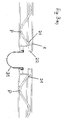
- the fasteners can be designed as drainage channels (31) at the same time (see FIGS. 3a, 3b).
- the installation profile system can by means of conventional fasteners, eg. B. Screws, clamps, clamps etc., on the substructure can be attached.
- the fastener can be directly in the Frame elements (1) or engage in the connecting elements.
- the frame elements (1) and also the connecting elements can be made of Metal, e.g. As aluminum or plastic, preferably an extruded or injection molded, weatherproof, non-brittle plastic (e.g. a synthetic rubber, rubber, acrylonitrile butadiene stryrene (ABS) plastic). Also a combination of metal and Plastic, e.g. B. Aluminum with a plastic seal is suitable.
- Metal e.g. As aluminum or plastic, preferably an extruded or injection molded, weatherproof, non-brittle plastic (e.g. a synthetic rubber, rubber, acrylonitrile butadiene stryrene (ABS) plastic).
- ABS acrylonitrile butadiene stryrene
- a combination of metal and Plastic e.g. B. Aluminum with a plastic seal is suitable.
- the frame elements can preferably have an inner strip (21) have the edges of the board to be installed in the direction of support record or support (see Fig. 2a, 2b). This has the advantage that the Plate elements (P) have only a slight play in the frame.
- Frame elements (1) with enclosed profile plates (P) can be used for this Purpose with a clamping device (41) engaging in the outer profile (22) be provided.
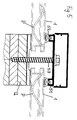
- the tensioning device (41) can be used as Screw clamping device (42) can be designed, wherein screws (43) in one, engage in the screw bar (44) inserted into the outer profile (22) (see FIG. 4a).
- the tensioning device can be on the top as a support against wind suction and / or be attached on the underside as a support against snow load.
Landscapes
- Engineering & Computer Science (AREA)
- Mechanical Engineering (AREA)
- Architecture (AREA)
- Civil Engineering (AREA)
- Structural Engineering (AREA)
- Roof Covering Using Slabs Or Stiff Sheets (AREA)
Abstract
Description
dadurch gekennzeichnet,
daß das Verlegeprofilsystem im wesentlichen aus Rahmenelementen (1) besteht, die die Ränder der Plattenelemente (P) allseitig umschließen, wobei mehrere Rahmenelemente (1) über Verbindungselemente zusammengefaßt werden und das Verlegeprofilsystem mittels üblicher Befestigungselemente auf der Unterkonstruktion (U) befestigt werden kann.
- Fig. 2a: Ausschnittsvergrößerung des Teilbereichs Y mit Profilplatte (P), innen verlaufender Leiste (21) und Außenprofil (22).
- Fig. 2b: Ausschnittsvergrößerung des Teilbereichs Z mit mit Profilplatte (P), innen verlaufender Leiste (21) und Außenprofil (22).
- Fig. 2c: Schrägansicht einer in Rahmenelemente (1) eingeschlossene Profilplatte (P) mit Außenprofil (22).
- Fig. 3a: Zwei, jeweils in Rahmenelemente (1) eingeschlossene Profilplatten (P) gezeigt im Querschnitt entsprechend der Ebene B-B, Ausschnittsvergrößerung des Teilbereichs Y (s. Fig. 1b) mit Außenprofil (22) und Verbindungselemente (31) in Form einer Drainagerinne (31).
- Fig. 3b: Schrägansicht zweier jeweils in Rahmenelemente (1) eingeschlossenen Profilplatten (P) mit Außenprofil (22), in das ein Verbindungselement (31) in Form einer Drainagerinne eingehängt ist (entsprechend Fig. 3a).
- Fig. 4a: Rahmenelemente (1) mit eingeschlossener Profilplatten (P), gezeigt im Querschnitt entsprechend der Ebene B-B, Ausschnittsvergrößerung des Teilbereichs Y (s. Fig. 1b), mit Außenprofil (22) und in das Rahmenelement (1) eingreifender Schraubspannvorrichtungen (42), wobei die Schrauben (43) in eine, in das Außenprofil (22) eingesetzte Schraubleiste (44) eingreifen
- Fig. 4b: Wie Fig. 4a jedoch mit in das Außenprofil (22) eingreifender Spannvorrichtungen (41) ohne Schraube.
- Fig. 4c: Schrägansicht einer in Rahmenelemente (1) eingeschlossenen Profilplatten (P), mit in das Außenprofil (22) eingreifender Spannvorrichtungen (41) ohne Schraube (entsprechend Fig. 4b).
- Fig. 5: Zwei Rahmenelemente (1) mit eingeschlossener Profilplatten (P), gezeigt im Querschnitt entsprechend der Ebene B-B, Ausschnittsvergrößerung des Teilbereichs Y (s. Fig. 1b), mit überbrückender Metallschiene (51), die beidseitig mit Dichtungen (52) versehenen ist, und mittels durchgeführter Schrauben (53) auf einer in der Tragrichtung verlaufenden Unterkonstruktion (U), z. B. einem Sparren, verschraubt ist.
Claims (7)
- Verlegeprofilsystem zur Befestigung von profilierten Plattenelementen (P) auf einer bestehenden Unterkonstruktion,
dadurch gekennzeichnet, daß das Verlegeprofilsystem im wesentlichen aus Rahmenelementen (1) besteht, die die Ränder der Plattenelemente (P) allseitig umschließen, wobei mehrere Rahmenelemente (1) über Verbindungselemente zusammengefaßt werden können und das Verlegeprofilsystem mittels üblicher Befestigungselemente auf der Unterkonstruktion befestigt werden kann. - Verlegeprofilsystem nach Anspruch 1, dadurch gekennzeichnet, daß die Rahmenelemente eine innen verlaufende Leiste (21) aufweisen, die die Kanten der zu verlegenden profilierten Plattenelemente (P) in Tragrichtung aufnehmen beziehungsweise stützen.
- Verlegeprofilsystem nach Anspruch 1 oder 2, dadurch gekennzeichnet, daß es für Wellplatten, vorzugsweise für solche mit sinusförmigem Profil ausgelegt ist.
- Verlegeprofilsystem nach einem oder mehreren der Ansprüche 1 bis 3, dadurch gekennzeichnet, daß die Rahmenelemente (1) ein Außenprofil (22) zur Aufnahme von Befestigungs- oder Verbindungselementen aufweisen.
- Verlegeprofilsystem nach Anspruch 4, dadurch gekennzeichnet, daß in das Außenprofil (22) Verbindungselemente eingreifen, die als Drainagerinne (31) ausgebildet sind.
- Verlegeprofilsystem nach Anspruch 4, dadurch gekennzeichnet, daß die Rahmenelemente (1) mit eingeschlossener Profilplatte (P) mit einer, in das Außenprofil (22) eingreifenden Spannvorrichtungen (41) versehen werden.
- Verlegeprofilsystem nach Anspruch 6, dadurch gekennzeichnet, daß die Spannvorrichtung als Schraubspannvorrichtung (42) ausgeführt ist, wobei Schrauben (43) in eine in das Außenprofil (22) eingesetzte Schraubleiste (44) eingreifen.
Applications Claiming Priority (2)
| Application Number | Priority Date | Filing Date | Title |
|---|---|---|---|
| DE10117999 | 2001-04-10 | ||
| DE2001117999 DE10117999A1 (de) | 2001-04-10 | 2001-04-10 | Verlegeprofilsystem für profilierte Platten |
Publications (2)
| Publication Number | Publication Date |
|---|---|
| EP1249557A2 true EP1249557A2 (de) | 2002-10-16 |
| EP1249557A3 EP1249557A3 (de) | 2003-03-26 |
Family
ID=7681171
Family Applications (1)
| Application Number | Title | Priority Date | Filing Date |
|---|---|---|---|
| EP02005467A Withdrawn EP1249557A3 (de) | 2001-04-10 | 2002-03-09 | Verlegeprofilsystem für profilierte Platten |
Country Status (2)
| Country | Link |
|---|---|
| EP (1) | EP1249557A3 (de) |
| DE (1) | DE10117999A1 (de) |
Citations (1)
| Publication number | Priority date | Publication date | Assignee | Title |
|---|---|---|---|---|
| WO1998009036A1 (en) | 1996-08-29 | 1998-03-05 | Onduline Building Products Limited | Fastener for corrugated sheeting |
Family Cites Families (6)
| Publication number | Priority date | Publication date | Assignee | Title |
|---|---|---|---|---|
| US3113434A (en) * | 1959-09-17 | 1963-12-10 | Reichhold Chemicals Inc | Roof of panel units |
| FR1254372A (fr) * | 1960-04-19 | 1961-02-17 | Dispositif de jonction de panneaux de bâtiments ou autres | |
| DE2136626A1 (de) * | 1971-07-22 | 1973-02-08 | Rheinhold & Mahla Gmbh | Abdeckung fuer grossflaechige daecher |
| DE2143171A1 (de) * | 1971-08-28 | 1973-03-01 | Fritz Haas Kg | Kaltdach, insbesondere flachdach |
| GB2103694B (en) * | 1981-08-01 | 1984-09-12 | Frederick Charles Coles | Window light |
| EP0081643A1 (de) * | 1981-12-11 | 1983-06-22 | artur fischer forschung | Abdichtung der Enden und Stösse einer aus Platten bestehenden Aussenhaut |
-
2001
- 2001-04-10 DE DE2001117999 patent/DE10117999A1/de not_active Ceased
-
2002
- 2002-03-09 EP EP02005467A patent/EP1249557A3/de not_active Withdrawn
Patent Citations (1)
| Publication number | Priority date | Publication date | Assignee | Title |
|---|---|---|---|---|
| WO1998009036A1 (en) | 1996-08-29 | 1998-03-05 | Onduline Building Products Limited | Fastener for corrugated sheeting |
Also Published As
| Publication number | Publication date |
|---|---|
| DE10117999A1 (de) | 2002-10-17 |
| EP1249557A3 (de) | 2003-03-26 |
Similar Documents
| Publication | Publication Date | Title |
|---|---|---|
| EP1734588B1 (de) | Dacheindeckung | |
| WO1993017204A1 (de) | Anputz- und schutzleiste für fensterstöcke, türstöcke oder dergleichen am übergang zu putz | |
| DE8421910U1 (de) | Dachrandverblendung | |
| WO2010051999A2 (de) | Integriertes dachsystem, befestigung von einlegeprofilen auf sandwichpaneelen mit hinterschnitt-nuten | |
| DE19526671A1 (de) | Fassade oder Dach | |
| DE3626760C2 (de) | ||
| EP1024233B1 (de) | Verlegeprofilsystem für Platten | |
| DE10117999A1 (de) | Verlegeprofilsystem für profilierte Platten | |
| DE29807808U1 (de) | Unterkonstruktion zur Halterung von Fassadenelementen | |
| EP2292864B1 (de) | Dacheindeckung mit Kunststoffziegeln | |
| WO2006074973A1 (de) | Modulare fassade für gebäude, glasauflagedichtung und schraube | |
| DE202007015479U1 (de) | Bodenbelag und Dichtungsprofil | |
| DE10120842A1 (de) | Verlegeprofilsystem für profilierte Platten | |
| EP0863271A2 (de) | Abdeckung für den Kehlbereich eines Daches | |
| DE19643529A1 (de) | Rahmenelement mit flexibler Bespannung und Bauwerk aus derartigen Rahmenelementen | |
| DE2614279A1 (de) | Fassadenlamelle aus kunststoff | |
| EP0058768A1 (de) | Verbindungs-Profilsprosse für Wellplatten | |
| EP1625266A1 (de) | Abdeckung für eine fläche von balkonen, böden, dächern oder fassaden | |
| DE202004020247U1 (de) | Wohndachfenster | |
| DE3610409C2 (de) | ||
| DE19546349A1 (de) | Mehrteiliger Flachdachabschluß für die Befestigung von Bitumen und Kunststoffbahnen | |
| DE29611015U1 (de) | Traufenabschlußelement | |
| DE4216390A1 (de) | Montageset für die Verbindung einander benachbarter Glas- oder Kunststoffplatten zur Herstellung von Dächern | |
| EP0056451A2 (de) | Wandanschlussprofil für plattenförmiges Deckmaterial | |
| DE29510106U1 (de) | Vorrichtung zur Dacheinbindung von Dachkollektoren |
Legal Events
| Date | Code | Title | Description |
|---|---|---|---|
| PUAI | Public reference made under article 153(3) epc to a published international application that has entered the european phase |
Free format text: ORIGINAL CODE: 0009012 |
|
| AK | Designated contracting states |
Kind code of ref document: A2 Designated state(s): AT BE CH CY DE DK ES FI FR GB GR IE IT LI LU MC NL PT SE TR |
|
| AX | Request for extension of the european patent |
Free format text: AL;LT;LV;MK;RO;SI |
|
| PUAL | Search report despatched |
Free format text: ORIGINAL CODE: 0009013 |
|
| AK | Designated contracting states |
Kind code of ref document: A3 Designated state(s): AT BE CH CY DE DK ES FI FR GB GR IE IT LI LU MC NL PT SE TR Designated state(s): AT BE CH CY DE DK ES FI FR GB GR IE IT LI LU MC NL PT SE TR |
|
| AX | Request for extension of the european patent |
Extension state: AL LT LV MK RO SI |
|
| RIC1 | Information provided on ipc code assigned before grant |
Ipc: 7E 04D 3/30 B Ipc: 7E 04D 3/24 B Ipc: 7E 04D 3/366 A |
|
| 17P | Request for examination filed |
Effective date: 20030515 |
|
| AKX | Designation fees paid |
Designated state(s): AT BE CH CY DE DK ES FI FR GB GR IE IT LI LU MC NL PT SE TR |
|
| RAP1 | Party data changed (applicant data changed or rights of an application transferred) |
Owner name: ROEHM GMBH |
|
| 17Q | First examination report despatched |
Effective date: 20070426 |
|
| RAP1 | Party data changed (applicant data changed or rights of an application transferred) |
Owner name: EVONIK ROEHM GMBH |
|
| RAP1 | Party data changed (applicant data changed or rights of an application transferred) |
Owner name: EVONIK ROEHM GMBH |
|
| GRAP | Despatch of communication of intention to grant a patent |
Free format text: ORIGINAL CODE: EPIDOSNIGR1 |
|
| RTI1 | Title (correction) |
Free format text: INSTALLING SYSTEM FOR CORRUGATED PANELS |
|
| STAA | Information on the status of an ep patent application or granted ep patent |
Free format text: STATUS: THE APPLICATION IS DEEMED TO BE WITHDRAWN |
|
| 18D | Application deemed to be withdrawn |
Effective date: 20091124 |