EP1249382A2 - Riegelverschluss für Nutzfahrzeuge - Google Patents
Riegelverschluss für Nutzfahrzeuge Download PDFInfo
- Publication number
- EP1249382A2 EP1249382A2 EP02007508A EP02007508A EP1249382A2 EP 1249382 A2 EP1249382 A2 EP 1249382A2 EP 02007508 A EP02007508 A EP 02007508A EP 02007508 A EP02007508 A EP 02007508A EP 1249382 A2 EP1249382 A2 EP 1249382A2
- Authority
- EP
- European Patent Office
- Prior art keywords
- bolt
- bolt lock
- lock according
- handle
- hollow profile
- Prior art date
- Legal status (The legal status is an assumption and is not a legal conclusion. Google has not performed a legal analysis and makes no representation as to the accuracy of the status listed.)
- Granted
Links
- 239000004033 plastic Substances 0.000 claims abstract description 5
- 210000000629 knee joint Anatomy 0.000 claims description 4
- 238000007688 edging Methods 0.000 claims description 3
- 239000003365 glass fiber Substances 0.000 claims description 3
- 239000004952 Polyamide Substances 0.000 claims description 2
- 229920002647 polyamide Polymers 0.000 claims description 2
- 238000001746 injection moulding Methods 0.000 description 3
- 210000003127 knee Anatomy 0.000 description 1
- 239000002184 metal Substances 0.000 description 1
- 239000000243 solution Substances 0.000 description 1
Images
Classifications
-
- E—FIXED CONSTRUCTIONS
- E05—LOCKS; KEYS; WINDOW OR DOOR FITTINGS; SAFES
- E05C—BOLTS OR FASTENING DEVICES FOR WINGS, SPECIALLY FOR DOORS OR WINDOWS
- E05C1/00—Fastening devices with bolts moving rectilinearly
- E05C1/02—Fastening devices with bolts moving rectilinearly without latching action
- E05C1/06—Fastening devices with bolts moving rectilinearly without latching action with operating handle or equivalent member moving otherwise than rigidly with the bolt
-
- B—PERFORMING OPERATIONS; TRANSPORTING
- B62—LAND VEHICLES FOR TRAVELLING OTHERWISE THAN ON RAILS
- B62D—MOTOR VEHICLES; TRAILERS
- B62D33/00—Superstructures for load-carrying vehicles
- B62D33/02—Platforms; Open load compartments
- B62D33/023—Sideboard or tailgate structures
- B62D33/027—Sideboard or tailgate structures movable
- B62D33/037—Latching means therefor
Definitions
- the invention relates to a bolt lock for commercial vehicles for locking a Drop side, door or the like against another body part of the vehicle according to the preamble of claim 1.
- Bolt locks of this type are known in a wide variety of embodiments, e.g. from DE-GM 298 07 738.8 and DE-GM 298 05 650.4. With these Bolt locks, it is important that the locking of the side wall or door with the other structural part is done without play.
- the bar consists of a bar stump and a locking member cooperating with this via a spring. This will in in the closed position, the locking member is pressed into the receptacle on the further structural part, whereby the desired backlash-free connection is achieved.
- wear of the Locking member and / or the receptacle hereby results at the same time automatic readjustment, so that even after considerable wear, it is free of play Connection is guaranteed.
- the invention had the object of a closure in the preamble of the claim 1 to simplify the defined way in this regard.
- the latch can be done in a simple manner Injection molding can be made.
- the plastic preferably consists of fiber-reinforced, in particular glass fiber reinforced, polyamide (claim 2).
- the one-piece latch is best made by injection molding when the spring part is out there is a corrugated or zigzag-shaped band (claim 3).
- the invention is of particular importance for such latch locks which are in a hollow profile formed side edging of the drop side are installed, which at the same time the Base part for the bolt lock forms and from a box-shaped part with the side protruding parallel cheeks, which is the side edge of a drop side encompass (claim 4).
- Bar stump and locking member are as cuboid blocks formed with little play within the box-shaped Can slide part of the hollow profile.
- the free end of the handle is in Top view, round and in particular semicircular design (claim 6). It lies there Handle well when opening and closing.
- the closure has the locking member as an engaging member projecting with a side head Bolt emerging from a slot in a side wall of the box-shaped part of the hollow profile protrudes (claim 7).
- Knee joint of the knee lever with respect to the two outer articulation points of the same in one Dead center position is (claim 8).
- the closed position of the handle can additionally or alternatively by means of a disengageable locking device be secured (claim 9).
- the locking device is preferably a spring-loaded seesaw (claim 10).
- the further structural part preferably consists of a stanchion or of a corner standing side wall with a hollow profile as a lateral border (claim 11).
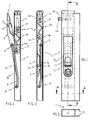
- the base part of the closure consists of a hollow profile 1 with a box-shaped part 2 and two of them laterally protruding parallel cheeks 3, which in the application Reach over the side edge of a side wall and are fastened to it.
- a bolt is slidably mounted, which consists of a bar stub 4a, a zigzag spring 4b and a locking member 4c and a bolt 4d with head 4e, which is the actual locking member.
- the latch stub 4a, the spring 4b and the locking member 4c are made in one piece Glass fiber reinforced poyamide made by injection molding.
- the bolt 4d with its head 4e on the other hand consists of metal and is in a corresponding hole in the locking member 4c attached, for example screwed in with a thread.
- the bolt 4d also jumps his head 4e laterally from a slot 5, which in a side wall of the box-shaped Part 2 of the hollow profile 1 is incorporated. He works with a corresponding recording of the Partly together, against which a side wall provided with the hollow profile shown is locked shall be.
- the latch stub 4a and the locking member 4c are cuboid and fit into the cavity 2 of the hollow profile 1 with little play.
- the drive of the bolt consists of a handlebar 6 and a handle 7.
- the handlebar 6 is on the one hand by means of an axis 8 in the side walls of the box-shaped part 2 of the Hollow profile 1 and on the other hand articulated by means of an axis 9 on the handle 7, which is in turn articulated on the stump 4a by means of an axis 10.
- the link 6 and the part 7a of the handle 7 lying between the axes 9 and 10 form together a toggle lever, the axis 9 representing the knee joint, which is shown in FIG. 3 shown closed position with respect to axes 8 and 10 is in an over-dead center position, which fixes the closed position of the closure.
- the handle 7 lies in the closed position in an opening 15 corresponding to its shape the front wall of the box-shaped part 2 of the hollow profile 1 and aligned in the Closed position with the surface of the hollow profile 1.
- the free end 7b of the handle 7 is semicircular, so that when opening the closure the handle well in the Operator's hand lies.
Landscapes
- Engineering & Computer Science (AREA)
- Mechanical Engineering (AREA)
- Chemical & Material Sciences (AREA)
- Combustion & Propulsion (AREA)
- Transportation (AREA)
- Lock And Its Accessories (AREA)
- Handcart (AREA)
- Clamps And Clips (AREA)
- Connection Of Plates (AREA)
Abstract
Description
Claims (11)
- Riegelverschluß für Nutzfahrzeuge zum Verriegeln einer Bordwand, Türe o.dgl. gegen ein weiteres Aufbauteil des Fahrzeugs, wobei der Riegel (4) in einem Basisteil (1) linear geführt ist und mittels eines mechanischen Antriebs (6,7) gegen eine am weiteren Aufbauteil vorgesehene Aufnahme verriegelbar ist, wobei weiterhin der Antrieb aus einem einerseits am Riegel (4) und andererseits am Basisteil (1) angelenkten Kniehebel (6,7a) besteht, von dem ein Kniehebelglied (7a) über das Kniegelenk (9) hinaus verlängert und dort als Handhabe (7) ausgebildet ist, und wobei außerdem der Riegel (4) aus einem Riegelstumpf (4a) und einem mit diesem über eine Feder (4b) zusammenwirkenden Verriegelungsglied (4c) besteht, dadurch gekennzeichnet, daß der gesamte Riegel (4) einstückig ausgebildet ist und aus Kunststoff besteht.
- Riegelverschluß nach Anspruch 1, dadurch gekennzeichnet, daß der Kunststoff aus faserverstärktem, insbesodere glasfaserverstärktem, Polyamid besteht.
- Riegelverschluß nach Anspruch 1 oder 2, dadurch gekennzeichnet, daß die Feder (4b) des Riegels (4) aus einem gewellten oder zick-zack-förmigen Band besteht.
- Riegelverschluß nach einem der vorhergehenden Ansprüche, dadurch gekennzeichnet, daß der Riegelverschluß in eine als Hohlprofil (1) ausgebildete seitliche Einfassung der Bordwand eingebaut ist, welche Einfassung gleichzeitig das Basisteil des Riegelverschlusses bildet und aus einem kastenförmigen Teil (2) mit seitlich davon abstehenden parallelen Wangen (3) besteht.
- Riegelverschluß nach Anspruch 4, dadurch gekennzeichnet, daß in der Schließstellung die Handhabe (7) in einer der Form der Handhabe (7) entsprechenden Öffnung (15) der Einfassung (1) ruht und ihre Oberfläche mit derjenigen der Einfassung (1) fluchtet.
- Riegelverschluß nach Anspruch 5, dadurch gekennzeichnet, daß das freie Ende (7b) der Handhabe (7), in Draufsicht, rund und insbesondere halbkreisförmig ausgebildet ist.
- Riegelverschluß nach einem der Ansprüch 4, 5 oder 6, dadurch gekennzeichnet, daß das Verriegelungsglied 4c als Verriegelungsorgan einen querverlaufenden Bolzen 4d mit Kopf 4e trägt, der aus einem Schlitz 5 im kastenförmigen Teil 2 des Hohlprofils 1 vorspringt.
- Riegelverschluß nach einem der vorhergehenden Ansprüche, dadurch gekennzeichnet, daß in der Schließstellung sich das Kniegelenk (9) des Kniehebels (6,7a) bezüglich der beiden äußeren Anlenkpunkte (8,10) des Kniehebels (6,7a) in einer Übertotpunktlage befindet.
- Riegelverschluß nach einem der vorhergehenden Ansprüche, dadurch gekennzeichnet, daß in der Schließstellung die Handhabe (7) mittels einer ausrückbaren Einrastvorrichtung (12) gesichert ist.
- Riegelverschluß nach Anspruch 9, dadurch gekennzeichnet, daß die Einrastvorrichtung aus einer in einer Mulde (11) der Handhabe (7) angeordneten federbelasteten Wippe (12) besteht.
- Riegelverschluß nach einem der vorhergehenden Ansprüche, dadurch gekennzeichnet, daß das weitere Aufbauteil aus einer Runge oder aus einer über Eck stehende Bordwand mit einem Hohlprofil als seitliche Einfassung besteht.
Applications Claiming Priority (2)
| Application Number | Priority Date | Filing Date | Title |
|---|---|---|---|
| DE20106452U DE20106452U1 (de) | 2001-04-13 | 2001-04-13 | Riegelverschluß für Nutzfahrzeuge |
| DE20106452U | 2001-04-13 |
Publications (3)
| Publication Number | Publication Date |
|---|---|
| EP1249382A2 true EP1249382A2 (de) | 2002-10-16 |
| EP1249382A3 EP1249382A3 (de) | 2004-04-14 |
| EP1249382B1 EP1249382B1 (de) | 2012-03-07 |
Family
ID=7955701
Family Applications (1)
| Application Number | Title | Priority Date | Filing Date |
|---|---|---|---|
| EP02007508A Expired - Lifetime EP1249382B1 (de) | 2001-04-13 | 2002-04-02 | Riegelverschluss für Nutzfahrzeuge |
Country Status (4)
| Country | Link |
|---|---|
| EP (1) | EP1249382B1 (de) |
| AT (1) | ATE548248T1 (de) |
| DE (1) | DE20106452U1 (de) |
| ES (1) | ES2380813T3 (de) |
Families Citing this family (2)
| Publication number | Priority date | Publication date | Assignee | Title |
|---|---|---|---|---|
| DE202009001986U1 (de) * | 2009-03-20 | 2009-05-14 | F. Hesterberg & Söhne Gmbh & Co. Kg | Bordwandverschluss an einem Nutzfahrzeugaufbau |
| SE539883C2 (sv) * | 2016-05-18 | 2018-01-02 | Rosén Göran | Anordning vid sidostolpe för lastflak |
Citations (3)
| Publication number | Priority date | Publication date | Assignee | Title |
|---|---|---|---|---|
| DE9217849U1 (de) | 1992-01-15 | 1993-02-25 | Allibert Manutention, Neuilly-sur-Seine | Schließmechanismus für Türen oder Klappwände |
| DE29807738U1 (de) | 1998-04-29 | 1998-07-23 | F. Hesterberg & Söhne GmbH & Co KG, 58256 Ennepetal | Seitliche Einfassung für Bordwände von Nutzfahrzeugen mit integriertem Riegelverschluß |
| DE29815650U1 (de) | 1998-08-31 | 1998-10-22 | F. Hesterberg & Söhne GmbH & Co KG, 58256 Ennepetal | Seitliche Einfassung für Bordwände von Nutzfahrzeugen mit integriertem Riegelverschluß |
Family Cites Families (2)
| Publication number | Priority date | Publication date | Assignee | Title |
|---|---|---|---|---|
| DE3940061C2 (de) * | 1989-12-04 | 1994-06-30 | Bauer Hans Juergen | Türschloß |
| SE468472B (sv) * | 1991-06-19 | 1993-01-25 | Vbg Prod Ab | Flakstolpe samt saett att montera en laas- och paaverkningsmekanism i densamma |
-
2001
- 2001-04-13 DE DE20106452U patent/DE20106452U1/de not_active Expired - Lifetime
-
2002
- 2002-04-02 AT AT02007508T patent/ATE548248T1/de active
- 2002-04-02 ES ES02007508T patent/ES2380813T3/es not_active Expired - Lifetime
- 2002-04-02 EP EP02007508A patent/EP1249382B1/de not_active Expired - Lifetime
Patent Citations (3)
| Publication number | Priority date | Publication date | Assignee | Title |
|---|---|---|---|---|
| DE9217849U1 (de) | 1992-01-15 | 1993-02-25 | Allibert Manutention, Neuilly-sur-Seine | Schließmechanismus für Türen oder Klappwände |
| DE29807738U1 (de) | 1998-04-29 | 1998-07-23 | F. Hesterberg & Söhne GmbH & Co KG, 58256 Ennepetal | Seitliche Einfassung für Bordwände von Nutzfahrzeugen mit integriertem Riegelverschluß |
| DE29815650U1 (de) | 1998-08-31 | 1998-10-22 | F. Hesterberg & Söhne GmbH & Co KG, 58256 Ennepetal | Seitliche Einfassung für Bordwände von Nutzfahrzeugen mit integriertem Riegelverschluß |
Also Published As
| Publication number | Publication date |
|---|---|
| ES2380813T3 (es) | 2012-05-18 |
| DE20106452U1 (de) | 2001-06-21 |
| EP1249382A3 (de) | 2004-04-14 |
| ATE548248T1 (de) | 2012-03-15 |
| EP1249382B1 (de) | 2012-03-07 |
Similar Documents
| Publication | Publication Date | Title |
|---|---|---|
| DE3445000C2 (de) | ||
| DE202018105217U1 (de) | Antriebsschlitten für ein Tor sowie Torantrieb | |
| EP0585952B1 (de) | Riegelspannverschluss für abklappbare Bordwände von Lastfahrzeugen | |
| DE29807738U1 (de) | Seitliche Einfassung für Bordwände von Nutzfahrzeugen mit integriertem Riegelverschluß | |
| EP0831001A1 (de) | Hängerunge | |
| EP1249382B1 (de) | Riegelverschluss für Nutzfahrzeuge | |
| EP0671529A1 (de) | Verriegelungsvorrichtung für einen schwenkbar gelagerten Aufbewahrungsbehälter in einem Fahrzeug | |
| DE3630406C2 (de) | ||
| DE10100763B4 (de) | Einsteckschloss mit Kunststoffriegel | |
| DE3546009A1 (de) | Vorrichtung zur arretierung von kfz-tueren in einer teiloffenen montagestellung | |
| EP0953496B1 (de) | Handhabe eines Verschlusses für Türen, Klappen oder dergleichen von Nutzfahrzeugaufbauten | |
| DE2144756B2 (de) | Fernbetatigungsvornchtung, ins besondere fur Kraftfahrzeugturschlosser | |
| DE3442835C2 (de) | Verschlußvorrichtung für eine abklappbare Abdeckplatte einer Gehäuseöffnung an einem Haushaltgerät | |
| DE3437439C2 (de) | Schlüssel zur Betätigung eines Schlosses an einem Kraftfahrzeug | |
| DE19541942C1 (de) | Rechts und links verwendbares Türschloß | |
| DE770750T1 (de) | Bedienungsschloss für Türtreibstangenbeschläge | |
| DE60206710T2 (de) | Schlüssel mit gelenkigem Schlüsselbart | |
| DE3515920C2 (de) | Staubsauger mit einem längsgeteilten Handgriff | |
| DE9314627U1 (de) | Gehäuse für elektrische Geräte | |
| EP0761480B1 (de) | Kugelkopfkupplung | |
| DE60004909T2 (de) | Schlüsselhalter mit herausklappbarem Schlüssel für Kraftfahrzeuge | |
| DE2429363C3 (de) | Schnappverschluß für die Frontscheibe eines Arbeitsfahrzeuges | |
| DE29712719U1 (de) | Scharnierrollenhalter für Sektionaltore | |
| EP1658413B1 (de) | Bodentürschliesser | |
| DE9101555U1 (de) | Spannvorrichtung |
Legal Events
| Date | Code | Title | Description |
|---|---|---|---|
| PUAI | Public reference made under article 153(3) epc to a published international application that has entered the european phase |
Free format text: ORIGINAL CODE: 0009012 |
|
| AK | Designated contracting states |
Kind code of ref document: A2 Designated state(s): AT BE CH CY DE DK ES FI FR GB GR IE IT LI LU MC NL PT SE TR |
|
| AX | Request for extension of the european patent |
Free format text: AL;LT;LV;MK;RO;SI |
|
| PUAL | Search report despatched |
Free format text: ORIGINAL CODE: 0009013 |
|
| AK | Designated contracting states |
Kind code of ref document: A3 Designated state(s): AT BE CH CY DE DK ES FI FR GB GR IE IT LI LU MC NL PT SE TR |
|
| AX | Request for extension of the european patent |
Extension state: AL LT LV MK RO SI |
|
| 17P | Request for examination filed |
Effective date: 20041012 |
|
| AKX | Designation fees paid |
Designated state(s): AT BE CH CY DE DK ES FI FR GB GR IE IT LI LU MC NL PT SE TR |
|
| GRAP | Despatch of communication of intention to grant a patent |
Free format text: ORIGINAL CODE: EPIDOSNIGR1 |
|
| GRAS | Grant fee paid |
Free format text: ORIGINAL CODE: EPIDOSNIGR3 |
|
| GRAA | (expected) grant |
Free format text: ORIGINAL CODE: 0009210 |
|
| AK | Designated contracting states |
Kind code of ref document: B1 Designated state(s): AT BE CH CY DE DK ES FI FR GB GR IE IT LI LU MC NL PT SE TR |
|
| REG | Reference to a national code |
Ref country code: GB Ref legal event code: FG4D Free format text: NOT ENGLISH |
|
| REG | Reference to a national code |
Ref country code: AT Ref legal event code: REF Ref document number: 548248 Country of ref document: AT Kind code of ref document: T Effective date: 20120315 Ref country code: CH Ref legal event code: EP |
|
| REG | Reference to a national code |
Ref country code: DE Ref legal event code: R082 Ref document number: 50215402 Country of ref document: DE Representative=s name: CHRISTOPHERSEN & PARTNER, PATENTANWAELTE, DE Ref country code: DE Ref legal event code: R082 Ref document number: 50215402 Country of ref document: DE Representative=s name: BUNGARTZ CHRISTOPHERSEN PARTNERSCHAFT MBB PATE, DE |
|
| REG | Reference to a national code |
Ref country code: IE Ref legal event code: FG4D Free format text: LANGUAGE OF EP DOCUMENT: GERMAN |
|
| REG | Reference to a national code |
Ref country code: SE Ref legal event code: TRGR |
|
| REG | Reference to a national code |
Ref country code: DE Ref legal event code: R096 Ref document number: 50215402 Country of ref document: DE Effective date: 20120503 |
|
| REG | Reference to a national code |
Ref country code: ES Ref legal event code: FG2A Ref document number: 2380813 Country of ref document: ES Kind code of ref document: T3 Effective date: 20120518 |
|
| REG | Reference to a national code |
Ref country code: NL Ref legal event code: VDEP Effective date: 20120307 |
|
| PG25 | Lapsed in a contracting state [announced via postgrant information from national office to epo] |
Ref country code: NL Free format text: LAPSE BECAUSE OF FAILURE TO SUBMIT A TRANSLATION OF THE DESCRIPTION OR TO PAY THE FEE WITHIN THE PRESCRIBED TIME-LIMIT Effective date: 20120307 |
|
| PG25 | Lapsed in a contracting state [announced via postgrant information from national office to epo] |
Ref country code: GR Free format text: LAPSE BECAUSE OF FAILURE TO SUBMIT A TRANSLATION OF THE DESCRIPTION OR TO PAY THE FEE WITHIN THE PRESCRIBED TIME-LIMIT Effective date: 20120608 Ref country code: FI Free format text: LAPSE BECAUSE OF FAILURE TO SUBMIT A TRANSLATION OF THE DESCRIPTION OR TO PAY THE FEE WITHIN THE PRESCRIBED TIME-LIMIT Effective date: 20120307 |
|
| PG25 | Lapsed in a contracting state [announced via postgrant information from national office to epo] |
Ref country code: CY Free format text: LAPSE BECAUSE OF FAILURE TO SUBMIT A TRANSLATION OF THE DESCRIPTION OR TO PAY THE FEE WITHIN THE PRESCRIBED TIME-LIMIT Effective date: 20120307 |
|
| BERE | Be: lapsed |
Owner name: F. HESTERBERG & SOHNE G.M.B.H. & CO. KG Effective date: 20120430 |
|
| PG25 | Lapsed in a contracting state [announced via postgrant information from national office to epo] |
Ref country code: PT Free format text: LAPSE BECAUSE OF FAILURE TO SUBMIT A TRANSLATION OF THE DESCRIPTION OR TO PAY THE FEE WITHIN THE PRESCRIBED TIME-LIMIT Effective date: 20120709 Ref country code: MC Free format text: LAPSE BECAUSE OF NON-PAYMENT OF DUE FEES Effective date: 20120430 |
|
| REG | Reference to a national code |
Ref country code: CH Ref legal event code: PL |
|
| PLBE | No opposition filed within time limit |
Free format text: ORIGINAL CODE: 0009261 |
|
| STAA | Information on the status of an ep patent application or granted ep patent |
Free format text: STATUS: NO OPPOSITION FILED WITHIN TIME LIMIT |
|
| REG | Reference to a national code |
Ref country code: IE Ref legal event code: MM4A |
|
| PG25 | Lapsed in a contracting state [announced via postgrant information from national office to epo] |
Ref country code: IE Free format text: LAPSE BECAUSE OF NON-PAYMENT OF DUE FEES Effective date: 20120402 Ref country code: DK Free format text: LAPSE BECAUSE OF FAILURE TO SUBMIT A TRANSLATION OF THE DESCRIPTION OR TO PAY THE FEE WITHIN THE PRESCRIBED TIME-LIMIT Effective date: 20120307 Ref country code: CH Free format text: LAPSE BECAUSE OF NON-PAYMENT OF DUE FEES Effective date: 20120430 Ref country code: BE Free format text: LAPSE BECAUSE OF NON-PAYMENT OF DUE FEES Effective date: 20120430 Ref country code: LI Free format text: LAPSE BECAUSE OF NON-PAYMENT OF DUE FEES Effective date: 20120430 |
|
| 26N | No opposition filed |
Effective date: 20121210 |
|
| REG | Reference to a national code |
Ref country code: DE Ref legal event code: R097 Ref document number: 50215402 Country of ref document: DE Effective date: 20121210 |
|
| REG | Reference to a national code |
Ref country code: AT Ref legal event code: MM01 Ref document number: 548248 Country of ref document: AT Kind code of ref document: T Effective date: 20120402 |
|
| PG25 | Lapsed in a contracting state [announced via postgrant information from national office to epo] |
Ref country code: AT Free format text: LAPSE BECAUSE OF NON-PAYMENT OF DUE FEES Effective date: 20120402 |
|
| PG25 | Lapsed in a contracting state [announced via postgrant information from national office to epo] |
Ref country code: TR Free format text: LAPSE BECAUSE OF FAILURE TO SUBMIT A TRANSLATION OF THE DESCRIPTION OR TO PAY THE FEE WITHIN THE PRESCRIBED TIME-LIMIT Effective date: 20120307 |
|
| PG25 | Lapsed in a contracting state [announced via postgrant information from national office to epo] |
Ref country code: LU Free format text: LAPSE BECAUSE OF NON-PAYMENT OF DUE FEES Effective date: 20120402 |
|
| PGFP | Annual fee paid to national office [announced via postgrant information from national office to epo] |
Ref country code: GB Payment date: 20140423 Year of fee payment: 13 |
|
| PGFP | Annual fee paid to national office [announced via postgrant information from national office to epo] |
Ref country code: SE Payment date: 20140423 Year of fee payment: 13 Ref country code: ES Payment date: 20140417 Year of fee payment: 13 Ref country code: IT Payment date: 20140428 Year of fee payment: 13 Ref country code: DE Payment date: 20140430 Year of fee payment: 13 Ref country code: FR Payment date: 20140416 Year of fee payment: 13 |
|
| REG | Reference to a national code |
Ref country code: DE Ref legal event code: R082 Ref document number: 50215402 Country of ref document: DE Representative=s name: BUNGARTZ CHRISTOPHERSEN PARTNERSCHAFT MBB PATE, DE |
|
| REG | Reference to a national code |
Ref country code: DE Ref legal event code: R119 Ref document number: 50215402 Country of ref document: DE |
|
| REG | Reference to a national code |
Ref country code: SE Ref legal event code: EUG |
|
| GBPC | Gb: european patent ceased through non-payment of renewal fee |
Effective date: 20150402 |
|
| PG25 | Lapsed in a contracting state [announced via postgrant information from national office to epo] |
Ref country code: DE Free format text: LAPSE BECAUSE OF NON-PAYMENT OF DUE FEES Effective date: 20151103 Ref country code: GB Free format text: LAPSE BECAUSE OF NON-PAYMENT OF DUE FEES Effective date: 20150402 Ref country code: IT Free format text: LAPSE BECAUSE OF NON-PAYMENT OF DUE FEES Effective date: 20150402 |
|
| REG | Reference to a national code |
Ref country code: FR Ref legal event code: ST Effective date: 20151231 |
|
| PG25 | Lapsed in a contracting state [announced via postgrant information from national office to epo] |
Ref country code: SE Free format text: LAPSE BECAUSE OF NON-PAYMENT OF DUE FEES Effective date: 20150403 Ref country code: FR Free format text: LAPSE BECAUSE OF NON-PAYMENT OF DUE FEES Effective date: 20150430 |
|
| REG | Reference to a national code |
Ref country code: ES Ref legal event code: FD2A Effective date: 20160527 |
|
| PG25 | Lapsed in a contracting state [announced via postgrant information from national office to epo] |
Ref country code: ES Free format text: LAPSE BECAUSE OF NON-PAYMENT OF DUE FEES Effective date: 20150403 |