EP1246701B1 - A container assembly having a support bridge - Google Patents
A container assembly having a support bridge Download PDFInfo
- Publication number
- EP1246701B1 EP1246701B1 EP00961985.9A EP00961985A EP1246701B1 EP 1246701 B1 EP1246701 B1 EP 1246701B1 EP 00961985 A EP00961985 A EP 00961985A EP 1246701 B1 EP1246701 B1 EP 1246701B1
- Authority
- EP
- European Patent Office
- Prior art keywords
- container
- lid
- swinging bucket
- neck
- bucket
- Prior art date
- Legal status (The legal status is an assumption and is not a legal conclusion. Google has not performed a legal analysis and makes no representation as to the accuracy of the status listed.)
- Expired - Lifetime
Links
- 239000004743 Polypropylene Substances 0.000 claims description 4
- 239000004033 plastic Substances 0.000 claims description 3
- 229920003023 plastic Polymers 0.000 claims description 3
- 229920000515 polycarbonate Polymers 0.000 claims description 2
- 239000004417 polycarbonate Substances 0.000 claims description 2
- 229920000139 polyethylene terephthalate Polymers 0.000 claims description 2
- 239000005020 polyethylene terephthalate Substances 0.000 claims description 2
- -1 polypropylene Polymers 0.000 claims description 2
- 229920001155 polypropylene Polymers 0.000 claims description 2
- 229920000379 polypropylene carbonate Polymers 0.000 claims description 2
- 238000005119 centrifugation Methods 0.000 description 6
- 239000000463 material Substances 0.000 description 6
- 239000008280 blood Substances 0.000 description 4
- 210000004369 blood Anatomy 0.000 description 4
- 239000007788 liquid Substances 0.000 description 3
- 238000000071 blow moulding Methods 0.000 description 2
- 239000003562 lightweight material Substances 0.000 description 2
- 230000003014 reinforcing effect Effects 0.000 description 2
- 238000005452 bending Methods 0.000 description 1
- 239000000470 constituent Substances 0.000 description 1
- 230000001419 dependent effect Effects 0.000 description 1
- 230000005484 gravity Effects 0.000 description 1
- 230000002706 hydrostatic effect Effects 0.000 description 1
- 238000004519 manufacturing process Methods 0.000 description 1
- 239000002184 metal Substances 0.000 description 1
- 238000000034 method Methods 0.000 description 1
- 239000002245 particle Substances 0.000 description 1
- 239000007787 solid Substances 0.000 description 1
- 229910001220 stainless steel Inorganic materials 0.000 description 1
- 239000010935 stainless steel Substances 0.000 description 1
- 230000007704 transition Effects 0.000 description 1
Images


Classifications
-
- B—PERFORMING OPERATIONS; TRANSPORTING
- B01—PHYSICAL OR CHEMICAL PROCESSES OR APPARATUS IN GENERAL
- B01L—CHEMICAL OR PHYSICAL LABORATORY APPARATUS FOR GENERAL USE
- B01L3/00—Containers or dishes for laboratory use, e.g. laboratory glassware; Droppers
- B01L3/50—Containers for the purpose of retaining a material to be analysed, e.g. test tubes
- B01L3/502—Containers for the purpose of retaining a material to be analysed, e.g. test tubes with fluid transport, e.g. in multi-compartment structures
- B01L3/5021—Test tubes specially adapted for centrifugation purposes
-
- B—PERFORMING OPERATIONS; TRANSPORTING
- B04—CENTRIFUGAL APPARATUS OR MACHINES FOR CARRYING-OUT PHYSICAL OR CHEMICAL PROCESSES
- B04B—CENTRIFUGES
- B04B5/00—Other centrifuges
- B04B5/04—Radial chamber apparatus for separating predominantly liquid mixtures, e.g. butyrometers
- B04B5/0407—Radial chamber apparatus for separating predominantly liquid mixtures, e.g. butyrometers for liquids contained in receptacles
- B04B5/0414—Radial chamber apparatus for separating predominantly liquid mixtures, e.g. butyrometers for liquids contained in receptacles comprising test tubes
- B04B5/0421—Radial chamber apparatus for separating predominantly liquid mixtures, e.g. butyrometers for liquids contained in receptacles comprising test tubes pivotably mounted
Definitions
- the present invention relates to a container assembly having a support bridge that is capable of preventing collapse of the container during centrifugation.
- a lid is positioned on top of the container, and the support bridge is disposed between the lid and an upper portion of the container.
- a centrifuge instrument is a device by which liquid samples may be subjected to a centrifugal force.
- Swinging bucket centrifuge systems are well known in the centrifuge art.
- the rotor in such a system is adapted to receive a bucket that hangs from the rotor body. When the rotor is at rest, the bucket hangs in a generally vertical position. When the rotor is accelerated, the bucket swings from its rest position to a horizontal position.
- US 3,938,735 A and US 4,190,196 A relate to so-called fixed angle centrifuge systems not utilizing swinging buckets.
- Straight tubes having no neck are used for centrifugation.
- the upper parts of the tubes are sealed by screw means having laterally protruding parts overlapping the upper tube portion.
- WO 94/27879 A1 and WO 92/18390 A1 disclose swinging bucket centrifuge systems utilizing a force transmitting member designed such as to distribute the bending and compressing components of the centrifugal body force generated during centrifugation into the transition portion of the tube containing the sample to be centrifuged.
- the tube has to be filled with liquid in order that a hydrostatic counter-force can be generated which withstands and opposes the centrifugal body force.
- U.S. Patent No. 5,591,114 to Romanauskas which is incorporated herein by reference, discloses a swinging bucket centrifuge rotor.
- the body of the rotor has at least one pair of confronting planar sidewalls that are circumferentially spaced apart to define a generally axially extending slot.
- Each planar sidewall has a trunnion pin mounted thereon, and the trunnion pins as a pair serve to receive a swinging bucket.
- U.S. Patent No. 5,624,370 to Romanauskas which is incorporated herein by reference, discloses a bucket for use in a swinging bucket centrifuge rotor.
- the bucket has a cylindrical body with a pair of planar abutments formed on the body. The abutments are diametrically disposed on the body.
- a slot is formed between each abutment and a portion of the body of the bucket, and each slot has a groove.
- the bucket is installed on a rotor by lowering the bucket onto a pair of rotor trunnion pins such that each trunnion pin is received within a groove defined on a respective abutment.
- a container for use in a swinging bucket centrifuge system and made of a rigid material is generally cylindrical in form.
- a swinging bucket can also define a generally rectangular volume within which a flexible or non-cylindrical container can be held. Such an arrangement is commonly used for holding blood bags for centrifugation of blood.
- the centrifugal force that advantageously serves to separate a liquid sample into its constituent parts also acts upon the container that holds the sample.
- the container must be capable of withstanding this force otherwise it will be disfigured or destroyed. For example, if a blood bag is not substantially full during centrifugation, the unfilled portion of the bag will crease and fold into the remainder of the bag and blood particles can become lodged in a crease. Even in the case of a more rigid container, the structural integrity of the container must be sufficient to ensure that it does not collapse under the stress of centrifugal force.
- the invention relates to a centrifuge system as claimed in claim 1. Preferred embodiments are described in the dependent claims.
- the member also denoted as a support bridge, to secure its position has an aperture for securing the lid and a counter bore defining a flange that engages an edge of the lid.
- a lip formed at either end of the bridge engages a respective edge of a swinging bucket in which the container is disposed during centrifugation.
- the container includes a chamber that can have a non-cylindrical form.
- the chamber can be a bag.
- the present invention permits the use of a container made of an inexpensive, lightweight material.
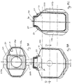
- FIG. 1 is an exploded view of a container assembly 5 for use in a centrifuge system in accordance with the present invention.
- the assembly includes a container 10, a support bridge 20, and a lid 50.
- an o-ring 30 and an insert plug 40 can be included.
- Container 10 has a chamber 8, a shoulder 12, and a neck 15 with a threaded surface and an opening through which chamber 8 is accessed.
- Lid 50 has a threaded surface that engages the threads of neck 15.
- o-ring 30 is positioned on the circumference of insert plug 40, which is inserted into the opening of container 10.
- Lid 50 with the assistance of insert plug 40 and o-ring 30, seals container 10.
- Neck 15 could have a threaded interior surface and lid 50 could have a threaded exterior surface, or vice versa.
- the threaded surfaces are not essential, and lid 50 can seal container 10 in any suitable manner.
- support bridge 20 prevents lid 50, insert plug 40 and o-ring 30, and also neck 15 and shoulder 12, from collapsing container 10 when they are subjected to centrifugal forces. It can be made of any material capable of withstanding the centrifugal forces.
- support bridge 20 is a collar, made of polypropylene, disposed about neck 15.
- Figs. 2A through 2C are, respectively, a top planar view, a front sectional view and a side sectional view of the support bridge 20 shown in Fig. 1 .
- Support bridge 20 is substantially reverse U-shaped. It has a substantially horizontal portion 27 with an aperture 26 that receives the container lid 50 ( Fig. 1 ) and a counter bore defining a lip or flange 22 that engages an edge of lid 50.
- a vertically sloping portion 28 substantially conforms to the contour of the container shoulder 12 ( Fig. 1 ). Lip 24 engages an edge of a structure within which container 10 ( Fig. 1 ) is held.
- support bridge 20 allows for container 10 to be made of an inexpensive, lightweight material.
- container 10 can be manufactured of any plastic including polyethyleneterephthalate, polypropylene, or polycarbonate, and its walls can be as thin as 1 millimeter.
- container 10 can be manufactured of any conventional material, including a metal such as stainless steel.
- Support bridge 20 also allows for container 10 to be manufactured by an inexpensive process such as blow molding.
- support bridge 20 permits chamber 8 to have either a cylindrical or non-cylindrical form.
- chamber 8 has a non-cylindrical form that permits a greater volume of material to be centrifuged as shown in the discussion accompanying Fig. 5 .
- Figs. 3A through 3C are, respectively, a top planar view, a front sectional view and a side sectional view of the container assembly shown in Fig. 1 held in a swinging bucket 100 for use in a swinging bucket centrifuge system.
- a non-cylindrical bucket such as swinging bucket 100 is sometimes referred to as a "rectangular bucket", although its footprint is not truly a quadrilateral.
- Swinging bucket 100 includes slots 110a and 110b that slide over trunnion pins ( Fig. 4 , reference 230a and 230b) for mounting on a swinging centrifuge rotor ( Fig. 4 , reference 300).
- Swinging bucket 100 can be a solid unit, a basket or merely a frame. In this application it serves as a holder for container 10.
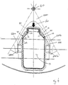
- Fig. 4 is a horizontal sectional view as would be seen along line C-C of Fig. 3B showing the assembled container assembly of Fig. 1 during a centrifuge operation.
- a rotor 200 is adapted for rotational motion within a centrifuge instrument about a vertical axis of rotation 210.
- Rotor 200 includes a pair of radially extending arms 220a and 220b with corresponding trunnion pins 230a and 230b to accommodate swinging bucket 100.
- centrifugal force 240 pushes lid 50, neck 15 and shoulder 12 toward chamber 8 of container 10.
- centrifugal force 240 can be many times the normal force of gravity, placing a tremendous strain on container 10.
- Support bridge 20 is a member positioned between lid 50 and swinging bucket 100 for supporting lid 50, neck 15 and shoulder 12, and preventing centrifugal force 240 from collapsing container 10.
- the support of neck 15 and shoulder 12 is accomplished through the engagement of lid 50 and neck 15.
- the centrifugal force 240 is transferred from lid 50 to swinging bucket 100.
- support bridge 20 has an aperture into which lid 50 is set, a counter bore defining a lip or flange 22 that engages an edge 52 of lid 50, and a lip 24 that engages an edge 102 of swinging bucket 100.
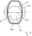
- Fig. 5 is a horizontal sectional view as would be seen along line D-D of Fig. 3B showing the advantage of chamber 8 having a non-cylindrical form.
- a cylinder held within swinging bucket 100 would be limited to having a diameter 400 and therefore, a footprint represented by the non-shaded area 410.
- a non-cylindrical footprint can extend further, beyond diameter 400 into the shaded area 420.
- a cylindrical configuration cannot take advantage of shaded area 420. Accordingly, a non-cylindrical chamber can hold a greater volume than a cylindrical chamber.
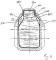
- Fig. 6 shows a swinging bucket 100 holding another embodiment of a container assembly of the present invention.
- a container 510 is comprised of a bag 508 and a neck 515 with a threaded surface and an opening through which bag 508 can be accessed.
- neck 515 is ultrasonically welded to bag 508.
- an o-ring 530 is positioned on the circumference of insert plug 540, which is inserted into the opening of container 510.
- Lid 550 has a threaded surface that engages the threads of neck 515.
- Lid 550 with the assistance of insert plug 540 and o-ring 530, seals container 510.
- Neck 515 could have a threaded interior surface and lid 550 could have a threaded exterior surface, or vice versa.
- the threaded surfaces are not essential, and lid 550 can seal container 510 in any suitable manner.
- Support bridge 520 is a member positioned between lid 550 and swinging bucket 100 for supporting lid 550 and preventing centrifugal forces from collapsing container 510. Thus, the centrifugal force is transferred from lid 550 to swinging bucket 100.
- support bridge 520 has an aperture into which lid 550 is set, a counter bore defining a lip or flange 522 that engages an edge 552 of lid 550, and a lip 524 that engages an edge 102 of swinging bucket 100.
Landscapes
- Health & Medical Sciences (AREA)
- Chemical & Material Sciences (AREA)
- Analytical Chemistry (AREA)
- General Health & Medical Sciences (AREA)
- Hematology (AREA)
- Clinical Laboratory Science (AREA)
- Chemical Kinetics & Catalysis (AREA)
- Centrifugal Separators (AREA)
- External Artificial Organs (AREA)
- Details Of Rigid Or Semi-Rigid Containers (AREA)
Applications Claiming Priority (3)
| Application Number | Priority Date | Filing Date | Title |
|---|---|---|---|
| US14199599P | 1999-07-01 | 1999-07-01 | |
| US141995P | 1999-07-01 | ||
| PCT/US2000/040290 WO2001002255A2 (en) | 1999-07-01 | 2000-06-30 | A container assembly having a support bridge |
Publications (3)
| Publication Number | Publication Date |
|---|---|
| EP1246701A2 EP1246701A2 (en) | 2002-10-09 |
| EP1246701A4 EP1246701A4 (en) | 2006-05-17 |
| EP1246701B1 true EP1246701B1 (en) | 2018-04-18 |
Family
ID=22498136
Family Applications (1)
| Application Number | Title | Priority Date | Filing Date |
|---|---|---|---|
| EP00961985.9A Expired - Lifetime EP1246701B1 (en) | 1999-07-01 | 2000-06-30 | A container assembly having a support bridge |
Country Status (4)
| Country | Link |
|---|---|
| US (1) | US6350225B1 (enExample) |
| EP (1) | EP1246701B1 (enExample) |
| JP (1) | JP4508506B2 (enExample) |
| WO (1) | WO2001002255A2 (enExample) |
Families Citing this family (19)
| Publication number | Priority date | Publication date | Assignee | Title |
|---|---|---|---|---|
| US6866826B2 (en) * | 2000-12-30 | 2005-03-15 | Beckman Coulter, Inc. | Large mouth centrifuge labware |
| US6770244B2 (en) * | 2001-05-03 | 2004-08-03 | Hitachi Chemical Diagnostic, Inc. | Dianostic sample tube including anti-rotation apparatus |
| JP4099961B2 (ja) * | 2001-07-19 | 2008-06-11 | 日立工機株式会社 | 遠心分離機用スイングロータ及び遠心分離機 |
| NZ527887A (en) * | 2003-08-29 | 2005-04-29 | Woodroffe Colin John | Improvements in or relating to a mounting device including a sleeve mounted on a neck bottle or the like article |
| WO2005030398A2 (en) * | 2003-09-22 | 2005-04-07 | Battelle Memorial Institute | Fixture for centrifuging a fluid-containing flexible vessel |
| MX2010001791A (es) * | 2007-08-21 | 2010-06-02 | Nalge Nunc Int Corp | Tapon de botella centrifuga y ensamble del mismo. |
| EP2269740B1 (en) * | 2009-06-30 | 2015-11-04 | Hitachi Koki CO., LTD. | Centrifugal separator |
| JP5333760B2 (ja) * | 2009-06-30 | 2013-11-06 | 日立工機株式会社 | 遠心分離機用試料容器 |
| JP5625541B2 (ja) * | 2010-06-28 | 2014-11-19 | 日立工機株式会社 | 遠心分離機用試料容器 |
| US20110315566A1 (en) * | 2010-06-29 | 2011-12-29 | Clever Girl Concepts, LLC | Customizable storage container system |
| WO2013015419A1 (ja) * | 2011-07-28 | 2013-01-31 | テルモ株式会社 | 遠心分離器用血液容器 |
| US9346063B2 (en) * | 2012-04-30 | 2016-05-24 | Life Technologies Corporation | Centrifuge and method for loading a device |
| JP6136509B2 (ja) * | 2012-05-23 | 2017-05-31 | 日立工機株式会社 | 遠心分離機および遠心分離機用ロータおよび遠心分離機用試料容器 |
| DE102012013642B4 (de) * | 2012-07-09 | 2020-12-24 | Thermo Electron Led Gmbh | Zentrifugengefäßeinheit |
| US10112199B2 (en) | 2014-12-03 | 2018-10-30 | Fiberlite Centrifuge, Llc | Centrifuge sample container and closure therefore |
| US9987634B2 (en) * | 2014-12-03 | 2018-06-05 | Fiberlite Centrifuge, Llc | Centrifuge sample container and closure therefor |
| USD777941S1 (en) | 2015-07-17 | 2017-01-31 | Fiberlite Centrifuge, Llc | Centrifuge bottle |
| JP6779124B2 (ja) * | 2016-12-28 | 2020-11-04 | エッペンドルフ・ハイマック・テクノロジーズ株式会社 | 遠心機用試料容器及びそれを用いた遠心機 |
| JP6942197B2 (ja) * | 2017-11-28 | 2021-09-29 | エッペンドルフ・ハイマック・テクノロジーズ株式会社 | 遠心機用試料容器及びそれを用いた遠心機用ロータ、遠心機 |
Citations (1)
| Publication number | Priority date | Publication date | Assignee | Title |
|---|---|---|---|---|
| WO1992018390A1 (en) * | 1991-04-11 | 1992-10-29 | E.I. Du Pont De Nemours And Company | Capping assembly enabling the use of sealed tubes in a swinging bucket centrifuge |
Family Cites Families (21)
| Publication number | Priority date | Publication date | Assignee | Title |
|---|---|---|---|---|
| US2250666A (en) * | 1938-10-31 | 1941-07-29 | Godefroy Mfg Company | Combined label, cap loosener, and auxiliary container |
| US2447330A (en) * | 1946-05-16 | 1948-08-17 | Grebmeier Joseph | Rotor for ultracentrifuge machines |
| US2878994A (en) * | 1956-05-22 | 1959-03-24 | Owens Illinois Glass Co | Centrifuge tube and method of centrifuging |
| US3071316A (en) * | 1959-05-19 | 1963-01-01 | Lourdes Instr Corp | Bottle support and cap assembly for centrifuge |
| US3133882A (en) * | 1961-07-21 | 1964-05-19 | Internat Equipment Company | Centrifuges with retainers, retainers, and bottle stoppers for use therewith |
| US3265296A (en) * | 1964-03-06 | 1966-08-09 | Internat Equipment Company | Plastic centrifuge bottles and caps therefor |
| US3938735A (en) * | 1975-03-13 | 1976-02-17 | Beckman Instruments, Inc. | Capping assembly for thin all centrifuge tubes |
| US4190196A (en) * | 1975-04-29 | 1980-02-26 | E. I. Du Pont De Nemours And Company | Centrifuge tube cap |
| JPS5553558U (enExample) * | 1978-10-05 | 1980-04-10 | ||
| US4439177A (en) * | 1981-10-26 | 1984-03-27 | Beckman Instruments, Inc. | Rotor bucket liner |
| US4537320A (en) * | 1983-10-27 | 1985-08-27 | Nielsen Steven T | Centrifuge tube having removable crown and swage fitting |
| US4552278A (en) * | 1984-10-30 | 1985-11-12 | E. I. Du Pont De Nemours And Company | Crimpable capping assembly for a centrifuge tube |
| JP2567557Y2 (ja) * | 1992-01-14 | 1998-04-02 | 日本石油株式会社 | 遠心分離機用試料容器の保護カバー |
| US5395001A (en) * | 1993-04-02 | 1995-03-07 | Beckman Instruments, Inc. | Supporting spacer for self-sealing centrifuge tubes |
| WO1994027879A1 (en) * | 1993-05-27 | 1994-12-08 | E.I. Du Pont De Nemours And Company | Capping assembly for use with sealed tubes |
| JPH0731153U (ja) * | 1993-09-30 | 1995-06-13 | 日立工機株式会社 | 遠心分離用カップ |
| SE505060C2 (sv) * | 1994-09-15 | 1997-06-16 | Lennart Silverstolpe | Anordning vid centrifug med roterbart armkors |
| US5558616A (en) * | 1995-09-07 | 1996-09-24 | E. I. Du Pont De Nemours And Company | Centrifuge rotor cover having container supports thereon |
| US5591114A (en) | 1995-12-15 | 1997-01-07 | Sorvall Products, L.P. | Swinging bucket centrifuge rotor |
| US5624370A (en) | 1995-12-15 | 1997-04-29 | Sorvall Products, L.P. | Bucket for use in a swinging bucket centrifuge rotor |
| US5692630A (en) * | 1996-01-29 | 1997-12-02 | Hsu; Shen-Kwang | Adjustable handle of feeding bottle for infants and children |
-
2000
- 2000-06-29 US US09/606,983 patent/US6350225B1/en not_active Expired - Lifetime
- 2000-06-30 EP EP00961985.9A patent/EP1246701B1/en not_active Expired - Lifetime
- 2000-06-30 WO PCT/US2000/040290 patent/WO2001002255A2/en not_active Ceased
- 2000-06-30 JP JP2001507709A patent/JP4508506B2/ja not_active Expired - Fee Related
Patent Citations (1)
| Publication number | Priority date | Publication date | Assignee | Title |
|---|---|---|---|---|
| WO1992018390A1 (en) * | 1991-04-11 | 1992-10-29 | E.I. Du Pont De Nemours And Company | Capping assembly enabling the use of sealed tubes in a swinging bucket centrifuge |
Also Published As
| Publication number | Publication date |
|---|---|
| JP4508506B2 (ja) | 2010-07-21 |
| WO2001002255A9 (en) | 2002-08-01 |
| WO2001002255A2 (en) | 2001-01-11 |
| US6350225B1 (en) | 2002-02-26 |
| EP1246701A4 (en) | 2006-05-17 |
| JP2003519003A (ja) | 2003-06-17 |
| WO2001002255A3 (en) | 2001-05-17 |
| EP1246701A2 (en) | 2002-10-09 |
Similar Documents
| Publication | Publication Date | Title |
|---|---|---|
| EP1246701B1 (en) | A container assembly having a support bridge | |
| US5038958A (en) | Vented microscale centrifuge tube | |
| US4879031A (en) | Blood centrifugation cell | |
| JP2009504362A (ja) | 複合液体を少なくとも2つの成分に分離するための機器および方法 | |
| EP0603610A1 (en) | Tube for use in a pelleting centrifuge rotor | |
| EP0500768B1 (en) | Hinged centrifuge tube adapter | |
| EP0449425A2 (en) | Self-seal centrifuge tube | |
| US5395001A (en) | Supporting spacer for self-sealing centrifuge tubes | |
| US4944721A (en) | Cavity sealing system for a centrifuge rotor | |
| JPH08108096A (ja) | 遠心分離用容器 | |
| EP0609381B1 (en) | Cartridge adapter having a secondary seal | |
| EP0584277B1 (en) | Centrifuge tube adapter | |
| US5382220A (en) | Centrifuge tube adapter | |
| US5591114A (en) | Swinging bucket centrifuge rotor | |
| EP0626207B1 (en) | Adapter for holding a pair of centrifuge tubes | |
| US20230271197A1 (en) | Centrifuge inserts | |
| JP2003305381A (ja) | 遠心分離用ロータ | |
| JPH06506652A (ja) | 振り子バケット式遠心機における封止チューブの使用を可能とするキャッピングアッセンブリ | |
| WO1994027879A1 (en) | Capping assembly for use with sealed tubes | |
| IE903996A1 (en) | Hinged centrifuge tube adapter |
Legal Events
| Date | Code | Title | Description |
|---|---|---|---|
| PUAI | Public reference made under article 153(3) epc to a published international application that has entered the european phase |
Free format text: ORIGINAL CODE: 0009012 |
|
| 17P | Request for examination filed |
Effective date: 20011224 |
|
| AK | Designated contracting states |
Kind code of ref document: A2 Designated state(s): AT BE CH CY DE DK ES FI FR GB GR IE IT LI LU MC NL PT SE |
|
| R17D | Deferred search report published (corrected) |
Effective date: 20020801 |
|
| RBV | Designated contracting states (corrected) |
Designated state(s): DE FR |
|
| A4 | Supplementary search report drawn up and despatched |
Effective date: 20060404 |
|
| 17Q | First examination report despatched |
Effective date: 20070511 |
|
| RAP1 | Party data changed (applicant data changed or rights of an application transferred) |
Owner name: THERMO FISHER SCIENTIFIC (ASHEVILLE) LLC |
|
| REG | Reference to a national code |
Ref country code: DE Ref legal event code: R079 Ref document number: 60049809 Country of ref document: DE Free format text: PREVIOUS MAIN CLASS: B04B0005020000 Ipc: B01L0003000000 |
|
| GRAP | Despatch of communication of intention to grant a patent |
Free format text: ORIGINAL CODE: EPIDOSNIGR1 |
|
| RIC1 | Information provided on ipc code assigned before grant |
Ipc: B04B 5/04 20060101ALI20171206BHEP Ipc: B01L 3/00 20060101AFI20171206BHEP |
|
| INTG | Intention to grant announced |
Effective date: 20180105 |
|
| GRAS | Grant fee paid |
Free format text: ORIGINAL CODE: EPIDOSNIGR3 |
|
| GRAA | (expected) grant |
Free format text: ORIGINAL CODE: 0009210 |
|
| AK | Designated contracting states |
Kind code of ref document: B1 Designated state(s): DE FR |
|
| REG | Reference to a national code |
Ref country code: DE Ref legal event code: R096 Ref document number: 60049809 Country of ref document: DE |
|
| REG | Reference to a national code |
Ref country code: DE Ref legal event code: R097 Ref document number: 60049809 Country of ref document: DE |
|
| RIC2 | Information provided on ipc code assigned after grant |
Ipc: B01L 3/00 20060101AFI20171206BHEP Ipc: B04B 5/04 20060101ALI20171206BHEP |
|
| PLBE | No opposition filed within time limit |
Free format text: ORIGINAL CODE: 0009261 |
|
| STAA | Information on the status of an ep patent application or granted ep patent |
Free format text: STATUS: NO OPPOSITION FILED WITHIN TIME LIMIT |
|
| 26N | No opposition filed |
Effective date: 20190121 |
|
| PG25 | Lapsed in a contracting state [announced via postgrant information from national office to epo] |
Ref country code: FR Free format text: LAPSE BECAUSE OF NON-PAYMENT OF DUE FEES Effective date: 20180630 |
|
| PGFP | Annual fee paid to national office [announced via postgrant information from national office to epo] |
Ref country code: DE Payment date: 20190618 Year of fee payment: 20 |
|
| REG | Reference to a national code |
Ref country code: DE Ref legal event code: R071 Ref document number: 60049809 Country of ref document: DE |