EP1245970A2 - Optisches Element zur Zirkularpolarisationskontrolle und zugehöriges Herstellungsverfahren - Google Patents
Optisches Element zur Zirkularpolarisationskontrolle und zugehöriges Herstellungsverfahren Download PDFInfo
- Publication number
- EP1245970A2 EP1245970A2 EP02006928A EP02006928A EP1245970A2 EP 1245970 A2 EP1245970 A2 EP 1245970A2 EP 02006928 A EP02006928 A EP 02006928A EP 02006928 A EP02006928 A EP 02006928A EP 1245970 A2 EP1245970 A2 EP 1245970A2
- Authority
- EP
- European Patent Office
- Prior art keywords
- liquid crystal
- crystal layer
- substrate
- ultraviolet light
- aligning
- Prior art date
- Legal status (The legal status is an assumption and is not a legal conclusion. Google has not performed a legal analysis and makes no representation as to the accuracy of the status listed.)
- Granted
Links
- 230000003287 optical effect Effects 0.000 title claims description 56
- 230000010287 polarization Effects 0.000 title claims description 31
- 238000000034 method Methods 0.000 title claims description 29
- 239000004986 Cholesteric liquid crystals (ChLC) Substances 0.000 claims abstract description 106
- 239000000758 substrate Substances 0.000 claims abstract description 54
- QVGXLLKOCUKJST-UHFFFAOYSA-N atomic oxygen Chemical compound [O] QVGXLLKOCUKJST-UHFFFAOYSA-N 0.000 claims abstract description 28
- 239000001301 oxygen Substances 0.000 claims abstract description 28
- 229910052760 oxygen Inorganic materials 0.000 claims abstract description 28
- 230000003098 cholesteric effect Effects 0.000 claims abstract description 25
- UWCWUCKPEYNDNV-LBPRGKRZSA-N 2,6-dimethyl-n-[[(2s)-pyrrolidin-2-yl]methyl]aniline Chemical compound CC1=CC=CC(C)=C1NC[C@H]1NCCC1 UWCWUCKPEYNDNV-LBPRGKRZSA-N 0.000 claims abstract description 23
- 239000003999 initiator Substances 0.000 claims abstract description 11
- 239000004973 liquid crystal related substance Substances 0.000 claims description 107
- 239000007788 liquid Substances 0.000 claims description 69
- 239000012298 atmosphere Substances 0.000 claims description 22
- 239000000463 material Substances 0.000 claims description 10
- 239000000178 monomer Substances 0.000 claims description 9
- 230000003247 decreasing effect Effects 0.000 claims description 4
- 239000011521 glass Substances 0.000 abstract description 18
- 239000004988 Nematic liquid crystal Substances 0.000 abstract description 10
- 239000010410 layer Substances 0.000 description 161
- 239000012071 phase Substances 0.000 description 12
- 238000009826 distribution Methods 0.000 description 11
- 239000010408 film Substances 0.000 description 9
- 238000002834 transmittance Methods 0.000 description 9
- 239000002178 crystalline material Substances 0.000 description 8
- IJGRMHOSHXDMSA-UHFFFAOYSA-N Atomic nitrogen Chemical compound N#N IJGRMHOSHXDMSA-UHFFFAOYSA-N 0.000 description 6
- YXFVVABEGXRONW-UHFFFAOYSA-N Toluene Chemical compound CC1=CC=CC=C1 YXFVVABEGXRONW-UHFFFAOYSA-N 0.000 description 6
- 230000009257 reactivity Effects 0.000 description 6
- 238000001228 spectrum Methods 0.000 description 6
- 238000010438 heat treatment Methods 0.000 description 4
- 229920000106 Liquid crystal polymer Polymers 0.000 description 3
- 238000007796 conventional method Methods 0.000 description 3
- 230000006866 deterioration Effects 0.000 description 3
- 238000004519 manufacturing process Methods 0.000 description 3
- 229910052757 nitrogen Inorganic materials 0.000 description 3
- 238000010526 radical polymerization reaction Methods 0.000 description 3
- 239000002904 solvent Substances 0.000 description 3
- 230000007704 transition Effects 0.000 description 3
- 238000000137 annealing Methods 0.000 description 2
- 238000004040 coloring Methods 0.000 description 2
- 150000001875 compounds Chemical class 0.000 description 2
- 238000010030 laminating Methods 0.000 description 2
- 239000000203 mixture Substances 0.000 description 2
- 229920001721 polyimide Polymers 0.000 description 2
- MYMOFIZGZYHOMD-UHFFFAOYSA-N Dioxygen Chemical compound O=O MYMOFIZGZYHOMD-UHFFFAOYSA-N 0.000 description 1
- 238000002983 circular dichroism Methods 0.000 description 1
- 125000004122 cyclic group Chemical group 0.000 description 1
- 239000012528 membrane Substances 0.000 description 1
- 239000012788 optical film Substances 0.000 description 1
- 239000012466 permeate Substances 0.000 description 1
- 229920000642 polymer Polymers 0.000 description 1
- 238000006116 polymerization reaction Methods 0.000 description 1
- 229920001296 polysiloxane Polymers 0.000 description 1
- 229920005989 resin Polymers 0.000 description 1
- 239000011347 resin Substances 0.000 description 1
- 239000002356 single layer Substances 0.000 description 1
- 239000007790 solid phase Substances 0.000 description 1
Images


Classifications
-
- G—PHYSICS
- G02—OPTICS
- G02B—OPTICAL ELEMENTS, SYSTEMS OR APPARATUS
- G02B5/00—Optical elements other than lenses
- G02B5/30—Polarising elements
- G02B5/3016—Polarising elements involving passive liquid crystal elements
-
- G—PHYSICS
- G02—OPTICS
- G02B—OPTICAL ELEMENTS, SYSTEMS OR APPARATUS
- G02B5/00—Optical elements other than lenses
- G02B5/30—Polarising elements
Definitions
- the present invention relates to a circular polarization controlling optical element for extracting right- or left-handed circularly polarized light from non-polarized light, and to a method of producing the same.
- liquid crystal layer herein used means a layer having the properties of liquid crystal in the optical sense, and includes not only a layer of liquid crystal phase having flowability but also a layer of solid phase obtained by solidifying liquid crystal phase while retaining the alignment of molecules characteristic of the liquid crystal phase.
- Such circular polarization controlling optical elements are extensively used in liquid crystal display panels or the like, and are often required to have reflection wave ranges as wide as the entire visible light range.
- the entire reflection wave range of the laminate is simply the sum of the reflection wave ranges of the respective liquid crystal layers. It is therefore necessary to laminate a great number of liquid crystal layers if it is desired to obtain a laminate having a reflection wave range that covers the entire visible light range. In this case, however, the influence of reflection of light caused at the interface between each two liquid crystal layers laminated is not negligible, and the laminate is to have poor qptical properties.
- the above-described method using a cholesteric liquid crystalline material whose helical pitch can be varied stepwise (continuously) is advantageous in that the degree of reflectance of circularly polarized light can be made constant to some extent because the broadening of reflection wave range can be attained by the use of a single liquid crystal layer.
- this method it is necessary to incorporate non-crosslinkable liquid crystalline molecules (U.S. Patent No. 5,691,789) or coloring materials (Japanese Patent Laid-Open Publication No. 281814/1994) into the liquid crystalline material.
- the liquid crystalline material containing such molecules or coloring materials is poor in heat resistance.
- the resulting liquid crystal layer is colored, so that it is poor in optical properties.
- liquid crystalline materials are required to have heat resistance because the heat treatment is carried out at high temperatures. Therefore, types of liquid crystalline materials useful in this method are inevitably limited.
- the bonded surfaces of the liquid crystalline polymer layers have been polymerized; this means that the optical interface cannot fully disappear. If such interfaces remain to a large extent, the resulting liquid crystal layer shows poor optical properties.
- the inventor has made earnest studies in order to overcome the forgoing problems, and, as a result, finally found that it is possible to make the transition from a cholesteric phase in which the helical pitch is intrinsically uniform throughout a liquid crystal layer to such a cholesteric phase in which the helical pitch continuously varies in a liquid crystal layer, by a simple method imparting different degrees of curing to the two surfaces of a liquid crystal layer having a cholesteric order.
- An object of the present invention is therefore to provide a circular polarization controlling optical element having a broadened reflection wave range without experiencing deterioration of optical properties by interfacial reflection or the like, and to provide a method of producing such an optical element.
- Another object of the present invention is to provide a circular polarization controlling optical element showing heat resistance, having optical properties that have been fixed and that will not change even when heated, and to provide a method of producing such an optical element.
- a first aspect of the present invention is a circular polarization controlling optical element that includes a cured liquid crystal layer having a cholesteric order in planar alignment, the liquid crystal layer including liquid crystalline molecules and a chiral agent for controlling the helical pitch in the helical structure of the liquid crystalline molecules; wherein the concentration of the chiral agent in the liquid crystal layer linearly varies in the direction of thickness of the liquid crystal layer.
- the optical element further includes a substrate for supporting the liquid crystal layer, the substrate having an aligning surface facing the liquid crystal layer, the aligning surface having an aligning power for aligning the liquid crystalline molecules contained in the liquid crystal layer.
- the liquid crystal layer has a first main surface facing the substrate and a second main surface opposite to the first main surface; and the helical pitch in a portion of the liquid crystal layer, placed on a side of the first main surface, is shorter than that in a portion of the same, placed on a side of the second main surface.
- the helical pitch in a portion of the liquid crystal layer, placed on a side of the first main surface is longer than that in a portion of the same, placed on a side of the second main surface.
- the liquid crystal layer further includes a photopolymerization initiator and that the liquid crystalline molecules contained in the liquid crystal layer are at least either one of polymerizable liquid crystalline monomer molecules and polymerizable liquid crystalline oligomer molecules.
- a second aspect of the present invention is a method of producing a circular polarization controlling optical element, that includes the steps of: applying a cholesteric liquid crystal solution to a first substrate so as to form an uncured liquid crystal layer, the cholesteric liquid crystal solution having a photopolymerization initiator; and applying ultraviolet light to the uncured liquid crystal layer formed on the first substrate so as to cure the uncured liquid crystal layer, with an exposed surface of the uncured liquid crystal layer, placed opposite to a substrate-side surface facing the first substrate, being exposed to a gaseous atmosphere whose oxygen concentration at a normal pressure is 10% or more.
- the gaseous atmosphere is preferably air.
- the step of applying the ultraviolet light it is preferable to gradually decrease the oxygen concentration in the gaseous atmosphere after beginning application of the ultraviolet light.
- the intensity of ultraviolet light to be applied is preferably from about 10% to about 1% of that of ultraviolet light required to cure, in the gaseous atmosphere, the liquid crystalline molecules contained in the liquid crystal layer while keeping the helical pitch uniform.
- the method further includes the step of bringing a second substrate made from an oxygen-permeable material into close contact with the exposed surface of the uncured liquid crystal layer, and that, in the step of applying the ultraviolet light, the ultraviolet light is applied to the uncured liquid crystal layer sandwiched between a pair of the substrates while supplying oxygen to the exposed surface of the uncured liquid crystal layer through the second substrate.
- the second substrate has an aligning surface facing the liquid crystal layer, the aligning surface having an aligning power for aligning the liquid crystalline molecules contained in the liquid crystal layer.
- the circular polarization controlling optical element of the present invention since the helical pitch in the helical structure of liquid crystalline molecules in a liquid crystal layer having a cholesteric order in planar alignment is controlled by linearly changing, in the direction of thickness of the liquid crystal layer, the concentration of a chiral agent in the liquid crystal layer, it is possible to attain the broadening of reflection wave range by a single liquid crystal layer without laminating a plurality of liquid crystal layers; and, moreover, deterioration of optical properties by interfacial reflection can be avoided because optical interfaces are present only in a decreased number.
- the cured liquid crystal layer shows heat resistance and has optical properties that have been fixed and that will not change even when heated.
- the method of the present invention that produces such an optical element, it is possible to make the transition from a cholesteric phase in which the helical pitch is intrinsically uniform throughout a liquid crystal layer to such a cholesteric phase in which the helical pitch continuously varies in a liquid crystal layer, by curing an uncured liquid crystal layer so that the degree of curing on one surface of the cured liquid crystal layer will be different from that on the other surface of the same. It is therefore possible to simply and efficiently produce a circular polarization controlling optical element including a single liquid crystal layer having a broadened reflection wave range, and to well control the width of the reflection wave range of the liquid crystal layer.
- one surface of an uncured liquid crystal layer having a cholesteric order in planar alignment is brought into close contact with a substrate so that it will not come into contact with air, while the other surface of the uncured liquid crystal layer is exposed to a gaseous atmosphere whose oxygen concentration at a normal pressure is 10% or more, such as air; and under such conditions, ultraviolet light with a low intensity is applied to the uncured liquid crystal layer to cure the layer.
- the concentrations of the liquid crystalline molecules (main component of the cholesteric liquid crystal) and the chiral agent which have been uniform in the liquid crystal layer before the application of ultraviolet light, vary in the direction of thickness of the liquid crystal layer-Thus, a cured liquid crystal layer in which the helical pitch on the substrate-side first main surface is different from that on the air-atmosphere-side second main surface is finally obtained.
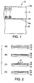
- a circular polarization controlling optical element 10 includes, as shown in Fig. 1, a glass substrate 12, and a cholesteric liquid crystal layer 14 having a cholesteric order (cholesteric regularity) in planar alignment, supported by the glass substrate 12.
- a cholesteric liquid crystal layer 14 having a cholesteric order (cholesteric regularity) in planar alignment, supported by the glass substrate 12.
- an alignment film 16 having an aligning power for aligning liquid crystalline molecules contained in the cholesteric liquid crystal layer 14.
- the cholesteric liquid crystal layer 14 includes chiral nematic liquid crystal (cholesteric liquid crystal) composed of nematic liquid crystal (liquid crystalline molecules) and a chiral agent, and the helical pitch in the helical structure of the liquid crystalline molecules can be controlled by changing the concentration of the chiral agent.
- the cholesteric liquid crystal layer 14 can be formed in the following manner: after adding a photopolymerization initiator to a cholesteric liquid crystalline monomer solution (cholesteric liquid crystal solution) prepared by mixing the nematic liquid crystal and the chiral agent, the resulting mixture is applied to the alignment film 16 on the glass substrate 12, and cured by the application of ultraviolet light.
- Polymerizable liquid crystalline monomer or oligomer molecules can be used as the liquid crystalline molecules in the liquid crystal layer 14.
- Examples of polymerizable liquid crystalline monomer molecules useful herein include those mixtures of liquid crystalline monomers and chiral compounds that are described in Japanese Patent Laid-Open Publication No. 258638/1995 and Published Japanese Translation No. 508882/1998 of PCT International Publication.
- Examples of polymerizable liquid crystalline oligomer molecules useful herein include the cyclic organopolysiloxane compounds having cholesteric phases as described in Japanese Patent Laid-Open Publication No. 165480/1982.
- the concentration of the chiral agent is linearly changed in the direction of thickness of the cholesteric liquid crystal layer 14. This makes the helical pitch in the helical structure of the liquid crystalline molecules continuously vary in the direction of thickness of the cholesteric liquid crystal layer 14.
- the helical pitch on the first main surface 14a side may be shorter (see Fig. 1) or longer than that on the second main surface 14b side, opposite to the first main surface 14a side.
- a variation of helical pitch is determined by the difference in reactivity between the nematic liquid crystal (main component of the cholesteric liquid crystal) and the chiral agent. If the reactivity of the chiral agent is higher than that of the main component, the helical pitch on the glass substrate 12 side becomes shorter, and, in the reverse case, it becomes longer.
- the cholesteric liquid crystal layer 14 as described above has the property of selecting polarized light (the property of splitting polarized light), that is, the property of separating a component polarized in one direction from a component polarized in the opposite direction, according to the physical arrangement of the liquid crystalline molecules in the liquid crystal layer.
- polarized light the property of splitting polarized light
- natural light that has entered along the helical axis of the planar arrangement of the liquid crystal (helical center axis) is split into two circularly polarized components, that is, right- and left-handed polarized components; and one of them is transmitted, and the other one is reflected.
- This phenomenon is known as circular dichroism. If the direction of optical rotation in the helical structure of the liquid crystalline molecules is properly selected, the component circularly polarized in the same direction as this is selectively reflected.
- ⁇ 0 nav ⁇ p
- p a helical pitch in the helical structure of liquid crystalline molecules (a length per pitch in the helix of liquid crystalline molecules)
- nav a mean refractive index on a plane perpendicular to the helical axis.
- the half width of the reflection wave range of cholesteric liquid crystal in the visible light range is from 25 to 100 nm, so that the liquid crystal cannot broadly reflect light in the entire visible light range.
- the half width is only 50 nm or less, and the reflection wave range is thus very narrow.
- the helical pitch in the helical structure of the liquid crystalline molecules in the cholesteric liquid crystal layer 14 continuously varies in the direction of thickness of the cholesteric liquid crystal layer 14, so that the optical element can have a remarkably broadened reflection wave range.
- a glass substrate 12 on which an alignment film 16 having an aligning power for aligning liquid crystalline molecules is formed is firstly prepared.
- a cholesteric liquid crystalline monomer solution (cholesteric liquid crystal solution) 13 prepared by mixing nematic liquid crystal and a chiral agent is applied by means of a spinner or the like.
- a photopolymerization initiator is added beforehand to this cholesteric liquid crystal solution 13.
- Any of conventional photopolymerization initiators for example, Irg 907, Irg 184, Irg 361 or Irg 651 (manufactured by Ciba Corp.) may be herein used.
- the cholesteric liquid crystal solution 13 applied is heated by a hot plate or the like at a temperature between 50°C and 90°C to evaporate the solvent contained in the cholesteric liquid crystal solution 13, thereby forming a cholesteric liquid crystal layer 18 in the uncured state.
- Fig. 2(C) ultraviolet light with a low intensity is applied to the uncured cholesteric liquid crystal layer 18 in the air (in an atmosphere of air).
- the photopolymerization initiator contained in the cholesteric liquid crystal solution and the ultraviolet light applied from the outside initiate polymerization.
- the liquid crystalline molecules in the uncured cholesteric liquid crystal layer 18 are three-dimensionally crosslinked (polymerized), and a cured cholesteric liquid crystal layer 14 as shown in Fig. 2(D) is finally obtained.
- the glass substrate 12 on which the uncured cholesteric liquid crystal layer 18 is formed may be heated, if necessary.
- three-dimensional cross-linkage is herein meant that polymerizable monomer or oligomer molecules are three-dimensionally polymerized so that the resulting polymer can have a network structure.
- the non-glass-substrate-side surface of the uncured cholesteric liquid crystal layer 18 formed on the alignment film 16 on the glass substrate 12 is exposed to air, radical polymerization that is caused by the application of ultraviolet light is hindered due to oxygen contained in the air (oxygen concentration: approx. 20%). Therefore, the liquid crystalline molecules on the non-glass-substrate-side surface of the uncured cholesteric liquid crystal layer 18 are not so easily cured as those molecules that are on the glass-substrate-side surface of the same.
- the liquid crystalline molecules in the uncured cholesteric liquid crystal layer 18 are not cured at the same rate; and thus, distribution of the rate of curing is provided in the uncured cholesteric liquid crystal layer 18.
- This distribution of the concentration of the liquid crystalline components makes the helical pitch in the helical structure of the liquid crystalline molecules in the cured cholesteric liquid crystal layer 14 linearly vary in the direction of thickness of the liquid crystal layer.
- the cured cholesteric liquid crystal layer 14 can thus have a broadened reflection wave range.
- the variation of helical pitch in the helical structure of the liquid crystalline molecules in the cholesteric liquid crystal layer 14 is determined, as mentioned previously, by the difference in reactivity between the nematic liquid crystal (main component of the cholesteric liquid crystal) and the chiral agent. For instance, in the case where the reactivity of the main component is lower than that of the chiral agent, the helical pitch on the glass substrate 12 side becomes shorter, and, in the reverse case, it becomes longer.
- the intensity of ultraviolet light to be applied is preferably from about 10% to about 1%, more preferably from about 8% to about 2% of that of ultraviolet light required to cure, in the above-described atmosphere of air, the liquid crystalline molecules contained in the uncured cholesteric liquid crystal layer 18 while keeping the helical pitch uniform.
- the cholesteric liquid crystal layer according to the embodiment of the present invention does not contain non-crosslinkable materials that are usually used to provide a distribution of the concentration of liquid crystal components, it is possible to fully cure the layer, even if the layer comes into the above situation, by applying ultraviolet light with a proper intensity after a distribution of the concentration of the liquid crystal component is provided in the cholesteric liquid crystal layer.
- the helical structure characteristic of the cholesteric liquid crystal layer according to the embodiment of the invention has already been fixed in the aforementioned process of production, so that the optical properties of the cholesteric liquid crystal layer do not change even when ultraviolet light is additionally applied to the layer as described above.
- the helical pitch in the helical structure of the liquid crystalline molecules aligned in planar alignment in the cholesteric liquid crystal layer 14 are controlled by linearly changing the chiral agent concentration in the direction of thickness of the cholesteric liquid crystal layer 14. It is therefore possible to attain the broadening of reflection wave range by using a single liquid crystal layer without laminating a plurality of liquid crystal layers. Moreover, the deterioration of optical properties by interfacial reflection can also be avoided because the optical interfaces are present only in a decreased number.
- the resulting cholesteric liquid crystal layer shows heat resistance, and has optical properties that have been fixed and that will not change even when heated.
- the step of curing the uncured cholesteric liquid crystal layer 18 it is not necessary to heat the layer to high temperatures (150 to 300°C) at which annealing is usually conducted, so that it becomes possible to select liquid crystalline materials from a wider range of materials.
- a circular polarization controlling optical element 10 in the method of producing a circular polarization controlling optical element 10 according to the embodiment of the present invention, it is possible to make the transition from a cholesteric phase in which the helical pitch is intrinsically uniform throughout a liquid crystal layer to such a cholesteric phase in which the helical pitch continuously varies in a liquid crystal layer, by curing the uncured cholesteric liquid crystal layer 18 so that the degree of curing on one surface of the cured cholesteric liquid crystal layer will be different from that on the other surface of the same. It is therefore possible to simply and efficiently produce a circular polarization controlling optical element 10 including a single cholesteric liquid crystal layer 14, having a broadened reflection wave range, and to well control the width of the reflection wave range of the cholesteric liquid crystal layer 14.
- the non-glass-substrate-side surface of the cholesteric liquid crystal layer 18 is exposed to air while ultraviolet light is being applied to the uncured cholesteric liquid crystal layer 18.
- the atmosphere in which ultraviolet light is applied is not limited to air, and any gaseous atmosphere can be used as long as its oxygen concentration at normal pressures is 10% or more.
- the present invention is not limited to this, and any other constitution may be adopted as long as it can fulfill such a condition that oxygen does not exist on one surface of the uncured cholesteric liquid crystal layer 18 but that only the other surface of the layer is exposed to air (an atmosphere containing oxygen).
- a cholesteric liquid crystal solution 13 is firstly applied to an alignment layer 16 on a glass substrate (first substrate) 12 as shown in Fig. 3(A).
- the solvent contained in the cholesteric liquid crystal solution 13 is then evaporated by heat treatment carried out in order to form an uncured cholesteric liquid crystal layer 18 as shown in Fig. 3(B).
- Fig. 3(A) a cholesteric liquid crystal solution 13 is firstly applied to an alignment layer 16 on a glass substrate (first substrate) 12 as shown in Fig. 3(A).
- the solvent contained in the cholesteric liquid crystal solution 13 is then evaporated by heat treatment carried out in order to form an uncured cholesteric liquid crystal layer 18 as shown in Fig. 3(B).
- an additional substrate (second substrate) 20 made from an oxygen-permeable material is brought into close contact with the non-glass-substrate-side surface of the uncured cholesteric liquid crystal layer 18, and then, ultraviolet light is applied to the uncured cholesteric liquid crystal layer 18 sandwiched between the glass substrate 12 (the alignment film 16) and the additional substrate 20 (the alignment film 22). As a result, a cured cholesteric liquid crystal layer 14 is finally obtained as shown in Fig. 3(D). While applying ultraviolet light to the uncured cholesteric liquid crystal layer 18, it is preferable to supply oxygen to the non-glass-substrate-side surface of the uncured cholesteric liquid crystal layer 18 through the additional substrate 20.
- oxygen-permeable resins, etc. useful for contact lenses, oxygen-permeable membranes or the like may be used.
- the concentration or partial pressure of oxygen is kept constant while ultraviolet light is being applied to the uncured cholesteric liquid crystal layer 18.
- the present invention is not limited to this, and the step of applying ultraviolet light may be effected in such a manner that the concentration of oxygen is made high at the beginning of the application of ultraviolet light and gradually decreased thereafter. If ultraviolet light is applied in this manner, the rate of curing of the liquid crystal can be controlled by the rate of decrease of the oxygen concentration.
- a circular polarization controlling optical element 10 is made with a cholesteric liquid crystal layer 14, a single layer, only.
- the present invention is not limited to this, and a plurality of cholesteric liquid crystal layers 14 may be laminated to obtain a circular polarization controlling optical element having a desired reflection wave range (e.g., the entire visible light range).
- a 35% toluene solution of a cholesteric liquid crystalline monomer (cholesteric liquid crystal solution) was prepared by mixing nematic liquid crystal and a chiral agent.
- a photopolymerization initiator was added in an amount of 5% of the cholesteric liquid crystal.
- Irg 907 (manufactured by Ciba Corp.) was used as the photopolymerization initiator.
- the above-prepared cholesteric liquid crystal solution was applied to a glass substrate that had been provided with a polyimide film having an aligning power, and then dried at a temperature of 90°C to remove the solvent (toluene) in the solution, whereby a 3- ⁇ m thick cholesteric liquid crystal layer in the uncured state was formed.
- the cholesteric liquid crystal layer thus formed was cholesteric in a wide temperature range from normal temperatures to 100°C, had a reflection wave range centered at a wavelength of 535 nm, having a half width of 46 nm, and specularly reflected greenish right-handed polarized light.
- This uncured cholesteric liquid crystal layer was placed in the air together with the glass substrate, and 2.6 mW/cm 2 of ultraviolet light (310 nm) was applied to the layer at a temperature of 90°C for 60 seconds.
- a cured cholesteric liquid crystal layer having a broadened reflection wave range whose half width was approximately 150 nm was finally obtained.
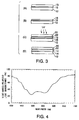
- Fig. 4 The dependence, on wavelength, of the right-handed circularly polarized light transmittance of the above cholesteric liquid crystal layer is shown in Fig. 4. Further, the change in helical pitch p in the helical structure of this cholesteric liquid crystal layer is shown in Fig. 5.
- Example 2 In the same manner as in Example 1, an uncured cholesteric liquid crystal layer was formed on a glass substrate that had been provided with a polyimide film having an aligning power. 7.5 mW/cm 2 of ultraviolet light (310 nm) was then applied to this uncured cholesteric liquid crystal layer in the air at a temperature of 90°C for 20 seconds. Thus, a cured cholesteric liquid crystal layer having a broadened reflection wave range whose half width was approximately 100 nm was finally obtained.
- Uncured cholesteric liquid crystal layers formed in the same manner as in Example 1 were cured under various conditions (the atmosphere and the intensity of ultraviolet light applied), and the optical properties of the cured cholesteric liquid crystal layers were compared.
- Figs. 7 to 10 are graphs showing the dependence, on wavelength, of the right-handed circularly polarized light transmittance of the cholesteric liquid crystal layers cured under the conditions shown in Table 1. Atmosphere in Which Curing Is Conducted intensity of UV Applied (mW/cm 2 ) Half width of Reflection Spectrum (nm) Nitrogen (oxygen concentration not more than 0.2%) 220 43 100 43 50 43 10 43 1 43 Air 220 43 150 43 100 43 90 43 75 62 50 62 25 (peak split) 7.5 100 3.5 110 2.5 150
- the half width of the reflection wave range remains equal to the conventional one as shown in Table 1 and Fig. 8, and the broadening of reflection wave range does not take place.
- the half width of the reflection wave range is increased as shown in Table 1 and Fig. 9, and the broadening of reflection wave range can thus be attained.
Landscapes
- Physics & Mathematics (AREA)
- General Physics & Mathematics (AREA)
- Optics & Photonics (AREA)
- Chemical & Material Sciences (AREA)
- Crystallography & Structural Chemistry (AREA)
- Polarising Elements (AREA)
- Liquid Crystal (AREA)
Priority Applications (1)
| Application Number | Priority Date | Filing Date | Title |
|---|---|---|---|
| EP06012077A EP1734386A3 (de) | 2001-03-28 | 2002-03-26 | Zirkularpolarisierendes optisches Element und zugehöriges Herstellungsverfahren |
Applications Claiming Priority (2)
| Application Number | Priority Date | Filing Date | Title |
|---|---|---|---|
| JP2001094057A JP3513494B2 (ja) | 2001-03-28 | 2001-03-28 | 円偏光制御光学素子の製造方法 |
| JP2001094057 | 2001-03-28 |
Related Child Applications (1)
| Application Number | Title | Priority Date | Filing Date |
|---|---|---|---|
| EP06012077A Division EP1734386A3 (de) | 2001-03-28 | 2002-03-26 | Zirkularpolarisierendes optisches Element und zugehöriges Herstellungsverfahren |
Publications (3)
| Publication Number | Publication Date |
|---|---|
| EP1245970A2 true EP1245970A2 (de) | 2002-10-02 |
| EP1245970A3 EP1245970A3 (de) | 2004-01-28 |
| EP1245970B1 EP1245970B1 (de) | 2007-05-16 |
Family
ID=18948308
Family Applications (2)
| Application Number | Title | Priority Date | Filing Date |
|---|---|---|---|
| EP06012077A Ceased EP1734386A3 (de) | 2001-03-28 | 2002-03-26 | Zirkularpolarisierendes optisches Element und zugehöriges Herstellungsverfahren |
| EP02006928A Expired - Lifetime EP1245970B1 (de) | 2001-03-28 | 2002-03-26 | Zirkularpolarisierendes optisches Element und zugehöriges Herstellungsverfahren |
Family Applications Before (1)
| Application Number | Title | Priority Date | Filing Date |
|---|---|---|---|
| EP06012077A Ceased EP1734386A3 (de) | 2001-03-28 | 2002-03-26 | Zirkularpolarisierendes optisches Element und zugehöriges Herstellungsverfahren |
Country Status (7)
| Country | Link |
|---|---|
| US (1) | US6816215B2 (de) |
| EP (2) | EP1734386A3 (de) |
| JP (1) | JP3513494B2 (de) |
| KR (1) | KR100849552B1 (de) |
| CN (1) | CN1183393C (de) |
| DE (1) | DE60220116T2 (de) |
| TW (1) | TW584767B (de) |
Families Citing this family (21)
| Publication number | Priority date | Publication date | Assignee | Title |
|---|---|---|---|---|
| KR100772669B1 (ko) * | 2001-04-04 | 2007-11-02 | 다이니폰 인사츠 가부시키가이샤 | 원편광 추출 광학 소자의 제조 방법과, 원편광 추출 광학소자 및, 이를 구비한 편광 광원 장치 및 액정 표시 장치 |
| JP2003149439A (ja) * | 2001-11-12 | 2003-05-21 | Dainippon Printing Co Ltd | 円偏光制御光学素子の製造方法 |
| JP4293888B2 (ja) * | 2003-03-31 | 2009-07-08 | 日東電工株式会社 | 広帯域コレステリック液晶フィルムの製造方法、円偏光板、直線偏光素子、照明装置および液晶表示装置 |
| JP4293882B2 (ja) * | 2003-03-31 | 2009-07-08 | 日東電工株式会社 | 広帯域コレステリック液晶フィルムの製造方法、円偏光板、直線偏光素子、照明装置および液晶表示装置 |
| JP4233379B2 (ja) * | 2003-05-02 | 2009-03-04 | 日東電工株式会社 | コレステリック液晶フィルム、その製造方法および円偏光反射フィルム、二波長域反射型反射フィルム |
| US7527836B2 (en) * | 2004-12-28 | 2009-05-05 | Dai Nippon Printing Co., Ltd. | Optical element and method for manufacturing the same |
| JP5000179B2 (ja) * | 2005-04-07 | 2012-08-15 | メルク パテント ゲゼルシャフト ミット ベシュレンクテル ハフツング | 配向膜 |
| JP2007065314A (ja) * | 2005-08-31 | 2007-03-15 | Nippon Zeon Co Ltd | 円偏光分離シート |
| CN101354459B (zh) * | 2008-09-22 | 2011-04-20 | 北京科技大学 | 可反射圆偏振光及非偏振光的液晶薄膜材料的制备方法 |
| US20100226006A1 (en) * | 2009-03-04 | 2010-09-09 | American Polarizers, Inc. | Acrylic circular polarization 3d lens and method of producing same |
| JP5259501B2 (ja) * | 2009-06-11 | 2013-08-07 | 富士フイルム株式会社 | 赤外光反射板、赤外光反射性合わせガラス、並びにコレステリック液晶層を有する積層体及び合わせガラス |
| CN103221851B (zh) * | 2010-11-10 | 2016-06-15 | Lg化学株式会社 | 液晶膜 |
| JP2014089431A (ja) * | 2012-10-04 | 2014-05-15 | Fujifilm Corp | 光学フィルム、偏光板および画像表示装置 |
| CN102981308B (zh) * | 2012-11-30 | 2015-02-18 | 京东方科技集团股份有限公司 | 透明显示器 |
| US10989850B2 (en) | 2013-09-27 | 2021-04-27 | Lg Chem, Ltd. | Optical film having a liquid crystal layer including twisted nematic liquid crystal compounds |
| CN103746284B (zh) * | 2014-01-21 | 2016-08-17 | 东南大学 | 基于温控的偏振方式可调的液晶随机激光器及制造方法 |
| JP2017194672A (ja) * | 2016-04-18 | 2017-10-26 | 日東電工株式会社 | 液晶表示装置 |
| KR20190006890A (ko) * | 2017-07-11 | 2019-01-21 | 경상대학교산학협력단 | 원형 편광 소자, 이를 포함하는 노치 필터 및 밴드 패스 필터 |
| WO2019013466A1 (ko) * | 2017-07-11 | 2019-01-17 | 경상대학교 산학협력단 | 원형 편광 소자, 이를 포함하는 노치 필터 및 밴드 패스 필터 |
| CN118192088A (zh) * | 2019-12-27 | 2024-06-14 | 富士胶片株式会社 | 图像显示装置及ar玻璃 |
| JPWO2025018426A1 (de) * | 2023-07-20 | 2025-01-23 |
Citations (6)
| Publication number | Priority date | Publication date | Assignee | Title |
|---|---|---|---|---|
| JPS56165480A (en) | 1980-05-26 | 1981-12-19 | Oki Electric Ind Co Ltd | Originating connection system for entrusted public telephone circuit of coin throw-in type |
| JPH06281814A (ja) | 1993-01-11 | 1994-10-07 | Philips Electron Nv | コレステリック偏光子及びその製造方法 |
| JPH07258638A (ja) | 1994-02-23 | 1995-10-09 | Merck Patent Gmbh | 液晶状物質 |
| US5691789A (en) | 1995-10-30 | 1997-11-25 | Li; Le | Single-layer reflective super broadband circular polarizer and method of fabrication therefor |
| JPH10319235A (ja) | 1997-05-16 | 1998-12-04 | Nitto Denko Corp | 偏光素子、照明装置及び液晶表示装置 |
| JPH1144816A (ja) | 1997-05-29 | 1999-02-16 | Nitto Denko Corp | 円偏光分離板、その製造方法、光学素子、偏光光源装置及び液晶表示装置 |
Family Cites Families (16)
| Publication number | Priority date | Publication date | Assignee | Title |
|---|---|---|---|---|
| DE3110048A1 (de) | 1981-03-16 | 1982-09-30 | Consortium für elektrochemische Industrie GmbH, 8000 München | "fluessigkristalline phasen aufweisende zusammensetzungen auf basis cyclischer organopolysiloxane, ihre herstellung und deren verwendung" |
| EP0154953B1 (de) * | 1984-03-12 | 1991-01-30 | Matsushita Electric Industrial Co., Ltd. | Optischer Filter und Verfahren zur Herstellung |
| FR2572813A1 (fr) * | 1984-11-07 | 1986-05-09 | Armstrong World Ind Inc | Procede pour preparer des revetements liquides polymeres presentant des reponses optiques multiples et revetements ainsi obtenus |
| US5061046A (en) * | 1989-12-19 | 1991-10-29 | The University Of Rochester | Gradient index liquid crystal devices and method of fabrication thereof |
| US6034753A (en) * | 1991-11-27 | 2000-03-07 | Reveo, Inc. | Circularly polarizing reflective material having super broad-band reflection and transmission characteristics and method of fabricating and using same in diverse applications |
| DE69409977T2 (de) * | 1993-01-11 | 1998-10-22 | Koninkl Philips Electronics Nv | Beleuchtungssystem und ein solches System umfassendes Anzeigegerät |
| DE4441651A1 (de) | 1994-11-23 | 1996-04-25 | Basf Ag | Verfahren zur oberflächlichen Beschichtung von Substraten |
| JPH1112556A (ja) * | 1997-06-27 | 1999-01-19 | Shin Etsu Chem Co Ltd | 紫外線硬化型シリコーン剥離性組成物 |
| DE19843724A1 (de) * | 1997-10-08 | 1999-04-15 | Basf Ag | Polymerisierbare chirale Verbindungen und deren Verwendung |
| JP3580124B2 (ja) * | 1998-03-05 | 2004-10-20 | 日東電工株式会社 | 光学素子、照明装置及び液晶表示装置 |
| EP0982605A1 (de) * | 1998-08-26 | 2000-03-01 | MERCK PATENT GmbH | Reflektierender Film |
| TW394852B (en) * | 1998-08-26 | 2000-06-21 | Merck Patent Gmbh | Reflective film |
| KR100427568B1 (ko) * | 1999-04-09 | 2004-04-30 | 주식회사 엘지화학 | 원편광자 및 그의 제조 방법 |
| KR100675997B1 (ko) * | 1999-07-02 | 2007-01-29 | 메르크 파텐트 게엠베하 | 다층 콜레스테릭 필름의 제조 방법 |
| US6714276B2 (en) * | 2000-02-08 | 2004-03-30 | Sharp Kabushiki Kaisha | Liquid crystal display device |
| US6917399B2 (en) * | 2001-02-22 | 2005-07-12 | 3M Innovative Properties Company | Optical bodies containing cholesteric liquid crystal material and methods of manufacture |
-
2001
- 2001-03-28 JP JP2001094057A patent/JP3513494B2/ja not_active Expired - Fee Related
-
2002
- 2002-03-26 EP EP06012077A patent/EP1734386A3/de not_active Ceased
- 2002-03-26 DE DE60220116T patent/DE60220116T2/de not_active Expired - Lifetime
- 2002-03-26 KR KR1020020016391A patent/KR100849552B1/ko not_active Expired - Fee Related
- 2002-03-26 EP EP02006928A patent/EP1245970B1/de not_active Expired - Lifetime
- 2002-03-27 TW TW091106040A patent/TW584767B/zh not_active IP Right Cessation
- 2002-03-28 CN CNB021402000A patent/CN1183393C/zh not_active Expired - Fee Related
- 2002-03-28 US US10/107,445 patent/US6816215B2/en not_active Expired - Lifetime
Patent Citations (6)
| Publication number | Priority date | Publication date | Assignee | Title |
|---|---|---|---|---|
| JPS56165480A (en) | 1980-05-26 | 1981-12-19 | Oki Electric Ind Co Ltd | Originating connection system for entrusted public telephone circuit of coin throw-in type |
| JPH06281814A (ja) | 1993-01-11 | 1994-10-07 | Philips Electron Nv | コレステリック偏光子及びその製造方法 |
| JPH07258638A (ja) | 1994-02-23 | 1995-10-09 | Merck Patent Gmbh | 液晶状物質 |
| US5691789A (en) | 1995-10-30 | 1997-11-25 | Li; Le | Single-layer reflective super broadband circular polarizer and method of fabrication therefor |
| JPH10319235A (ja) | 1997-05-16 | 1998-12-04 | Nitto Denko Corp | 偏光素子、照明装置及び液晶表示装置 |
| JPH1144816A (ja) | 1997-05-29 | 1999-02-16 | Nitto Denko Corp | 円偏光分離板、その製造方法、光学素子、偏光光源装置及び液晶表示装置 |
Also Published As
| Publication number | Publication date |
|---|---|
| EP1245970A3 (de) | 2004-01-28 |
| JP3513494B2 (ja) | 2004-03-31 |
| DE60220116D1 (de) | 2007-06-28 |
| CN1387055A (zh) | 2002-12-25 |
| TW584767B (en) | 2004-04-21 |
| EP1734386A2 (de) | 2006-12-20 |
| DE60220116T2 (de) | 2007-09-13 |
| US20020167627A1 (en) | 2002-11-14 |
| JP2002286935A (ja) | 2002-10-03 |
| EP1245970B1 (de) | 2007-05-16 |
| EP1734386A3 (de) | 2007-01-03 |
| KR20020077102A (ko) | 2002-10-11 |
| CN1183393C (zh) | 2005-01-05 |
| KR100849552B1 (ko) | 2008-07-31 |
| US6816215B2 (en) | 2004-11-09 |
Similar Documents
| Publication | Publication Date | Title |
|---|---|---|
| US6816215B2 (en) | Circular polarization controlling optical element and method of producing the same | |
| US5948831A (en) | Method for manufacturing a broadband cholesteric polarizer | |
| JP3745221B2 (ja) | 円偏光抽出光学素子及びその製造方法、偏光光源装置、液晶表示装置 | |
| US6862073B2 (en) | Circularly-polarized-light extracting optical element and process of producing the same | |
| US7352422B2 (en) | Retardation optical element and method of producing the same, and polarization element and liquid crystal display, each including retardation optical element | |
| JP2005049866A (ja) | 位相差層およびそれを用いた液晶表示装置 | |
| US6803985B2 (en) | Process for producing optical element, optical element, optical films using optical element, and illuminator and liquid crystal display each using optical element or optical films | |
| JP2003517623A (ja) | 配列させた組織の物品の製作方法およびその適用 | |
| US7075598B2 (en) | Circularly polarizing element having multiple low reflectance cholesteric liquid crystal layers and process for producing the same | |
| KR100772669B1 (ko) | 원편광 추출 광학 소자의 제조 방법과, 원편광 추출 광학소자 및, 이를 구비한 편광 광원 장치 및 액정 표시 장치 | |
| JP3728212B2 (ja) | 円偏光抽出光学素子、偏光光源装置及び液晶表示装置 | |
| US7057687B2 (en) | Method of patterning cholesteric film using a laser and optical element having the cholesteric film patterned by the method | |
| EP0838699A1 (de) | Phasenverzögerungsfolie bestehend aus einer durch schräges Aufdampfen hergestellten anorganischen dielektrischen Schicht mit positiver Brechungsindexanisotropie | |
| JP2004145268A (ja) | 位相差光学素子及びその製造方法、並びに位相差光学素子を備えた偏光素子及び液晶表示装置 | |
| CN114761861B (zh) | 导光元件及图像显示装置 | |
| JP2003240943A (ja) | 円偏光素子およびその製造方法 | |
| WO2025183175A1 (ja) | 導光素子、および、ar表示デバイス | |
| HK1008570A (en) | Phase retarder film comprising an oblique evaporated layer of an inorganic dielectric having a positive refractive index anisotropy | |
| JP2004326131A (ja) | 円偏光抽出光学素子及びその製造方法、偏光光源装置、液晶表示装置 |
Legal Events
| Date | Code | Title | Description |
|---|---|---|---|
| PUAI | Public reference made under article 153(3) epc to a published international application that has entered the european phase |
Free format text: ORIGINAL CODE: 0009012 |
|
| AK | Designated contracting states |
Kind code of ref document: A2 Designated state(s): AT BE CH CY DE DK ES FI FR GB GR IE IT LI LU MC NL PT SE TR |
|
| AX | Request for extension of the european patent |
Free format text: AL;LT;LV;MK;RO;SI |
|
| PUAL | Search report despatched |
Free format text: ORIGINAL CODE: 0009013 |
|
| AK | Designated contracting states |
Kind code of ref document: A3 Designated state(s): AT BE CH CY DE DK ES FI FR GB GR IE IT LI LU MC NL PT SE TR |
|
| AX | Request for extension of the european patent |
Extension state: AL LT LV MK RO SI |
|
| RIC1 | Information provided on ipc code assigned before grant |
Ipc: 7G 02B 5/30 A Ipc: 7C 09K 19/38 B Ipc: 7C 09K 19/58 B |
|
| 17P | Request for examination filed |
Effective date: 20040325 |
|
| AKX | Designation fees paid |
Designated state(s): DE FR GB NL |
|
| 17Q | First examination report despatched |
Effective date: 20040916 |
|
| GRAP | Despatch of communication of intention to grant a patent |
Free format text: ORIGINAL CODE: EPIDOSNIGR1 |
|
| GRAS | Grant fee paid |
Free format text: ORIGINAL CODE: EPIDOSNIGR3 |
|
| GRAA | (expected) grant |
Free format text: ORIGINAL CODE: 0009210 |
|
| AK | Designated contracting states |
Kind code of ref document: B1 Designated state(s): DE FR GB NL |
|
| REG | Reference to a national code |
Ref country code: GB Ref legal event code: FG4D |
|
| REF | Corresponds to: |
Ref document number: 60220116 Country of ref document: DE Date of ref document: 20070628 Kind code of ref document: P |
|
| ET | Fr: translation filed | ||
| PLBE | No opposition filed within time limit |
Free format text: ORIGINAL CODE: 0009261 |
|
| STAA | Information on the status of an ep patent application or granted ep patent |
Free format text: STATUS: NO OPPOSITION FILED WITHIN TIME LIMIT |
|
| 26N | No opposition filed |
Effective date: 20080219 |
|
| PGFP | Annual fee paid to national office [announced via postgrant information from national office to epo] |
Ref country code: NL Payment date: 20110218 Year of fee payment: 10 |
|
| PGFP | Annual fee paid to national office [announced via postgrant information from national office to epo] |
Ref country code: GB Payment date: 20120326 Year of fee payment: 11 |
|
| PGFP | Annual fee paid to national office [announced via postgrant information from national office to epo] |
Ref country code: DE Payment date: 20120424 Year of fee payment: 11 |
|
| PGFP | Annual fee paid to national office [announced via postgrant information from national office to epo] |
Ref country code: FR Payment date: 20120416 Year of fee payment: 11 |
|
| REG | Reference to a national code |
Ref country code: NL Ref legal event code: V1 Effective date: 20121001 |
|
| PG25 | Lapsed in a contracting state [announced via postgrant information from national office to epo] |
Ref country code: NL Free format text: LAPSE BECAUSE OF NON-PAYMENT OF DUE FEES Effective date: 20121001 |
|
| GBPC | Gb: european patent ceased through non-payment of renewal fee |
Effective date: 20130326 |
|
| REG | Reference to a national code |
Ref country code: FR Ref legal event code: ST Effective date: 20131129 |
|
| REG | Reference to a national code |
Ref country code: DE Ref legal event code: R119 Ref document number: 60220116 Country of ref document: DE Effective date: 20131001 |
|
| PG25 | Lapsed in a contracting state [announced via postgrant information from national office to epo] |
Ref country code: FR Free format text: LAPSE BECAUSE OF NON-PAYMENT OF DUE FEES Effective date: 20130402 Ref country code: GB Free format text: LAPSE BECAUSE OF NON-PAYMENT OF DUE FEES Effective date: 20130326 Ref country code: DE Free format text: LAPSE BECAUSE OF NON-PAYMENT OF DUE FEES Effective date: 20131001 |