EP1244170A2 - Aufladbare Lithium Zelle und Verbindungsstruktur dafür - Google Patents
Aufladbare Lithium Zelle und Verbindungsstruktur dafür Download PDFInfo
- Publication number
- EP1244170A2 EP1244170A2 EP20020005913 EP02005913A EP1244170A2 EP 1244170 A2 EP1244170 A2 EP 1244170A2 EP 20020005913 EP20020005913 EP 20020005913 EP 02005913 A EP02005913 A EP 02005913A EP 1244170 A2 EP1244170 A2 EP 1244170A2
- Authority
- EP
- European Patent Office
- Prior art keywords
- lithium secondary
- secondary cell
- cell
- electrode body
- inner electrode
- Prior art date
- Legal status (The legal status is an assumption and is not a legal conclusion. Google has not performed a legal analysis and makes no representation as to the accuracy of the status listed.)
- Granted
Links
Images


Classifications
-
- H—ELECTRICITY
- H01—ELECTRIC ELEMENTS
- H01M—PROCESSES OR MEANS, e.g. BATTERIES, FOR THE DIRECT CONVERSION OF CHEMICAL ENERGY INTO ELECTRICAL ENERGY
- H01M10/00—Secondary cells; Manufacture thereof
- H01M10/05—Accumulators with non-aqueous electrolyte
- H01M10/052—Li-accumulators
-
- H—ELECTRICITY
- H01—ELECTRIC ELEMENTS
- H01M—PROCESSES OR MEANS, e.g. BATTERIES, FOR THE DIRECT CONVERSION OF CHEMICAL ENERGY INTO ELECTRICAL ENERGY
- H01M10/00—Secondary cells; Manufacture thereof
- H01M10/60—Heating or cooling; Temperature control
- H01M10/61—Types of temperature control
- H01M10/613—Cooling or keeping cold
-
- H—ELECTRICITY
- H01—ELECTRIC ELEMENTS
- H01M—PROCESSES OR MEANS, e.g. BATTERIES, FOR THE DIRECT CONVERSION OF CHEMICAL ENERGY INTO ELECTRICAL ENERGY
- H01M10/00—Secondary cells; Manufacture thereof
- H01M10/60—Heating or cooling; Temperature control
- H01M10/64—Heating or cooling; Temperature control characterised by the shape of the cells
- H01M10/643—Cylindrical cells
-
- H—ELECTRICITY
- H01—ELECTRIC ELEMENTS
- H01M—PROCESSES OR MEANS, e.g. BATTERIES, FOR THE DIRECT CONVERSION OF CHEMICAL ENERGY INTO ELECTRICAL ENERGY
- H01M10/00—Secondary cells; Manufacture thereof
- H01M10/60—Heating or cooling; Temperature control
- H01M10/65—Means for temperature control structurally associated with the cells
- H01M10/651—Means for temperature control structurally associated with the cells characterised by parameters specified by a numeric value or mathematical formula, e.g. ratios, sizes or concentrations
-
- H—ELECTRICITY
- H01—ELECTRIC ELEMENTS
- H01M—PROCESSES OR MEANS, e.g. BATTERIES, FOR THE DIRECT CONVERSION OF CHEMICAL ENERGY INTO ELECTRICAL ENERGY
- H01M50/00—Constructional details or processes of manufacture of the non-active parts of electrochemical cells other than fuel cells, e.g. hybrid cells
- H01M50/50—Current conducting connections for cells or batteries
- H01M50/543—Terminals
- H01M50/547—Terminals characterised by the disposition of the terminals on the cells
- H01M50/548—Terminals characterised by the disposition of the terminals on the cells on opposite sides of the cell
-
- H—ELECTRICITY
- H01—ELECTRIC ELEMENTS
- H01M—PROCESSES OR MEANS, e.g. BATTERIES, FOR THE DIRECT CONVERSION OF CHEMICAL ENERGY INTO ELECTRICAL ENERGY
- H01M50/00—Constructional details or processes of manufacture of the non-active parts of electrochemical cells other than fuel cells, e.g. hybrid cells
- H01M50/50—Current conducting connections for cells or batteries
- H01M50/543—Terminals
- H01M50/547—Terminals characterised by the disposition of the terminals on the cells
- H01M50/55—Terminals characterised by the disposition of the terminals on the cells on the same side of the cell
-
- H—ELECTRICITY
- H01—ELECTRIC ELEMENTS
- H01M—PROCESSES OR MEANS, e.g. BATTERIES, FOR THE DIRECT CONVERSION OF CHEMICAL ENERGY INTO ELECTRICAL ENERGY
- H01M50/00—Constructional details or processes of manufacture of the non-active parts of electrochemical cells other than fuel cells, e.g. hybrid cells
- H01M50/50—Current conducting connections for cells or batteries
- H01M50/543—Terminals
- H01M50/552—Terminals characterised by their shape
- H01M50/553—Terminals adapted for prismatic, pouch or rectangular cells
-
- H—ELECTRICITY
- H01—ELECTRIC ELEMENTS
- H01M—PROCESSES OR MEANS, e.g. BATTERIES, FOR THE DIRECT CONVERSION OF CHEMICAL ENERGY INTO ELECTRICAL ENERGY
- H01M50/00—Constructional details or processes of manufacture of the non-active parts of electrochemical cells other than fuel cells, e.g. hybrid cells
- H01M50/50—Current conducting connections for cells or batteries
- H01M50/543—Terminals
- H01M50/552—Terminals characterised by their shape
- H01M50/559—Terminals adapted for cells having curved cross-section, e.g. round, elliptic or button cells
-
- H—ELECTRICITY
- H01—ELECTRIC ELEMENTS
- H01M—PROCESSES OR MEANS, e.g. BATTERIES, FOR THE DIRECT CONVERSION OF CHEMICAL ENERGY INTO ELECTRICAL ENERGY
- H01M10/00—Secondary cells; Manufacture thereof
- H01M10/05—Accumulators with non-aqueous electrolyte
- H01M10/052—Li-accumulators
- H01M10/0525—Rocking-chair batteries, i.e. batteries with lithium insertion or intercalation in both electrodes; Lithium-ion batteries
-
- H—ELECTRICITY
- H01—ELECTRIC ELEMENTS
- H01M—PROCESSES OR MEANS, e.g. BATTERIES, FOR THE DIRECT CONVERSION OF CHEMICAL ENERGY INTO ELECTRICAL ENERGY
- H01M10/00—Secondary cells; Manufacture thereof
- H01M10/60—Heating or cooling; Temperature control
- H01M10/62—Heating or cooling; Temperature control specially adapted for specific applications
- H01M10/625—Vehicles
-
- H—ELECTRICITY
- H01—ELECTRIC ELEMENTS
- H01M—PROCESSES OR MEANS, e.g. BATTERIES, FOR THE DIRECT CONVERSION OF CHEMICAL ENERGY INTO ELECTRICAL ENERGY
- H01M10/00—Secondary cells; Manufacture thereof
- H01M10/60—Heating or cooling; Temperature control
- H01M10/65—Means for temperature control structurally associated with the cells
- H01M10/655—Solid structures for heat exchange or heat conduction
- H01M10/6551—Surfaces specially adapted for heat dissipation or radiation, e.g. fins or coatings
-
- H—ELECTRICITY
- H01—ELECTRIC ELEMENTS
- H01M—PROCESSES OR MEANS, e.g. BATTERIES, FOR THE DIRECT CONVERSION OF CHEMICAL ENERGY INTO ELECTRICAL ENERGY
- H01M10/00—Secondary cells; Manufacture thereof
- H01M10/60—Heating or cooling; Temperature control
- H01M10/65—Means for temperature control structurally associated with the cells
- H01M10/656—Means for temperature control structurally associated with the cells characterised by the type of heat-exchange fluid
- H01M10/6561—Gases
-
- H—ELECTRICITY
- H01—ELECTRIC ELEMENTS
- H01M—PROCESSES OR MEANS, e.g. BATTERIES, FOR THE DIRECT CONVERSION OF CHEMICAL ENERGY INTO ELECTRICAL ENERGY
- H01M10/00—Secondary cells; Manufacture thereof
- H01M10/60—Heating or cooling; Temperature control
- H01M10/65—Means for temperature control structurally associated with the cells
- H01M10/656—Means for temperature control structurally associated with the cells characterised by the type of heat-exchange fluid
- H01M10/6567—Liquids
-
- H—ELECTRICITY
- H01—ELECTRIC ELEMENTS
- H01M—PROCESSES OR MEANS, e.g. BATTERIES, FOR THE DIRECT CONVERSION OF CHEMICAL ENERGY INTO ELECTRICAL ENERGY
- H01M10/00—Secondary cells; Manufacture thereof
- H01M10/60—Heating or cooling; Temperature control
- H01M10/65—Means for temperature control structurally associated with the cells
- H01M10/657—Means for temperature control structurally associated with the cells by electric or electromagnetic means
- H01M10/6572—Peltier elements or thermoelectric devices
-
- H—ELECTRICITY
- H01—ELECTRIC ELEMENTS
- H01M—PROCESSES OR MEANS, e.g. BATTERIES, FOR THE DIRECT CONVERSION OF CHEMICAL ENERGY INTO ELECTRICAL ENERGY
- H01M50/00—Constructional details or processes of manufacture of the non-active parts of electrochemical cells other than fuel cells, e.g. hybrid cells
- H01M50/50—Current conducting connections for cells or batteries
-
- H—ELECTRICITY
- H01—ELECTRIC ELEMENTS
- H01M—PROCESSES OR MEANS, e.g. BATTERIES, FOR THE DIRECT CONVERSION OF CHEMICAL ENERGY INTO ELECTRICAL ENERGY
- H01M6/00—Primary cells; Manufacture thereof
- H01M6/04—Cells with aqueous electrolyte
- H01M6/06—Dry cells, i.e. cells wherein the electrolyte is rendered non-fluid
- H01M6/10—Dry cells, i.e. cells wherein the electrolyte is rendered non-fluid with wound or folded electrodes
-
- H—ELECTRICITY
- H01—ELECTRIC ELEMENTS
- H01M—PROCESSES OR MEANS, e.g. BATTERIES, FOR THE DIRECT CONVERSION OF CHEMICAL ENERGY INTO ELECTRICAL ENERGY
- H01M6/00—Primary cells; Manufacture thereof
- H01M6/42—Grouping of primary cells into batteries
-
- Y—GENERAL TAGGING OF NEW TECHNOLOGICAL DEVELOPMENTS; GENERAL TAGGING OF CROSS-SECTIONAL TECHNOLOGIES SPANNING OVER SEVERAL SECTIONS OF THE IPC; TECHNICAL SUBJECTS COVERED BY FORMER USPC CROSS-REFERENCE ART COLLECTIONS [XRACs] AND DIGESTS
- Y02—TECHNOLOGIES OR APPLICATIONS FOR MITIGATION OR ADAPTATION AGAINST CLIMATE CHANGE
- Y02E—REDUCTION OF GREENHOUSE GAS [GHG] EMISSIONS, RELATED TO ENERGY GENERATION, TRANSMISSION OR DISTRIBUTION
- Y02E60/00—Enabling technologies; Technologies with a potential or indirect contribution to GHG emissions mitigation
- Y02E60/10—Energy storage using batteries
-
- Y—GENERAL TAGGING OF NEW TECHNOLOGICAL DEVELOPMENTS; GENERAL TAGGING OF CROSS-SECTIONAL TECHNOLOGIES SPANNING OVER SEVERAL SECTIONS OF THE IPC; TECHNICAL SUBJECTS COVERED BY FORMER USPC CROSS-REFERENCE ART COLLECTIONS [XRACs] AND DIGESTS
- Y02—TECHNOLOGIES OR APPLICATIONS FOR MITIGATION OR ADAPTATION AGAINST CLIMATE CHANGE
- Y02P—CLIMATE CHANGE MITIGATION TECHNOLOGIES IN THE PRODUCTION OR PROCESSING OF GOODS
- Y02P70/00—Climate change mitigation technologies in the production process for final industrial or consumer products
- Y02P70/50—Manufacturing or production processes characterised by the final manufactured product
-
- Y—GENERAL TAGGING OF NEW TECHNOLOGICAL DEVELOPMENTS; GENERAL TAGGING OF CROSS-SECTIONAL TECHNOLOGIES SPANNING OVER SEVERAL SECTIONS OF THE IPC; TECHNICAL SUBJECTS COVERED BY FORMER USPC CROSS-REFERENCE ART COLLECTIONS [XRACs] AND DIGESTS
- Y02—TECHNOLOGIES OR APPLICATIONS FOR MITIGATION OR ADAPTATION AGAINST CLIMATE CHANGE
- Y02T—CLIMATE CHANGE MITIGATION TECHNOLOGIES RELATED TO TRANSPORTATION
- Y02T10/00—Road transport of goods or passengers
- Y02T10/60—Other road transportation technologies with climate change mitigation effect
- Y02T10/70—Energy storage systems for electromobility, e.g. batteries
Definitions
- the present invention relates to a lithium secondary cell (hereinafter simply referred to as “cell” ) and a lithium secondary cell connecting structure (hereinafter simply referred to as “connecting structure”), and more particularly, to a lithium secondary cell and a lithium secondary cell connecting structure capable of preventing a lowering of performance due to the use and extending its service life.
- cell a lithium secondary cell
- connecting structure a lithium secondary cell connecting structure capable of preventing a lowering of performance due to the use and extending its service life.
- Lithium secondary cells are widely used as power supplies for portable communication apparatuses and electronic devices such as notebook personal computers in recent years. Furthermore, the development of lithium secondary cells is underway as motor drive batteries for electric vehicles and hybrid electric vehicles (hereinafter simply referred to as "electric vehicle, etc.") in response to a growing international demand for resource saving and energy saving to protect global environment.
- This lithium secondary cell is used for a connecting structure made up of a plurality of cells connected in series to secure a voltage necessary to drive the motor. Since the service life of an electric vehicle, etc. is estimated to be about 5 to 10 years, this lithium secondary cell and the lithium secondary cell connecting structure are expected to have their service life equivalent to that of the electric vehicle, etc.
- This lithium secondary cell has a high operating voltage and high energy density, having an advantage of being able to discharge a high current, while it has a disadvantage of generating great heat, liable to cause a temperature rise of the battery.
- This temperature rise due to heating is attributable to inner resistance of the inner electrode body generated when a current flows.
- the inner electrode body is continuously exposed to a high temperature state caused by the temperature rise, its internal resistance further increases, which causes the inconvenience of eventually reducing the battery capacity and drastically reducing performance.
- the lithium secondary cell connecting structure needs to provide space between cells to facilitate the heat dissipation of each lithium secondary cell, which causes a problem of poor volumetric efficiency of the connecting structure.
- the present invention has been implemented in view of the above-described conventional problems and it is an object of the present invention to provide a lithium secondary cell and a lithium secondary cell connecting structure intended to prevent heating of the lithium secondary cell and the lithium secondary cell connecting structure to maintain their temperature within an appropriate range so as to prevent a lowering of the performance due to the use and extend their service life.
- the present invention provides a lithium secondary cell comprising: an inner electrode body impregnated with a non-aqueous electrolyte, made up of a positive electrode and a negative electrode wound or laminated together with a separator inserted in between, an cell case that contains the inner electrode body and an electrode cover that seals the inner electrode body provided with an cell cover, external terminals and internal terminals characterized by including a means for cooling the electric current path.
- the electric current path includes the external terminals.
- a lithium secondary cell comprising: an inner electrode body impregnated with a non-aqueous electrolyte, made up of a positive electrode and a negative electrode wound so as to surround an outer wall of a core with a separator inserted in between, and a cylindrical cell case that coaxially contains the inner electrode body; wherein a heat conductivity ratio (X/Y) of a heat conductivity (X) in a direction of the center axis to a heat conductivity (Y) in a direction of a diameter of the lithium secondary cell is 50 or more.
- the heat conductivity ratio (X/Y) is 100 or more.
- This configuration condition is ideally applicable to a lithium secondary cell having a capacity of 2 Ah or more and ideally mounted on a vehicle to start an engine and ideally used for an electric vehicle or hybrid electric vehicle.
- the present invention provides a lithium secondary cell connecting structure constructed of a plurality of lithium secondary cells connected in series and/or in parallel by means of a bus bar, with the lithium secondary cell comprising an inner electrode body impregnated with a non-aqueous electrolyte, made up of a positive electrode and a negative electrode wound or laminated together with a separator inserted in between, an cell case that contains the inner electrode body and an electrode cover that seals the inner electrode body provided with an cell cover, external terminals and internal terminals , characterized by including a means for cooling the electric current path.
- the electric current path includes the bus bar.
- This configuration condition is ideally applicable to a lithium secondary cell having a capacity of 2 Ah or more and ideally mounted on a vehicle to start an engine and ideally used for an electric vehicle or hybrid electric vehicle.
- Fig. 1 is a sectional view showing an embodiment of a lithium secondary cell of the present invention.
- Fig. 2 is a schematic top view showing an embodiment of a lithium secondary cell connecting structure of the present invention.
- Fig. 3 is a schematic perspective view showing another embodiment of the lithium secondary cell connecting structure of the present invention.
- Fig. 4 is a perspective view showing an embodiment of a wind type inner electrode body.
- Fig. 5 is a perspective view showing an embodiment of a laminate type inner electrode body.
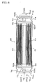
- Fig. 6 is a sectional view showing another embodiment of a lithium secondary cell of the present invention.
- the lithium secondary cell of the present invention comprises an inner electrode body impregnated with a non-aqueous electrolyte, made up of a positive electrode and a negative electrode wound or laminated together with a separator inserted in between, an cell case that contains the inner electrode body and an electrode cover that seals the inner electrode body provided with an cell cover, external terminals and internal terminals, and the lithium secondary cell connecting structure is constructed of a plurality of the above-described lithium secondary cells connected in series and/or in parallel by means of a bus bar.
- the wind type inner electrode body used in the present invention is constructed, as shown in Fig. 4, of a positive electrode 2 and negative electrode 3 (hereinafter referred to as "electrode plates 2 and 3") with a separator 4 made of porous polymers inserted in between to prevent the positive electrode 2 and negative electrode 3 from directly touching each other, wound around the outer wall of a core 13.
- the laminate type inner electrode body used in the present invention is constructed, as shown in Fig. 5, of positive electrodes 8 and negative electrodes 9 each having a predetermined area and shape laminated one atop another with separators 10 inserted in between.
- the materials used and manufacturing method of the positive electrodes 8 and negative electrodes 9 are the same as those of the wind type inner electrode body 1.
- the positive electrode 2 is created by applying a positive electrode active material to both sides of a collector substrate.
- a metal foil such as aluminum foil or titanium foil is used, which has excellent corrosion resistance to positive electrochemical reaction.
- a punching metal or mesh can also be used.
- a lithium transition metal compound oxide such as lithium manganese oxide (LiMn 2 O 4 ) or lithium cobalt oxide (LiCoO 2 ) is preferably used and it is desirable to add carbon micro powder such as acetylene black to these substances as a conductive assistant.
- the negative electrode 3 can be created in the same way as for the positive electrode 2.
- a metal foil such as a copper foil or nickel foil, which has excellent corrosion resistance to negative electrode electrochemical reaction is preferably used.
- an amorphous carbon material such as soft carbon or hard carbon or high graphitized carbon powder such as artificial graphite or natural graphite is preferably used.
- the separator 4 one with a three-layer structure with a Li ion (Li + ) conducting polyethylene film (PE film) with micro pores sandwiched between porous Li ion (Li + ) conducting polypropylene films (PP film) is preferably used.
- Li ion (Li + ) conducting polyethylene film PE film
- PP film porous Li ion conducting polypropylene films
- collector tabs 5 and 6 When the separator 4 is inserted between the electrode plates 2 and 3, a positive electrode collector tab 5 and positive electrode collector tab 6 (hereinafter also referred to as “collector tabs 5 and 6") are attached to the parts of the electrode plates 2 and 3 where no electrode active materials are applied and the collector substrate is exposed.
- collector tabs 5 and 6 foil-like tabs made of the same material used for the electrode plates 2 and 3 are preferably used.
- the wind type electrode body 1 of Fig. 4 a plurality of each of the collector tabs 5 and 6 are shown. Though only one collector tab 5 and one collector tab 6 are required in the wind type electrode body 1, inner resistance of a cell can be reduced by increasing the number of the collector tabs 5 and 6. It is further preferable to attach collector tabs 5 and 6 in a plurality of portions of each of the electrode plates 2 and 3 because of good heat conductivity.
- non-aqueous electrolyte it is preferable to use a single solvent or a mixture solvent of those of the carbonic acid ester system such as ethylene carbonate (EC), diethyl carbonate (DEC), dimethyl carbonate (DMC) and propylene carbonate (PC), or ⁇ -butyrolactone, tetrahydrofuran, acetonitrile, etc.
- EC ethylene carbonate
- DEC diethyl carbonate
- DMC dimethyl carbonate
- PC propylene carbonate
- ⁇ -butyrolactone tetrahydrofuran, acetonitrile, etc.
- lithium complex fluorine compound such as lithium hexafluoro phosphate (LiPF 6 ) or lithium fluoroborate (LiBF 4 ), or lithium halide compound such as lithium perchlorate (LiClO 4 ) is included and one, two or more types of these substances are dissolved into the above-described solvent for use. It is especially desirable to use LiPF 6 which is hardly subject to oxidation or decomposition and shows high lithium ion conductivity in the non-aqueous electrolyte.
- the electrode cover includes cell covers 15A and 15B to cover the cell, inner terminals 17A and 17B to collect current temporarily inside the cell, and external terminals 16A and 16B to extract current to the outside of the cell, and an alloy of aluminum for the positive electrode cover, or copper or nickel or an alloy with either of them for the negative electrode cover is preferably used in view of chemical reaction for each electrode. Any metal can be used without problems as far as its purity is at least 90%.
- a metal pipe is preferably used and aluminum pipe or stainless steel pipe is preferably used. Since a metal material is used as the cell case in this way, it is desirable to insert an insulation polymer film between the inner surface of the cell case and the outer region of the inner electrode body to prevent conduction between the inner electrode body and cell case and conduction between the collector tab and cell case.
- the collector tabs attached at both ends of the inner electrode body are connected to the inner terminals of the electrode cover to create a cell element first and this cell element is inserted into the cell case and hold it in a stable position. Then, the cell element is impregnated with a non-aqueous electrolyte and the electrode cover and the cell case are jointed to seal the inner electrode body.
- the lithium secondary cell connecting structure refers to a plurality of cells connected in series with a positive external terminal of one lithium secondary cell connected with a negative external terminal of another lithium secondary cell.
- a bus bar 26 can be preferably used.
- a metal material with high conductivity and small connection resistance with respect to the external terminal is used and its material is selected from the material of the external terminal. If an aluminum external terminal is used, aluminum is preferably used for the bus bar 26, too, while an external terminal is made of copper, copper is preferably used for the bus bar 26, too.
- a connector made of different types of material such as a clad material (e.g., connector with aluminum and copper).
- a clad material e.g., connector with aluminum and copper.
- the shape of the bus bar 26 it is possible to use a tabular type, a punching metal or mesh. It is preferable to use a bus bar of punching metal or mesh because such a bus bar has a large surface area, thereby improving the cooling efficiency of the bus bar.
- this connecting structure 27 it is possible to accommodate cells 18 by piling one atop another in vertical direction or connecting one after another in horizontal direction with the cells 18 fixed with an appropriate frame, and thus accommodate multiple cells 18 compactly.
- lithium ions moving through the inner electrode body causes a current to flow and temperature to rise in the cell, which further accelerates the movement of lithium ions and allows the current to flow more easily.
- a current flows more easily in the high temperature area than other areas and in this way currents are concentrated on the high temperature area, which further heats up the high temperature area, which causes more currents to concentrate on the high temperature area, producing a vicious cycle in this way.
- the capacity of the lithium secondary cell reduces and its performance also deteriorates.
- Fig. 1 shows the lithium secondary cell 18 having a wind type inner electrode body 1.
- This lithium secondary cell 18 houses the inner electrode body 1 in an aluminum or stainless steel cell case 14 with both ends of the cell case 14 sealed with aluminum electrode covers or aluminum or copper electrode covers.
- the wind type inner electrode body is constructed of a wind body wound around the outer wall of an aluminum core 13, comprising an aluminum positive electrode 2 and a copper or nickel negative electrode 3 to which an electrode active material is applied, with a resin separator 4 inserted between the positive and negative electrodes and a plurality of aluminum positive electrode collector tabs 5 and a plurality of copper or nickel negative electrode collector tabs 6 to deliver current to the outside connected at both ends of the wind body.
- the collector tabs 5 and 6 of the positive electrode and negative electrode of this inner electrode body 1 are connected to their respective electrode covers by welding or other method.
- heat produced inside this lithium secondary cell is dissipated from the surface of the cell through the electric current path.
- the heat transfer path in this case is the same as the electric current path constructed of the members such as the positive electrode, negative electrode, positive electrode collector tab, negative electrode collector tab, internal terminals and external terminals. Since all of these members are made of metal, the heat transfer path has a structure that facilitates heat transfer in the direction of the center axis of the cell.
- heat produced inside must traverse the wind body of the inner electrode body to be dissipated from the surface of the cell to the outside.
- the heat transfer path in this case includes areas with lower heat conductivity than metallic parts such as the laminated structure of the positive electrode and negative electrode, electrode active material, electrolyte and separator, and has a structure that suppresses heat transfer compared to the center axis direction.
- the result of a calculation performed by the present inventor et al. using the lithium secondary cell 18 in Fig. 1 shows that heat conductivity inside the cell is 34.0 W/m ⁇ K in the center axis direction of the cell while it is 0.30 W/m ⁇ K in the diameter direction of the cell, resulting in a heat conductivity ratio (center axis direction/diameter direction of the cell) of 113.
- the lithium secondary cell of the present invention is constructed in such a way as to include a means for cooling the electric current path. It is preferable that the aforementioned electric current path to be cooled includes an external terminal. More specifically, as shown in Fig. 1, it is preferable that the lithium secondary cell is provided with the aforementioned cooling means in such a manner that the cooling means 28 cools the external terminals 16A and 16B.
- This structure makes it possible to effectively remove the heat produced inside the lithium secondary cell through the heat transfer path, that is, the electric current path in the center axis direction of the cell having high heat conductivity.
- the present invention can prevent a lowering of performance and extend the service life of the lithium secondary cell.
- a lithium secondary cell is preferably provided with an inner electrode body (wind type inner electrode body 61) impregnated with a non-aqueous electrolyte, made up of a positive electrode and a negative electrode each made of at least one metallic foil 60 and wound or laminated, a positive electrode collector member 62A and a negative electrode collector member 62B for drawing out a current from the wind type inner electrode body 61, and structured to draw out a current from the wind type inner electrode body 61 by connecting an edge of the aforementioned metallic foil 60 to a predetermined portion of the positive electrode collector member 62A and/or a negative electrode collector member 62B, and further structured to connect an edge (joint edge) disposed to be connected with a predetermined portion of a positive electrode collector member 62A and/or a negative electrode collector member 62B among an edge of the metallic foil 60 with the predetermined portion of the positive electrode collector member 62A and/or a negative electrode corrector member 62B
- a lithium secondary cell of the present invention is preferable because it has a short heat transmission path, is excellent in cooling efficiency, and is superior in volume efficiency to a lithium secondary cell having a structure using a collector tab since an edge face of each of metallic foils constituting a positive electrode plate and a negative electrode plate is directly connected with an electricity collector member without using collector tabs 5, 6 shown in Fig. 1 to collect electricity from a plurality of portions of the electrode plates.
- a laser welding or the like is suitably adopted for connecting an edge of the aforementioned metallic foil with a predetermined portion of the both electrode collector members.
- Fig. 6 shows a state where a positive electrode collector member 62A is connected with a positive inner terminal 69A, and a negative electrode collector member 62B is connected with a negative electrode inner terminal 69B by means of an electrode lead member 72; they may be connected directly with each other.
- the cooling means is not limited to a particular type, but can be any means if it can at least cool the external terminals of the lithium secondary cell appropriately.
- a means includes an adequately cooled gas or liquid or a cooling apparatus using electricity or gas, etc. as the energy source, and more particularly an air blower or an apparatus with cooling fins provided so as to cool mainly the electric current path, that is, the external terminals.
- a cooling apparatus using electricity as an energy source is exemplified by a Peltier element.
- a lithium secondary cell comprising: an inner electrode body impregnated with a non-aqueous electrolyte, made up of a positive electrode and a negative electrode wound so as to surround an outer wall of a core with a separator inserted in between, and a cylindrical cell case that coaxially contains said inner electrode body; wherein a heat conductivity ratio (X/Y) of a heat conductivity (X) in a direction of the center axis to a heat conductivity (Y) in a direction of a diameter of said lithium secondary cell is 50 or more.
- X/Y heat conductivity ratio
- the aforementioned heat conductivities in a direction of the center axis and in a direction of a diameter are synthetic heat conductivities calculated, with respect to each direction, from values of a heat conductivity and a thickness (length) of each member constituting the lithium secondary cell.
- a heat conductivity of each member depends on quality of materials, porosities, etc., and greatly influenced particularly by heat conductivities of a positive active material and a negative active material quality of materials and porosities of members constituting the positive active material and the negative active material.
- a synthetic heat conductivity depends on a thickness (length) of the members, a heat conductivity sometimes differs even if the same kind of material is used.
- a lithium secondary cell provided with a wind type inner electrode body has a longer heat transmission path in a direction of the center axis in comparison with a heat transmission path in a direction of a diameter.
- the length of heat transmission path in the direction of a center axis is about several to ten times longer than that in the direction of a diameter.
- a lithium secondary cell of the present invention is characterized in that a lowering of performance can be prevented to give a long service life by suppressing generation of heat with its excellent cooling efficiency because a heat conductivity ratio (X/Y) of a heat conductivity (X) in a direction of the center axis to a heat conductivity (Y) in a direction of a diameter of said lithium secondary cell is 50 or more, that is, a heat conductivity (X) in a direction of the center axis is sufficiently high in comparison with a heat conductivity (Y) in a direction of a diameter of said lithium secondary cell.
- the cell is provided with, for example, a cooling means to cool an electric current path because heat inside the cell is emitted more effectively.
- the heat conductivity ratio (X/Y) of a heat conductivity (X) in a direction of the center axis to a heat conductivity (Y) in a direction of a diameter is 100 or more in view of enhancing cooling effect.
- the configuration condition of the lithium secondary cell of the present invention is also preferably used for a cell having a capacity of 2 Ah or more. It goes without saying that the application of the cell is not limited to a particular field. This cell can be used ideally to start an engine and, above all, to drive the motor of an electric vehicle or hybrid electric vehicle in particular as a car-mounted large capacity cell requiring the ability to prevent a lowering of performance for a long period of time.
- the lithium secondary cell connecting structure of the present invention is constructed in such a way as to include a means for cooling the electric current path.
- the electric current path to be cooled preferably includes a bus bar. More specifically, as shown in Fig. 2 and Fig. 3, it is preferable that the lithium secondary cell connecting structure is constructed in such a manner that the cooling means 28 cools the bus bar 26.
- This structure makes it possible to effectively remove heat produced inside the lithium secondary cell through the heat transfer path in the center axis direction of the cell, that is, the electric current path.
- the present invention can prevent a lowering of performance and extend the service life of the lithium secondary cell connecting structure.
- the cooling means is not limited to a particular means, but can be any means if it can at least cool the bus bar adequately. More specifically, the cooling means similar to the one for the lithium secondary cell can be used.
- the lithium secondary cell of the present invention includes a means for cooling the electric current path of the lithium secondary cell and the lithium secondary cell connecting structure of the present invention includes a means for cooling the electric current path of the lithium secondary cell connecting structure.
- connection body 27 using the laminate type electrode body as shown in Fig. 3 can implement the connection body 27 with no gaps between the cells 18.
- the configuration condition of the lithium secondary cell connection body of the present invention can also be ideally used for a connecting structure with a cell capacity of 2 Ah or more. It goes without saying that the application of the lithium secondary cell connection body is not limited to a particular field. This cell can be used ideally to start an engine and, above all, to drive the motor of an electric vehicle or hybrid electric vehicle in particular as the connection body of car-mounted large capacity cells requiring the ability to prevent a lowering of performance for a long period of time.
- the lithium secondary cell and the lithium secondary cell connection body of the present invention prevent heating of the lithium secondary cells and the lithium secondary cell connection body, maintains the temperature within an appropriate range, and can thereby prevent a lowering of performance and extend the service life.
- the present invention provides a lithium secondary cell including an inner electrode body impregnated with a non-aqueous electrolyte, made up of a positive electrode and a negative electrode wound or laminated together with a separator inserted in between, an cell case that contains the inner electrode body and an electrode cover that seals the inner electrode body provided with cell covers, external terminals and internal terminals.
- the lithium secondary cell is provided with a unit for cooling the electric current path.
- the lithium secondary cell is capable of preventing a lowering of performance and extending the service life by preventing heating of the lithium secondary cell and maintaining temperature within an adequate range.
Applications Claiming Priority (4)
| Application Number | Priority Date | Filing Date | Title |
|---|---|---|---|
| JP2001080635 | 2001-03-21 | ||
| JP2001080635 | 2001-03-21 | ||
| JP2002061485A JP4204237B2 (ja) | 2001-03-21 | 2002-03-07 | リチウム二次単電池およびリチウム二次単電池の接続構造体 |
| JP2002061485 | 2002-03-07 |
Publications (3)
| Publication Number | Publication Date |
|---|---|
| EP1244170A2 true EP1244170A2 (de) | 2002-09-25 |
| EP1244170A3 EP1244170A3 (de) | 2004-05-06 |
| EP1244170B1 EP1244170B1 (de) | 2007-01-03 |
Family
ID=26611667
Family Applications (1)
| Application Number | Title | Priority Date | Filing Date |
|---|---|---|---|
| EP20020005913 Expired - Lifetime EP1244170B1 (de) | 2001-03-21 | 2002-03-14 | Aufladbare Lithium Zelle und Verbindungsstruktur dafür |
Country Status (5)
| Country | Link |
|---|---|
| US (1) | US6767666B2 (de) |
| EP (1) | EP1244170B1 (de) |
| JP (1) | JP4204237B2 (de) |
| CA (1) | CA2376904A1 (de) |
| DE (1) | DE60217210T2 (de) |
Cited By (2)
| Publication number | Priority date | Publication date | Assignee | Title |
|---|---|---|---|---|
| EP2375474A1 (de) * | 2010-03-30 | 2011-10-12 | SB LiMotive Co., Ltd. | Sekundärbatterie und Sekundärbatteriemodul |
| US8956753B2 (en) | 2010-03-30 | 2015-02-17 | Samsung Sdi Co., Ltd. | Secondary battery and secondary battery module |
Families Citing this family (36)
| Publication number | Priority date | Publication date | Assignee | Title |
|---|---|---|---|---|
| US6838661B2 (en) * | 2002-03-08 | 2005-01-04 | Lexmark International, Inc. | Torsion oscillator stabilization including maintaining the amplitude of the oscillator without changing its drive frequency |
| KR100727201B1 (ko) * | 2003-07-31 | 2007-06-13 | 닛본 덴끼 가부시끼가이샤 | 리튬 이온 2차 전지 |
| EP2352185A1 (de) * | 2003-10-28 | 2011-08-03 | Johnson Controls Techonology Company | Batterieummantelung mit verbesserter Wärmeverteilung |
| CN1681146A (zh) * | 2004-03-29 | 2005-10-12 | 三星Sdi株式会社 | 电极封装及使用该电极封装的二次电池 |
| US7743614B2 (en) | 2005-04-08 | 2010-06-29 | Bsst Llc | Thermoelectric-based heating and cooling system |
| US8546009B2 (en) * | 2006-01-25 | 2013-10-01 | Tulsee Satish Doshi | Method and apparatus for thermal energy transfer |
| US20100155018A1 (en) | 2008-12-19 | 2010-06-24 | Lakhi Nandlal Goenka | Hvac system for a hybrid vehicle |
| US8568915B2 (en) | 2006-08-11 | 2013-10-29 | Johnson Controls—SAFT Power Solutions LLC | Battery with integrally formed terminal |
| US11660971B2 (en) | 2006-11-07 | 2023-05-30 | Clarios Advanced Solutions Llc | System for arranging and coupling battery cells in a battery module |
| JP5369382B2 (ja) * | 2007-03-19 | 2013-12-18 | 株式会社デンソー | 組電池装置 |
| DE102007063181B4 (de) * | 2007-08-06 | 2010-12-30 | Daimler Ag | Einzelzelle für eine Batterie sowie Verfahren zu deren Herstellung |
| DE102007063184B4 (de) * | 2007-08-06 | 2011-01-05 | Daimler Ag | Einzelzelle für eine Batterie zur elektrischen Kontaktierung |
| JP4386131B2 (ja) * | 2007-12-05 | 2009-12-16 | 三菱自動車工業株式会社 | 電気自動車 |
| CN102084517A (zh) | 2008-05-15 | 2011-06-01 | 江森自控帅福得先进能源动力系统有限责任公司 | 电池系统 |
| DE102008002103A1 (de) * | 2008-05-30 | 2009-12-03 | Robert Bosch Gmbh | Vorrichtung zur Temperaturregelung eines Speichers für elektrische Energie |
| CN102165625B (zh) * | 2008-08-14 | 2015-11-25 | 江森自控帅福得先进能源动力系统有限责任公司 | 具有密封的放气室的电池模块 |
| KR20100067464A (ko) * | 2008-12-11 | 2010-06-21 | 삼성에스디아이 주식회사 | 전지 모듈 |
| EP2382679B1 (de) * | 2009-01-23 | 2020-04-22 | Johnson Controls Advanced Power Solutions LLC | Batteriemodul mit elektrochemischen zellen mit integral geformten endstücken |
| KR20130054449A (ko) | 2009-02-02 | 2013-05-24 | 가부시키가이샤 지에스 유아사 | 단자간 접속 도체, 조전지, 및 조전지의 제조 방법 |
| RU2011143856A (ru) | 2009-05-18 | 2013-06-27 | БиЭсЭсТи ЭлЭлСи | Система термоуправления батареей |
| DE102009027178A1 (de) * | 2009-06-25 | 2010-12-30 | SB LiMotive Company Ltd., Suwon | Batterie mit Elektrodenwärmeleiter zur effizienten Temperierung |
| KR101222286B1 (ko) * | 2011-01-13 | 2013-01-15 | 로베르트 보쉬 게엠베하 | 이차전지 |
| DE112012000866A5 (de) | 2011-02-18 | 2013-11-21 | Schott Ag | Durchführung |
| WO2013009759A2 (en) | 2011-07-11 | 2013-01-17 | Amerigon Incorporated | Thermoelectric-based thermal management of electrical devices |
| KR101431717B1 (ko) * | 2012-02-06 | 2014-08-26 | 주식회사 엘지화학 | 신규한 구조의 버스 바 |
| FR2997234B1 (fr) * | 2012-10-22 | 2016-05-06 | Renault Sa | Cellule electrochimique de stockage d'electricite. |
| KR102034337B1 (ko) | 2013-01-14 | 2019-10-18 | 젠썸 인코포레이티드 | 전기 디바이스의 열전 기반 열 관리 |
| WO2014120688A1 (en) | 2013-01-30 | 2014-08-07 | Gentherm Incorporated | Thermoelectric-based thermal management system |
| US9203086B2 (en) * | 2013-05-24 | 2015-12-01 | The Boeing Company | Thermally managed battery assembly |
| CN106030898B (zh) | 2013-10-29 | 2019-04-05 | 詹思姆公司 | 利用热电学的电池热管理 |
| KR102226353B1 (ko) | 2014-09-12 | 2021-03-10 | 젠썸 인코포레이티드 | 흑연 열전기적 및/또는 저항성 열 관리 시스템 및 방법 |
| WO2016099614A1 (en) | 2014-12-15 | 2016-06-23 | Gyrus Acmi, Inc. (D/B/A/ Olympus Surgical Technologies America) | Improved control of a basket retrieval device |
| CN107403969B (zh) * | 2016-05-20 | 2019-08-06 | 莫列斯有限公司 | 电池装置及电池连接模块 |
| JP7209475B2 (ja) * | 2018-04-09 | 2023-01-20 | 日産自動車株式会社 | 電池の製造方法 |
| US11152557B2 (en) | 2019-02-20 | 2021-10-19 | Gentherm Incorporated | Thermoelectric module with integrated printed circuit board |
| WO2022074709A1 (ja) * | 2020-10-05 | 2022-04-14 | 株式会社堤水素研究所 | 捲回電池 |
Citations (2)
| Publication number | Priority date | Publication date | Assignee | Title |
|---|---|---|---|---|
| EP0620610A1 (de) * | 1993-04-15 | 1994-10-19 | Sony Corporation | Durchlochte Batterie |
| EP0727833A1 (de) * | 1995-02-17 | 1996-08-21 | Japan Storage Battery Company Limited | Zylindrische Zelle, Zellenpackung und Zellenhalter |
Family Cites Families (5)
| Publication number | Priority date | Publication date | Assignee | Title |
|---|---|---|---|---|
| JP3311402B2 (ja) * | 1992-11-19 | 2002-08-05 | 三洋電機株式会社 | 二次電池 |
| JP3524237B2 (ja) * | 1995-09-27 | 2004-05-10 | ソニー株式会社 | 電気自動車のバッテリ構造 |
| JP3210593B2 (ja) * | 1997-02-17 | 2001-09-17 | 日本碍子株式会社 | リチウム二次電池 |
| US6010800A (en) * | 1998-06-17 | 2000-01-04 | Hughes Electronics Corporation | Method and apparatus for transferring heat generated by a battery |
| JP2000090976A (ja) | 1998-09-11 | 2000-03-31 | Ngk Insulators Ltd | リチウム二次電池モジュール |
-
2002
- 2002-03-07 JP JP2002061485A patent/JP4204237B2/ja not_active Expired - Fee Related
- 2002-03-12 US US10/095,783 patent/US6767666B2/en not_active Expired - Lifetime
- 2002-03-14 EP EP20020005913 patent/EP1244170B1/de not_active Expired - Lifetime
- 2002-03-14 DE DE2002617210 patent/DE60217210T2/de not_active Expired - Lifetime
- 2002-03-14 CA CA002376904A patent/CA2376904A1/en not_active Abandoned
Patent Citations (2)
| Publication number | Priority date | Publication date | Assignee | Title |
|---|---|---|---|---|
| EP0620610A1 (de) * | 1993-04-15 | 1994-10-19 | Sony Corporation | Durchlochte Batterie |
| EP0727833A1 (de) * | 1995-02-17 | 1996-08-21 | Japan Storage Battery Company Limited | Zylindrische Zelle, Zellenpackung und Zellenhalter |
Cited By (2)
| Publication number | Priority date | Publication date | Assignee | Title |
|---|---|---|---|---|
| EP2375474A1 (de) * | 2010-03-30 | 2011-10-12 | SB LiMotive Co., Ltd. | Sekundärbatterie und Sekundärbatteriemodul |
| US8956753B2 (en) | 2010-03-30 | 2015-02-17 | Samsung Sdi Co., Ltd. | Secondary battery and secondary battery module |
Also Published As
| Publication number | Publication date |
|---|---|
| EP1244170B1 (de) | 2007-01-03 |
| US6767666B2 (en) | 2004-07-27 |
| CA2376904A1 (en) | 2002-09-21 |
| JP2002352863A (ja) | 2002-12-06 |
| DE60217210T2 (de) | 2007-10-18 |
| DE60217210D1 (de) | 2007-02-15 |
| EP1244170A3 (de) | 2004-05-06 |
| JP4204237B2 (ja) | 2009-01-07 |
| US20020136944A1 (en) | 2002-09-26 |
Similar Documents
| Publication | Publication Date | Title |
|---|---|---|
| EP1244170B1 (de) | Aufladbare Lithium Zelle und Verbindungsstruktur dafür | |
| JP4173674B2 (ja) | 電気化学デバイスモジュール | |
| CN101682006B (zh) | 单元电池及电源 | |
| US20130177787A1 (en) | Current collector and nonaqueous secondary battery | |
| US8187739B2 (en) | Power storage apparatus and cooling system | |
| JP2005071784A (ja) | 冷却用タブを有するバイポーラ電池 | |
| WO2008023244A2 (en) | Electrode for electric storage device and electric storage device | |
| US9343731B2 (en) | Battery comprising a liquid inlet for electrolyte injection | |
| CN112670601A (zh) | 具有均匀热分布的超高功率混合型电池设计 | |
| US10686182B2 (en) | Secondary battery | |
| JPH11126585A (ja) | 組電池およびそれを用いた電気装置 | |
| JP5989405B2 (ja) | 電源装置 | |
| KR20160055097A (ko) | 비수 전해액 2차 전지 | |
| JP4053802B2 (ja) | 電気化学デバイス | |
| JP2004178914A (ja) | バイポーラ電極およびその電極を用いたバイポーラ二次電池 | |
| JP2000090976A (ja) | リチウム二次電池モジュール | |
| JP2009110936A (ja) | リチウムイオン二次電池 | |
| JP2000260474A (ja) | リチウム2次電池 | |
| JP2003007346A (ja) | リチウム二次電池及びその製造方法 | |
| US9017850B2 (en) | Secondary battery | |
| JP2011086483A (ja) | ラミネート型2次電池 | |
| JP2004171954A (ja) | ラミネート二次電池、複数のラミネート二次電池からなる組電池モジュール、複数の組電池モジュールからなる組電池ならびにこれらいずれかの電池を搭載した電気自動車 | |
| JP5604806B2 (ja) | 金属二次電池 | |
| JP6536908B2 (ja) | リチウムイオン二次電池 | |
| KR20160087141A (ko) | 방열을 촉진하기 위한 개구부를 포함하는 전지셀 카트리지 및 이를 포함하는 전지모듈 |
Legal Events
| Date | Code | Title | Description |
|---|---|---|---|
| PUAI | Public reference made under article 153(3) epc to a published international application that has entered the european phase |
Free format text: ORIGINAL CODE: 0009012 |
|
| AK | Designated contracting states |
Kind code of ref document: A2 Designated state(s): AT BE CH CY DE DK ES FI FR GB GR IE IT LI LU MC NL PT SE TR |
|
| AX | Request for extension of the european patent |
Free format text: AL;LT;LV;MK;RO;SI |
|
| PUAL | Search report despatched |
Free format text: ORIGINAL CODE: 0009013 |
|
| AK | Designated contracting states |
Kind code of ref document: A3 Designated state(s): AT BE CH CY DE DK ES FI FR GB GR IE IT LI LU MC NL PT SE TR |
|
| AX | Request for extension of the european patent |
Extension state: AL LT LV MK RO SI |
|
| 17P | Request for examination filed |
Effective date: 20040427 |
|
| 17Q | First examination report despatched |
Effective date: 20040609 |
|
| AKX | Designation fees paid |
Designated state(s): AT BE CH CY DE DK ES FI FR GB GR IE IT LI LU MC NL PT SE TR |
|
| GRAP | Despatch of communication of intention to grant a patent |
Free format text: ORIGINAL CODE: EPIDOSNIGR1 |
|
| GRAS | Grant fee paid |
Free format text: ORIGINAL CODE: EPIDOSNIGR3 |
|
| GRAA | (expected) grant |
Free format text: ORIGINAL CODE: 0009210 |
|
| AK | Designated contracting states |
Kind code of ref document: B1 Designated state(s): BE CH DE FR GB IT LI SE |
|
| PG25 | Lapsed in a contracting state [announced via postgrant information from national office to epo] |
Ref country code: CH Free format text: LAPSE BECAUSE OF FAILURE TO SUBMIT A TRANSLATION OF THE DESCRIPTION OR TO PAY THE FEE WITHIN THE PRESCRIBED TIME-LIMIT Effective date: 20070103 Ref country code: LI Free format text: LAPSE BECAUSE OF FAILURE TO SUBMIT A TRANSLATION OF THE DESCRIPTION OR TO PAY THE FEE WITHIN THE PRESCRIBED TIME-LIMIT Effective date: 20070103 |
|
| REG | Reference to a national code |
Ref country code: GB Ref legal event code: FG4D |
|
| REF | Corresponds to: |
Ref document number: 60217210 Country of ref document: DE Date of ref document: 20070215 Kind code of ref document: P |
|
| PG25 | Lapsed in a contracting state [announced via postgrant information from national office to epo] |
Ref country code: SE Free format text: LAPSE BECAUSE OF FAILURE TO SUBMIT A TRANSLATION OF THE DESCRIPTION OR TO PAY THE FEE WITHIN THE PRESCRIBED TIME-LIMIT Effective date: 20070403 |
|
| ET | Fr: translation filed | ||
| REG | Reference to a national code |
Ref country code: CH Ref legal event code: PL |
|
| PLBE | No opposition filed within time limit |
Free format text: ORIGINAL CODE: 0009261 |
|
| STAA | Information on the status of an ep patent application or granted ep patent |
Free format text: STATUS: NO OPPOSITION FILED WITHIN TIME LIMIT |
|
| 26N | No opposition filed |
Effective date: 20071005 |
|
| PG25 | Lapsed in a contracting state [announced via postgrant information from national office to epo] |
Ref country code: BE Free format text: LAPSE BECAUSE OF FAILURE TO SUBMIT A TRANSLATION OF THE DESCRIPTION OR TO PAY THE FEE WITHIN THE PRESCRIBED TIME-LIMIT Effective date: 20070103 |
|
| PG25 | Lapsed in a contracting state [announced via postgrant information from national office to epo] |
Ref country code: IT Free format text: LAPSE BECAUSE OF FAILURE TO SUBMIT A TRANSLATION OF THE DESCRIPTION OR TO PAY THE FEE WITHIN THE PRESCRIBED TIME-LIMIT Effective date: 20070103 |
|
| PGFP | Annual fee paid to national office [announced via postgrant information from national office to epo] |
Ref country code: GB Payment date: 20120227 Year of fee payment: 11 |
|
| GBPC | Gb: european patent ceased through non-payment of renewal fee |
Effective date: 20130314 |
|
| PG25 | Lapsed in a contracting state [announced via postgrant information from national office to epo] |
Ref country code: GB Free format text: LAPSE BECAUSE OF NON-PAYMENT OF DUE FEES Effective date: 20130314 |
|
| REG | Reference to a national code |
Ref country code: FR Ref legal event code: PLFP Year of fee payment: 15 |
|
| REG | Reference to a national code |
Ref country code: FR Ref legal event code: PLFP Year of fee payment: 16 |
|
| PGFP | Annual fee paid to national office [announced via postgrant information from national office to epo] |
Ref country code: FR Payment date: 20170213 Year of fee payment: 16 |
|
| PG25 | Lapsed in a contracting state [announced via postgrant information from national office to epo] |
Ref country code: FR Free format text: LAPSE BECAUSE OF NON-PAYMENT OF DUE FEES Effective date: 20180331 |
|
| PGFP | Annual fee paid to national office [announced via postgrant information from national office to epo] |
Ref country code: DE Payment date: 20210302 Year of fee payment: 20 |
|
| REG | Reference to a national code |
Ref country code: DE Ref legal event code: R071 Ref document number: 60217210 Country of ref document: DE |