EP1241404A1 - Lamellenraster - Google Patents
Lamellenraster Download PDFInfo
- Publication number
- EP1241404A1 EP1241404A1 EP02005990A EP02005990A EP1241404A1 EP 1241404 A1 EP1241404 A1 EP 1241404A1 EP 02005990 A EP02005990 A EP 02005990A EP 02005990 A EP02005990 A EP 02005990A EP 1241404 A1 EP1241404 A1 EP 1241404A1
- Authority
- EP
- European Patent Office
- Prior art keywords
- side parts
- grid
- slats
- slots
- lamellae
- Prior art date
- Legal status (The legal status is an assumption and is not a legal conclusion. Google has not performed a legal analysis and makes no representation as to the accuracy of the status listed.)
- Granted
Links
- 241000446313 Lamella Species 0.000 claims abstract description 23
- 239000002184 metal Substances 0.000 claims description 13
- 238000005452 bending Methods 0.000 claims description 9
- 238000004519 manufacturing process Methods 0.000 claims description 3
- 238000004080 punching Methods 0.000 claims description 2
- 238000000034 method Methods 0.000 claims 1
- 230000001419 dependent effect Effects 0.000 description 1
- 238000011161 development Methods 0.000 description 1
- 230000018109 developmental process Effects 0.000 description 1
- 230000004313 glare Effects 0.000 description 1
Images


Classifications
-
- F—MECHANICAL ENGINEERING; LIGHTING; HEATING; WEAPONS; BLASTING
- F21—LIGHTING
- F21V—FUNCTIONAL FEATURES OR DETAILS OF LIGHTING DEVICES OR SYSTEMS THEREOF; STRUCTURAL COMBINATIONS OF LIGHTING DEVICES WITH OTHER ARTICLES, NOT OTHERWISE PROVIDED FOR
- F21V11/00—Screens not covered by groups F21V1/00, F21V3/00, F21V7/00 or F21V9/00
- F21V11/02—Screens not covered by groups F21V1/00, F21V3/00, F21V7/00 or F21V9/00 using parallel laminae or strips, e.g. of Venetian-blind type
-
- F—MECHANICAL ENGINEERING; LIGHTING; HEATING; WEAPONS; BLASTING
- F21—LIGHTING
- F21V—FUNCTIONAL FEATURES OR DETAILS OF LIGHTING DEVICES OR SYSTEMS THEREOF; STRUCTURAL COMBINATIONS OF LIGHTING DEVICES WITH OTHER ARTICLES, NOT OTHERWISE PROVIDED FOR
- F21V17/00—Fastening of component parts of lighting devices, e.g. shades, globes, refractors, reflectors, filters, screens, grids or protective cages
- F21V17/10—Fastening of component parts of lighting devices, e.g. shades, globes, refractors, reflectors, filters, screens, grids or protective cages characterised by specific fastening means or way of fastening
- F21V17/101—Fastening of component parts of lighting devices, e.g. shades, globes, refractors, reflectors, filters, screens, grids or protective cages characterised by specific fastening means or way of fastening permanently, e.g. welding, gluing or riveting
Definitions
- the present invention relates to a lamella grid for an elongated lamp according to the preamble of claim 1.
- elongated lights with fluorescent lamps are in the area of their Light exit opening often provided with louvre grids. These grids are used limit the light emitted downwards to a predetermined exit angle. This avoids that exiting at a too flat exit angle Light leads to glare.
- a grid is, for example, from the DE 91 10 313.4 known.
- a simple embodiment of a lamella grid consists of two elongated ones Side parts and several, arranged perpendicular to the plane of the grid and the slats connecting both side parts.
- Such a lamella grid can consist of one single piece of sheet metal are formed, first punching out a flat sheet metal part and then deformed into the desired structure. First, the deformed both side areas of the sheet metal part to the side parts and then the Slats bent out of the original plane into the desired arrangement or erected. The slats are only connected to the thin connection areas Connected side parts that can easily break when repeated bending. The The stability of such a grid is therefore relatively low. There is also the risk that some slats are accidentally bent out of their parallel arrangement or can be adjusted.
- the present invention is therefore based on the object of ensuring the stability of a to increase such lamella grid.
- This lamella grid for an elongated lamp, which the Features of claim 1 solved.
- This lamella grid according to the invention is characterized in that the side parts each one towards the inside have projecting area in the slots for receiving parts of the Slats are arranged. The slats thus snap into place when erected the side parts, so that bending back is no longer possible. This ensures, on the one hand, that all slats are parallel to one another are arranged, on the other hand, the overall stability of the grid is increased.
- the arrangement according to the invention is particularly suitable for lamella grids which consist of a single sheet metal part are formed. Since bending the slats back is not without is also possible, the load on the connection areas, which the Side parts connecting with the slats, reduced, making breaking practically can be excluded.
- the two side parts preferably have S-shaped profile, the upper and inward area of which the slots for Includes lamella parts.
- the lamellae are preferably essentially rectangular in shape, with the top two corners of the slats in the slots engage.
- separate slats can also be used on the slats Locking projections may be provided.
- the side parts can also at their upper edges Have mounting tabs through which a simple locking of the lamella grid is guaranteed with a lamp holder.
- Lamella grid solved in which first a flat sheet metal part is punched, in one second step the side areas of the sheet metal part into two elongated side parts deformed and then the slats connecting the two side parts into one plane perpendicular to the original plane are bent out, whereby
- the side parts each have an area projecting towards the inside with slots in which slots parts of the slats when bending engage.
- the slats are all bent out at the same time by the both side parts are moved in the longitudinal direction with respect to the slats.
- the lamella grid 1 according to the invention shown in FIGS. 1 to 5 consists of a single, appropriately punched and deformed piece of sheet metal.
- the basic structure the grid 1 is formed by two elongated side parts 2, which is an S-shaped Show profile.
- the two side parts 2 are substantially perpendicular to Grid level arranged, each one in its upper area to the inside have projecting area 3.
- the upper edge of a side part 2 is through an outward fastening tab 5 is formed, which for locking with locking elements or undercuts provided on a lamp holder is provided.
- the grid 1 can easily be seen from the bottom be clamped to a lamp holder.
- a flat sheet metal part is first punched out, which has the structures corresponding to the side parts 2 and the slats 7.
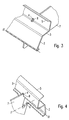
- the side areas of the sheet metal part then become the deformed two elongated side parts 2, with this in particular by the in Fig. 3 shown bending axis II are bent upwards.
- they will Slats 7 bent from the original plane into the vertical position until they with snap their upper corners 8 into the slots 4.
- a simultaneous erection of the Slats 7 is achieved in a simple manner in that the two side parts 2nd can be moved in the longitudinal direction with respect to the slats 7.
- the present invention thus offers a simple solution for producing a Louvre grid, which has a high stability. It can consist of just one Sheet metal part are made, so that the manufacturing costs are extremely low.
Landscapes
- Engineering & Computer Science (AREA)
- General Engineering & Computer Science (AREA)
- Specific Sealing Or Ventilating Devices For Doors And Windows (AREA)
- Non-Portable Lighting Devices Or Systems Thereof (AREA)
- Securing Globes, Refractors, Reflectors Or The Like (AREA)
Abstract
Description
- Fig. 1
- ein Ausführungsbeispiel des erfindungsgemäßen Lamellenrasters in perspektivischer Ansicht von oben;
- Fig. 2
- das in Fig. 1 dargestellte Lamellenraster in perspektivischer Ansicht von unten;
- Fig. 3
- einen Ausschnitt A von Fig. 1 in vergrößerter Darstellung;
- Fig. 4
- einen Ausschnitt B von Fig. 1 in vergrößerter Darstellung; und
- Fig. 5
- einen Ausschnitt C von Fig. 2 in vergrößerter Darstellung.
Claims (9)
- Lamellenraster (1) für eine längliche Leuchte, bestehend aus zwei länglichen Seitenteilen (2) sowie mehreren, senkrecht zur Ebene des Rasters (1) angeordneten und die beiden Seitenteile (2) verbindenden Lamellen (7),
dadurch gekennzeichnet, daß die Seitenteile (2) jeweils einen zur Innenseite hin vorspringenden Bereich (3) aufweisen, in dem Schlitze (4) zur Aufnahme von Teilen (8) der Lamellen (7) angeordnet sind. - Lamellenraster nach Anspruch 1,
dadurch gekennzeichnet, daß dieses durch ein einstückig gestanztes und gebogenes Blechteil gebildet wird. - Lamellenraster nach Anspruch 2,
dadurch gekennzeichnet, daß die Lamellen (7) mit den beiden Seitenteilen (2) einstückig verbunden und in einem Verbindungsbereich (6) um eine Biegeachse (I) in die senkrecht zur Ebene des Rasters (1) angeordnete Stellung verbogen sind. - Lamellenraster nach einem der vorherigen Ansprüche,
dadurch gekennzeichnet, daß die beiden Seitenteile (2) ein S-förmiges Profil aufweisen. - Lamellenraster nach einem der vorherigen Ansprüche,
dadurch gekennzeichnet, daß die Lamellen (7) im wesentlichen rechteckig geformt sind und jeweils mit ihren oberen Ecken (8) in die Schlitze (4) eingreifen. - Lamellenraster nach einem der Ansprüche 1 bis 4,
dadurch gekennzeichnet, daß die Lamellen (7) an ihren Seiten jeweils Rastvorsprünge zum Eingreifen in die Schlitze (4) aufweisen. - Lamellenraster nach einem der vorherigen Ansprüche,
dadurch gekennzeichnet, daß die Seitenteile (2) an ihren oberen Kanten Befestigungslaschen (5) zum Befestigen des Rasters (1) an einer Leuchtenhalterung aufweisen. - Verfahren zum Herstellen eines Lamellenrasters (1) für eine längliche Leuchte mit folgenden Schritten:dadurch gekennzeichnet, daß die Seitenteile (2) jeweils einen zur Innenseite hin vorspringenden Bereich (3) mit Schlitzen (4) aufweisen, in welche Schlitze (4) Teile (8) der Lamellen (7) beim Ausbiegen einrasten.a) Stanzen eines ebenen Blechteils,b) Verformen der Seitenbereiche des Blechteils zu zwei länglichen Seitenteilen (2) undc) Ausbiegen von mehreren, die beiden Seitenteile (2) verbindenden Lamellen (7) in eine senkrecht zur Ursprungsebene angeordnete Ebene,
- Verfahren nach Anspruch 8,
dadurch gekennzeichnet, daß in Schritt c) zum Ausbiegen der Lamellen (7) die beiden Seitenteile (2) gegenüber den Lamellen (7) in Längsrichtung verschoben werden.
Applications Claiming Priority (2)
| Application Number | Priority Date | Filing Date | Title |
|---|---|---|---|
| DE2001112775 DE10112775B4 (de) | 2001-03-16 | 2001-03-16 | Lamellenraster |
| DE10112775 | 2001-03-16 |
Publications (2)
| Publication Number | Publication Date |
|---|---|
| EP1241404A1 true EP1241404A1 (de) | 2002-09-18 |
| EP1241404B1 EP1241404B1 (de) | 2007-11-28 |
Family
ID=7677765
Family Applications (1)
| Application Number | Title | Priority Date | Filing Date |
|---|---|---|---|
| EP20020005990 Expired - Lifetime EP1241404B1 (de) | 2001-03-16 | 2002-03-15 | Lamellenraster |
Country Status (4)
| Country | Link |
|---|---|
| EP (1) | EP1241404B1 (de) |
| DE (2) | DE10112775B4 (de) |
| NO (1) | NO331663B1 (de) |
| PL (1) | PL199879B1 (de) |
Citations (6)
| Publication number | Priority date | Publication date | Assignee | Title |
|---|---|---|---|---|
| DE7441175U (de) * | 1975-06-19 | Licentia Patent Verwaltungs Gmbh | Lamellenraster für Leuchten | |
| DE2916331A1 (de) * | 1979-04-23 | 1980-11-13 | Alfred Korsch | Verfahren zur herstellung eines rasters, insbesondere eines leuchtenblendschutzrasters fuer spiegelrasterleuchten |
| DE3216442A1 (de) * | 1982-05-03 | 1983-11-03 | Jürgen Brickl | Reflektor zur erzeugung von blendfreiheit an langgestreckten leuchten, insbesondere deckenleuchten |
| US4429354A (en) * | 1982-09-29 | 1984-01-31 | Emerson Electric Co. | Lighting fixture louver |
| DE9110313U1 (de) | 1991-08-21 | 1992-03-19 | Zumtobel Licht Gmbh, Dornbirn | Lamelle zur Befestigung eines Domes an einem Lamellenraster einer Leuchte |
| EP0522480A1 (de) * | 1991-07-08 | 1993-01-13 | Ab Fagerhult | Beleuchtungsvorrichtung mit Blendschutzraster und Verfahren zur Herstellung eines solchen Rasters |
-
2001
- 2001-03-16 DE DE2001112775 patent/DE10112775B4/de not_active Expired - Fee Related
-
2002
- 2002-03-13 PL PL352739A patent/PL199879B1/pl unknown
- 2002-03-15 DE DE50211266T patent/DE50211266D1/de not_active Expired - Lifetime
- 2002-03-15 NO NO20021314A patent/NO331663B1/no not_active IP Right Cessation
- 2002-03-15 EP EP20020005990 patent/EP1241404B1/de not_active Expired - Lifetime
Patent Citations (6)
| Publication number | Priority date | Publication date | Assignee | Title |
|---|---|---|---|---|
| DE7441175U (de) * | 1975-06-19 | Licentia Patent Verwaltungs Gmbh | Lamellenraster für Leuchten | |
| DE2916331A1 (de) * | 1979-04-23 | 1980-11-13 | Alfred Korsch | Verfahren zur herstellung eines rasters, insbesondere eines leuchtenblendschutzrasters fuer spiegelrasterleuchten |
| DE3216442A1 (de) * | 1982-05-03 | 1983-11-03 | Jürgen Brickl | Reflektor zur erzeugung von blendfreiheit an langgestreckten leuchten, insbesondere deckenleuchten |
| US4429354A (en) * | 1982-09-29 | 1984-01-31 | Emerson Electric Co. | Lighting fixture louver |
| EP0522480A1 (de) * | 1991-07-08 | 1993-01-13 | Ab Fagerhult | Beleuchtungsvorrichtung mit Blendschutzraster und Verfahren zur Herstellung eines solchen Rasters |
| DE9110313U1 (de) | 1991-08-21 | 1992-03-19 | Zumtobel Licht Gmbh, Dornbirn | Lamelle zur Befestigung eines Domes an einem Lamellenraster einer Leuchte |
Also Published As
| Publication number | Publication date |
|---|---|
| PL199879B1 (pl) | 2008-11-28 |
| NO20021314D0 (no) | 2002-03-15 |
| DE10112775B4 (de) | 2014-12-24 |
| PL352739A1 (en) | 2002-09-23 |
| DE10112775A1 (de) | 2002-09-26 |
| EP1241404B1 (de) | 2007-11-28 |
| DE50211266D1 (de) | 2008-01-10 |
| NO20021314L (no) | 2002-09-17 |
| NO331663B1 (no) | 2012-02-20 |
Similar Documents
| Publication | Publication Date | Title |
|---|---|---|
| DE2655702C3 (de) | Leuchtenraster für eine langgestreckte Lampe | |
| DE69203046T2 (de) | Beleuchtungsvorrichtung mit Blendschutzraster und Verfahren zur Herstellung eines solchen Rasters. | |
| EP1716012A1 (de) | Komponente, insbesondere sonnenblende und insbesondere für ein fahrzeug, verfahren zur herstellung einer komponente | |
| DE3919600A1 (de) | Beleuchtungsanordnung und lampengitter hierfuer | |
| DE3342382C2 (de) | ||
| DE10112775B4 (de) | Lamellenraster | |
| DE202010004995U1 (de) | Befestiger zur Befestigung eines ersten Bauteils an einem zweiten Bauteil | |
| DE3740563A1 (de) | Schiene fuer haengedecken | |
| EP4074934B1 (de) | Steckverbinder und steckverbindung | |
| EP1256758B1 (de) | Leuchtengehäuse | |
| DE3539894A1 (de) | Verkleidung fuer bauwerke | |
| DE3902008C2 (de) | ||
| EP0528198B1 (de) | Lamelle zur Befestigung eines Domes an einem Lamellenraster einer Leuchte | |
| EP1163082A1 (de) | Winkelschleifer | |
| EP0763843A2 (de) | Elektrisches Bauelement, insbesondere relais, und Verfahren zu dessen Einbau in eine Leiterplatte | |
| EP0871271B1 (de) | Montageelement für eine elektrische Anschlussdose | |
| EP1221401A2 (de) | Wischerarme sowie Verfahren zur Herstellung von Wischerarmen | |
| EP0499118A1 (de) | Bausatz kombinierbarer Möbel, insbesondere Schrank- und/oder Regalelemente | |
| DE2946196C2 (de) | Kontaktleiste | |
| AT513711B1 (de) | Reflektor für eine Leuchte, insbesondere für eine Deckeneinbauleuchte | |
| DE29521179U1 (de) | Elektrisches Bauelement, insbesondere Relais, sowie Anordnung eines derartigen Bauelementes mit einer Leiterplatte | |
| EP2251591B1 (de) | Rasterelement für eine Leuchte | |
| DE10318978B4 (de) | Befestigungselement | |
| WO2024194331A1 (de) | Halterahmen für einen steckverbinder | |
| DE19546778C2 (de) | Aufnahmeeinrichtung |
Legal Events
| Date | Code | Title | Description |
|---|---|---|---|
| PUAI | Public reference made under article 153(3) epc to a published international application that has entered the european phase |
Free format text: ORIGINAL CODE: 0009012 |
|
| AK | Designated contracting states |
Kind code of ref document: A1 Designated state(s): AT BE CH CY DE DK ES FI FR GB GR IE IT LI LU MC NL PT SE TR |
|
| AX | Request for extension of the european patent |
Free format text: AL;LT;LV;MK;RO;SI |
|
| RIN1 | Information on inventor provided before grant (corrected) |
Inventor name: SPIEGEL, MICHAEL, ING. Inventor name: RIEDLER, THOMAS, ING. |
|
| 17P | Request for examination filed |
Effective date: 20030130 |
|
| AKX | Designation fees paid |
Designated state(s): AT BE CH CY DE DK ES FI FR GB GR IE IT LI LU MC NL PT SE TR |
|
| 17Q | First examination report despatched |
Effective date: 20061204 |
|
| GRAP | Despatch of communication of intention to grant a patent |
Free format text: ORIGINAL CODE: EPIDOSNIGR1 |
|
| GRAS | Grant fee paid |
Free format text: ORIGINAL CODE: EPIDOSNIGR3 |
|
| GRAA | (expected) grant |
Free format text: ORIGINAL CODE: 0009210 |
|
| RAP1 | Party data changed (applicant data changed or rights of an application transferred) |
Owner name: ZUMTOBEL LIGHTING GMBH |
|
| AK | Designated contracting states |
Kind code of ref document: B1 Designated state(s): AT BE CH CY DE DK ES FI FR GB GR IE IT LI LU MC NL PT SE TR |
|
| REG | Reference to a national code |
Ref country code: IE Ref legal event code: FG4D Free format text: LANGUAGE OF EP DOCUMENT: GERMAN |
|
| REG | Reference to a national code |
Ref country code: CH Ref legal event code: EP |
|
| REF | Corresponds to: |
Ref document number: 50211266 Country of ref document: DE Date of ref document: 20080110 Kind code of ref document: P |
|
| REG | Reference to a national code |
Ref country code: CH Ref legal event code: NV Representative=s name: A. BRAUN, BRAUN, HERITIER, ESCHMANN AG PATENTANWAE |
|
| PG25 | Lapsed in a contracting state [announced via postgrant information from national office to epo] |
Ref country code: SE Free format text: LAPSE BECAUSE OF FAILURE TO SUBMIT A TRANSLATION OF THE DESCRIPTION OR TO PAY THE FEE WITHIN THE PRESCRIBED TIME-LIMIT Effective date: 20080228 Ref country code: ES Free format text: LAPSE BECAUSE OF FAILURE TO SUBMIT A TRANSLATION OF THE DESCRIPTION OR TO PAY THE FEE WITHIN THE PRESCRIBED TIME-LIMIT Effective date: 20080311 |
|
| PG25 | Lapsed in a contracting state [announced via postgrant information from national office to epo] |
Ref country code: FI Free format text: LAPSE BECAUSE OF FAILURE TO SUBMIT A TRANSLATION OF THE DESCRIPTION OR TO PAY THE FEE WITHIN THE PRESCRIBED TIME-LIMIT Effective date: 20071128 |
|
| GBV | Gb: ep patent (uk) treated as always having been void in accordance with gb section 77(7)/1977 [no translation filed] | ||
| REG | Reference to a national code |
Ref country code: CH Ref legal event code: PFA Owner name: ZUMTOBEL LIGHTING GMBH Free format text: ZUMTOBEL LIGHTING GMBH#SCHWEIZER STRASSE 30#6850 DORNBIRN (AT) -TRANSFER TO- ZUMTOBEL LIGHTING GMBH#SCHWEIZER STRASSE 30#6850 DORNBIRN (AT) |
|
| PG25 | Lapsed in a contracting state [announced via postgrant information from national office to epo] |
Ref country code: DK Free format text: LAPSE BECAUSE OF FAILURE TO SUBMIT A TRANSLATION OF THE DESCRIPTION OR TO PAY THE FEE WITHIN THE PRESCRIBED TIME-LIMIT Effective date: 20071128 |
|
| EN | Fr: translation not filed | ||
| BERE | Be: lapsed |
Owner name: ZUMTOBEL LIGHTING GMBH Effective date: 20080331 |
|
| PG25 | Lapsed in a contracting state [announced via postgrant information from national office to epo] |
Ref country code: PT Free format text: LAPSE BECAUSE OF FAILURE TO SUBMIT A TRANSLATION OF THE DESCRIPTION OR TO PAY THE FEE WITHIN THE PRESCRIBED TIME-LIMIT Effective date: 20080428 |
|
| REG | Reference to a national code |
Ref country code: IE Ref legal event code: FD4D |
|
| PLBE | No opposition filed within time limit |
Free format text: ORIGINAL CODE: 0009261 |
|
| STAA | Information on the status of an ep patent application or granted ep patent |
Free format text: STATUS: NO OPPOSITION FILED WITHIN TIME LIMIT |
|
| PG25 | Lapsed in a contracting state [announced via postgrant information from national office to epo] |
Ref country code: FR Free format text: LAPSE BECAUSE OF FAILURE TO SUBMIT A TRANSLATION OF THE DESCRIPTION OR TO PAY THE FEE WITHIN THE PRESCRIBED TIME-LIMIT Effective date: 20080912 Ref country code: IE Free format text: LAPSE BECAUSE OF FAILURE TO SUBMIT A TRANSLATION OF THE DESCRIPTION OR TO PAY THE FEE WITHIN THE PRESCRIBED TIME-LIMIT Effective date: 20071128 Ref country code: MC Free format text: LAPSE BECAUSE OF NON-PAYMENT OF DUE FEES Effective date: 20080331 |
|
| 26N | No opposition filed |
Effective date: 20080829 |
|
| PG25 | Lapsed in a contracting state [announced via postgrant information from national office to epo] |
Ref country code: GB Free format text: LAPSE BECAUSE OF FAILURE TO SUBMIT A TRANSLATION OF THE DESCRIPTION OR TO PAY THE FEE WITHIN THE PRESCRIBED TIME-LIMIT Effective date: 20071128 |
|
| PG25 | Lapsed in a contracting state [announced via postgrant information from national office to epo] |
Ref country code: GR Free format text: LAPSE BECAUSE OF FAILURE TO SUBMIT A TRANSLATION OF THE DESCRIPTION OR TO PAY THE FEE WITHIN THE PRESCRIBED TIME-LIMIT Effective date: 20080229 |
|
| PG25 | Lapsed in a contracting state [announced via postgrant information from national office to epo] |
Ref country code: BE Free format text: LAPSE BECAUSE OF NON-PAYMENT OF DUE FEES Effective date: 20080331 |
|
| PG25 | Lapsed in a contracting state [announced via postgrant information from national office to epo] |
Ref country code: CY Free format text: LAPSE BECAUSE OF FAILURE TO SUBMIT A TRANSLATION OF THE DESCRIPTION OR TO PAY THE FEE WITHIN THE PRESCRIBED TIME-LIMIT Effective date: 20071128 |
|
| PG25 | Lapsed in a contracting state [announced via postgrant information from national office to epo] |
Ref country code: LU Free format text: LAPSE BECAUSE OF NON-PAYMENT OF DUE FEES Effective date: 20080315 |
|
| PG25 | Lapsed in a contracting state [announced via postgrant information from national office to epo] |
Ref country code: TR Free format text: LAPSE BECAUSE OF FAILURE TO SUBMIT A TRANSLATION OF THE DESCRIPTION OR TO PAY THE FEE WITHIN THE PRESCRIBED TIME-LIMIT Effective date: 20071128 |
|
| PG25 | Lapsed in a contracting state [announced via postgrant information from national office to epo] |
Ref country code: IT Free format text: LAPSE BECAUSE OF NON-PAYMENT OF DUE FEES Effective date: 20080331 |
|
| REG | Reference to a national code |
Ref country code: CH Ref legal event code: PCAR Free format text: NEW ADDRESS: HOLBEINSTRASSE 36-38, 4051 BASEL (CH) |
|
| PGFP | Annual fee paid to national office [announced via postgrant information from national office to epo] |
Ref country code: NL Payment date: 20150323 Year of fee payment: 14 |
|
| PGFP | Annual fee paid to national office [announced via postgrant information from national office to epo] |
Ref country code: CH Payment date: 20160324 Year of fee payment: 15 |
|
| PGFP | Annual fee paid to national office [announced via postgrant information from national office to epo] |
Ref country code: AT Payment date: 20160329 Year of fee payment: 15 |
|
| REG | Reference to a national code |
Ref country code: NL Ref legal event code: MM Effective date: 20160401 |
|
| PG25 | Lapsed in a contracting state [announced via postgrant information from national office to epo] |
Ref country code: NL Free format text: LAPSE BECAUSE OF NON-PAYMENT OF DUE FEES Effective date: 20160401 |
|
| PGFP | Annual fee paid to national office [announced via postgrant information from national office to epo] |
Ref country code: DE Payment date: 20170531 Year of fee payment: 16 |
|
| REG | Reference to a national code |
Ref country code: CH Ref legal event code: PL |
|
| REG | Reference to a national code |
Ref country code: AT Ref legal event code: MM01 Ref document number: 379748 Country of ref document: AT Kind code of ref document: T Effective date: 20170315 |
|
| PG25 | Lapsed in a contracting state [announced via postgrant information from national office to epo] |
Ref country code: AT Free format text: LAPSE BECAUSE OF NON-PAYMENT OF DUE FEES Effective date: 20170315 |
|
| PG25 | Lapsed in a contracting state [announced via postgrant information from national office to epo] |
Ref country code: LI Free format text: LAPSE BECAUSE OF NON-PAYMENT OF DUE FEES Effective date: 20170331 Ref country code: CH Free format text: LAPSE BECAUSE OF NON-PAYMENT OF DUE FEES Effective date: 20170331 |
|
| REG | Reference to a national code |
Ref country code: DE Ref legal event code: R119 Ref document number: 50211266 Country of ref document: DE |
|
| PG25 | Lapsed in a contracting state [announced via postgrant information from national office to epo] |
Ref country code: DE Free format text: LAPSE BECAUSE OF NON-PAYMENT OF DUE FEES Effective date: 20181002 |