EP1241070A2 - Einrichtung zum Verteilen von Schmierstoffen in Rillenschienen - Google Patents
Einrichtung zum Verteilen von Schmierstoffen in Rillenschienen Download PDFInfo
- Publication number
- EP1241070A2 EP1241070A2 EP02450061A EP02450061A EP1241070A2 EP 1241070 A2 EP1241070 A2 EP 1241070A2 EP 02450061 A EP02450061 A EP 02450061A EP 02450061 A EP02450061 A EP 02450061A EP 1241070 A2 EP1241070 A2 EP 1241070A2
- Authority
- EP
- European Patent Office
- Prior art keywords
- plate
- openings
- lubricant
- flow divider
- rail
- Prior art date
- Legal status (The legal status is an assumption and is not a legal conclusion. Google has not performed a legal analysis and makes no representation as to the accuracy of the status listed.)
- Granted
Links
- 239000000314 lubricant Substances 0.000 title claims abstract description 53
- 210000002445 nipple Anatomy 0.000 claims description 11
- 238000009826 distribution Methods 0.000 abstract description 13
- 238000005461 lubrication Methods 0.000 description 4
- 238000000034 method Methods 0.000 description 1
- 230000004048 modification Effects 0.000 description 1
- 238000012986 modification Methods 0.000 description 1
- 230000035515 penetration Effects 0.000 description 1
- 238000004080 punching Methods 0.000 description 1
- 238000005096 rolling process Methods 0.000 description 1
- 238000007789 sealing Methods 0.000 description 1
- 238000009827 uniform distribution Methods 0.000 description 1
Images




Classifications
-
- B—PERFORMING OPERATIONS; TRANSPORTING
- B61—RAILWAYS
- B61K—AUXILIARY EQUIPMENT SPECIALLY ADAPTED FOR RAILWAYS, NOT OTHERWISE PROVIDED FOR
- B61K3/00—Wetting or lubricating rails or wheel flanges
Definitions
- the invention relates to a device for distributing lubricants in Grooved rails, especially for rail-bound traffic. With such Establishing one of the main problems is an even distribution of the lubricant on the groove wall, while preventing a Blockage of the distribution device to achieve.
- the invention proposes that a in the groove Rail-arranged, elongated plate is provided, which is at least along one, however, preferably both longitudinal edges with the longitudinal edge intersecting, thus edge-open recesses is provided, to which the lubricant can be supplied, and that the open edges of the plate are covered by a cover plate, which is preferably elastic at least in the coverage area.
- the lubricant is above that Recesses, which cut the side plate edges, on the inner wall the groove applied, with a corresponding to the number of recesses uniform distribution of the lubricant can be achieved.
- Recesses which cut the side plate edges, on the inner wall the groove applied, with a corresponding to the number of recesses uniform distribution of the lubricant can be achieved.
- cover plate is covered by an essentially I-shaped plate, the width of the web of this I-shaped plate is the minimum distance between the mutually opposite open-edge recesses of the open-edge Corresponding recesses plate.
- this plate is connected to those by the I-plate Hold down places where there is no elasticity to lift off the edge Cutouts are required.
- a lubricant supply device which is characterized by is distinguished by the fact that it has several plates, which lie one on top of the other as a stack in the Groove of the rail, in particular on the bottom of the groove can be fixed, the lowest Plate of the superimposed plates is provided with a flow divider that is preferably formed as an elongated recess in the plate, wherein in the Flow divider, preferably in the middle, opens a feed opening for the lubricant and the flow divider via at least two spaced apart openings with arranged in a further plate of the stack of superposed plates Flow dividers is connected and that in the stack on the others Flow divider plate having a through openings with the or Flow dividers related as well as with the lubricant discharge openings connectable plate that follows the one or more Flow
- the one or more are in the further plate arranged flow divider as a depression, in particular of I-shape, in the plate formed, the openings for the supply of the lubricant to the Flow dividers are formed as openings in the bottom of the recess.
- the Flow dividers in the further plate can also be used as openings, in particular of I-shape, be formed in the further plate, with the plate on one side is covered by a floor firmly connected to it, which Openings bridged and with in the openings of the plate opening through openings for the lubricant is provided.
- the Breakthrough in the further plate can, for example, by a Punching process.
- the I-shaped depressions or perforations work practically as distribution chambers for the lubricant.
- the total amount of Lubrication device must be designed so that the wheel running on the rail with the Lubrication device does not come into contact when rolling over it.
- the total height should therefore not exceed about 14 mm.
- the lubrication device itself is on Groove base preferably fixed with screws.
- Another embodiment of the device according to the invention is distinguished characterized in that one with an outer cone in the feed opening of the bottom plate provided nipple is inserted, preferably screwed in and that the outer cone in a through opening opening into the groove of the rail projects into which a with further provided with an inner cone corresponding to the outer cone Nipple is used, preferably screwed in, the inner cone sealing Outer cone is present.
- This configuration makes it possible to use the entire which is intended for the lubrication of the groove after loosening the screws from the Deduct groove.
- the nipple inserted in the feed opening of the bottom plate is also pulled off and the contact with the inner cone of the rail inserted nipple loosened.
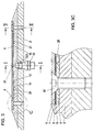
- 1 is a grooved rail.
- this Grooved rail is a device for distributing lubricants, for example attached by means of screws 32, 33, the screws 32, 33 in the bottom 11 of the Groove 10 are screwed.
- the distribution device has one in the groove 10 of the Rail 1 can be arranged, elongated plate 6, which is at least along one, such as the However, drawing shows, preferably along both longitudinal edges 24, 25 with the Recesses 22, 23 which cut along the longitudinal edge and are thus open to the edge.
- the Lubricant is supplied to these cutouts 22, 23, as shown in FIG. 5 can be seen.
- the open edges 22, 23 of the plate 6 are from one Cover plate 7 covered, which is preferably elastic at least in the coverage area is trained.
- the plate 7 or its longitudinal edge area then steers in the area of the open-edge recesses 22, 23 the lubricant against the wall of the groove.
- the cover plate 7 is in turn from one essentially covered I-shaped plate 8.
- This plate has a web 8a, whose width s is the minimum distance a between the opposing ones edge-open recesses 22, 23 of the plate 6 corresponds.
- the cover plate 7 at least in that area in which this plate 7 edge-open recesses 22, 23 covered, elastic, so it looks like a valve plate, which more or less depending on the pressure conditions edge-open recesses 22, 23 and thus the lubricant flow in different heights on the groove wall of the rail.
- the plate 7 also provides protection against intrusion Foreign bodies in the edge-open recesses 22 and 23, as they go up covers.
- the plates 6 and 7 can be designed as lamellae.
- the feed device formed in the embodiment of plates 2, 4 and 5 for the lubricant has 2 in the bottom plate (base plate) superimposed plates 2, 4 and 5 a recess 13 which extends in the longitudinal direction the plate 2 extends.
- a recess 13 which extends in the longitudinal direction the plate 2 extends.
- Feed opening 12 for the lubricant, which to the bottom plate 2 in the out the stack 9 formed on the stacked plates 2, 4, 5 has at least two through openings 14, 15, which in the stack 9 above the Recess 13 of the bottom plate 2 are arranged and thus with the recess 13 the bottom plate 2 communicate.
- the recess 13 causes a division of the lubricant flow in the longitudinal direction of the lowermost plate 2 each from the center the recess 13 towards the ends of the recess 13.
- the plate 4 can by means of countersunk screws 36, which holes 40 in the Push plate 4 through and screw it into threaded holes 48 in the bottom plate 2 are screwed to the bottom plate 2.
- the plates 2, 4 and 5 form a stack in the example shown 9 (an assembly) over which the outgoing from the edges 24, 25 Recesses 22, 23 in the plate 6 with lubricant, in the form of the number of Recesses 22, 23 corresponding partial flows are supplied.
- the Lubricant is supplied via a separate (hose) line connectable nipple 52, which is screwed into the rail 1 from below and over has an inner cone (Fig. 1, 1A).
- a cone nipple 52A which has an outer cone, suitable for the inner cone of the nipple 52 screwed into the rail 1, is in the feed opening 12 of the lowermost plate 2 is screwed in (FIGS. 1, 1A). If that entire package (2, 4, 5, 6, 7, 8) with the fastening screws 32 and 33 in the Screwed rail, the inner cone of the nipple 52 join with the The outer cone of the nipple 52A is a tight connection.
- the distribution device for the lubricant which is formed by the plates 6, 7 and 8 in the illustrated embodiment and the Feeding device for the lubricant to the lubricant discharge openings (Open-edge recesses 22, 23), which in the embodiment of the superposed plates 2, 4 and 5 is formed in the groove 10 of the rail 1st be attached.
- the feed device (plates 2, 4 and 5) could also as a unit in the groove 10 of the rail 1 are attached and on this unit the distribution device for Lubricant (plates 6, 7, 8) are placed, the attachment on the Feeder could be done for example by screws.
- the plate 4 arranged flow dividers 16, 17 are in the illustrated embodiment as I-shaped recess formed. In the bottom of the web the I-shaped There is an opening 14 or recesses in each flow divider 16, 17. 15, via which the lubricant is supplied to the flow dividers 16 and 17, respectively.
- the lubricant flows against the web 26, 27 of the I-shaped recess two flanges 28, 29 and 30, 31 of the I-shaped recesses and also fills the Flanges 28, 29 and 30, 31, from where it through through openings 18, 19, 20, 21 in a plate 5 covering the plate 4 to the lubricant discharge openings 22, 23 arrives.
- the through openings 18, 19, 20, 21 in the plate 5 come above the Flanges 28, 29 and 30, 31 of the flow dividers 16, 17 to lie.
- I-shaped die cuts are provided in the plate 4, then on one side be covered by a separate bottom, which can be detached with the plate 4 or is also permanently connected.
- the bottom is in this case with those openings 14, 15 provided which open into the I-shaped cutouts, from where the Lubricant then through the through openings 18, 19, 20 and 21 of the plate 5 to the Lubricant discharge openings reached.
Landscapes
- Engineering & Computer Science (AREA)
- Mechanical Engineering (AREA)
- Bearings For Parts Moving Linearly (AREA)
Abstract
Description
Claims (7)
- Einrichtung zum Verteilen von Schmierstoffen in Rillenschienen, insbesondere solchen für den schienengebundenen Stadtverkehr, dadurch gekennzeichnet, daß eine in der Rille (10) der Schiene (1) anordenbare, langgestreckte Platte (6) vorgesehen ist, die zumindest entlang eines, bevorzugt jedoch beider Längsränder (24, 25) mit den Längsrand anschneidenden, somit randoffenen Aussparungen (22, 23) versehen ist, welchen der Schmierstoff zuführbar ist, und daß die randoffenen Aussparungen (22, 23) der Platte (6) von einer Deckplatte (7) abgedeckt sind, welche bevorzugt mindest im Überdeckungsbereich elastisch ausgebildet ist.
- Einrichtung nach Anspruch 1, dadurch gekennzeichnet, daß die in jenem Bereich, in dem sie die randoffenen Aussparungen (22, 23) überdeckt, elastisch ausgebildete Deckplatte (7) von einer im wesentlichen I-förmigen Platte (8) abgedeckt ist, wobei die Breite (s) des Steges (8a) dieser I-förmigen Platte (8) dem Mindestabstand (a) zwischen den einander gegenüberliegenden randoffenen Aussparungen (22, 23) der die randoffenen Aussparungen (22, 23) besitzenden Platte (6) entspricht.
- Vorrichtung zur Zufuhr von Schmierstoffen zu Schmierstoffabgabeöffnungen, insbesondere in einer Einrichtung nach Anspruch 1 oder 2, dadurch gekennzeichnet, daß die Zufuhrvorrichtung mehrere Platten (2, 4, 5) aufweist, die aufeinanderliegend, als Stapel (9) in der Rille (10) der Schiene (1), insbesondere am Rillenboden (11) fixierbar sind, wobei die unterste Platte (2) der aufeinanderliegenden Platten (2, 4, 5) mit einem Strömungsteiler (13) versehen ist, der bevorzugt als langgestreckte Aussparung in der Platte (2) ausgebildet ist, wobei in den Strömungsteiler (13), bevorzugt mittig, eine Zufuhröffnung (12) für den Schmierstoff mündet und der Strömungsteiler (13) über mindestens zwei voneinander beabstandete Öff- nungen (14, 15) mit in einer weiteren Platte (4) des Stapels (9) aus aufeinanderliegenden Platten (2, 4, 5) angeordneten Strömungsteilern (16, 17) in Verbindung steht und daß im Stapel (9) auf die, die weiteren Strömungsteiler (16, 17) aufweisende Platte (4) eine über Durch- gangsöffnungen (18 - 21) mit dem bzw. den Strömungsteilern (16, 17) in Verbindung stehende und auch mit den Schmierstoffabgabeöffnungen (22, 23) in Verbindung bringbare Platte (5) folgt, welche den oder die Strömungsteiler (16, 17) der Platte (4) abdeckt.
- Einrichtung nach Anspruch 3, dadurch gekennzeichnet, daß der bzw. die in der weiteren Platte (4) angeordneten Strömungsteiler (16, 17) als Vertiefung, insbesondere von I-Form, in der Platte (4) ausgebildet sind, wobei die Öffnungen (14, 15) für die Zufuhr des Schmierstoffes zu den Strömungsteilern (16, 17) als Durchbrechungen im Boden der Vertiefung ausgebildet sind.
- Einrichtung nach Anspruch 3, dadurch gekennzeichnet, daß der bzw. die in der weiteren Platte (4) angeordneten Strömungsteiler (16, 17) als Durchbrechung, insbesondere von I-Form, in der weiteren Platte (4) ausgebildet sind, wobei die Platte (4) an einer Seite durch einen mit ihr fest verbundenen Boden abgedeckt ist, der die Durchbrechungen überbrückt und mit den in die Durchbrechungen der Platte (4) mündendenden Durchgangsöffnungen für den Schmierstoff versehen ist.
- Einrichtung nach Anspruch 3 und Anspruch 4 oder 5, dadurch gekennzeichnet, daß bei Ausbildung des oder der Strömungsteiler (16, 17) in I-Form, die Durchgangsöffnungen (18 - 21), welche den Strömungsteiler (16, 17) in der weiteren Platte (4) mit den Schmierstoffabgabeöffnungen verbinden, oberhalb der Flanschen (28 - 31) der I-förmig ausgebildeten Strömungsteiler (16, 17) liegen, wobei jedem Flansch (28 - 31), bevorzugt ein Paar von Durchgangsöffnungen (18 - 21) zugeordnet ist und daß jede dieser Durchgangsöffnungen (18 - 21) in eine der die Längsränder (24, 25) der Platte (4) bevorzugt anschneidenden, die Schmierstoffabgabeöffnungen bildenden Aussparungen (22, 23) mündet.
- Einrichtung nach einem der Ansprüche 3 - 6, dadurch gekennzeichnet, daß in die Zufuhröffnung (12) der untersten Platte (2) ein mit einem Außenkonus (52A) versehener Nippel eingesetzt, bevorzugt eingeschraubt ist, und daß der Außenkonus (52A) in eine in die Rille (10) der Schiene (1) mündende Durchgangsöffnung ragt, in welche ein mit zum Außenkonus (52A) korrespondierend ausgebildetem Innenkonus (52B) versehener weiterer Nippel (52) eingesetzt, bevorzugt eingeschraubt ist und daß der Innenkonus (52B) dichtend am Außenkonus (52A) anliegt.
Applications Claiming Priority (2)
| Application Number | Priority Date | Filing Date | Title |
|---|---|---|---|
| AT0042301A AT413371B (de) | 2001-03-16 | 2001-03-16 | Einrichtung zum verteilen von schmierstoffen in rillenschienen |
| AT4232001 | 2001-03-16 |
Publications (3)
| Publication Number | Publication Date |
|---|---|
| EP1241070A2 true EP1241070A2 (de) | 2002-09-18 |
| EP1241070A3 EP1241070A3 (de) | 2003-04-09 |
| EP1241070B1 EP1241070B1 (de) | 2012-08-29 |
Family
ID=3673977
Family Applications (1)
| Application Number | Title | Priority Date | Filing Date |
|---|---|---|---|
| EP02450061A Expired - Lifetime EP1241070B1 (de) | 2001-03-16 | 2002-03-14 | Einrichtung zum Verteilen von Schmierstoffen in Rillenschienen |
Country Status (3)
| Country | Link |
|---|---|
| US (1) | US7040452B2 (de) |
| EP (1) | EP1241070B1 (de) |
| AT (1) | AT413371B (de) |
Families Citing this family (1)
| Publication number | Priority date | Publication date | Assignee | Title |
|---|---|---|---|---|
| CN109987115A (zh) * | 2018-12-29 | 2019-07-09 | 宁波宝鑫铁路信号设备制造有限公司 | 一种槽型轨导油板、涂油器 |
Citations (1)
| Publication number | Priority date | Publication date | Assignee | Title |
|---|---|---|---|---|
| GB9411407D0 (en) | 1994-06-07 | 1994-07-27 | Harrison Richard W | Sun shade |
Family Cites Families (20)
| Publication number | Priority date | Publication date | Assignee | Title |
|---|---|---|---|---|
| DE508103C (de) * | 1930-09-24 | Arno Schwabach | Durch den Spurkranz des Rades in Wirkung tretende Vorrichtung zum Schmieren der Seitenflaechen der Rille von Rillenschienen | |
| US764108A (en) * | 1904-01-27 | 1904-07-05 | Jesse I Brewer | Switch-point protector. |
| US849966A (en) * | 1907-01-15 | 1907-04-09 | George W Blank | Lubricator. |
| US1205711A (en) * | 1915-11-01 | 1916-11-21 | Charles H Clark | Rail-lubricating device. |
| US1728412A (en) * | 1927-07-16 | 1929-09-17 | Albert G Humphries | Track lubricator |
| US1831313A (en) * | 1928-04-10 | 1931-11-10 | American Valve And Meter Compa | Track lubricating apparatus |
| DE508130C (de) | 1928-07-01 | 1930-09-27 | Union Special Maschinenfab | Saeumer, insbesondere zum Herstellen endloser Saeume |
| US1810764A (en) * | 1928-10-22 | 1931-06-16 | Maintenance Equipment Company | Wheel flange oiler |
| US1880672A (en) * | 1930-06-14 | 1932-10-04 | Maintenance Equipment Company | Wheel flange oiler |
| US1954990A (en) * | 1930-11-25 | 1934-04-17 | Lewis S Elmer | Rail lubricator |
| US1979447A (en) * | 1932-07-11 | 1934-11-06 | Butcher Edwin George | Railway and tramway rail and wheel flange lubrication |
| US1918146A (en) * | 1932-11-02 | 1933-07-11 | Ardco Mfg Company | Rail and wheel flange lubricator |
| US2016975A (en) * | 1933-09-29 | 1935-10-08 | Ardco Mfg Company | Rail flange lubricator |
| US2173654A (en) * | 1936-01-11 | 1939-09-19 | Chester F Gailor | Track lubricating apparatus |
| US2907410A (en) * | 1956-09-05 | 1959-10-06 | Ferdinand Gregorie Jr | Train rail lubricating device |
| BE622685A (de) * | 1961-09-20 | |||
| US4214647A (en) * | 1978-02-24 | 1980-07-29 | Lutts William M | Automatic rail greasing apparatus |
| US5394958A (en) * | 1992-12-22 | 1995-03-07 | Portec Inc. | Rail lubrication apparatus |
| US5641037A (en) * | 1995-06-06 | 1997-06-24 | Portec, Inc., R M P Division | Rail lubrication apparatus |
| US5609294A (en) * | 1995-07-21 | 1997-03-11 | Lucas, Jr.; Joseph | Railroad track assembly and method |
-
2001
- 2001-03-16 AT AT0042301A patent/AT413371B/de not_active IP Right Cessation
-
2002
- 2002-03-07 US US10/090,868 patent/US7040452B2/en not_active Expired - Fee Related
- 2002-03-14 EP EP02450061A patent/EP1241070B1/de not_active Expired - Lifetime
Patent Citations (1)
| Publication number | Priority date | Publication date | Assignee | Title |
|---|---|---|---|---|
| GB9411407D0 (en) | 1994-06-07 | 1994-07-27 | Harrison Richard W | Sun shade |
Also Published As
| Publication number | Publication date |
|---|---|
| US7040452B2 (en) | 2006-05-09 |
| US20020166728A1 (en) | 2002-11-14 |
| ATA4232001A (de) | 2005-07-15 |
| EP1241070B1 (de) | 2012-08-29 |
| EP1241070A3 (de) | 2003-04-09 |
| AT413371B (de) | 2006-02-15 |
Similar Documents
| Publication | Publication Date | Title |
|---|---|---|
| DE60110685T2 (de) | Montageanordnung für Ventile | |
| DE2515022B2 (de) | Leicht montierbares bzw. demontierbares Traggerüst | |
| DE2855164C2 (de) | Abdeckleistenanordnung für Bandförderer | |
| DE68905200T2 (de) | Plattenlocher. | |
| EP0643233B1 (de) | Linearführungseinrichtung | |
| DE2342248C3 (de) | Abdeckung für eine Saugvorrichtung in der Preßfilzherstellung | |
| DE3644743A1 (de) | Waelzlager-geradefuehrung | |
| DE10049348A1 (de) | Linearführungsanordnung | |
| EP0409961B1 (de) | Gleiteinlage für zungenvorrichtungen wie auch für gleitflächen für bewegliche herzstückspitzen, sowie verfahren zum befestigen einer derartigen gleiteinlage an dem gleitbett von zungenvorrichtungen | |
| EP0802102A1 (de) | Weichenendverschluss | |
| DE3500258C2 (de) | ||
| EP1558507A1 (de) | Mitnehmer für kettenkratzförderer, insbesondere des untertagebetriebes | |
| AT413371B (de) | Einrichtung zum verteilen von schmierstoffen in rillenschienen | |
| DE102010022624B4 (de) | Ventilanordnung | |
| DE102013215385A1 (de) | Spannpratze für eine Spannvorrichtung | |
| DE10157676A1 (de) | Einrichtung zum seitlichen Abstützen einer Schiene | |
| DE3741074C2 (de) | Auftragskopf zum Auftragen von Leimspuren | |
| EP0178515B1 (de) | Distanzhalter für Tropfenabscheider | |
| DE2706277B2 (de) | Siebboden | |
| EP0600435A1 (de) | Farbmesser-Lamelle und Farbmesserträger für einen Farbkasten einer Rotationsdruckmaschine | |
| EP0455973A1 (de) | Führungsleiste für Aufzugstür | |
| EP3199704B1 (de) | Segmentbogenpflaster | |
| DE19608290C1 (de) | Kettenförderer | |
| DE2353066B2 (de) | Vakuumspannvorrichtung zur Halterung von Werkstücken | |
| DE4238330C2 (de) | Schieberventil |
Legal Events
| Date | Code | Title | Description |
|---|---|---|---|
| PUAI | Public reference made under article 153(3) epc to a published international application that has entered the european phase |
Free format text: ORIGINAL CODE: 0009012 |
|
| AK | Designated contracting states |
Kind code of ref document: A2 Designated state(s): AT BE CH CY DE DK ES FI FR GB GR IE IT LI LU MC NL PT SE TR |
|
| AX | Request for extension of the european patent |
Free format text: AL;LT;LV;MK;RO;SI |
|
| PUAL | Search report despatched |
Free format text: ORIGINAL CODE: 0009013 |
|
| AK | Designated contracting states |
Designated state(s): AT BE CH CY DE DK ES FI FR GB GR IE IT LI LU MC NL PT SE TR Kind code of ref document: A3 Designated state(s): AT BE CH CY DE DK ES FI FR GB GR IE IT LI LU MC NL PT SE TR |
|
| AX | Request for extension of the european patent |
Extension state: AL LT LV MK RO SI |
|
| 17P | Request for examination filed |
Effective date: 20031009 |
|
| AKX | Designation fees paid |
Designated state(s): AT BE CH CY DE DK ES FI FR GB GR IE IT LI LU MC NL PT SE TR |
|
| 17Q | First examination report despatched |
Effective date: 20061128 |
|
| GRAP | Despatch of communication of intention to grant a patent |
Free format text: ORIGINAL CODE: EPIDOSNIGR1 |
|
| GRAS | Grant fee paid |
Free format text: ORIGINAL CODE: EPIDOSNIGR3 |
|
| GRAA | (expected) grant |
Free format text: ORIGINAL CODE: 0009210 |
|
| AK | Designated contracting states |
Kind code of ref document: B1 Designated state(s): AT BE CH CY DE DK ES FI FR GB GR IE IT LI LU MC NL PT SE TR |
|
| REG | Reference to a national code |
Ref country code: GB Ref legal event code: FG4D Free format text: NOT ENGLISH |
|
| REG | Reference to a national code |
Ref country code: CH Ref legal event code: EP |
|
| REG | Reference to a national code |
Ref country code: AT Ref legal event code: REF Ref document number: 572897 Country of ref document: AT Kind code of ref document: T Effective date: 20120915 |
|
| REG | Reference to a national code |
Ref country code: IE Ref legal event code: FG4D Free format text: LANGUAGE OF EP DOCUMENT: GERMAN |
|
| REG | Reference to a national code |
Ref country code: DE Ref legal event code: R096 Ref document number: 50215590 Country of ref document: DE Effective date: 20121025 |
|
| REG | Reference to a national code |
Ref country code: NL Ref legal event code: VDEP Effective date: 20120829 |
|
| PG25 | Lapsed in a contracting state [announced via postgrant information from national office to epo] |
Ref country code: CY Free format text: LAPSE BECAUSE OF FAILURE TO SUBMIT A TRANSLATION OF THE DESCRIPTION OR TO PAY THE FEE WITHIN THE PRESCRIBED TIME-LIMIT Effective date: 20120829 Ref country code: FI Free format text: LAPSE BECAUSE OF FAILURE TO SUBMIT A TRANSLATION OF THE DESCRIPTION OR TO PAY THE FEE WITHIN THE PRESCRIBED TIME-LIMIT Effective date: 20120829 |
|
| PG25 | Lapsed in a contracting state [announced via postgrant information from national office to epo] |
Ref country code: SE Free format text: LAPSE BECAUSE OF FAILURE TO SUBMIT A TRANSLATION OF THE DESCRIPTION OR TO PAY THE FEE WITHIN THE PRESCRIBED TIME-LIMIT Effective date: 20120829 Ref country code: GR Free format text: LAPSE BECAUSE OF FAILURE TO SUBMIT A TRANSLATION OF THE DESCRIPTION OR TO PAY THE FEE WITHIN THE PRESCRIBED TIME-LIMIT Effective date: 20121130 Ref country code: PT Free format text: LAPSE BECAUSE OF FAILURE TO SUBMIT A TRANSLATION OF THE DESCRIPTION OR TO PAY THE FEE WITHIN THE PRESCRIBED TIME-LIMIT Effective date: 20121231 |
|
| PG25 | Lapsed in a contracting state [announced via postgrant information from national office to epo] |
Ref country code: DK Free format text: LAPSE BECAUSE OF FAILURE TO SUBMIT A TRANSLATION OF THE DESCRIPTION OR TO PAY THE FEE WITHIN THE PRESCRIBED TIME-LIMIT Effective date: 20120829 Ref country code: NL Free format text: LAPSE BECAUSE OF FAILURE TO SUBMIT A TRANSLATION OF THE DESCRIPTION OR TO PAY THE FEE WITHIN THE PRESCRIBED TIME-LIMIT Effective date: 20120829 Ref country code: ES Free format text: LAPSE BECAUSE OF FAILURE TO SUBMIT A TRANSLATION OF THE DESCRIPTION OR TO PAY THE FEE WITHIN THE PRESCRIBED TIME-LIMIT Effective date: 20121210 |
|
| PG25 | Lapsed in a contracting state [announced via postgrant information from national office to epo] |
Ref country code: IT Free format text: LAPSE BECAUSE OF FAILURE TO SUBMIT A TRANSLATION OF THE DESCRIPTION OR TO PAY THE FEE WITHIN THE PRESCRIBED TIME-LIMIT Effective date: 20120829 |
|
| PLBE | No opposition filed within time limit |
Free format text: ORIGINAL CODE: 0009261 |
|
| STAA | Information on the status of an ep patent application or granted ep patent |
Free format text: STATUS: NO OPPOSITION FILED WITHIN TIME LIMIT |
|
| 26N | No opposition filed |
Effective date: 20130530 |
|
| REG | Reference to a national code |
Ref country code: DE Ref legal event code: R097 Ref document number: 50215590 Country of ref document: DE Effective date: 20130530 |
|
| BERE | Be: lapsed |
Owner name: GUNACKER, RICHARD Effective date: 20130331 |
|
| PG25 | Lapsed in a contracting state [announced via postgrant information from national office to epo] |
Ref country code: MC Free format text: LAPSE BECAUSE OF NON-PAYMENT OF DUE FEES Effective date: 20130331 |
|
| REG | Reference to a national code |
Ref country code: CH Ref legal event code: PL |
|
| GBPC | Gb: european patent ceased through non-payment of renewal fee |
Effective date: 20130314 |
|
| REG | Reference to a national code |
Ref country code: FR Ref legal event code: ST Effective date: 20131129 |
|
| REG | Reference to a national code |
Ref country code: IE Ref legal event code: MM4A |
|
| REG | Reference to a national code |
Ref country code: DE Ref legal event code: R119 Ref document number: 50215590 Country of ref document: DE Effective date: 20131001 |
|
| PG25 | Lapsed in a contracting state [announced via postgrant information from national office to epo] |
Ref country code: IE Free format text: LAPSE BECAUSE OF NON-PAYMENT OF DUE FEES Effective date: 20130314 Ref country code: GB Free format text: LAPSE BECAUSE OF NON-PAYMENT OF DUE FEES Effective date: 20130314 Ref country code: CH Free format text: LAPSE BECAUSE OF NON-PAYMENT OF DUE FEES Effective date: 20130331 Ref country code: BE Free format text: LAPSE BECAUSE OF NON-PAYMENT OF DUE FEES Effective date: 20130331 Ref country code: FR Free format text: LAPSE BECAUSE OF NON-PAYMENT OF DUE FEES Effective date: 20130402 Ref country code: LI Free format text: LAPSE BECAUSE OF NON-PAYMENT OF DUE FEES Effective date: 20130331 Ref country code: DE Free format text: LAPSE BECAUSE OF NON-PAYMENT OF DUE FEES Effective date: 20131001 |
|
| REG | Reference to a national code |
Ref country code: AT Ref legal event code: MM01 Ref document number: 572897 Country of ref document: AT Kind code of ref document: T Effective date: 20130314 |
|
| PG25 | Lapsed in a contracting state [announced via postgrant information from national office to epo] |
Ref country code: AT Free format text: LAPSE BECAUSE OF NON-PAYMENT OF DUE FEES Effective date: 20130314 |
|
| PG25 | Lapsed in a contracting state [announced via postgrant information from national office to epo] |
Ref country code: TR Free format text: LAPSE BECAUSE OF FAILURE TO SUBMIT A TRANSLATION OF THE DESCRIPTION OR TO PAY THE FEE WITHIN THE PRESCRIBED TIME-LIMIT Effective date: 20120829 |
|
| PG25 | Lapsed in a contracting state [announced via postgrant information from national office to epo] |
Ref country code: LU Free format text: LAPSE BECAUSE OF NON-PAYMENT OF DUE FEES Effective date: 20130314 |