EP1240969A2 - Verfahren zum Schweissen von ultrafeinkörnigen Eisen-Basis-Werkstoffen und so hergestellte Bauteile - Google Patents
Verfahren zum Schweissen von ultrafeinkörnigen Eisen-Basis-Werkstoffen und so hergestellte Bauteile Download PDFInfo
- Publication number
- EP1240969A2 EP1240969A2 EP02004244A EP02004244A EP1240969A2 EP 1240969 A2 EP1240969 A2 EP 1240969A2 EP 02004244 A EP02004244 A EP 02004244A EP 02004244 A EP02004244 A EP 02004244A EP 1240969 A2 EP1240969 A2 EP 1240969A2
- Authority
- EP
- European Patent Office
- Prior art keywords
- welding
- iron
- range
- average grain
- stainless steel
- Prior art date
- Legal status (The legal status is an assumption and is not a legal conclusion. Google has not performed a legal analysis and makes no representation as to the accuracy of the status listed.)
- Granted
Links
Images


Classifications
-
- B—PERFORMING OPERATIONS; TRANSPORTING
- B23—MACHINE TOOLS; METAL-WORKING NOT OTHERWISE PROVIDED FOR
- B23K—SOLDERING OR UNSOLDERING; WELDING; CLADDING OR PLATING BY SOLDERING OR WELDING; CUTTING BY APPLYING HEAT LOCALLY, e.g. FLAME CUTTING; WORKING BY LASER BEAM
- B23K20/00—Non-electric welding by applying impact or other pressure, with or without the application of heat, e.g. cladding or plating
- B23K20/12—Non-electric welding by applying impact or other pressure, with or without the application of heat, e.g. cladding or plating the heat being generated by friction; Friction welding
-
- C—CHEMISTRY; METALLURGY
- C21—METALLURGY OF IRON
- C21D—MODIFYING THE PHYSICAL STRUCTURE OF FERROUS METALS; GENERAL DEVICES FOR HEAT TREATMENT OF FERROUS OR NON-FERROUS METALS OR ALLOYS; MAKING METAL MALLEABLE, e.g. BY DECARBURISATION OR TEMPERING
- C21D9/00—Heat treatment, e.g. annealing, hardening, quenching or tempering, adapted for particular articles; Furnaces therefor
- C21D9/50—Heat treatment, e.g. annealing, hardening, quenching or tempering, adapted for particular articles; Furnaces therefor for welded joints
-
- B—PERFORMING OPERATIONS; TRANSPORTING
- B23—MACHINE TOOLS; METAL-WORKING NOT OTHERWISE PROVIDED FOR
- B23K—SOLDERING OR UNSOLDERING; WELDING; CLADDING OR PLATING BY SOLDERING OR WELDING; CUTTING BY APPLYING HEAT LOCALLY, e.g. FLAME CUTTING; WORKING BY LASER BEAM
- B23K20/00—Non-electric welding by applying impact or other pressure, with or without the application of heat, e.g. cladding or plating
- B23K20/12—Non-electric welding by applying impact or other pressure, with or without the application of heat, e.g. cladding or plating the heat being generated by friction; Friction welding
- B23K20/122—Non-electric welding by applying impact or other pressure, with or without the application of heat, e.g. cladding or plating the heat being generated by friction; Friction welding using a non-consumable tool, e.g. friction stir welding
- B23K20/1265—Non-butt welded joints, e.g. overlap-joints, T-joints or spot welds
-
- B—PERFORMING OPERATIONS; TRANSPORTING
- B23—MACHINE TOOLS; METAL-WORKING NOT OTHERWISE PROVIDED FOR
- B23K—SOLDERING OR UNSOLDERING; WELDING; CLADDING OR PLATING BY SOLDERING OR WELDING; CUTTING BY APPLYING HEAT LOCALLY, e.g. FLAME CUTTING; WORKING BY LASER BEAM
- B23K20/00—Non-electric welding by applying impact or other pressure, with or without the application of heat, e.g. cladding or plating
- B23K20/12—Non-electric welding by applying impact or other pressure, with or without the application of heat, e.g. cladding or plating the heat being generated by friction; Friction welding
- B23K20/129—Non-electric welding by applying impact or other pressure, with or without the application of heat, e.g. cladding or plating the heat being generated by friction; Friction welding specially adapted for particular articles or work
-
- B—PERFORMING OPERATIONS; TRANSPORTING
- B23—MACHINE TOOLS; METAL-WORKING NOT OTHERWISE PROVIDED FOR
- B23K—SOLDERING OR UNSOLDERING; WELDING; CLADDING OR PLATING BY SOLDERING OR WELDING; CUTTING BY APPLYING HEAT LOCALLY, e.g. FLAME CUTTING; WORKING BY LASER BEAM
- B23K20/00—Non-electric welding by applying impact or other pressure, with or without the application of heat, e.g. cladding or plating
- B23K20/22—Non-electric welding by applying impact or other pressure, with or without the application of heat, e.g. cladding or plating taking account of the properties of the materials to be welded
- B23K20/227—Non-electric welding by applying impact or other pressure, with or without the application of heat, e.g. cladding or plating taking account of the properties of the materials to be welded with ferrous layer
Definitions
- the present invention relates to a nonfusion welding process for iron-base ultra-fine grained materials and particularly to welded structural components with distinguished properties, such as strength, corrosion resistance, etc. inherited from the ultra-fine grained materials.
- the structure of the material at the fused parts is broken up by welding to form a solidification structure, and fine grains in the heat-affected zone grow to coarse grains.
- laser welding JP-A-11-170088
- electron beam welding JP-A-62-64486
- micro-arc welding JP-A-192838
- narrow gap welding JP-A-2000-246438
- JP-A-2000-015462 a welding process, which comprises placing welding pieces together, edge to edge, allowing them to rotate at high speed to effect welding by friction heating
- the temperature of the welding zone is elevated to the melting point so long as welding is carried out by melting, even if laser welding, electron beam welding, micro-arc welding or narrow gap welding is used as a means of low heat input welding, and consequently the ultra-fine structure with controlled grain sizes will be broken up at the welding zone, and thus growth of such ultra-fine crystal grains to coarse grains is inevitable in the heat-affected zone.
- An object of the present invention is to provide a nonfusion welding process for iron-base ultra-fine grained materials having the finest grain sizes among the iron-base materials widely used as structural materials, while keeping their distinguished properties of ultra-fine grained materials as inherited to a maximum, and also to provide structural components manufactured by the process.
- the present invention provides a process for welding iron-base materials, which comprises welding the same or different kinds of iron-base materials, at least one of which is an iron-base ultra-fine grained material free from any amorphous phase and having an average grain size d in a range of 10 nm ⁇ d ⁇ 5 ⁇ 10 3 nm, by friction stir welding.
- the present invention also provides a process for welding iron-base materials, where the iron-base materials are iron-base ultra-fine grained materials free from any amorphous phase, which comprises welding (a) two kinds of the ultra-fine grained materials of chemically and crystallographically same or different kinds, whose average grain sizes d are in a range of 10 nm ⁇ d ⁇ 5 ⁇ 10 3 nm or (b) one kind of the ultra-fine grained material, whose average grain sizes d are in a range of 10 nm ⁇ d ⁇ 5 ⁇ 10 3 nm with another kind or other kinds of the grained materials of chemically and crystallographically same or different kinds, whose average grain sizes d are in a range of 5 ⁇ 10 3 nm d, by friction stir welding.
- the present invention provides a process for welding iron-base materials, where the iron-base materials are austenitic stainless steel, which comprises welding (a) two kinds of the stainless steel from one another, whose average grain sizes d are in a range of 10 nm ⁇ d ⁇ 5 ⁇ 10 3 nm, or (b) one kind of the fine grained stainless steel, whose average grain sizes d are in a range of 10 nm ⁇ d ⁇ 5 ⁇ 10 3 nm, with another kind of the stainless steel, whose average grain sizes d are in a range of 5 ⁇ 10 3 nm ⁇ 3, by friction stir welding.
- the present invention provides a process for welding iron-base materials, where the iron-base materials are ferritic stainless steel with not more than 0.12 wt.% C, free from any of martensite phase and tempered martenite structure, which comprises welding (a) two kinds of the stainless steels, whose average grain sizes d are in a range of 10 nm ⁇ d ⁇ 5 ⁇ 10 3 nm, or (b) one kind of the fine grained steel, whose average grain sizes d are in a range of 10 nm ⁇ d ⁇ 5 ⁇ 10 3 nm, with another kind of the stainless steel, whose average grain sizes d are in a range of 5 ⁇ 10 3 nm ⁇ d, by friction stir welding.
- iron-base materials such as two-phase stainless steel, ultra-fine grained austenitic stainless steel, ferritic stainless steel, etc. can be likewise used for the welding, as will be mentioned later.
- iron-base materials there can be used two-phase stainless steel, fine grained materials of austenitic stainless steel, ferritic stainless steel, two-phase stainless steel, etc. as explained below.
- the present invention provides welding of iron-base fine grained materials, whose major component is iron, crystallographically free from any amorphous phase, where two fine grained materials of chemically and crystallographically same or different kinds, whose average grain sizes d are in the same range as 10 nm ⁇ d ⁇ 5 ⁇ 10 3 nm, are welded to each other by friction stir welding, i.e. a nonfusion welding process.
- friction stir welding i.e. a nonfusion welding process.
- welding of the fine grained materials is effected by friction stir welding.
- the present invention is further characterized by welding one kind of iron-base fine grained material, whose average grain sizes d are in a range of 10 nm ⁇ d ⁇ 5 ⁇ 10 3 nm, with another kind of iron-base fine grained material of chemically and crystallographically same or different kinds, whose d is in a range of 5 ⁇ 10 3 nm ⁇ d, by friction stir welding, i.e. a nonfusion welding process.
- welding of fine grained materials is effected by friction stir welding.
- the present invention concerns particularly welding of austenitic stainless steel, ferritic stainless steel with not more than 0.12 wt.% C, free from any of martensite phase tempered martensite phase, and two-phase stainless steel with both austenite phase and ferrite phase together, characterized by welding two kinds of said steels, whose average grain sizes d are in the same range of 10 nm ⁇ d ⁇ 5 ⁇ 10 3 nm, with one another by friction stir welding, i.e. a nonfusion welding process.
- welding of fine grained materials is effected by friction stir welding.
- the present invention also includes welding of stainless steel of chemically and chrystallographically different kinds in the aforementioned stainless steel.
- the present invention concerns welding of austenitic stainless steel, ferritic stainless steel free from any of martensite phase and tempered martensite phase with not more than 12 wt. % C, and two-phase stainless steel with both austenite phase and ferrite phase together, characterized by welding one kind of fine stainless steel, whose average grain sizes d are in a range of 10 nm ⁇ d ⁇ 5 ⁇ 10 3 nm, with another kind of stainless steel, whose d is in a range of 5 ⁇ 10 3 nm ⁇ d, by friction stir welding.
- welding of fine grained materials is effected by friction stir welding.
- the present invention also includes welding of stainless steel of chemically and crystallographically different kinds in the aforementioned stainless steels.
- the present invention concerns welding of ferritic steels including low-alloy steels, etc. of fine grained materials as non-stainless steels with not more than 7 wt.% Cr and with a ferrite phase base metal, and carbon steel, characterized by welding two kinds of said steel of chemically and crystallographically same or different kinds, whose average grain sizes d are in a range of 10 nm ⁇ d ⁇ 5 ⁇ 10 3 nm, with one another by friction stir welding.
- welding of fine grained materials is effected by friction stir welding.
- the present invention is characterized b welding one kind of the aforementioned steel of fine grained materials, whose average grain sizes d are in a range of 10 nm ⁇ d ⁇ 5 ⁇ 10 3 nm, with another kind of the aforementioned steel, martensitic stainless steel and mild steel of chemically and crystallographically the same or different kinds, whose average grain sizes d are in a range of 5 ⁇ 10 3 nm ⁇ d, by friction stir welding.
- welding of fine grained materials is effected by friction stir welding.
- the present invention is still furthermore characterized by welding one kind of austenitic stainless steel, ferritic stainless steel and two-phase stainless steel consisting of fine grained materials, whose average grain sizes d are in a range of 10 nm ⁇ d ⁇ 5 ⁇ 10 3 nm, with another kind of ferritic steel with not more than 7 wt.% Cr of non-stainless steel of fine grained materials, whose average grain sizes d are likewise in a range of 10 nm ⁇ d ⁇ 5 ⁇ 10 3 nm, and carbon steel by friction stir welding.
- welding of fine grained materials is effected by friction stir welding.
- the present invention is still furthermore characterized by welding one kind of austenitic stainless steel, ferritic stainless steel and two-phase stainless steel of fine grained materials, whose average grain sizes d are in a range of 10 nm ⁇ d ⁇ 5 ⁇ 10 3 nm with another kind of ferritic steel with not more than 7 wt.% Cr of non-stainless steel grained materials, whose average grain sizes d are in a range of 5 ⁇ 10 3 nm ⁇ d, and carbon steel, and furthermore martensitic stainless steel and mild steel by friction stir welding.
- welding of fine grained materials is effected by friction stir welding.
- the present invention is still furthermore characterized by welding one kind of ferritic stainless steel with not more than 7 wt.% Cr, of non-stainless steel grained materials, whose average grain sizes d are in a range of 10 nm ⁇ d ⁇ 5 ⁇ 10 3 nm, and carbon steel and another kind of austenitic stainless steel, ferritic stainless steel and two-phase stainless steel, whose average grain sizes d are in a range of 5 ⁇ 10 3 nm ⁇ d, by friction stir welding.
- welding of fine grained materials is effected by friction stir welding.
- the present invention concerns structural components made by friction stir welding of ferritic steel with not more than 7 wt.% Cr, carbon steel, where the zones including friction stir welding zone are annealed in a range of 600° to 850°C.
- friction stir welding of iron-base fine grained materials is carried out in a coolant selected from water, oil and inert gases, or while spraying the coolant in the vicinity or over the whole of the welding zone.
- the friction stir welding is a method which comprises pressing a high speed-rotating bar (tool) of a heat-resistant, hard-to-react material to parts of metallic pieces to be welded on both sides, thereby readily elevating the temperature of the parts to higher temperature of not more than the melting point due to the generated heat of friction and giving rise to plastic flow of the parts of the metallic pieces to be welded to effect stir welding of the parts on both sides.
- Friction stir welding of iron-base materials can be carried out by use of a tool with a resistance high enough to withstand elevated temperatures due to heat generation between the tool and pieces to be friction stir welded when the high speed rotating tool is pressed into the pieces and also by the resulting plastic flow and stirring and also by use of an apparatus with a rigidity high enough to withstand upward pressures developed from within the stirring zone.
- friction stir zone temperature is not more than the melting point.
- Al alloy for reference [ Masatoshi Enomoto: Light Metal Welding 36 (1998), 25 or Hisanobu Okamura, Kinya Aota and Masakuni Ekado: Light Metal 50 (2,000), 166-172], it corresponds to 2/3 of the melting point in terms of Celsius temperature grades. That is, the melting point is 1,500°C and thus the friction stir zone temperature of the neighboring iron-base materials would be about 1,000°C.
- the structure of the friction stir zone i.e. grain sizes, would grow more than the fine grains of the base metal would do, but the material structure formed after the melting in case of welding is not a solidification structure resulting in no solidification shrinkage.
- the heat-affected zone of the part in the close vicinity of the friction stir zone receives less heat hysteresis of temperature-time, so that the grains will not grow so much.
- the present invention can have such advantages as less quality change and less deformation of the materials after the welding than those in case of the conventional welding processes.
- Grain growth of ultra-fine grains is suppressed by pinning of dispersed fine particles of the compound, etc. That is, in the iron-base materials of fine grains made by forming structurally dispersed fine particles of the materials, superplasticity can be also utilized in the plastic deformation at elevated temperatures, which is so called “stirring", and the effect of grain boundary pinning of the existing ultra-fine dispersed particles is also added thereto to make higher the effect of suppression of grain growth during the welding.
- the best effect can be obtained with austenic stainless steel, ferritic stainless steel and two-phase stainless steel with an austenite phase and a ferrite phase together, all of whose average grain sizes d are 10 nm ⁇ d ⁇ 5 ⁇ 10 3 nm, or with fine grained materials such as ferritic steel with a ferrite phase base metal as non-stainless steel and carbon steel, where fine ferrite phase grains of non-stainless steel designate neither ordinary hardened structure nor tempered structure, but a sintered structure of highly processed powder or a structure of highly rolled, processed and heat-treated plate materials, though similar to each other in composition, which comprises ultra-fine grains of carbide, etc. as precipitated in the ferrite phase.
- Table 1 shows chemical composition of plate test pieces subjected to tests of the present friction stir welding, i.e. butt welding, where austenic stainless steel (Nos. 1, 2, 3 and 4), ferritic stainless steel (Nos. 5 and 6), two-phase stainless steel (No. 7), ferritic steel (No. 8) and carbon steel (No. 9) with a ferrite phase base metal as non-stainless steel, which are typical of fine grained materials, and typical materials (Nos. 10-16) having ordinary grain sizes (not less than 5 ⁇ m), which are chemically, crystallographically and structurally closest to the aforementioned materials, are given.
- Test pieces Nos. 17 and 18 are also shown in Table 1 as counterpart members to be welded to the fine grained materials.
- Table 1 also shows average grain sizes, and tensile strength and plastic elongation of the test pieces as strength data.
- Measurement of grain sizes was carried out on the TEM-observed dark-field images for materials having average grain sizes of not more than 2 ⁇ m and on SEM-observed images for those having average grain sizes of more than 2 ⁇ m.
- Test pieces Nos. 15 and 17 had a hardened and tempered structure, where old austenite grain sizes are shown as grain sizes.
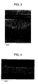
- Fig. 1 shows a picture of TEM structure of test pieces, where the average grain size was 250 nm.
- gas-atomized powder was prepared on the basis of compositions of Table 1, and processed by mechanical milling (MM) in a high energy ball mill made from stainless steel (SUS 304), using SUS 304 stainless steel balls to obtain highly processed powder.
- the processed powder weighed about 1 kg.
- MM-processed powder was subjected to vacuum canning into a mild steel can and processed by hot isostatic pressing (NIP) under isostatic pressure of 196 MPa using an inert gas as a medium.
- NIP hot isostatic pressing
- the HIP-processed materials were ultimately processed to a dimension of 3 ⁇ 50 ⁇ 200 mm 2 through a hot forging treatment. Details of processes for manufacturing fine grained materials and reference materials corresponding to the materials of Table 1 are summarized in Table 2.
- the powder is brought into a ultra-fined ferrite phase by utilizing highly processing-induced martensite transformation, and then subjected to solidification and heat processing treatment to occasion back-transformation to bring the bulk material into a fine grained austenite phase.
- the austenite phase of the two phases is made into ultra-fine grains through the same processes as above.
- Test pieces Nos. 5, 6 and 7 consisting of ferrite phase structure in part and Nos. 8 and 9 consisting of ferrite phase on the whole are adjusted by causing recrystallization in the course of solidification and heat processing step of highly processed powder, where grain growth is suppressed by precipitation of ultrafine grains of TiC or carbides of metal components in the materials, thereby producing ultra-fine grains.
- Test piece No. 8 is manufactured through the hot processing step by temperature elevation from a lower temperature, i.e. according to a process for producing ultra-fine grains without martensitic transformation, whereas the structure of test piece No. 15 of Table 1 is formed through the ordinary hardening and tempering.
- the high processing step is carried out by rolling.
- Butt welding was carried out according to welding combinations shown in Table 3, were, for example, a welding combination of No. 1 with No. 10 of Table 1 is given by "1 - 10".
- Fig. 2 is a schematic perspective view showing a method for carrying out the friction stir welding.
- Test pieces 1 and 2 in combination is placed on an iron surface plate (not shown in the drawing), abutted edge by edge, and then fixed by securing jigs 3.
- High speed-rotating tungsten bar tool 4 is inserted into a weld part and moved along weld line 5 to conduct friction stir welding.
- Weld bead 6 is formed after the welding, and a plastic flow zone, a plastic deformation zone and a heat-affected zone are formed from the center of weld cross-section 7 towards the base metal.
- Said tungsten tool 4 has a convex tip end, and on M screw is threaded at the small-diameter part (pin) at the remotest part of the tip end.
- the dimension of the small-diameter shoulder part is 5 mm in diameter and about 3 mm long. Large-diameter part is 10 mm in diameter. The small-diameter part is kept as inserted into the material until the shoulder part comes in contact with the pieces to be welded.
- Rotation speed is set to 1,300 rpm and the moving speed is set to 150 mm/min.
- the rotation speed and the moving speed are variable, but in this Example, they were set as given above.
- Welding temperature was measured at welding of test pieces Nos. 1, 5, 8 and 18 by embedding a thermocouple into the abutted pieces at the back side.
- Temperature just on the back side of welding bead was in a range of 950° to 1,150°C in all the cases, which was corresponded to about 2/3 of the melting points as in the case of the aforementioned Al alloy.
- Downward load was measured at the welding by a load cell provided at the back side of the test pieces-fixed surface plate, and it was found that the pressure on the tool at the welding was 25 to 65 MPa.
- Fig. 3 shows a picture of 1-1 joint appearance as a typical example
- Fig. 5 shows a picture of cross-section thereof at the joint. It is apparent from these pictures that welding was effected without any welding failure.
- Weld bead width was substantially identical with tool shoulder diameter, and it was found from the cross-sectional shape that the abutted edges of 1-1 joint were welded down to the back side as if the abutted edge zones were completely stirred. In all the butt welding tests as given in Table 3, similar results were obtained. Structurally, the grain sizes in the stirred zone of 1-1 joint was 440 nm and thus the grains were not so coarsened. That is, it can be concluded that the friction stir welding is a welding process capable of sufficiently maintaining a fine grained structure.
- Table 3 summaries features of evaluation results of butt welding tests according to this Example. Evaluation of grain sizes in the stirred zone was made on the basis of average grain sizes d of fine grains:
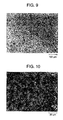
- Fig. 9 shows a structure at boundary between the joint of 8-18 and No. 18 base material. As shown in Fig. 10, a martensitic structure is formed. In such structures, the strength characteristics were found unsatisfactory, and the tensile tests revealed that the readily deformable base metal took part in deformation.
- Example 1 Weldability of fine grained materials can be basically well evaluated by the butt welding of Example 1.
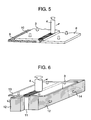
- This Example shows various welding processes to be utilized for the welded structural components, where embodiments of lap welding as shown in Fig. 5 will be described. Though the lap welding differs from butt welding, combinations of 1-1, 1-10 and -12 of Table 3 were used as typical examples.
- Overlapping width was 15 mm.
- Tungsten tool 4 12 mm in shoulder diameter, 6 mm in pin diameter, and 5 mm in pin length, was used for welding at a rotation speed of 1,500 rpm and a moving speed of 150 mm/min.
- Welding depth was 5 mm-odd, where the lower plate material 8 was stir welded down to 2 mm-odd.
- Iron support materials 12 were arranged to pinch one upright plate material 11, and another plate material 13 was placed thereon so that the center line of plate material 13 could be located on said upright plate material 11.
- the plate materials each were fixed by press jigs 3 and 14.
- Tip end dimensions of tungsten tool 4 were the same as in Example 2. Welding was carried out at a rotation speed of 1,500 rpm and a moving speed of 150 mm/min. Welding state was the same as in Example 2.
- Plate material of No. 1, 3, 5 or 7, in dimensions of 3 ⁇ 100 ⁇ 200 m 3 was deformed by bending to form cylindrical material 15, and then iron support plate 16 was abutted thereto along a line just under the butt line, i.e. weld line 5. Then, side edges of cylindrical material 15 were subjected to tack welding 17 by spot welding or friction stir welding so that the side edges may not be departed from each other.
- Tungsten tool 4 had such tip end dimensions as 8 mm in shoulder diameter, 4 mm in pin diameter and less than 2 mm in length. Welding was carried out at a rotation speed of 1,700 rpm and a moving speed of 130 mm/min.
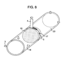
- Pipes were each 150 mm long.
- Disc-shaped support material 19 having a diameter sufficiently close to the pipe inner diameter was inserted into pipe material 18 to a depth of nearly one-half of the disc thickness, whereas other half of the disc was inserted into another pipe 20.
- Tack welding was carried out at 4 diagonally located points to prevent the abutted edges (weld line 5) from departing from each other as in Example 4.
- Both outer ends of pipes were fixed by press jigs 3, and then tool 4 was inserted into weld line 5.
- Tool 4 was rotated at a rotation speed of 1,700 rpm, but not moved, whereas the entirely of the pipes was rotated at the center of the pipes to weld both pipes at a weld moving speed of 130 mm/min.
- Friction stir welding can be fully applied to welding of structural components based on combinations with fine grained materials.
- joints between fine grained materials themselves or between fine grained materials and grained materials having grain sizes of not less than 5 ⁇ m can be obtained without impairing distinguished strength and corrosion resistance of ultra-fine grained materials, or structural components including straight or curved joints can be manufactured.
- the structural components including the aforementioned joints show distinguished characteristics, e.g. strength, corrosion resistance, etc. of ultra-fine grained materials.
Landscapes
- Engineering & Computer Science (AREA)
- Mechanical Engineering (AREA)
- Chemical & Material Sciences (AREA)
- Physics & Mathematics (AREA)
- Thermal Sciences (AREA)
- Crystallography & Structural Chemistry (AREA)
- Materials Engineering (AREA)
- Metallurgy (AREA)
- Organic Chemistry (AREA)
- Pressure Welding/Diffusion-Bonding (AREA)
Applications Claiming Priority (2)
| Application Number | Priority Date | Filing Date | Title |
|---|---|---|---|
| JP2001074463A JP2002273579A (ja) | 2001-03-15 | 2001-03-15 | 鉄基材料の接合方法およびその構造物 |
| JP2001074463 | 2001-03-15 |
Publications (3)
| Publication Number | Publication Date |
|---|---|
| EP1240969A2 true EP1240969A2 (de) | 2002-09-18 |
| EP1240969A3 EP1240969A3 (de) | 2004-05-12 |
| EP1240969B1 EP1240969B1 (de) | 2009-09-16 |
Family
ID=18931726
Family Applications (1)
| Application Number | Title | Priority Date | Filing Date |
|---|---|---|---|
| EP02004244A Expired - Lifetime EP1240969B1 (de) | 2001-03-15 | 2002-02-26 | Verfahren zum Schweissen von ultrafeinkörnigen Eisen-Basis-Werkstoffen und so hergestellte Bauteile |
Country Status (6)
| Country | Link |
|---|---|
| US (1) | US6585148B2 (de) |
| EP (1) | EP1240969B1 (de) |
| JP (1) | JP2002273579A (de) |
| KR (1) | KR20020074068A (de) |
| CN (1) | CN1179815C (de) |
| DE (1) | DE60233698D1 (de) |
Cited By (6)
| Publication number | Priority date | Publication date | Assignee | Title |
|---|---|---|---|---|
| US6585148B2 (en) * | 2001-03-15 | 2003-07-01 | Hitachi, Ltd. | Welding processes for iron-base ultra fine grained materials and structural components manufactured by the processes |
| US6780525B2 (en) * | 2001-12-26 | 2004-08-24 | The Boeing Company | High strength friction stir welding |
| WO2008139222A1 (en) * | 2007-05-11 | 2008-11-20 | Luxfer Group Limited | Method for manufacturing tanks |
| GB2439159B (en) * | 2004-04-30 | 2009-06-24 | Tokyu Car Corp | Method of connecting metal material |
| US20150007912A1 (en) * | 2012-03-14 | 2015-01-08 | Osaka University | Method for manufacturing ferrous material |
| CN115058571A (zh) * | 2022-05-27 | 2022-09-16 | 北京科技大学 | 基于搅拌摩擦加工的具有奥氏体含量梯度高强钢制备方法 |
Families Citing this family (45)
| Publication number | Priority date | Publication date | Assignee | Title |
|---|---|---|---|---|
| ES2175326T3 (es) * | 1997-12-19 | 2002-11-16 | Esab Ab | Aparato de soldadura. |
| DE10035332C1 (de) * | 2000-07-20 | 2002-02-28 | Eads Deutschland Gmbh | Verfahren und Vorrichtung zum Reibrührschweißen |
| JP3795824B2 (ja) * | 2002-04-16 | 2006-07-12 | 株式会社日立製作所 | 摩擦攪拌接合方法 |
| US6742697B2 (en) * | 2002-04-29 | 2004-06-01 | The Boeing Company | Joining of structural members by friction plug welding |
| US6908690B2 (en) * | 2002-04-29 | 2005-06-21 | The Boeing Company | Method and apparatus for friction stir welding |
| US6726085B2 (en) * | 2002-05-14 | 2004-04-27 | The Boeing Company | Method and apparatus for producing a refined grain structure |
| US20040250404A1 (en) * | 2003-01-14 | 2004-12-16 | Cripsey Timothy J. | Process for press forming metal tubes |
| WO2004091839A2 (en) * | 2003-04-11 | 2004-10-28 | Edison Welding Institute | Method and apparatus for locally clamping components that are to be joined by friction stir welding |
| US7032800B2 (en) * | 2003-05-30 | 2006-04-25 | General Electric Company | Apparatus and method for friction stir welding of high strength materials, and articles made therefrom |
| JP2005021931A (ja) * | 2003-06-30 | 2005-01-27 | Tokyu Car Corp | 板材の重ね接合方法および重ね接合構造 |
| KR100543160B1 (ko) * | 2003-10-01 | 2006-01-20 | 한국기계연구원 | 박판접합용 표면이동 마찰용접방법 |
| JP2005239029A (ja) * | 2004-02-27 | 2005-09-08 | Kawasaki Heavy Ind Ltd | 鉄道車両構体 |
| KR100571522B1 (ko) * | 2004-06-24 | 2006-04-17 | 한국기계연구원 | 표면이동마찰용접법에 의한 미세립 금속판재의 고상접합방법 |
| JP4695355B2 (ja) * | 2004-07-15 | 2011-06-08 | 新日本製鐵株式会社 | 溶接部疲労強度に優れる建設機械のブーム・アーム部材およびその製造方法 |
| JP4643319B2 (ja) * | 2005-03-15 | 2011-03-02 | 株式会社東芝 | 複合材料、その製造方法および複合材料製造装置 |
| US8298480B2 (en) * | 2005-03-16 | 2012-10-30 | Siemens Energy, Inc. | Manufacture of specialized alloys with specific properties |
| US7240821B2 (en) * | 2005-07-21 | 2007-07-10 | The Boeing Company | Method for joining at least two adjoining work-pieces by friction stir and/or friction stir spot welding |
| JP4744987B2 (ja) * | 2005-09-01 | 2011-08-10 | 国立大学法人大阪大学 | 摩擦攪拌接合方法 |
| US8141768B2 (en) * | 2006-01-27 | 2012-03-27 | Exxonmobil Research And Engineering Company | Application of high integrity welding and repair of metal components in oil and gas exploration, production and refining |
| US20070175967A1 (en) * | 2006-01-27 | 2007-08-02 | Narasimha-Rao Venkata Bangaru | High integrity welding and repair of metal components |
| JP5187712B2 (ja) * | 2006-03-09 | 2013-04-24 | 大陽日酸株式会社 | 接合方法 |
| US20100178526A1 (en) * | 2006-08-21 | 2010-07-15 | Osaka University | Process for working metal members and structures |
| EP2067564B1 (de) | 2006-08-25 | 2013-02-27 | Osaka University | Verfahren zum rührreibschweissen von metallmaterial |
| JP2010501360A (ja) * | 2006-08-30 | 2010-01-21 | フルオー・テクノロジーズ・コーポレイシヨン | 異種材料溶接のための構成および方法 |
| JP4770661B2 (ja) * | 2006-09-19 | 2011-09-14 | マツダ株式会社 | 摩擦点接合方法 |
| JP4867538B2 (ja) * | 2006-09-19 | 2012-02-01 | マツダ株式会社 | 摩擦接合方法 |
| US7617750B2 (en) * | 2006-12-06 | 2009-11-17 | Purdue Research Foundation | Process of producing nanocrystalline bodies |
| US20080311420A1 (en) * | 2007-06-15 | 2008-12-18 | Pratt & Whitney Rocketdyne, Inc. | Friction stir welding of oxide dispersion strengthened alloys |
| US10843291B2 (en) * | 2008-11-15 | 2020-11-24 | The Boeing Company | Welding in preparation for superplastic forming |
| US20100136369A1 (en) * | 2008-11-18 | 2010-06-03 | Raghavan Ayer | High strength and toughness steel structures by friction stir welding |
| JP5501647B2 (ja) * | 2009-03-26 | 2014-05-28 | 国立大学法人大阪大学 | 鋳鉄材・鋼材の表面硬化処理方法 |
| US8220693B2 (en) * | 2009-11-09 | 2012-07-17 | GM Global Technology Operations LLC | Modified surfaces using friction stir processing |
| WO2013027532A1 (ja) * | 2011-08-19 | 2013-02-28 | 日本軽金属株式会社 | 摩擦攪拌接合方法 |
| KR101166886B1 (ko) * | 2012-04-23 | 2012-07-18 | (주)금강 | 환형으로 권취가 용이한 금속 수지 복합관 및, 그 제조방법 |
| JP5803992B2 (ja) * | 2012-07-03 | 2015-11-04 | 日本軽金属株式会社 | 伝熱板の製造方法 |
| US20140255620A1 (en) * | 2013-03-06 | 2014-09-11 | Rolls-Royce Corporation | Sonic grain refinement of laser deposits |
| JP6082866B2 (ja) | 2013-09-27 | 2017-02-22 | 国立研究開発法人産業技術総合研究所 | ステンレス鋼部材の接合方法およびステンレス鋼 |
| CN103600167B (zh) * | 2013-11-15 | 2015-11-18 | 太原科技大学 | 一种碳素钢与不锈钢复合板的焊接方法 |
| MX2016006485A (es) | 2013-11-25 | 2016-08-05 | Magna Int Inc | Componente estructural que incluye zona de transicion templada. |
| JP2018051563A (ja) * | 2016-09-26 | 2018-04-05 | 日本軽金属株式会社 | 接合方法 |
| GB2553531B (en) * | 2016-09-07 | 2019-02-06 | Rolls Royce Plc | A method of attaching a projection to a thin walled component |
| JP6743643B2 (ja) * | 2016-10-18 | 2020-08-19 | 日本軽金属株式会社 | 中空容器の製造方法 |
| CN113661027A (zh) * | 2019-03-27 | 2021-11-16 | 国立大学法人大阪大学 | 钢铁材料的表面改性方法和钢铁结构物 |
| KR102084949B1 (ko) * | 2019-04-30 | 2020-03-05 | 에이에프더블류 주식회사 | 부스바 제조방법 |
| WO2022010718A1 (en) * | 2020-07-09 | 2022-01-13 | Lam Research Corporation | Friction stir processing for corrosion resistance |
Family Cites Families (10)
| Publication number | Priority date | Publication date | Assignee | Title |
|---|---|---|---|---|
| US3273233A (en) * | 1964-10-27 | 1966-09-20 | Caterpillar Tractor Co | Method of bonding metal workpieces |
| NO942790D0 (no) | 1994-03-28 | 1994-07-27 | Norsk Hydro As | Fremgangsmåte ved friksjonssveising og anordning for samme |
| JPH09192838A (ja) | 1996-01-19 | 1997-07-29 | Kobe Steel Ltd | アルミニウム薄板t型継手のすみ肉ミグアーク溶接方法 |
| JP3070735B2 (ja) * | 1997-07-23 | 2000-07-31 | 株式会社日立製作所 | 摩擦攪拌接合方法 |
| JP3735195B2 (ja) | 1997-12-04 | 2006-01-18 | 新日本製鐵株式会社 | 鋼材の熱間レーザー溶接用メタルコアード型フィラワイヤ |
| DE69816585T2 (de) * | 1998-01-16 | 2004-05-13 | Daido Tokushuko K.K., Nagoya | Methode zu Untersuchung von Metall-Verbunden mittels Ultraschall |
| JP2000015462A (ja) | 1998-07-03 | 2000-01-18 | Hitachi Metals Ltd | 摩擦圧接部材およびその製造方法 |
| JP2000246438A (ja) | 1999-02-26 | 2000-09-12 | Hitachi Ltd | 構造物とその溶接方法 |
| US6398883B1 (en) * | 2000-06-07 | 2002-06-04 | The Boeing Company | Friction stir grain refinement of structural members |
| JP2002273579A (ja) * | 2001-03-15 | 2002-09-25 | Hitachi Ltd | 鉄基材料の接合方法およびその構造物 |
-
2001
- 2001-03-15 JP JP2001074463A patent/JP2002273579A/ja active Pending
-
2002
- 2002-02-25 US US10/081,181 patent/US6585148B2/en not_active Expired - Fee Related
- 2002-02-26 DE DE60233698T patent/DE60233698D1/de not_active Expired - Lifetime
- 2002-02-26 KR KR1020020010225A patent/KR20020074068A/ko not_active Withdrawn
- 2002-02-26 EP EP02004244A patent/EP1240969B1/de not_active Expired - Lifetime
- 2002-02-28 CN CNB021066345A patent/CN1179815C/zh not_active Expired - Fee Related
Cited By (8)
| Publication number | Priority date | Publication date | Assignee | Title |
|---|---|---|---|---|
| US6585148B2 (en) * | 2001-03-15 | 2003-07-01 | Hitachi, Ltd. | Welding processes for iron-base ultra fine grained materials and structural components manufactured by the processes |
| US6780525B2 (en) * | 2001-12-26 | 2004-08-24 | The Boeing Company | High strength friction stir welding |
| GB2439159B (en) * | 2004-04-30 | 2009-06-24 | Tokyu Car Corp | Method of connecting metal material |
| WO2008139222A1 (en) * | 2007-05-11 | 2008-11-20 | Luxfer Group Limited | Method for manufacturing tanks |
| US20150007912A1 (en) * | 2012-03-14 | 2015-01-08 | Osaka University | Method for manufacturing ferrous material |
| US9617613B2 (en) * | 2012-03-14 | 2017-04-11 | Osaka University | Method for manufacturing ferrous material |
| CN115058571A (zh) * | 2022-05-27 | 2022-09-16 | 北京科技大学 | 基于搅拌摩擦加工的具有奥氏体含量梯度高强钢制备方法 |
| CN115058571B (zh) * | 2022-05-27 | 2024-04-16 | 北京科技大学 | 基于搅拌摩擦加工的具有奥氏体含量梯度高强钢制备方法 |
Also Published As
| Publication number | Publication date |
|---|---|
| KR20020074068A (ko) | 2002-09-28 |
| EP1240969A3 (de) | 2004-05-12 |
| DE60233698D1 (de) | 2009-10-29 |
| US6585148B2 (en) | 2003-07-01 |
| CN1179815C (zh) | 2004-12-15 |
| EP1240969B1 (de) | 2009-09-16 |
| US20030047587A1 (en) | 2003-03-13 |
| CN1375376A (zh) | 2002-10-23 |
| JP2002273579A (ja) | 2002-09-25 |
Similar Documents
| Publication | Publication Date | Title |
|---|---|---|
| EP1240969A2 (de) | Verfahren zum Schweissen von ultrafeinkörnigen Eisen-Basis-Werkstoffen und so hergestellte Bauteile | |
| Sathiya et al. | Mechanical and metallurgical properties of friction welded AISI 304 austenitic stainless steel | |
| Kumar et al. | Microstructure and mechanical properties of friction stir welded AISI 316L austenitic stainless steel joints | |
| Binesh | Diffusion brazing of IN718/AISI 316L dissimilar joint: Microstructure evolution and mechanical properties | |
| Tang et al. | Microstructure and properties of CLAM/316L steel friction stir welded joints | |
| JPWO2017022184A1 (ja) | 摩擦接合方法 | |
| Théodore et al. | Relationship between microstructure, and residual strain and stress in stainless steels in-situ alloyed by double-wire arc additive manufacturing (D-WAAM) process | |
| JPWO2018168687A1 (ja) | 摩擦圧接方法 | |
| Huysmans et al. | Weldability study of additive manufactured 316L austenitic stainless steel components—Welding of AM with conventional 316L components | |
| Kellai et al. | Effect of post weld heat treatment on the microstructure and mechanical properties of a gas-tungsten-arc-welded 304 stainless steel | |
| Vicharapu et al. | Degradation of nickel-bonded tungsten carbide tools in friction stir welding of high carbon steel | |
| Chaudhari et al. | Experimental investigation of dissimilar metal weld of SA335 P11 and SA312 TP304 formed by gas tungsten arc welding (GTAW) | |
| Dinaharan et al. | An assessment of microstructure and tensile behavior of magnetically impelled arc butt welded AISI 409 ferritic stainless steel tubes | |
| Roussos et al. | Microstructural and mechanical properties of laser cladding-deposited AISI 1060 steel with a mixture of 410L alloy and 4140 alloy powders | |
| Shunmugasamy et al. | Friction stir welding of low-carbon AISI 1006 steel: room and high-temperature mechanical properties | |
| Kim et al. | Experimental investigation on the laser welding characteristics of 6061-T6 aluminum alloy sheets | |
| Sivakumar et al. | Influence of tool rotational speed on the mechanical and microstructural properties of AISI 316 Austenitic stainless steel friction stir welded joints | |
| Moradi et al. | Studying the impact of multi-pass friction stir processing on microstructure and mechanical properties of low-carbon steel. | |
| Abdullahi | Effect of tempering treatment on the post-weld properties and chemical compositions of arc-welded alloy steels | |
| Hormozi et al. | Investigating the Effect of Friction Stir Welding on the Mechanical and Metallurgical Properties of Joining CK45 Steel to AISI 304L Stainless Steel | |
| Ghosh et al. | High-Joint Efficiency of Vacuum Diffusion-Welded Dissimilar Rods of Ti-6Al-4V and 304L Stainless Steel Without Interlayer | |
| Korra et al. | Effect of welding processes on the microstructure and mechanical properties of duplex stainless steel weld joints | |
| Dahmen et al. | Laser beam welding of ultra-high strength chromium steel with martensitic microstructure | |
| Zhang et al. | Effect of Annealing Temperature on Microstructure Evolution, Tensile Property and Deformation Behavior of Electron Beam Welded S32101 Joints | |
| JP7817738B2 (ja) | 固相接合用鋼、固相接合用鋼材、固相接合継手及び固相接合構造物 |
Legal Events
| Date | Code | Title | Description |
|---|---|---|---|
| PUAI | Public reference made under article 153(3) epc to a published international application that has entered the european phase |
Free format text: ORIGINAL CODE: 0009012 |
|
| AK | Designated contracting states |
Kind code of ref document: A2 Designated state(s): AT BE CH CY DE DK ES FI FR GB GR IE IT LI LU MC NL PT SE TR |
|
| AX | Request for extension of the european patent |
Free format text: AL;LT;LV;MK;RO;SI |
|
| PUAL | Search report despatched |
Free format text: ORIGINAL CODE: 0009013 |
|
| AK | Designated contracting states |
Kind code of ref document: A3 Designated state(s): AT BE CH CY DE DK ES FI FR GB GR IE IT LI LU MC NL PT SE TR |
|
| AX | Request for extension of the european patent |
Extension state: AL LT LV MK RO SI |
|
| 17P | Request for examination filed |
Effective date: 20040903 |
|
| AKX | Designation fees paid |
Designated state(s): DE GB |
|
| GRAP | Despatch of communication of intention to grant a patent |
Free format text: ORIGINAL CODE: EPIDOSNIGR1 |
|
| GRAS | Grant fee paid |
Free format text: ORIGINAL CODE: EPIDOSNIGR3 |
|
| RIN1 | Information on inventor provided before grant (corrected) |
Inventor name: OKAMOTO, KAZUTAKA,H Inventor name: DOI, MASAYUKI,H Inventor name: ISHIBASHI, RYO,H Inventor name: AONO, YASUHISA,H Inventor name: OKAMURA, HISANORI,H |
|
| GRAA | (expected) grant |
Free format text: ORIGINAL CODE: 0009210 |
|
| RAP1 | Party data changed (applicant data changed or rights of an application transferred) |
Owner name: HITACHI, LTD. |
|
| AK | Designated contracting states |
Kind code of ref document: B1 Designated state(s): DE GB |
|
| REG | Reference to a national code |
Ref country code: GB Ref legal event code: FG4D |
|
| REF | Corresponds to: |
Ref document number: 60233698 Country of ref document: DE Date of ref document: 20091029 Kind code of ref document: P |
|
| PLBE | No opposition filed within time limit |
Free format text: ORIGINAL CODE: 0009261 |
|
| STAA | Information on the status of an ep patent application or granted ep patent |
Free format text: STATUS: NO OPPOSITION FILED WITHIN TIME LIMIT |
|
| 26N | No opposition filed |
Effective date: 20100617 |
|
| PGFP | Annual fee paid to national office [announced via postgrant information from national office to epo] |
Ref country code: GB Payment date: 20140226 Year of fee payment: 13 |
|
| PGFP | Annual fee paid to national office [announced via postgrant information from national office to epo] |
Ref country code: DE Payment date: 20140417 Year of fee payment: 13 |
|
| REG | Reference to a national code |
Ref country code: DE Ref legal event code: R119 Ref document number: 60233698 Country of ref document: DE |
|
| GBPC | Gb: european patent ceased through non-payment of renewal fee |
Effective date: 20150226 |
|
| PG25 | Lapsed in a contracting state [announced via postgrant information from national office to epo] |
Ref country code: GB Free format text: LAPSE BECAUSE OF NON-PAYMENT OF DUE FEES Effective date: 20150226 Ref country code: DE Free format text: LAPSE BECAUSE OF NON-PAYMENT OF DUE FEES Effective date: 20150901 |