EP1240937B1 - Verfahren und Vorrichtung zur Beseitigung von Perfluorverbindungen - Google Patents
Verfahren und Vorrichtung zur Beseitigung von Perfluorverbindungen Download PDFInfo
- Publication number
- EP1240937B1 EP1240937B1 EP01119737A EP01119737A EP1240937B1 EP 1240937 B1 EP1240937 B1 EP 1240937B1 EP 01119737 A EP01119737 A EP 01119737A EP 01119737 A EP01119737 A EP 01119737A EP 1240937 B1 EP1240937 B1 EP 1240937B1
- Authority
- EP
- European Patent Office
- Prior art keywords
- gas
- discharged
- piping
- ejector
- perfluorocompounds
- Prior art date
- Legal status (The legal status is an assumption and is not a legal conclusion. Google has not performed a legal analysis and makes no representation as to the accuracy of the status listed.)
- Expired - Lifetime
Links
- 238000000034 method Methods 0.000 title claims description 10
- 239000007789 gas Substances 0.000 claims description 285
- XLYOFNOQVPJJNP-UHFFFAOYSA-N water Substances O XLYOFNOQVPJJNP-UHFFFAOYSA-N 0.000 claims description 113
- 239000003054 catalyst Substances 0.000 claims description 46
- 238000005406 washing Methods 0.000 claims description 39
- 239000002253 acid Substances 0.000 claims description 38
- 239000007921 spray Substances 0.000 claims description 31
- 238000000354 decomposition reaction Methods 0.000 claims description 29
- 239000004065 semiconductor Substances 0.000 claims description 26
- 239000003595 mist Substances 0.000 claims description 18
- 239000012670 alkaline solution Substances 0.000 claims description 11
- 229910052751 metal Inorganic materials 0.000 claims description 4
- 239000002184 metal Substances 0.000 claims description 4
- 238000003421 catalytic decomposition reaction Methods 0.000 claims description 3
- 229910052742 iron Inorganic materials 0.000 claims description 3
- 229910052759 nickel Inorganic materials 0.000 claims description 3
- 229910052697 platinum Inorganic materials 0.000 claims description 3
- 229910052718 tin Inorganic materials 0.000 claims description 3
- 229910052719 titanium Inorganic materials 0.000 claims description 3
- 229910052725 zinc Inorganic materials 0.000 claims description 3
- 229910052726 zirconium Inorganic materials 0.000 claims description 3
- 238000000926 separation method Methods 0.000 claims 2
- 230000002378 acidificating effect Effects 0.000 claims 1
- 238000007599 discharging Methods 0.000 claims 1
- 229920006926 PFC Polymers 0.000 description 84
- 238000005530 etching Methods 0.000 description 36
- 238000006243 chemical reaction Methods 0.000 description 28
- 238000002347 injection Methods 0.000 description 22
- 239000007924 injection Substances 0.000 description 22
- VYPSYNLAJGMNEJ-UHFFFAOYSA-N Silicium dioxide Chemical compound O=[Si]=O VYPSYNLAJGMNEJ-UHFFFAOYSA-N 0.000 description 20
- 238000004519 manufacturing process Methods 0.000 description 19
- KZBUYRJDOAKODT-UHFFFAOYSA-N Chlorine Chemical compound ClCl KZBUYRJDOAKODT-UHFFFAOYSA-N 0.000 description 16
- WMIYKQLTONQJES-UHFFFAOYSA-N hexafluoroethane Chemical compound FC(F)(F)C(F)(F)F WMIYKQLTONQJES-UHFFFAOYSA-N 0.000 description 15
- 238000004088 simulation Methods 0.000 description 15
- 238000005260 corrosion Methods 0.000 description 14
- 230000007797 corrosion Effects 0.000 description 14
- 238000011282 treatment Methods 0.000 description 14
- CPELXLSAUQHCOX-UHFFFAOYSA-N Hydrogen bromide Chemical compound Br CPELXLSAUQHCOX-UHFFFAOYSA-N 0.000 description 11
- 238000001816 cooling Methods 0.000 description 11
- 238000007689 inspection Methods 0.000 description 11
- 229910052681 coesite Inorganic materials 0.000 description 10
- 229910052906 cristobalite Inorganic materials 0.000 description 10
- 239000000377 silicon dioxide Substances 0.000 description 10
- 229910052682 stishovite Inorganic materials 0.000 description 10
- 229910052905 tridymite Inorganic materials 0.000 description 10
- VEXZGXHMUGYJMC-UHFFFAOYSA-N Hydrochloric acid Chemical compound Cl VEXZGXHMUGYJMC-UHFFFAOYSA-N 0.000 description 9
- 229910000041 hydrogen chloride Inorganic materials 0.000 description 9
- IXCSERBJSXMMFS-UHFFFAOYSA-N hydrogen chloride Substances Cl.Cl IXCSERBJSXMMFS-UHFFFAOYSA-N 0.000 description 9
- 238000012423 maintenance Methods 0.000 description 9
- XUIMIQQOPSSXEZ-UHFFFAOYSA-N Silicon Chemical compound [Si] XUIMIQQOPSSXEZ-UHFFFAOYSA-N 0.000 description 8
- QAOWNCQODCNURD-UHFFFAOYSA-N Sulfuric acid Chemical compound OS(O)(=O)=O QAOWNCQODCNURD-UHFFFAOYSA-N 0.000 description 8
- 229910052710 silicon Inorganic materials 0.000 description 8
- 239000010703 silicon Substances 0.000 description 8
- 229910004014 SiF4 Inorganic materials 0.000 description 7
- 238000010438 heat treatment Methods 0.000 description 7
- ABTOQLMXBSRXSM-UHFFFAOYSA-N silicon tetrafluoride Chemical compound F[Si](F)(F)F ABTOQLMXBSRXSM-UHFFFAOYSA-N 0.000 description 7
- PNEYBMLMFCGWSK-UHFFFAOYSA-N aluminium oxide Inorganic materials [O-2].[O-2].[O-2].[Al+3].[Al+3] PNEYBMLMFCGWSK-UHFFFAOYSA-N 0.000 description 6
- 238000010586 diagram Methods 0.000 description 5
- 229910000042 hydrogen bromide Inorganic materials 0.000 description 5
- 238000003825 pressing Methods 0.000 description 5
- 239000000243 solution Substances 0.000 description 5
- 235000012431 wafers Nutrition 0.000 description 5
- OKTJSMMVPCPJKN-UHFFFAOYSA-N Carbon Chemical compound [C] OKTJSMMVPCPJKN-UHFFFAOYSA-N 0.000 description 4
- PXGOKWXKJXAPGV-UHFFFAOYSA-N Fluorine Chemical compound FF PXGOKWXKJXAPGV-UHFFFAOYSA-N 0.000 description 4
- 239000006227 byproduct Substances 0.000 description 4
- 229910052593 corundum Inorganic materials 0.000 description 4
- 239000011737 fluorine Substances 0.000 description 4
- 229910052731 fluorine Inorganic materials 0.000 description 4
- 239000007788 liquid Substances 0.000 description 4
- 238000012856 packing Methods 0.000 description 4
- 239000002245 particle Substances 0.000 description 4
- 229920003023 plastic Polymers 0.000 description 4
- 239000004033 plastic Substances 0.000 description 4
- 239000011347 resin Substances 0.000 description 4
- 229920005989 resin Polymers 0.000 description 4
- 238000012360 testing method Methods 0.000 description 4
- 238000011144 upstream manufacturing Methods 0.000 description 4
- 229910001845 yogo sapphire Inorganic materials 0.000 description 4
- IJGRMHOSHXDMSA-UHFFFAOYSA-N Atomic nitrogen Chemical compound N#N IJGRMHOSHXDMSA-UHFFFAOYSA-N 0.000 description 3
- GRYLNZFGIOXLOG-UHFFFAOYSA-N Nitric acid Chemical compound O[N+]([O-])=O GRYLNZFGIOXLOG-UHFFFAOYSA-N 0.000 description 3
- HEMHJVSKTPXQMS-UHFFFAOYSA-M Sodium hydroxide Chemical compound [OH-].[Na+] HEMHJVSKTPXQMS-UHFFFAOYSA-M 0.000 description 3
- BZHJMEDXRYGGRV-UHFFFAOYSA-N Vinyl chloride Chemical compound ClC=C BZHJMEDXRYGGRV-UHFFFAOYSA-N 0.000 description 3
- QVGXLLKOCUKJST-UHFFFAOYSA-N atomic oxygen Chemical compound [O] QVGXLLKOCUKJST-UHFFFAOYSA-N 0.000 description 3
- 229910052799 carbon Inorganic materials 0.000 description 3
- 230000005484 gravity Effects 0.000 description 3
- XLYOFNOQVPJJNP-ZSJDYOACSA-N heavy water Substances [2H]O[2H] XLYOFNOQVPJJNP-ZSJDYOACSA-N 0.000 description 3
- 229910017604 nitric acid Inorganic materials 0.000 description 3
- 239000001301 oxygen Substances 0.000 description 3
- 229910052760 oxygen Inorganic materials 0.000 description 3
- 238000010521 absorption reaction Methods 0.000 description 2
- 230000003197 catalytic effect Effects 0.000 description 2
- 239000000919 ceramic Substances 0.000 description 2
- 238000004140 cleaning Methods 0.000 description 2
- 239000011248 coating agent Substances 0.000 description 2
- 238000000576 coating method Methods 0.000 description 2
- 150000001875 compounds Chemical class 0.000 description 2
- 239000000463 material Substances 0.000 description 2
- 238000005192 partition Methods 0.000 description 2
- 238000010792 warming Methods 0.000 description 2
- -1 C5F8 Chemical compound 0.000 description 1
- ZAMOUSCENKQFHK-UHFFFAOYSA-N Chlorine atom Chemical compound [Cl] ZAMOUSCENKQFHK-UHFFFAOYSA-N 0.000 description 1
- XPDWGBQVDMORPB-UHFFFAOYSA-N Fluoroform Chemical compound FC(F)F XPDWGBQVDMORPB-UHFFFAOYSA-N 0.000 description 1
- UFHFLCQGNIYNRP-UHFFFAOYSA-N Hydrogen Chemical compound [H][H] UFHFLCQGNIYNRP-UHFFFAOYSA-N 0.000 description 1
- 229910003303 NiAl2O4 Inorganic materials 0.000 description 1
- 229910004074 SiF6 Inorganic materials 0.000 description 1
- NINIDFKCEFEMDL-UHFFFAOYSA-N Sulfur Chemical compound [S] NINIDFKCEFEMDL-UHFFFAOYSA-N 0.000 description 1
- 230000002411 adverse Effects 0.000 description 1
- 230000001174 ascending effect Effects 0.000 description 1
- 230000015572 biosynthetic process Effects 0.000 description 1
- 230000015556 catabolic process Effects 0.000 description 1
- 238000006555 catalytic reaction Methods 0.000 description 1
- 239000000460 chlorine Substances 0.000 description 1
- 229910052801 chlorine Inorganic materials 0.000 description 1
- 239000002131 composite material Substances 0.000 description 1
- 238000009833 condensation Methods 0.000 description 1
- 230000005494 condensation Effects 0.000 description 1
- 238000006731 degradation reaction Methods 0.000 description 1
- 238000011161 development Methods 0.000 description 1
- RWRIWBAIICGTTQ-UHFFFAOYSA-N difluoromethane Chemical compound FCF RWRIWBAIICGTTQ-UHFFFAOYSA-N 0.000 description 1
- 238000007865 diluting Methods 0.000 description 1
- 229910001873 dinitrogen Inorganic materials 0.000 description 1
- 238000009826 distribution Methods 0.000 description 1
- 230000000694 effects Effects 0.000 description 1
- 239000013505 freshwater Substances 0.000 description 1
- 229910001676 gahnite Inorganic materials 0.000 description 1
- 239000001257 hydrogen Substances 0.000 description 1
- 229910052739 hydrogen Inorganic materials 0.000 description 1
- 230000007062 hydrolysis Effects 0.000 description 1
- 238000006460 hydrolysis reaction Methods 0.000 description 1
- 239000012535 impurity Substances 0.000 description 1
- 230000002401 inhibitory effect Effects 0.000 description 1
- 230000007774 longterm Effects 0.000 description 1
- 150000002739 metals Chemical class 0.000 description 1
- 229910052757 nitrogen Inorganic materials 0.000 description 1
- QYSGYZVSCZSLHT-UHFFFAOYSA-N octafluoropropane Chemical compound FC(F)(F)C(F)(F)C(F)(F)F QYSGYZVSCZSLHT-UHFFFAOYSA-N 0.000 description 1
- 230000000149 penetrating effect Effects 0.000 description 1
- 239000011148 porous material Substances 0.000 description 1
- 239000007787 solid Substances 0.000 description 1
- 229910052717 sulfur Inorganic materials 0.000 description 1
- 239000011593 sulfur Substances 0.000 description 1
- TXEYQDLBPFQVAA-UHFFFAOYSA-N tetrafluoromethane Chemical compound FC(F)(F)F TXEYQDLBPFQVAA-UHFFFAOYSA-N 0.000 description 1
- 238000001926 trapping method Methods 0.000 description 1
Images




Classifications
-
- B—PERFORMING OPERATIONS; TRANSPORTING
- B01—PHYSICAL OR CHEMICAL PROCESSES OR APPARATUS IN GENERAL
- B01D—SEPARATION
- B01D53/00—Separation of gases or vapours; Recovering vapours of volatile solvents from gases; Chemical or biological purification of waste gases, e.g. engine exhaust gases, smoke, fumes, flue gases, aerosols
- B01D53/34—Chemical or biological purification of waste gases
- B01D53/46—Removing components of defined structure
- B01D53/68—Halogens or halogen compounds
-
- B—PERFORMING OPERATIONS; TRANSPORTING
- B01—PHYSICAL OR CHEMICAL PROCESSES OR APPARATUS IN GENERAL
- B01D—SEPARATION
- B01D53/00—Separation of gases or vapours; Recovering vapours of volatile solvents from gases; Chemical or biological purification of waste gases, e.g. engine exhaust gases, smoke, fumes, flue gases, aerosols
- B01D53/34—Chemical or biological purification of waste gases
- B01D53/46—Removing components of defined structure
- B01D53/68—Halogens or halogen compounds
- B01D53/70—Organic halogen compounds
-
- B—PERFORMING OPERATIONS; TRANSPORTING
- B01—PHYSICAL OR CHEMICAL PROCESSES OR APPARATUS IN GENERAL
- B01D—SEPARATION
- B01D53/00—Separation of gases or vapours; Recovering vapours of volatile solvents from gases; Chemical or biological purification of waste gases, e.g. engine exhaust gases, smoke, fumes, flue gases, aerosols
- B01D53/34—Chemical or biological purification of waste gases
- B01D53/74—General processes for purification of waste gases; Apparatus or devices specially adapted therefor
- B01D53/86—Catalytic processes
- B01D53/8659—Removing halogens or halogen compounds
-
- B—PERFORMING OPERATIONS; TRANSPORTING
- B01—PHYSICAL OR CHEMICAL PROCESSES OR APPARATUS IN GENERAL
- B01D—SEPARATION
- B01D53/00—Separation of gases or vapours; Recovering vapours of volatile solvents from gases; Chemical or biological purification of waste gases, e.g. engine exhaust gases, smoke, fumes, flue gases, aerosols
- B01D53/34—Chemical or biological purification of waste gases
- B01D53/74—General processes for purification of waste gases; Apparatus or devices specially adapted therefor
- B01D53/86—Catalytic processes
- B01D53/8659—Removing halogens or halogen compounds
- B01D53/8662—Organic halogen compounds
-
- Y—GENERAL TAGGING OF NEW TECHNOLOGICAL DEVELOPMENTS; GENERAL TAGGING OF CROSS-SECTIONAL TECHNOLOGIES SPANNING OVER SEVERAL SECTIONS OF THE IPC; TECHNICAL SUBJECTS COVERED BY FORMER USPC CROSS-REFERENCE ART COLLECTIONS [XRACs] AND DIGESTS
- Y02—TECHNOLOGIES OR APPLICATIONS FOR MITIGATION OR ADAPTATION AGAINST CLIMATE CHANGE
- Y02C—CAPTURE, STORAGE, SEQUESTRATION OR DISPOSAL OF GREENHOUSE GASES [GHG]
- Y02C20/00—Capture or disposal of greenhouse gases
- Y02C20/30—Capture or disposal of greenhouse gases of perfluorocarbons [PFC], hydrofluorocarbons [HFC] or sulfur hexafluoride [SF6]
-
- Y—GENERAL TAGGING OF NEW TECHNOLOGICAL DEVELOPMENTS; GENERAL TAGGING OF CROSS-SECTIONAL TECHNOLOGIES SPANNING OVER SEVERAL SECTIONS OF THE IPC; TECHNICAL SUBJECTS COVERED BY FORMER USPC CROSS-REFERENCE ART COLLECTIONS [XRACs] AND DIGESTS
- Y02—TECHNOLOGIES OR APPLICATIONS FOR MITIGATION OR ADAPTATION AGAINST CLIMATE CHANGE
- Y02P—CLIMATE CHANGE MITIGATION TECHNOLOGIES IN THE PRODUCTION OR PROCESSING OF GOODS
- Y02P70/00—Climate change mitigation technologies in the production process for final industrial or consumer products
- Y02P70/50—Manufacturing or production processes characterised by the final manufactured product
Definitions
- Perfluorocompounds is a general term for compounds of carbon and fluorine; carbon, hydrogen and fluorine; sulfur and fluorine; and nitrogen and fluorine, such as CF 4 , CHF 3 , C 2 F 6 , CH 2 F 2 , C 3 F 8 , C 5 F 8 , SF 6 , NF 3 , etc. which are all free from chlorine.
- Perfluorocompounds (which will be hereinafter referred to as "PFC”) are in a gaseous state and are used as an etching gas and a cleaning gas in the semiconductor production method. PFC has a long life (e.g.
- a higher reliability is required for apparatuses relating to the semiconductor production in a semiconductor production plant from the viewpoint of continuous operation of apparatuses for producing semiconductors.
- a higher reliability is also required for an apparatus for treating PFC contained in the discharged gas from etching apparatuses, because, if it is out of order, operation of several etching apparatuses connected thereto must be shut down.
- An object of the present invention is to provide a method and an apparatus for treating perfluorocompounds, capable of reducing the frequency of apparatus maintenance inspection.
- the discharged gas containing acid gases generated by decomposition of perfluorocompounds is sucked by a jet stream of an injected gas, thereby ejecting the discharged gas. Since the discharged gas is sucked and ejected by a jet stream gas of an injected gas, the gas suction apparatus for use in the present invention has no driving parts, and thus the frequency of apparatus maintenance inspection can be considerably reduced, resulting in remarkable reduction in the frequency of maintenance inspection of an apparatus for treating perfluorocompounds and an increase in the continuous operating rate of the apparatus for treating perfluorocompounds.
- the reduction in the frequency of maintenance inspection of the apparatus for treating perfluorocompounds means an increase in the continuous operating rate of the semiconductor producing apparatus, resulting in a considerable increase in the semiconductor production efficiency. It is desirable to use an ejector as a gas suction apparatus.
- the discharged gas containing acid gases generated by decomposition of perfluorocompounds is preferably brought into contact with one of water and an aqueous alkaline solution, the acid gases can be simply removed from the discharged gas. Furthermore, since mists generated by contact with one of water and an aqueous alkaline solution can be separated from the discharged gas, corrosion of downstream machinery and apparatuses, and pipings (or ducts) in contact with the discharged gas can be remarkably reduced.
- a tank for receiving one of the water and the aqueous alkaline solution discharged from the acid gas removing apparatus below the acid gas removing apparatus and a mist separator are provided.
- the water or the aqueous alkaline solution discharged from the acid gas removing apparatus can be collected into the tank simply by gravity.
- the mists separated in the mist separator can be discharged into the tank simply by gravity through a discharge piping. No power is required for collecting the water or the aqueous alkaline solution and the separated mists, so the structure of the apparatus for treating perfluorocompounds can be simplified.
- a catalyst contains an Al oxide and further contains at least one of oxides of metals selected from Zn, Ni, Ti, Fe, Sn, Co, Zr, Ce, Si and Pt.
- the perfluorocompounds can be efficiently decomposed at low temperatures of 200°-800°C. It is particularly preferable to use the catalyst in the form of Al-containing composite oxide such as NiAl 2 O 4 and ZnAl 2 O 4 .
- blowers for transferring the discharged gas from the treatment are highly corroded by acid gases remaining in the discharged gas (the acid gases are generated by decomposition of PFC), which plays an important role in the improvement of the continuous operating rate of the apparatus for treating perfluorocompounds (which may be hereinafter referred to as "PFC treating apparatus").
- PFC treating apparatus A result of studies made on the corrosion of blowers by the present inventors will be described below:
- decomposition gases are generated. That is, the decomposition of CF 4 results in the generation of CO 2 and HF, the decomposition of SF 6 results in the generation of SO 3 and HF, and the decomposition of NF 3 results in the generation of NO x (NO and NO 2 ) and HF. In this manner, decomposition of PFC results in the formation of various acid gases (HF, SO 3 and NO x ).
- NF 3 is the PFC
- a nitric acid solution is formed in the blower, corroding the blower.
- the blower is treated with an anticorrosive coating treatment
- the anticorrosive coating treatment cannot be extended even to the bearings etc., of the blower, and thus the blower cannot be operated continuously for a long time.
- the frequency of maintenance inspection of the blower upon discontinuation of continuous operation will be inevitably increased, and the continuous operating rate of the PFC treating apparatus will be lowered.
- the present inventors have found, for the first time, that not only leading to the blower of the acid gas mists not removed in the discharged gas washing column and discharged therefrom, but also the acid gas mists corrodes the blower. It is difficult to completely remove the acid gas mists in the mist separator. Blower corrosion has an adverse effect on the semiconductor production, while increasing the frequency of maintenance inspection such as inspection, cleaning, part replacement, etc. upon shutting down the blower.
- the present inventors have reached a conclusion that a gas ejecting apparatus with no driving part must be used in place of the blower, and have decided to use a gas ejecting apparatus capable of sucking the discharged gas by a jet stream of an injected gas (e.g. an ejector).
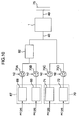
- the semiconductor production plant comprises a semiconductor production apparatus and a discharged gas treating apparatus for treating the discharged gas from the semiconductor production apparatus.
- the semiconductor production apparatus is provided with, for example, an etching apparatus 67 with etching chambers 68 and 69 and an etching apparatus 70 with etching chambers 71 and 72.
- a PFC treating apparatus 1 for treating PFC-containing discharged gas from etching chambers 68, 69, 71 and 72 is used.
- Gas discharge pipes 74A, 74B, 74C and 74D connected to the etching chambers 68, 69, 71 and 72, respectively, are put into one piping 40.
- the PFC treating apparatus 1 is connected to a piping 40 on one hand, and to a discharged gas duct 75 through a piping 49 on the other hand.
- Vacuum pumps 73A, 73B, 73C and 73D are provided in the gas discharge pipes 74A, 74B, 74C and 74D, respectively.
- PFC gas as an etching gas is fed to the etching chambers 68, 69, 71 and 72, each in a vacuum state, respectively.
- the PFC gas is brought into a plasma state to conduct etching treatments of wafers as semiconductor materials.
- a portion (10-30%) of the PFC gas fed to the etching chambers 68, 69, 71 and 72 is consumed by the etching treatments in the etching chambers.
- the vacuum pumps 73A, 73B, 73C and 73D discharged gases from the etching chambers 68, 69, 71 and 72 are passed through the gas discharge pipes 74A, 74B, 74C and 74D, respectively, joined into the piping 40 and fed to the PFC treating apparatus 1.
- the discharged gas contains PFC gas not consumed in the etching chambers 68, 69, 71 and 72. Still furthermore, the discharged gas contains HF secondarily generated from the PFC gas in the etching chambers, SiF 4 , etc. generated by etching the wafers.
- N 2 gas is fed to the bearings of the vacuum pumps. That is, the PFC concentration of the discharged gas led to PFC treating apparatus 1 is approximately 0.5%.
- the PFC gas is decomposed in the PFC treating apparatus 1.
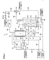
- a PFC treating apparatus according to one preferable embodiment of the present invention will be described below, referring to Fig. 1 .
- the catalyst cartridge 3 has a catalyst bed packed with a catalyst within it.
- the catalyst for use in the catalyst bed is an alumina-based catalyst containg 80% Al 2 O 3 and 20% NiO.
- the heating space 5 is provided upstream of the catalyst cartridge 3.
- a heater 4 is provided on the outside of the reactor 2 so as to surround the heating space 5.
- the cooling chamber 6 connected to the reactor 2 has a spray 7 within it and is positioned below the catalyst cartridge 3.
- a piping 42 connects the spray column 10 to the heating space 5.
- a piping 43 for feeding water (or steam) and a piping 44 for feeding air are each connected to the heating space 5.
- the annular float seat 58 is provided at the lower end of the inside wall of the piping 57.
- the float stopper 60 of a coarse wire net is provided at a position above the float seat 58 within the piping 57.
- the float 59 is provided between the float seat 58 and the float stopper 60.
- a discharged water piping 46 with a discharged water pump 80 is connected to the bottom of the discharged water tank 12.
- a piping 66 is connected to the discharged water piping 46 at a position downstream of the discharged water pump 80 and is further connected to the space above the packed bed 9 in the inlet packed column 8.
- a piping 57 connected to the bottom of the inlet packed column 8, i.e. below the packed bed 9 in the inlet packed column 9, is inserted into the discharged water tank 12.
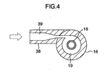
- the cyclone 16 has a lower compartment 19 and an upper compartment 20, both being partitioned by a partition wall 17, within it.
- a discharged gas feed member 38 extends in the tangential direction to the inside wall of the lower compartment 19.
- the flow passage 39 in the discharged gas feed member 38 is tapered toward the lower compartment 19.
- a piping 47 connected to the top of the discharged gas washing column 13 is connected to the discharged gas feed member 38.
- the passage 18 penetrating through the partition wall 17 connects the lower compartment 19 to the upper compartment 20.
- the drain outlet 23 formed at the bottom of the lower compartment 19 is connected to a drain piping 53, which is connected to the dicharged water tank 12.
- the drain outlet 22 formed in the upper compartment 20 is connected to the discharged water tank 12 through a drain piping 54.
- the ejector 24 comprises an ejector body 25, an injection nozzle 27 and an ejection nozzle 34.
- the ejector body 25 has an internal space 26 within it.
- the injection nozzle 27 has a nozzle member 28.
- the injection member 29 is screwed into the tip end part of the nozzle member 28.
- An injection orifice 30, about 2 mm in inner diameter, is formed in the injection member 29.
- the injection member 29 is made of highly corrosion-resistant and highly durable metal or ceramic.
- the ejection nozzle 34 has an ejection passage 35 within it.
- the injection nozzle 27 is provided against one end of the ejector body 25 through a packing 76.
- the tip end of the nozzle member 28 of the injection nozzle 27 is inserted into the ejector body 25 and is positioned in the internal space 26.
- the injection orifice 30 is connected to a flow passage 31 formed in the nozzle member 28 and to the internal spacing 26.
- the ejection nozzle 34 is provided against another end of the ejector body 25 through a packing 37.
- the ejection passage 35 of the ejection nozzle 34 is counterposed to the injection member 29 screwed in the nozzle member 28.
- the inlet of the ejection passage 35 is connected to the internal space 26.
- the ejection passage 35 has a throat region 77 with a minimum passage cross-sectional area within it.
- the cross-sectional area of the ejection passage 35 increases from the throat region 77 toward the inlet and also from the throat region 77 toward the ejector outlet 78.
- the degree of the latter increase in the passage cross-sectional area is smaller than the degree of the former increase.
- a pressing plate 32 with a flow inlet 33 is counterposed to the injection nozzle 27 through the packing 36.
- the pressing plate 32, the injection nozzle 27, the ejector body 25 and the ejection nozzle 34 are arranged in this order and are secured by bolts 79A and nuts 79B.
- Other members than the pressing plate 32 and the injection member 29 of the injection nozzle 27, e.g. the ejector body 25 and the ejection nozzle 34, are made of highly corrosion-resistant plastic, for example of vinyl chloride resin (or fluororesin, etc.).
- a piping 48 provided on the ejector body 25 is connected to the discharge outlet 21 formed at the top of the upper compartment 20 of the cyclone 16.
- the piping 48 is also connected to the internal space in the ejector body 25.
- the piping 49, connected to the discharged gas duct 75, is connected to the ejector outlet 78 of the ejection nozzle 34.
- a condensate drain piping 55 connected to piping 49 is connected to the discharged water tank 12.
- a water feed pipe 50 is connected to the spray 15.
- a water feed pipe 51 is connected to the spray 11.
- a water feed pipe 52 connected to the spray 7.
- the water feed pipes 51 and 52 are connected to the water feed pipe 50.
- a compressed air feeder 81 is fixed to the pressing plate 32.
- the compressed air feeder 81 comprises an air feed pipe 56, a pressure central valve 63 and an air feed valve 64.
- the air feed pipe 56 is connected to the pressing plate 32 and communicates with the flow inlet 33.
- a pressure control valve 63 is provided in the air feed pipe 56, where an air feed valve 64 is provided in the air feed pipe 56 at a position upstream of the pressure control valve 63.
- the air feed pipe 56 is connected to a compressor, though not shown in the drawings.
- Numeral 65 is a pressure switch (P) for safety interlock.
- PFC contained in the discharged gas to be fed to the PFC treating apparatus depends on the kinds of semiconductors produced in semiconductor production apparatuses or semiconductor plants.
- the production of wafers as a basis material for semiconductors involves cases of using a single PFC and a plurality of PFCs.
- the case of using SF 6 and C 2 F 6 as PFC in the semiconductor production is explained.
- Discharged gas containing SF 6 and C 2 F 6 as PFC, SiF 4 and HF from etching chambers 68, 69, 71 and 72 is fed to the inlet packed column 8 of a silicon removing apparatus through the piping 40 by driving vacuum pumps 73A, 73B, 73C and 73D.
- the discharged gas ascends through the packed bed 9 and is led to the spray column 10 of the silicon removing apparatus through the piping 41.
- Fresh water fed through the water feed pipe 51 is fed into the spray column 10 through the spray 11.
- the sprayed water is discharged into the piping 41 and led to the inlet packed column 8.
- Discharged water in the discharged water tank 12 is fed to the inlet packed column 8 through the discharged water piping 46 and piping 66 by driving the discharged water pump 80.
- the discharged water and the sprayed water descend through the packed bed 9.
- SiF 4 contained in the discharged gas undergoes reaction of the following reaction equation (4) through contact with water (discharged water and water sprayed in spray column 10) in the inlet packed column 8 and is decomposed to SiO 2 and HF: SiF 4 + 2H 2 O ⁇ SiO 2 + 4HF (4)
- HF contained in the discharged gas fed to the inlet packed column 8 and HF formed by the reaction of the reaction equation (4) are absorbed into water in the inlet packed column 8 and removed from the discharged gas.
- SiO 2 as a solid is also washed away by the washing water.
- the packed bed 9 acts to increase the contact efficiency between the ascending discharged gas and the descending washing water and increase the reaction efficiency of the reaction equation (4) and the absorption efficiency of HF into water.
- Water containing SiO 2 and absorbed HF is led to the discharged water tank 12 below the inlet packed column 8 through the piping 57.
- Other impurities contained in the discharged gas are also removed by water in the inlet packed column 8 and the spray column 10.
- the discharged gas containing SF 6 and C 2 F 6 discharged into the piping 42 from the spray column 10 is fed to the heated space 5 of the reactor 2 at a flow rate of 60 l/min.
- the discharged gas contains neither HF nor SiF 4 nor SiO 2 formed by the reaction of the reaction equation (1).
- Water (or steam) is fed through the piping 43 to the heated space 5, and air is fed thereto thereto through the piping 44.
- the decomposition reaction of PFC by a catalytic action is hydrolysis, and thus the necessary water (or steam) for the reaction is fed thereto.
- the discharged gas is heated, together with the water and the air, to a temperature of 750°C, at which decomposition of SF 6 and C 2 F 6 by the catalytic action starts, by the heater 4.
- the heating temperature is about 650 to about 750°C.
- Water turns to steam.
- the discharged gas containing steam, air, SF 6 and C 2 F 6 heated to 750° C is fed to the catalyst cartridge 3.
- reaction equation (2) and the reaction of the following reaction equation (5) of SF 6 and C 2 F 6 with H 2 O are promoted by the action of an alumina-based catalyst in the catalyst cartridge 3 to decompose SF 6 to SO 3 and HF and C 2 F 6 to CO 2 and HF: SF 6 + 3H 2 O ⁇ SO 3 + 6HF (2) C 2 F 6 + 3H 2 O + air (O 2 ) ⁇ 2CO 2 + 6HF (5)
- reaction equations (2) and (5) take place in the presence of steam.
- SF 6 and C 2 F 6 are 100% decomposed.
- harmful CO is formed by reaction of C 2 F 6 with H 2 O.
- oxygen contained in the air converts CO to harmless CO 2 , and thus no CO is generated as shown by the reaction equation (5).
- Oxygen may be fed thereto in place of air.
- Discharged gas containing SO 3 , CO 2 and HF as decomposition gases of SF 6 and C 2 F 6 is fed to the cooling chamber 6 from the catalyst cartridge 3.
- Water fed through the water feed pipe 52 is sprayed from the spray 7 into the cooling chamber 6.
- the discharged gas is cooled through contact with the sprayed water, so the discharged gas temperature is lowered to 100°C or lower, whereby apparatuses at the positions downstream of the reactor 2 (cooling chamber 6, discharged gas washing column 13, cyclone 16 and ejector 24) and pipings connecting one apparatus to another (pipings 45, 47, 48 and 49, discharged water piping 46, drain pipings 53 and 54 and condensate drain piping 55) can be made of vinyl chloride resin (or fluoro-resin, etc.) as highly corrosion-resistant plastics.
- Pipings 57 and 66 can be also made of vinyl chloride resin.
- a portion of HF contained in the discharged gas is absorbed into the sprayed water.
- the sprayed water and the discharged gas are led to the space above the liquid level 61 in the discharged water tank 12 from the cooling chamber 6 through the piping 45 (see Fig. 7 ).
- Discharged water is stored in discharged water tank 12 temporarily.
- the discharged water pump 80 By driving the discharged water pump 80, the water in discharged water tank 12 is discharged into the discharged water piping 46 to a discharged water treatment plant (not shown in the drawing) near the PFC treating apparatus.
- the water is pushed out of the piping 57 by the discharged gas to establish a discharged gas atmosphere.
- the float 59 fails to maintain floating in the piping 57 in such a discharged gas atmosphere and falls onto the float seat 58 to close the open end.
- the flow of the discharged gas from the inlet packed column 8 into the piping 57 is stopped.
- Such a discharged gas containing decomposition gases is led to the discharged gas washing column 13 from the discharged water tank 12.
- Water fed through the water feed pipe 50 is sprayed by the spray 15.
- the sprayed water descends through the packed bed 14 to fall into the discharged water tank 12.
- the discharged gas ascends through the packed bed 14.
- SO 3 and HF as acid gases contained in the discharged gas are absorbed into the sprayed water and separated from the discharged gas.
- SO 3 mists SO 3 mists
- An aqueous alkaline solution aqueous NaOH solution or aqueous KOH solution
- the discharged gas is fed to the lower compartment 19 of the cyclone 16 through the flow passage 39 and descends while whirling around the passage 18.
- Acid gas mists contained in the discharged gas are separated from the discharged gas by whirling of the discharged gas and blown off outwardly to attach to the side walls of the lower compartment 19.
- the attached mists flow down along the side walls toward the bottom of the lower compartment 19.
- the separated acid gas mists are discharged into the discharged water tank 12 from the drain outlet 23 through the drain piping 53.
- the whirling stream of the discharged gas in the lower compartment 19 ascends through the passage 18, while whirling, and reaches the upper compartment 20.
- the acid gas mists entrained in the discharged gas are separated from the discharged gas and flow downward along the side walls of the upper compartment 20.
- the separated acid mists are discharged into the discharged water tank 12 through the drain outlet 22 and the drain piping 54.
- the discharged gas with considerably reduced content of acid gas mists is discharged into the piping 48 from the discharge outlet 21 and then led to the ejector 24.
- Compressed air which is compressed by a compressor (not shown in the drawings), is fed to the ejector 24 through an air feed pipe 56 by opening the air feed valve 64.
- the compressed air is a driving gas for the ejector 24.
- the pressure of the compressed air is controlled to a set pressure by adjusting the opening degree of the pressure control valve 63.
- the compressed air is fed to the ejector 24 at substantially the same flow rate as that of the discharged gas to be fed to the reactor 2, i.e. at about 60 to about 80 l/min and at a pressure of about 0.1 MPa.
- N 2 gas or He gas may be used as a driving gas in place of the compressed air.
- the compressed air is fed to the flow passage 31 of the nozzle member 28 from the flow inlet 33 and injected from the injection orifice 30 toward the ejection passage 35 of the ejection nozzle 34 at a sonic or supersonic speed.
- the injection stream of compressed air from the injection orifice 30 generates a negative pressure in the throat region 77 or its neighborhood of the ejection passage 35.
- the discharged gas in the piping 48 is sucked into the ejection passage 35 through the internal space 26 and discharged into the piping 49.
- the discharged gas is led to the discharged gas duct 75 through the piping 49 ( Fig. 2 ).
- Condensate contained in the discharged gas from the ejector 24 is led to the discharged water tank 12 through the condensate drain piping 55.
- the cooling chamber 6, the discharged water tank 12 and the discharged gas washing column 13 are kept in a negative pressure state to prevent SO 3 , HF, etc. contained in the discharged gas from leakage to the outside.
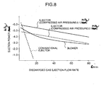
- the ejector 24 used in this embodiment has such ejection characteristics as shown in Fig. 8 by the full line. Even if the ejection flow rate of the discharged gas from the ejector 24 is increased, the degree of lowering of the suction power of the ejector 24 can be kept small.
- the ejector 24 has been developed by the present inventors.
- the ejector 24 has substantially equivalent ejection characteristics to those of the blower (as shown in Fig. 8 by the dot and dash line). Even if the pressure of the driving compressed air to be fed to the ejector 24 is changed to e.g. 0.1 MPa and 0.12 MPa, respectively, the degree of lowering of the suction power is substantially not changed against the increasing ejection flow rate of discharged gas.
- the ejector 24 can have a large ejection flow rate of discharged gas.
- the discharged gas suction power increases proportionally to increasing pressure of driving compressed air.
- the pressure switch 65 detects the pressure in the air feed pipe 56 at the position downstream of the pressure control valve 63 to close the air feed valve 64 when the pressure exceeds the set pressure and stops the compresser (not shown in the drawings).
- the discharged gas led to the ejector 24 contains a small amount of acid gas mists, but since the ejector 24 is made of a highly corrosion-resistant plastic, there is no fear of corrosion, even if it is brought into contact with the acid gas mists.
- any corrosion due to decomposition gas does not take place in the ejector 24 as a decomposition gas-containing discharged gas ejecting apparatus, and thus, maintenance working such as inspection, part replacement, etc. of the discharged gas ejecting apparatus (apparatus for injecting a gas to such another gas) is substantially not required. That is, the frequency of maintenance inspection is considerably lower than in the case of using a blower, and the continuous operation rate of the PFC treating apparatus 1 is considerably improved.
- the injection member 29 with the injection orifice 30 for ejecting the discharged gas at a sonic or supersonic speed is made of a highly corrosion-resistant, highly durable ceramic, wearing due to sonic speed-discharged gas is considerably less, contributing to lowering of the frequency of maintenance inspection of the ejector 24.
- the ejector 24 can fully perform continuous long-term operation.
- the use of the cyclone 16 as a mist separating apparatus reduces the amount of acid gas mists to the discharged gas duct 75 through the ejector 24.
- the amount of mists condensed in the discharged gas duct 75 can be reduced, considerably reducing corrosion of the discharged gas duct 75.
- the reduction in the amount of mists results in a further prolongation of the life of the ejector 24.
- the discharged water tank 12 is at the lowest position and thus the water discharged from the inlet packed column 8 and the spray column 10, sprayed water from the cooling chamber 6 and the discharged gas washing column 13 and drain water separated in the cyclone 16 flow into the discharged water tank 12 by gravity.
- pumps for transferring these kinds of water to the discharged water tank 12 are not required, thereby making the structure of the PFC treating apparatus 1 more compact.
- the PFC treating apparatus 1 of this embodiment can decompose also any other PFC than SF 6 and C 2 F 6 .
- An SF 6 decomposition treatment test was carried out in the PFC treating apparatus 1 shown in Fig. 1 , using a simulation gas containing SF 6 .
- the simulation gas was prepared by diluting SF 6 with nitrogen gas to contain 0.5% SF 6 .
- the simulation gas was fed to the reactor 2 of the PFC treating apparatus 1 at a flow rate of 60 l/min. Air and water were also fed to the reactor 2 at 15 l/min. and 20 ml/min, respectively.
- the simulation gas containing water and air was heated to 750°C by an electric heater in the heating space 5. Then, the simulation gas was fed to the catalyst cartridge 3 and decomposed.
- the catalyst packed in the catalyst cartridge 3 was a NiO and Al 2 O 3 -containing catalyst.
- SF 6 was treated at a space velocity of the simulation gas to the catalyst of 1,000/h.
- Gas containing SF 6 decomposition gas discharged from the reactor 2 was cooled in the cooling chamber 6 and then led to the cyclone 16 at a flow velocity of about 20 m/s through the discharged gas washing column 14.
- Acid gas mists separated and removed by the cyclone 16 were discharged into the dicharged water tank 12 from the bottom of the cyclone 16 through the drain piping 53.
- Gas discharged from the cyclone 16 was sucked by the ejector 24 driven by compressed air at 0.1 MPa. The flow rate of compressed air to the ejector 24 was about 70 l/min.
- the SO 3 concentration of the gas at a position upstream of the cyclone 16 (in piping 47) and at a position downstream thereof (in piping 48) was measured to determine the mist removal efficiency of the cyclone 16. Since SO 3 mists are formed by absorption of water molecules around SO 3 as nuclei, the mist removal efficiency of the cyclone 16 can be calculated by the ratio of the SO 3 concentration in the piping 48 to that in the piping 47.
- the SO 3 concentration was calculated by subtracting the gaschromatographically measured SO 2 concentration from the SOx concentration measured by a liquid trapping method. As a result, the SO 3 concentration was 1,400 ppm at the position upstream of the cyclone 16, whereas it was 280 ppm after the cyclone 16. That is, 80% of the mists were removed by the cyclone 16.
- mist particle size distribution was measured at the outlet of the cyclone 16. Mists contained in the gas discharged from the cyclone 16 had particle sizes substantially smaller than 1 ⁇ m. Mists having particle sizes of 1 ⁇ m or more were removed by the cyclone 16. After the treating operation for a predetermined time, the ejector 24 was dismantled, and it was found by inspection that no corrosion took place at the interior of the ejector 24, and no condensate was observed in the piping 49 at the outlet side of the ejector 24.
- a NF 3 -containing simulation gas was used to conduct the same test as in the case of using the SF 6 -containing simulation gas.
- Nitric acid mists were smaller in particle size than sulfuric acid mists, and accordingly, the removal efficiency of the mist removing apparatus was as low as 20-30%, but no corrosion, etc. were found to take place in the ejector as in the test with the SF 6 -containing simulation gas.
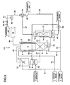
- a PFC treating apparatus 1A not forming part of the present invention will be described below, referring to Fig. 9 , where the same members as in the embodiment of Fig. 1 are identified by the same reference numerals.
- the PFC treating apparatus 1A is different from the PFC treating apparatus 1 of the invention only in the omission of the cyclone 16 of Fig. 1 .
- the piping 47 connects the top of the discharged gas washing column 13 directly to the internal space 26 of the ejector 24. In this apparatus, the discharged gas from the discharged gas washing column 13 is sucked into the piping 47 by the suction of the ejector 24 and discharged into the piping 49.
- the structure is more simplified than the PFC treating apparatus 1 due to the omission of the cyclone 16.
- This apparatus may preferably be applied to the case that the concentration of PFC to the PFC treating apparatus 1A is low, and the amount of acid gas mists entrained in the discharged gas from the discharged gas washing column 13 is small.
- the discharged gas washing column 13 may be omitted in the embodiment of Fig. 1 ; in such an apparatus not forming part of the present invention, the piping 47 connected to the cyclone 16 is connected directly to the space above the liquid level 61 in the discharged water tank 12.
- wafers with metallic wirings are etched in some cases, For example, in the semiconductor production plant shown in Fig. 10 , wafers with metallic wirings are etched in etching chambers 68 and 69 of the etching apparatus 67. A large amount of attachable by-products originating from the metallic wirings are generated by the etching. Residual PFC containing the by-products, HF and SiF 6 , are discharged from the etching chambers 68 and 69 and fed, together with N 2 gas fed to vacuum pumps 73A and 73B, to a pretreating apparatus 82 packed with activated carbon. The attachable by-products are removed by the pretreating apparatus 82. The discharged gas from the pretreating apparatus 82 is led to the PFC treating apparatus 1 through the piping 40. By removing the attachable by-products by the pretreating apparatus 82 in this manner, PFC can be efficiently decomposed by the catalyst cartridge 3.
- a chlorine gas, a hydrogen chloride gas or hydrogen bromide (HBr) gas is used as etching gas besides the PFC gas, where the chlorine gas, the hydrogen chloride gas or the hydrogen bromide gas is mixed with the PFC gas and fed to the etching chambers.
- the chlorine gas, the hydrogen chloride gas or the hydrogen bromide gas is fed to the etching chambers after the etching by the PFC gas has been finished.
- the etching treatment by the chlorine gas, the hydrogen chloride gas or the hydrogen bromide gas is carried out before the etching treatment by the PFC gas, where the feeding of the chlorine gas, the hydrogen chloride gas or the hydrogen bromide gas to the etching chambers is carried out before the feeding of the PFC gas.
- the chlorine gas, the hydrogen chloride gas and the hydrogen bromide gas are also acid gases as HF.
- a simulation gas containing N 2 and 1% Cl 2 was fed to the PFC treating apparatus 1.
- the Cl 2 gas was passed through the inlet packed column 8 and spray column 10 to reach the reactor 2 through the piping 42.
- the catalyst temperature was 750°C (simulation gas flow rate: 60 l/min).
- the Cl 2 gas was substantially not removed in the inlet packed column 8 and the spray column 10. Air and reaction water were fed to the reactor 2 at 10 l/min and 15 ml/min, respectively.
- the Cl 2 gas is oxidized by the catalyst in the catalyst cartridge 3 to turn it to an HCl gas by the reaction shown by the following reaction equation (6) : 2Cl 2 + 2H 2 O ⁇ 2HCl + O 2 (6).
- the HCl gas is easily soluble in water and thus was absorbed into sprayed water in the discharged gas washing column 13 and removed from the simulation gas.
- the simulation gas was discharged from discharged gas washing column 13 at a Cl 2 concentration of 100 ppm. That is, 99% of Cl 2 were removed thereby. No HCl was detected in the discharged simulation gas. No corrosion by the Cl 2 gas was found on the ejector 24.
Landscapes
- Engineering & Computer Science (AREA)
- Chemical & Material Sciences (AREA)
- Environmental & Geological Engineering (AREA)
- General Chemical & Material Sciences (AREA)
- Biomedical Technology (AREA)
- Analytical Chemistry (AREA)
- Health & Medical Sciences (AREA)
- Oil, Petroleum & Natural Gas (AREA)
- Chemical Kinetics & Catalysis (AREA)
- Treating Waste Gases (AREA)
- Exhaust Gas Treatment By Means Of Catalyst (AREA)
- Gas Separation By Absorption (AREA)
- Drying Of Semiconductors (AREA)
Claims (9)
- Verfahren zur Behandlung von in einem Gas enthaltenen Perfluorverbindungen, mit den folgenden Schritten:(A) Zerlegen der in dem Gas enthaltenen Perfluorverbindungen in ein Sauergase enthaltendes Gas,(B) Entfernen der Sauergase aus dem aus Schritt (A) abgegebenen Gas durch Gaswaschen mit Wasser oder einer wässrigen Alkalilösung in einem Gaswaschturm (13), der einen Sprühnebel (15) und einen Abgabewassertank (12) umfasst, und(C) Abtrennen des säurehaltigen Nebels, der in dem aus dem Gaswaschturm (13) abgegebenen Gas enthalten ist,wobei der Gaswaschturm (13) und der Abgabewassertank (12) durch Absaugen des aus dem Gaswaschturm (13) abgegebenen Gases durch ein Rohrleitungssystem (47), das mit dem oberen Ende des Gaswaschturms (13) verbunden ist, und ein Rohrleitungssystem (48) mittels einer Ausstoßvorrichtung (24) unter negativen Druck gehalten werden,
dadurch gekennzeichnet, dass- in Schritt (C) mittels eines Zyklons (16), der eine obere Kammer (20) und eine untere Kammer (19) umfasst, Nebel abgetrennt werden, wobei dessen Einspeisungselement (38) durch das Rohrleitungssystem (47) mit dem oberen Ende des Gaswaschturms (13) verbunden ist und dessen Gasabgabeöffnung (21) durch das Rohrleitungssystem (48) mit der Ausstoßvorrichtung (24) verbunden ist,- wobei• der Nebel, der von dem Gas abgetrennt und aus der Ausflussöffnung (23) des Zyklons (16) abgegeben wurde, die im Boden von dessen unterer Kammer (19) vorgesehen ist, durch ein Abgaberohrleitungssystem (53) in den Tank (12) abgegeben wird, und• der verwendete Zyklon (16) eine weitere Ausflussöffnung (22) umfasst, die in der oberen Kammer (20) vorgesehen ist, wo in dem abgegebenen Gas mitgeführte Nebel abgetrennt und durch die weitere Ausflussöffnung (22) und ein Ausflussrohrleitungssystem (54) in den Tank (12) abgegeben werden. - Verfahren nach Anspruch 1, dadurch gekennzeichnet, dass Kondensat, das in dem Gas enthalten ist, welches aus der Ausstoßvorrichtung (24) abgegeben wird, durch ein Kondensatausflussrohrleitungssystem (55) zum Tank (12) geführt wird.
- Verfahren nach Anspruch 1 oder 2, dadurch gekennzeichnet, dass die Perfluorverbindungen in Schritt (A) katalytisch zerlegt werden.
- Verfahren nach irgendeinem der Ansprüche 1 bis 3, dadurch gekennzeichnet, dass die Perfluorverbindungen in einem Gas enthalten sind, das von einer Halbleiteranlage abgegeben wird.
- Vorrichtung (1) zur Behandlung von Perfluorverbindungen, die in einem in sie eingespeisten Gas enthalten sind, mit:- einer Perfluorverbindungen zerlegenden Vorrichtung (2, 3) zum Zerlegen der in dem Gas enthaltenen Perfluorverbindungen,- einem Gaswaschturm (13) zum Entfernen von Sauergasen aus dem Gas, die aus der Zerlegung der Perfluorverbindungen in der Perfluorverbindungen zerlegenden Vorrichtung (2, 3) stammen, mittels eines Sprühnebels (15) aus Wasser oder einer wässrigen Alkalilösung,- einem unter dem Gaswaschturm (13) vorgesehenen Tank (12) zum Aufnehmen des Wassers oder der wässrigen Alkalilösung, das/die zum Gaswaschen verwendet wird,- einer Nebelabtrenneinrichtung (16), die stromabwärts des Sprühnebels (15) vorgesehen ist,und
einer Ausstoßvorrichtung (25) zum Halten des Gaswaschturms (13) und des Tanks (12) unter negativem Druck durch Absaugen des aus dem Gaswaschturm (13) abgegebenen Gases durch ein Rohrleitungssystem (47), das mit dem oberen Ende des Gaswaschturms (13) verbunden ist,
und ein Rohrleitungssystem (48),
dadurch gekennzeichnet, dass- die Nebelabtrenneinrichtungen ein Zyklon (16) sind, der eine obere Kammer (20) und eine untere Kammer (19) umfasst, wobei dessen Einspeisungselement (38) durch das Rohrleitungssystem (47) mit dem oberen Ende des Gaswaschturms (13) verbunden ist und dessen Gasabgabeöffnung (21) durch das Rohrleitungssystem (48) mit der Ausstoßvorrichtung (24) verbunden ist,- wobei• die Ausflussöffnung (23) des Zyklons (16), die im Boden von dessen unterer Kammer (19) vorgesehen ist, durch ein Abgaberohrleitungssystem (53) mit dem Tank (12) verbunden ist, und• der Zyklon (16) eine weitere Ausflussöffnung (22) umfasst, die in der oberen Kammer (20) vorgesehen ist, um Nebel, die in dem abgegebenen Gas mitgeführt und in der oberen Kammer (20) abgetrennt werden, abzugeben, wobei die weitere Ausflussöffnung (22) durch ein Ausflussrohrleitungssystem (54) mit dem Tank (12) verbunden ist. - Vorrichtung nach Anspruch 5, dadurch gekennzeichnet, dass die Ausstoßvorrichtung (24) mit einer Abgabegasleitung (75) durch ein Rohrleitungssystem (49) verbunden ist, das mit einem Kondensatausflussrohrleitungssystem (55) verbunden ist, welches mit dem Tank (12) verbunden ist, um Kondensat, das in dem aus der Ausstoßvorrichtung (24) abgegebenen Gas enthalten ist, zum Tank (12) zu führen.
- Vorrichtung nach Anspruch 5 oder 6, dadurch gekennzeichnet, dass die Perfluorverbindungen zerlegende Vorrichtung (2, 3) ein Reaktor (2) ist, der einen gepackten Katalysator (3) und eine Heizvorrichtung (4) für die thermische katalytische Zerlegung der Perfluorverbindungen umfasst.
- Vorrichtung nach Anspruch 7, dadurch gekennzeichnet, dass der Katalysator ein Aluminiumoxid und weiterhin ein Oxid eines Metalls enthält, das aus Zn, Ni, Ti, Fe, Sn, Co, Zr, Ce, Si und Pt ausgewählt ist.
- Vorrichtung nach irgendeinem der Ansprüche 5 bis 8, dadurch gekennzeichnet, dass Einrichtungen zum Stoppen der Einspeisung von Antriebsgas in die Ausstoßvorrichtung (24), wenn der Druck des Antriebsgases zur Ausstoßvorrichtung (24) einen eingestellten Druck überschreitet, vorgesehen sind.
Applications Claiming Priority (2)
| Application Number | Priority Date | Filing Date | Title |
|---|---|---|---|
| JP2001075241A JP4211227B2 (ja) | 2001-03-16 | 2001-03-16 | 過弗化物の処理方法及びその処理装置 |
| JP2001075241 | 2001-03-16 |
Publications (2)
| Publication Number | Publication Date |
|---|---|
| EP1240937A1 EP1240937A1 (de) | 2002-09-18 |
| EP1240937B1 true EP1240937B1 (de) | 2009-11-18 |
Family
ID=18932352
Family Applications (1)
| Application Number | Title | Priority Date | Filing Date |
|---|---|---|---|
| EP01119737A Expired - Lifetime EP1240937B1 (de) | 2001-03-16 | 2001-08-27 | Verfahren und Vorrichtung zur Beseitigung von Perfluorverbindungen |
Country Status (6)
| Country | Link |
|---|---|
| US (2) | US20020131912A1 (de) |
| EP (1) | EP1240937B1 (de) |
| JP (1) | JP4211227B2 (de) |
| KR (1) | KR100806011B1 (de) |
| DE (1) | DE60140514D1 (de) |
| TW (1) | TWI292721B (de) |
Families Citing this family (33)
| Publication number | Priority date | Publication date | Assignee | Title |
|---|---|---|---|---|
| US20010001652A1 (en) * | 1997-01-14 | 2001-05-24 | Shuichi Kanno | Process for treating flourine compound-containing gas |
| JP3994605B2 (ja) * | 1999-11-26 | 2007-10-24 | 株式会社日立製作所 | Pfcガスの処理方法及び処理装置 |
| US7569193B2 (en) | 2003-12-19 | 2009-08-04 | Applied Materials, Inc. | Apparatus and method for controlled combustion of gaseous pollutants |
| JP4218618B2 (ja) * | 2004-09-10 | 2009-02-04 | 株式会社日立製作所 | 排ガス分解処理装置 |
| US7138551B2 (en) * | 2004-11-05 | 2006-11-21 | E. I. Du Pont De Nemours And Company | Purification of fluorinated alcohols |
| US7736599B2 (en) | 2004-11-12 | 2010-06-15 | Applied Materials, Inc. | Reactor design to reduce particle deposition during process abatement |
| KR20080021697A (ko) * | 2005-06-13 | 2008-03-07 | 어플라이드 머티어리얼스, 인코포레이티드 | 폐가스 경감 방법 및 장치 |
| JP4966521B2 (ja) * | 2005-07-22 | 2012-07-04 | 昭和電工株式会社 | 過弗化物含有排ガスの処理方法及び処理装置 |
| JP5102217B2 (ja) | 2005-10-31 | 2012-12-19 | アプライド マテリアルズ インコーポレイテッド | プロセス削減反応器 |
| WO2007095150A2 (en) * | 2006-02-11 | 2007-08-23 | Applied Materials, Inc. | Methods and apparatus for pfc abatement using a cdo chamber |
| KR100743399B1 (ko) * | 2006-06-15 | 2007-07-27 | 주식회사 에코프로 | 반도체 제조공정에서 발생하는 염소가스와 과불화물의처리장치 |
| TWI355964B (en) * | 2007-12-05 | 2012-01-11 | Ind Tech Res Inst | Method for catalytic treating perfluorocompound ga |
| US8673212B2 (en) * | 2010-05-28 | 2014-03-18 | Steris Corporation | Apparatus to decontaminate equipment containing internal channels |
| JP5886976B2 (ja) | 2012-10-18 | 2016-03-16 | 日立建機株式会社 | 作業機械 |
| US9051196B2 (en) * | 2013-03-15 | 2015-06-09 | Clack Corporation | Baffle plate for a water treatment device |
| KR101514801B1 (ko) * | 2013-06-25 | 2015-04-24 | (주)파인텍 | 과불화화합물의 분리 및 재활용시스템 |
| US9259683B2 (en) | 2014-01-22 | 2016-02-16 | Micron Technology, Inc. | Methods and apparatus for treating fluorinated greenhouse gases in gas streams |
| KR101638325B1 (ko) | 2014-09-03 | 2016-07-12 | 노영석 | 분리막시스템과 스크러버가 일체로 이루어지는 과불화화합물 분리시스템 |
| US10375901B2 (en) | 2014-12-09 | 2019-08-13 | Mtd Products Inc | Blower/vacuum |
| US10065197B2 (en) * | 2016-07-12 | 2018-09-04 | John Richmond | Hydraulic particle separation apparatus for placer mining |
| KR101825825B1 (ko) * | 2016-08-02 | 2018-02-06 | 주식회사 에코프로 | 질소산화물, 염화불화탄소류, 수소염화불화탄소류, 수소불화탄소류 및 과불화화합물을 포함하는 복합 폐가스의 통합 처리 시스템 |
| CN111306559A (zh) * | 2017-07-07 | 2020-06-19 | 鉴锋国际股份有限公司 | 用于控制气体污染物分解氧化的装置及系统 |
| DK3680364T3 (da) * | 2017-09-07 | 2022-01-24 | De Nora Permelec Ltd | Elektrolyseindretning |
| CN107638794A (zh) * | 2017-10-18 | 2018-01-30 | 四川西丹孚能源科技有限公司 | 一种新型电解液废气零排放环保系统 |
| CN108295633B (zh) * | 2018-03-13 | 2023-09-05 | 中国华电科工集团有限公司 | 一种用于火电厂脱硫塔循环浆液冷却消白烟的装置和方法 |
| CN109107322A (zh) * | 2018-10-08 | 2019-01-01 | 绍兴市锐新环境设备有限公司 | 一种简单高效的烟雾净化器 |
| KR102332213B1 (ko) * | 2019-08-22 | 2021-12-01 | 한국전력공사 | 플라즈마를 이용한 고농도 육불화황(sf6)의 분해 및 후처리 시스템 |
| CN110585906A (zh) * | 2019-09-11 | 2019-12-20 | 肖涛 | 一种危废高温烟气处理工艺 |
| CN113247870B (zh) * | 2021-04-03 | 2022-05-10 | 中船(邯郸)派瑞特种气体股份有限公司 | 一种制备高纯三氟化氮气体的方法及装置 |
| EP4273093B1 (de) | 2022-01-29 | 2025-12-10 | Contemporary Amperex Technology Co., Limited | Verfahren zur herstellung von sulfurylfluorid |
| CN115557471B (zh) * | 2022-01-29 | 2024-02-20 | 宁德时代新能源科技股份有限公司 | 一种制备硫酰氟的方法及硫酰氟 |
| US12400879B2 (en) | 2022-02-25 | 2025-08-26 | Samsung Electronics Co., Ltd. | Gas treatment system and gas treatment method using the same |
| CN116672861A (zh) * | 2023-07-03 | 2023-09-01 | 红枫国领环保设备制造成都有限公司 | 一种实验室用酸雾及氯气处理系统及处理方法 |
Family Cites Families (19)
| Publication number | Priority date | Publication date | Assignee | Title |
|---|---|---|---|---|
| US4057404A (en) * | 1976-02-23 | 1977-11-08 | E. I. Du Pont De Nemours And Company | Method for separating immiscible fluids of different density |
| US4980090A (en) * | 1988-02-26 | 1990-12-25 | Manchak Frank | Process of isolating hazardous waste by centrifugal casting and product |
| JPH07284642A (ja) * | 1994-04-19 | 1995-10-31 | Hisao Kojima | ミキシングエレメント及びその製造方法 |
| US5785741A (en) * | 1995-07-17 | 1998-07-28 | L'air Liquide, Societe Anonyme Pour L'etude Et L'exploitation Des Procedes Georges, Claude | Process and system for separation and recovery of perfluorocompound gases |
| US6069291A (en) * | 1996-06-12 | 2000-05-30 | Guild Associates, Inc. | Catalytic process for the decomposition of perfluoroalkanes |
| IE80909B1 (en) * | 1996-06-14 | 1999-06-16 | Air Liquide | An improved process and system for separation and recovery of perfluorocompound gases |
| US20010001652A1 (en) * | 1997-01-14 | 2001-05-24 | Shuichi Kanno | Process for treating flourine compound-containing gas |
| JPH10286434A (ja) * | 1997-04-15 | 1998-10-27 | Ube Ind Ltd | フッ素含有化合物の分解方法 |
| EP1340533B1 (de) * | 1997-06-20 | 2010-06-16 | Hitachi, Ltd. | Verfahren, Katalysator und Vorrichtung zur Zersetzung fluorierter Verbindungen |
| JP3269456B2 (ja) | 1997-06-20 | 2002-03-25 | 株式会社日立製作所 | フッ素含有化合物の分解処理方法、触媒及び分解処理装置 |
| WO1999020374A1 (en) * | 1997-10-17 | 1999-04-29 | Ebara Corporation | Method and apparatus for processing exhaust gas of semiconductor fabrication |
| US8231851B2 (en) * | 1997-11-14 | 2012-07-31 | Hitachi, Ltd. | Method for processing perfluorocarbon, and apparatus therefor |
| JP3217034B2 (ja) | 1997-11-14 | 2001-10-09 | 株式会社日立製作所 | 過弗化物の処理方法及びその処理装置 |
| TW550112B (en) * | 1997-11-14 | 2003-09-01 | Hitachi Ltd | Method for processing perfluorocarbon, and apparatus therefor |
| US6126906A (en) * | 1998-06-18 | 2000-10-03 | Kanken Techno Co., Ltd. | Apparatus for removing harmful components in a semiconductor exhaust gas |
| US6630421B1 (en) * | 1999-04-28 | 2003-10-07 | Showa Denko Kabushiki Kaisha | Reactive agent and process for decomposing fluorine compounds and use thereof |
| JP3976459B2 (ja) * | 1999-11-18 | 2007-09-19 | 株式会社荏原製作所 | フッ素含有化合物を含む排ガスの処理方法及び装置 |
| JP2001293335A (ja) * | 2000-04-12 | 2001-10-23 | Ebara Corp | フッ素含有化合物を含む排ガスの処理方法 |
| JP4214717B2 (ja) * | 2002-05-31 | 2009-01-28 | 株式会社日立製作所 | 過弗化物処理装置 |
-
2001
- 2001-03-16 JP JP2001075241A patent/JP4211227B2/ja not_active Expired - Lifetime
- 2001-08-17 TW TW090120299A patent/TWI292721B/zh not_active IP Right Cessation
- 2001-08-27 EP EP01119737A patent/EP1240937B1/de not_active Expired - Lifetime
- 2001-08-27 DE DE60140514T patent/DE60140514D1/de not_active Expired - Lifetime
- 2001-08-29 US US09/940,984 patent/US20020131912A1/en not_active Abandoned
- 2001-08-29 KR KR1020010052337A patent/KR100806011B1/ko not_active Expired - Fee Related
-
2002
- 2002-03-06 US US10/090,817 patent/US7128882B2/en not_active Expired - Lifetime
Also Published As
| Publication number | Publication date |
|---|---|
| TWI292721B (de) | 2008-01-21 |
| KR20020074048A (ko) | 2002-09-28 |
| US20020131912A1 (en) | 2002-09-19 |
| EP1240937A1 (de) | 2002-09-18 |
| US20020131913A1 (en) | 2002-09-19 |
| US7128882B2 (en) | 2006-10-31 |
| JP4211227B2 (ja) | 2009-01-21 |
| DE60140514D1 (de) | 2009-12-31 |
| KR100806011B1 (ko) | 2008-02-26 |
| JP2002273172A (ja) | 2002-09-24 |
Similar Documents
| Publication | Publication Date | Title |
|---|---|---|
| US7128882B2 (en) | Method and apparatus for treating perfluorocompounds | |
| KR100847916B1 (ko) | 반도체 제조 시의 배출 가스를 산화 처리하기 위한 배기가스 스트림 처리 장치 및 방법 | |
| TW458803B (en) | Apparatus and method for controlled decomposition oxidation of gaseous pollutants | |
| US20020192129A1 (en) | Abatement of fluorine gas from effluent | |
| US20010048902A1 (en) | Treatment system for removing hazardous substances from a semiconductor process waste gas stream | |
| JP2001502604A (ja) | 半導体製造排気の酸化処理のための排気流処理システム | |
| US7060235B2 (en) | Method for processing perfluorocompounds exhaust | |
| US5743939A (en) | Waste gas processing apparatus and method for semiconductor fabricating equipment | |
| CN102179154A (zh) | 一种气体洗涤塔 | |
| JP5165861B2 (ja) | 過弗化物の処理方法及び処理装置 | |
| US7101425B2 (en) | Washer and method for purifying gases | |
| JP4594065B2 (ja) | 半導体製造プロセスからの排気ガスに含まれるフッ素化合物の処理装置及び処理方法 | |
| CN112138503B (zh) | 一种锂渣水解尾气处理装置 | |
| WO2018181771A1 (ja) | 排ガス処理装置及び排ガス処理方法 | |
| JP3862862B2 (ja) | 半導体製造排ガス除害機の火炎防止装置 | |
| JP5289668B2 (ja) | 湿式排煙脱硫装置 | |
| KR102041520B1 (ko) | 질소산화물 및 황산화물의 통합 처리 시스템 | |
| CN219023834U (zh) | 一种乙二醇废气接收罐 | |
| JP5004453B2 (ja) | 排ガスの処理方法及び処理装置 | |
| CN219804440U (zh) | 湿法烟气脱硫装置 | |
| CN212348690U (zh) | 氧化性气态等离子体发生装置及烟气治理装置 | |
| US20260115624A1 (en) | Gas purification system | |
| CN202036916U (zh) | 气体洗涤塔 | |
| CN112999842B (zh) | 一种微波诱导活性炭吸附蒸汽脱附硫化氢脱除装置 | |
| JP2008183563A (ja) | 気体中の異種物質の除去装置 |
Legal Events
| Date | Code | Title | Description |
|---|---|---|---|
| PUAI | Public reference made under article 153(3) epc to a published international application that has entered the european phase |
Free format text: ORIGINAL CODE: 0009012 |
|
| AK | Designated contracting states |
Kind code of ref document: A1 Designated state(s): AT BE CH CY DE DK ES FI FR GB GR IE IT LI LU MC NL PT SE TR |
|
| AX | Request for extension of the european patent |
Free format text: AL;LT;LV;MK;RO;SI |
|
| 17P | Request for examination filed |
Effective date: 20030117 |
|
| AKX | Designation fees paid |
Designated state(s): DE FR GB IT |
|
| 17Q | First examination report despatched |
Effective date: 20070618 |
|
| GRAP | Despatch of communication of intention to grant a patent |
Free format text: ORIGINAL CODE: EPIDOSNIGR1 |
|
| GRAS | Grant fee paid |
Free format text: ORIGINAL CODE: EPIDOSNIGR3 |
|
| RIN1 | Information on inventor provided before grant (corrected) |
Inventor name: TAMATA, SHIN,H Inventor name: KOUKUN, RI,H Inventor name: SHIBANO, YOSHIKI,H Inventor name: KANNO, SHUICHI,H Inventor name: IRIE, KAZUYOSHI,H |
|
| RAP1 | Party data changed (applicant data changed or rights of an application transferred) |
Owner name: HITACHI, LTD. |
|
| GRAA | (expected) grant |
Free format text: ORIGINAL CODE: 0009210 |
|
| GRAL | Information related to payment of fee for publishing/printing deleted |
Free format text: ORIGINAL CODE: EPIDOSDIGR3 |
|
| GRAS | Grant fee paid |
Free format text: ORIGINAL CODE: EPIDOSNIGR3 |
|
| AK | Designated contracting states |
Kind code of ref document: B1 Designated state(s): DE FR GB IT |
|
| REG | Reference to a national code |
Ref country code: GB Ref legal event code: FG4D |
|
| REF | Corresponds to: |
Ref document number: 60140514 Country of ref document: DE Date of ref document: 20091231 Kind code of ref document: P |
|
| PLBE | No opposition filed within time limit |
Free format text: ORIGINAL CODE: 0009261 |
|
| STAA | Information on the status of an ep patent application or granted ep patent |
Free format text: STATUS: NO OPPOSITION FILED WITHIN TIME LIMIT |
|
| 26N | No opposition filed |
Effective date: 20100819 |
|
| PGFP | Annual fee paid to national office [announced via postgrant information from national office to epo] |
Ref country code: GB Payment date: 20100617 Year of fee payment: 10 |
|
| GBPC | Gb: european patent ceased through non-payment of renewal fee |
Effective date: 20110827 |
|
| PG25 | Lapsed in a contracting state [announced via postgrant information from national office to epo] |
Ref country code: GB Free format text: LAPSE BECAUSE OF NON-PAYMENT OF DUE FEES Effective date: 20110827 |
|
| PGFP | Annual fee paid to national office [announced via postgrant information from national office to epo] |
Ref country code: FR Payment date: 20120823 Year of fee payment: 12 Ref country code: DE Payment date: 20120822 Year of fee payment: 12 Ref country code: IT Payment date: 20120813 Year of fee payment: 12 |
|
| REG | Reference to a national code |
Ref country code: DE Ref legal event code: R082 Ref document number: 60140514 Country of ref document: DE Representative=s name: MERH-IP MATIAS ERNY REICHL HOFFMANN, DE |
|
| REG | Reference to a national code |
Ref country code: DE Ref legal event code: R082 Ref document number: 60140514 Country of ref document: DE Representative=s name: MERH-IP MATIAS ERNY REICHL HOFFMANN, DE Effective date: 20130206 Ref country code: DE Ref legal event code: R081 Ref document number: 60140514 Country of ref document: DE Owner name: SHOWA DENKO K.K., JP Free format text: FORMER OWNER: HITACHI, LTD., TOKYO, JP Effective date: 20130206 |
|
| PG25 | Lapsed in a contracting state [announced via postgrant information from national office to epo] |
Ref country code: DE Free format text: LAPSE BECAUSE OF NON-PAYMENT OF DUE FEES Effective date: 20140301 |
|
| REG | Reference to a national code |
Ref country code: DE Ref legal event code: R119 Ref document number: 60140514 Country of ref document: DE Effective date: 20140301 |
|
| REG | Reference to a national code |
Ref country code: FR Ref legal event code: ST Effective date: 20140430 |
|
| PG25 | Lapsed in a contracting state [announced via postgrant information from national office to epo] |
Ref country code: IT Free format text: LAPSE BECAUSE OF NON-PAYMENT OF DUE FEES Effective date: 20130827 |
|
| PG25 | Lapsed in a contracting state [announced via postgrant information from national office to epo] |
Ref country code: FR Free format text: LAPSE BECAUSE OF NON-PAYMENT OF DUE FEES Effective date: 20130902 |