EP1240083B1 - Kunststoffflasche - Google Patents
Kunststoffflasche Download PDFInfo
- Publication number
- EP1240083B1 EP1240083B1 EP00974436A EP00974436A EP1240083B1 EP 1240083 B1 EP1240083 B1 EP 1240083B1 EP 00974436 A EP00974436 A EP 00974436A EP 00974436 A EP00974436 A EP 00974436A EP 1240083 B1 EP1240083 B1 EP 1240083B1
- Authority
- EP
- European Patent Office
- Prior art keywords
- synthetic material
- bottle
- bottle according
- bottle body
- wall
- Prior art date
- Legal status (The legal status is an assumption and is not a legal conclusion. Google has not performed a legal analysis and makes no representation as to the accuracy of the status listed.)
- Expired - Lifetime
Links
- 239000004033 plastic Substances 0.000 title abstract description 56
- 229920003023 plastic Polymers 0.000 title abstract description 56
- 239000004743 Polypropylene Substances 0.000 claims description 12
- 239000010410 layer Substances 0.000 claims description 12
- 229920001155 polypropylene Polymers 0.000 claims description 12
- -1 polyethylene Polymers 0.000 claims description 9
- 229920002725 thermoplastic elastomer Polymers 0.000 claims description 8
- 239000004698 Polyethylene Substances 0.000 claims description 6
- 229920000573 polyethylene Polymers 0.000 claims description 6
- 238000001746 injection moulding Methods 0.000 claims description 5
- 239000012792 core layer Substances 0.000 claims description 4
- 229920000098 polyolefin Polymers 0.000 claims description 3
- 229920002994 synthetic fiber Polymers 0.000 claims 33
- 238000004806 packaging method and process Methods 0.000 abstract description 12
- 239000000463 material Substances 0.000 description 34
- 230000002093 peripheral effect Effects 0.000 description 23
- 239000005022 packaging material Substances 0.000 description 6
- 239000011162 core material Substances 0.000 description 4
- 238000000034 method Methods 0.000 description 4
- 238000007664 blowing Methods 0.000 description 3
- 238000004040 coloring Methods 0.000 description 3
- 210000003811 finger Anatomy 0.000 description 3
- 238000002347 injection Methods 0.000 description 3
- 239000007924 injection Substances 0.000 description 3
- IHQKEDIOMGYHEB-UHFFFAOYSA-M sodium dimethylarsinate Chemical class [Na+].C[As](C)([O-])=O IHQKEDIOMGYHEB-UHFFFAOYSA-M 0.000 description 3
- 230000000007 visual effect Effects 0.000 description 3
- 238000009826 distribution Methods 0.000 description 2
- 238000004519 manufacturing process Methods 0.000 description 2
- 238000004026 adhesive bonding Methods 0.000 description 1
- 230000009286 beneficial effect Effects 0.000 description 1
- 238000004140 cleaning Methods 0.000 description 1
- 230000000295 complement effect Effects 0.000 description 1
- 239000013013 elastic material Substances 0.000 description 1
- 229920001971 elastomer Polymers 0.000 description 1
- 239000000806 elastomer Substances 0.000 description 1
- 239000013536 elastomeric material Substances 0.000 description 1
- 229920002457 flexible plastic Polymers 0.000 description 1
- 239000006260 foam Substances 0.000 description 1
- 239000007788 liquid Substances 0.000 description 1
- 230000003287 optical effect Effects 0.000 description 1
- 238000002559 palpation Methods 0.000 description 1
- 239000002453 shampoo Substances 0.000 description 1
- 238000003860 storage Methods 0.000 description 1
- 210000003813 thumb Anatomy 0.000 description 1
- 238000003466 welding Methods 0.000 description 1
Images


Classifications
-
- B—PERFORMING OPERATIONS; TRANSPORTING
- B65—CONVEYING; PACKING; STORING; HANDLING THIN OR FILAMENTARY MATERIAL
- B65D—CONTAINERS FOR STORAGE OR TRANSPORT OF ARTICLES OR MATERIALS, e.g. BAGS, BARRELS, BOTTLES, BOXES, CANS, CARTONS, CRATES, DRUMS, JARS, TANKS, HOPPERS, FORWARDING CONTAINERS; ACCESSORIES, CLOSURES, OR FITTINGS THEREFOR; PACKAGING ELEMENTS; PACKAGES
- B65D23/00—Details of bottles or jars not otherwise provided for
- B65D23/10—Handles
- B65D23/102—Gripping means formed in the walls, e.g. roughening, cavities, projections
-
- B—PERFORMING OPERATIONS; TRANSPORTING
- B65—CONVEYING; PACKING; STORING; HANDLING THIN OR FILAMENTARY MATERIAL
- B65D—CONTAINERS FOR STORAGE OR TRANSPORT OF ARTICLES OR MATERIALS, e.g. BAGS, BARRELS, BOTTLES, BOXES, CANS, CARTONS, CRATES, DRUMS, JARS, TANKS, HOPPERS, FORWARDING CONTAINERS; ACCESSORIES, CLOSURES, OR FITTINGS THEREFOR; PACKAGING ELEMENTS; PACKAGES
- B65D1/00—Rigid or semi-rigid containers having bodies formed in one piece, e.g. by casting metallic material, by moulding plastics, by blowing vitreous material, by throwing ceramic material, by moulding pulped fibrous material or by deep-drawing operations performed on sheet material
- B65D1/32—Containers adapted to be temporarily deformed by external pressure to expel contents
-
- B—PERFORMING OPERATIONS; TRANSPORTING
- B65—CONVEYING; PACKING; STORING; HANDLING THIN OR FILAMENTARY MATERIAL
- B65D—CONTAINERS FOR STORAGE OR TRANSPORT OF ARTICLES OR MATERIALS, e.g. BAGS, BARRELS, BOTTLES, BOXES, CANS, CARTONS, CRATES, DRUMS, JARS, TANKS, HOPPERS, FORWARDING CONTAINERS; ACCESSORIES, CLOSURES, OR FITTINGS THEREFOR; PACKAGING ELEMENTS; PACKAGES
- B65D1/00—Rigid or semi-rigid containers having bodies formed in one piece, e.g. by casting metallic material, by moulding plastics, by blowing vitreous material, by throwing ceramic material, by moulding pulped fibrous material or by deep-drawing operations performed on sheet material
- B65D1/40—Details of walls
-
- B—PERFORMING OPERATIONS; TRANSPORTING
- B65—CONVEYING; PACKING; STORING; HANDLING THIN OR FILAMENTARY MATERIAL
- B65D—CONTAINERS FOR STORAGE OR TRANSPORT OF ARTICLES OR MATERIALS, e.g. BAGS, BARRELS, BOTTLES, BOXES, CANS, CARTONS, CRATES, DRUMS, JARS, TANKS, HOPPERS, FORWARDING CONTAINERS; ACCESSORIES, CLOSURES, OR FITTINGS THEREFOR; PACKAGING ELEMENTS; PACKAGES
- B65D11/00—Containers having bodies formed by interconnecting or uniting two or more rigid, or substantially rigid, components made wholly or mainly of plastics material
- B65D11/02—Containers having bodies formed by interconnecting or uniting two or more rigid, or substantially rigid, components made wholly or mainly of plastics material of curved cross-section
-
- B—PERFORMING OPERATIONS; TRANSPORTING
- B65—CONVEYING; PACKING; STORING; HANDLING THIN OR FILAMENTARY MATERIAL
- B65D—CONTAINERS FOR STORAGE OR TRANSPORT OF ARTICLES OR MATERIALS, e.g. BAGS, BARRELS, BOTTLES, BOXES, CANS, CARTONS, CRATES, DRUMS, JARS, TANKS, HOPPERS, FORWARDING CONTAINERS; ACCESSORIES, CLOSURES, OR FITTINGS THEREFOR; PACKAGING ELEMENTS; PACKAGES
- B65D23/00—Details of bottles or jars not otherwise provided for
- B65D23/001—Supporting means fixed to the container
Definitions
- the invention relates one made by blowing Plastic bottle of any Art.
- the invention relates in particular, but not exclusively, to flascher of the type mentioned as a flexible plastic material Container for cleaning and care products.
- a flexible plastic material Container for cleaning and care products.
- every point of the bottle can are detected because the sense of touch of the consumer because of the uniform Surface quality of the bottle is no guide for one can convey preferable position.
- Similar relationships exist with Handle the bottle around it from one storage location to another bring. The bottles can easily slip out of your hand, especially if there are slippery deposits on the surface of the bottle have discontinued.
- closures e.g. B. Screw-on or push-on caps with which the pouring openings of bottles can be closed.
- the invention is therefore based on the object with a bottle the type mentioned provide means that affect the sense of touch of the user able to address, so that the user in particular the spatial The position / orientation of the bottle can be felt without touching the geometry of the bottle To pay attention to packaging materials.
- the invention is particularly concerned with the so-called haptic, the Teaching of the sense of touch.
- haptic the teaching of the sense of touch.
- a different plastic material which is in the haptic and preferably also in the color of the remaining part of the surface of the Packaging material differs.
- the locally limited Area is provided only in the lower or only in the upper part of the wall.
- the wall at least one area with a rubbery haptics, this suggests to the user to grip the packaging in its lower area.
- blown bodies can only be used with create a uniform material surface. Only by blowing in the coextrusion process are also strips like others, similar to the packaging built-up material inclusions possible (cf. DE-A-19 610 194). However, in the blowing process non-flat areas made of other materials, e.g. B. from thermoplastic elastomers (TPE) with rubber-like feel, which also on entire circumferential areas are created. Therefore, according to the invention the locally limited area is part of a separate plastic part, which with the rest of the wall is connected.
- the main body of the Packaging means in particular the bottle body, is at least divided in two.
- the body consists of the actual one Bottle, which later holds the product and an injection molded one in particular Additional part, which the second part of the outer surface of the Forms packaging.
- This additional part which is also "separate Plastic part "is called by clamping, screwing, gluing, Welding or the like in particular firmly with the rest of the Packaging connected.
- the injection molded separate plastic part can be made differently his. It can consist of the material that the different Surface haptics result. But it is also possible that the separate Plastic part is a two-component plastic molded part manufactured by Two-component injection molding is.
- This co-extruded part has an inner Core material, which for secure connection with the rest of the Serves packaging material, and an outer layer of the material with the desired feel.
- the core material can partially in the outer layer protrude or with the surface of the outer layer substantially aligned, i.e. be flush or protrude from the outer layer, so that Core material protrudes slightly above the surface, so as to be next to the modified one Haptic to produce further optical effects.
- the harder plastic material be a polyolefin and the softer plastic material comprises an elastomeric material. It is it is preferred if the harder plastic material is PE, ie polyethylene, or PP, i.e. polypropylene, and the softer plastic material is thermoplastic elastomer.
- the locally limited area differs from that remaining part of the outer surface of the wall is colored.
- a different one Coloring can also be done within the separate, two-component existing plastic part can be provided with advantage, if that Core material and the outer layer are colored differently.
- the separate plastic part can not only by the material and if necessary, the color, but also by the geometric design of the Distinguish the surface from the remaining part of the outer surface of the wall.
- the at least one locally limited Area a variety of distributed knob-like structures on the has outer surface.
- the knob-like structures can be of the Fingers of a consumer can be easily felt so that he can look without looking at the Place of the wall can be found where a force is preferably applied should.
- the knob-like structures can also be designed to be non-slip his. At the same time, they have a visual appeal to the consumer , especially if they are characterized by a suitable coloring or structuring, z. B. roughness, stand out clearly from the background surface. they are therefore suitable to visually individualize the packaging and to the To promote the purchase decision.
- knob-like structures over the project the remaining part of the outer surface of the wall by a small amount.
- knob-like structures are larger Hardness than that of the plastic material of the rest of the outer surface the wall.
- the knob-like structures have a lower hardness than that of the plastic material the remaining part of the outer surface of the wall.
- the wall is multi-layered with an inner shell area from the Plastic material with the greater hardness and an outer shell area is formed, the knob-like structures from the inner shell region protrude outwards and in the plastic material of the outer shell area are embedded extensively.
- the packaging means according to the invention can be economically easily produced using the two-component injection molding process mass production.
- knob-like structures have a lower hardness than that of the plastic material of the remaining part of the outer surface of the wall can also advantageously be provided that the knob-like structures in Sit openings in the wall.
- the plastic bottle is intended as a container for a liquid shower bath product.
- the bottle consists essentially of three parts, the blown one Bottle body 5, which has an upper opening 6 ( Figure 7), however is otherwise closed.
- the bottle also consists of a separate one Plastic part 7 and a closure 8, which is constructed in a manner known per se and pressed onto the opening 6 of the bottle body 5 and by latching connected to it.
- the three parts Preferably have the bottle body 5, the separate plastic part 7 and the closure 8 a different coloring.
- the closure 8 consists of the plastic polypropylene (PP). He instructs in known manner on a cover 9, which has a film hinge 13 or other hinge structures is articulated and with the help of a Grip recess 14 can be opened.
- PP plastic polypropylene
- the bottle body 5 is colored white consists of the plastic polypropylene (PP).
- PP plastic polypropylene
- the separate Plastic part 7 is injection molded using the two-component process.
- the outer Layer consists of the plastic TPE (thermoplastic elastomer) inner layer, i.e. the core layer, consists of the plastic polypropylene (PP).
- the outside of the separate plastic part 7 carries a knob-like Structure 4 in the form of individual itself slightly over the surface knobs on the outside. On the outside of the bottom of the separate Plastic part 7 ( Figure 5) no knobs are provided.
- the core layer of the plastic part 7 extends through the outer layer therethrough.
- This core layer is significantly harder than the outer layer, and that Areas 15 serve as sliding aids for the container during transport into the Bottling plants. Similar elements can also be found on the outside of this Plastic part 7 can be attached as design elements, the additional can also have technical advantages.
- the bottom of the separate Plastic part 7 ( Figure 5) has any number of differently shaped Openings, preferably two circular openings 19th
- connection of the separate plastic part 7 with the bottle body 5 is particularly clearly in Figure 7.
- the separate plastic part 7 is after completely sliding onto the bottle body 5 from Locking elements 18 of the bottle body 5 held, which with corresponding Locking elements on the rails 16 of the plastic part 7 correspond.
- FIG. 8 shows one constructed according to the invention
- Container according to a second embodiment shows that general reference number 1 carries.
- the container 1 are only its Circumferential wall 2 and bottom wall 3 can be seen.
- the upper end, not shown of the container 1 can be designed in any way. For example, it can with a pouring opening which can be closed by a closure cap or the like be provided.
- the peripheral wall 2 can be a cylindrical, rectangular, have oval or other desired configuration.
- knob-like structures 4 On the peripheral wall 2 of the container 1 there is a plurality near the bottom wall 3 provided by knob-like structures 4, their distribution over the peripheral wall 2 can be regular or interrupted. If desired, you can therefore areas of the peripheral wall 2 are provided without knob-like structures 4 his. It is preferred that the knob-like structures 4 are diametrical opposite points of the peripheral wall 2 are provided, so that opposite points of the peripheral wall 2 by means of the thumb and Fingers of one hand can exert a squeezing force on the container 1, the knob-like structures 4 convey a hint to the user, at which point the squeezing force should preferably be exerted.
- knob-like structures 4 in the present embodiment of the invention at an area of the peripheral wall 2 near the bottom wall 3 of the container can be provided instead or in addition the peripheral wall 2 can be selected.
- the knob-like structures 4 can aligned with the surface of the peripheral wall 2 or over the surface protrude small size. They can be round, square, oval or other have a suitable cross-sectional configuration and on the exposed surface be flat, curved, smooth or rough.
- the knob-like structures 4 exist made of a plastic material with a different hardness than the hardness of the plastic material forming the outer surface of the peripheral wall 2. Depending on the choice of plastic material for the knob-like structures 4 can this consequently a greater or lesser hardness than the surface of the Have peripheral wall 2 forming plastic material.
- the container is preferably made after two-component injection molding, as is known in principle to the person skilled in the art, one Component the plastic material with the greater hardness and the other Component comprising the plastic material with the lower hardness.
- plastic material of the first type is a material from Group of polyolefins, especially polyethylene (PE) or polypropylene (PP).
- PE polyethylene
- PP polypropylene
- a preferred plastic material of the latter type is a material from the Group of rubber-elastic materials, such as elastomers, in particular thermoplastic elastomers.
- the procedure is such that in a first Working step the complete peripheral wall 2 from the harder Plastic material is injected, at the same time one of the variety knob-like structures 4 corresponding multiplicity of perforations in the Circumferential wall 2 are provided. In a subsequent step that will be injected softer plastic material into the perforations of the peripheral wall 2, to create the knob-like structures 4. These can be on the inside the peripheral wall 2 like a net by thin connecting webs be connected.
- the wall thickness of the peripheral wall 2 of the container can extend over the entire length of the Container 1 be substantially uniform. However, it can also be provided be that the wall thickness on a containing the knob-like structures 4 Section of the peripheral wall 2 larger than on the remaining sections of the Container 1 is, whereby the container 1 near z. B. the bottom wall 3 a higher Dimensional stability would be maintained than in the other areas. An opposite too Wall thickness distribution could be beneficial for some applications his.
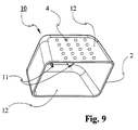
- FIG. 2 shows a push-on cap according to a further embodiment of the Invention bearing the general reference number 10.
- the knob-like structures 4 in the peripheral wall 2 of the push-on cap 10 are provided on diametrically opposite broad sides 12. she thereby give the user an indication of where a finger force is applied should be to deform the broadsides 12. Such a deformation of the Broad sides 12 is z. B. required to snap assembly 11 of the push-on cap 10 out of engagement with complementary rear gripping means on a container (not to bring the cap 10 off the container if desired to remove in order to be able to output its content.
- the peripheral wall of a screw cap to be formed Improve handling.
- the knob-like structures could also be on an outer cap, which comprises an inner closure cap, can be provided, to make it easier to remove the outer cap.
- the wall a mountable on a container or a cap, e.g. B. clip-on board, plaque, plate or the like (not shown) in the aforementioned Formed and provided with knob-like structures.
- additional equipment also includes a peripheral wall Container or a cap covering bandage (also not shown) a.
Landscapes
- Engineering & Computer Science (AREA)
- Mechanical Engineering (AREA)
- Ceramic Engineering (AREA)
- Closures For Containers (AREA)
- Laminated Bodies (AREA)
- Containers Having Bodies Formed In One Piece (AREA)
- Details Of Rigid Or Semi-Rigid Containers (AREA)
- Packaging Of Annular Or Rod-Shaped Articles, Wearing Apparel, Cassettes, Or The Like (AREA)
- Buffer Packaging (AREA)
- Tires In General (AREA)
- Supplying Of Containers To The Packaging Station (AREA)
- Processing And Handling Of Plastics And Other Materials For Molding In General (AREA)
Description
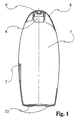
- Figur 1
- einen Längsschnitt durch eine Flasche nach einem ersten erfindungsgemäßen Ausführungsbeispiel, geschnitten entlang der Linie I-I in Figur 6,
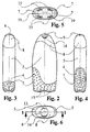
- Figur 2
- eine Ansicht der Flasche nach Figur 1 von vorn,
- Figur 3
- eine Ansicht der Flasche nach den Figuren 1 und 2 von der einen Seite,
- Figur 4
- eine Seitenansicht der Flasche nach den Figuren 1 bis 3 von der anderen Seite,
- Figur 5
- eine Ansicht der Flasche nach den Figuren 1 bis 4 von unten,
- Figur 6
- eine Ansicht der Flasche nach den Figuren 1 bis 5 von oben,
- Figur 7
- eine perspektivische Ansicht der Flasche nach den Figuren 1 bis 6 in Explosionsdarstellung,
- Figur 8
- eine Teilansicht eines erfindungsgemäßen Behälters von vorne nach einer zweiten Ausführungsform der Erfindung und
- Figur 9
- in perspektivischer Ansicht eine Aufsteckkappe nach einer dritten erfindungsgemäßen Ausführungsform.
- 1
- Behälter
- 2
- Umfangswand
- 3
- Bodenwand
- 4
- noppenartige Struktur
- 5
- Flaschenkörper
- 6
- Öffnung
- 7
- separates Kunststoffteil
- 8
- Verschluss
- 9
- Verschlussdeckel
- 10
- Aufsteckkappe
- 11
- Rastmontagemittel
- 12
- Breitseite
- 13
- Filmscharnier
- 14
- Griffmulde
- 15
- Bereich
- 16
- Schienen
- 17
- Hinterschneidung
- 18
- Rastelement
- 19
- Öffnung
Claims (13)
- Kunststoffflasche (1), die einen blasgeformten Flaschenkörper (5) und mindestens einen lokal begrenzten Bereich ihrer äußeren Oberfläche mit einem gegenüber dem Kunststoffmaterial des Flaschenkörpers (5) weicheren Kunststoffmaterial aufweist,
dadurch gekennzeichnet, dass der lokal begrenzte Bereich von einem zum Flaschenkörper (5) separaten, an diesem angebrachten, spritzgegossenen Kunststoffteil (7) aus einem thermoplastischen Elastomer mit gummiartiger Haptik gebildet ist. - Kunststoffflasche nach Anspruch 1,
dadurch gekennzeichnet, dass das Kunststoffteil (7) auf gegenüberliegendenen Seitenbereichen der Kunststoffflasche (1) eine unterschiedliche Längserstreckung aufweist. - Kunststoffflasche nach Anspruch 1 oder 2,
dadurch gekennzeichnet, dass das Kunststoffteil (7) nur im unteren oder nur im oberen Teil der Kunststoffflasche (1) vorgesehen ist. - Kunststoffflasche nach einem der vorangehenden Ansprüche,
dadurch gekennzeichnet, dass das Kunststoffteil (7) auf die Unterseite des Flaschenkörpers (5) aufgesetzt ist. - Kunststoffflasche nach einem der vorangehenden Ansprüche,
dadurch gekennzeichnet, dass das separate Kunststoffteil (7) ein im Zweikomponentenspritzgußverfahren hergestelltes Zweikomponenten-Kunststoffformteil ist. - Kunststoffflasche nach Anspruch 5,
dadurch gekennzeichnet, dass das Kunststoffteil (7) mehrschalig mit einer inneren Kernschicht aus einem Kunststoffmaterial mit einer größeren Härte und einer demgegenüber weicheren Außenschicht aus dem thermoplastischen Elastomer mit gummiartiger Haptik ausgebildet ist. - Kunststoffflasche nach einem der Ansprüche 5 bis 6,
dadurch gekennzeichnet, dass sich, insbesondere im Bodenbereich des Flaschenkörpers (5), die Innenschicht bereichsweise (15) durch die Außenschicht hindurch erstreckt. - Kunststoffflasche nach einem der vorangehenden Ansprüche,
dadurch gekennzeichnet, dass innerhalb des Kunststoffteils (7) in Längsrichtung verlaufende Kunststoffschienen (16) in entsprechende Hinterschneidungen des Flaschenkörpers (5) eingreifen. - Kunststoffflasche nach Anspruch 8,
dadurch gekennzeichnet, dass das Kunststoffteil (7) mit Rastelementen (18) des Flaschenkörpers (5) in Eingriff stehende, an den Kunststoffschienen (16) ausgebildete Rastelemente aufweist. - Kunststoffflasche nach einem der vorangehenden Ansprüche,
dadurch gekennzeichnet, dass das jeweils härtere Kunststoffmaterial ein Polyolefin, insbesondere Polyethylen (PE) oder Polypropylen (PP), ist. - Kunststoffflasche nach einem der vorangehenden Ansprüche,
dadurch gekennzeichnet, dass die äußere Oberfläche des Kunststoffteils (7) mit dem übrigen Teil der äußeren Oberfläche der Kunststoffflasche (1) im wesentlichen fluchtet. - Kunststoffflasche nach einem der vorangehenden Ansprüche,
dadurch gekennzeichnet, dass das Kunststoffteil (7) eine noppenartige Struktur (4) an der äußeren Oberfläche aufweist. - Kunststoffflasche nach Anspruch 12,
dadurch gekennzeichnet, dass die noppenartige Struktur (4) über die äußere Oberfläche des Flaschenkörpers (5) um ein geringes Maß vorsteht.
Priority Applications (1)
| Application Number | Priority Date | Filing Date | Title |
|---|---|---|---|
| SI200030388T SI1240083T1 (en) | 1999-11-30 | 2000-10-21 | Bottle made of plastic |
Applications Claiming Priority (7)
| Application Number | Priority Date | Filing Date | Title |
|---|---|---|---|
| DE29921066 | 1999-11-30 | ||
| DE29921066U | 1999-11-30 | ||
| DE29921877U DE29921877U1 (de) | 1999-11-30 | 1999-12-13 | Verpackungsmittel |
| DE29921877U | 1999-12-13 | ||
| DE10027673A DE10027673A1 (de) | 1999-11-30 | 2000-06-03 | Verpackungsmittel |
| DE10027673 | 2000-06-03 | ||
| PCT/EP2000/010392 WO2001040066A1 (de) | 1999-11-30 | 2000-10-21 | Verpackungsmittel |
Publications (2)
| Publication Number | Publication Date |
|---|---|
| EP1240083A1 EP1240083A1 (de) | 2002-09-18 |
| EP1240083B1 true EP1240083B1 (de) | 2004-03-03 |
Family
ID=27213899
Family Applications (1)
| Application Number | Title | Priority Date | Filing Date |
|---|---|---|---|
| EP00974436A Expired - Lifetime EP1240083B1 (de) | 1999-11-30 | 2000-10-21 | Kunststoffflasche |
Country Status (13)
| Country | Link |
|---|---|
| EP (1) | EP1240083B1 (de) |
| CN (1) | CN1184108C (de) |
| AT (1) | ATE260820T1 (de) |
| CZ (1) | CZ294214B6 (de) |
| DE (1) | DE20023662U1 (de) |
| DK (1) | DK1240083T3 (de) |
| EG (1) | EG22384A (de) |
| ES (1) | ES2216982T3 (de) |
| HU (1) | HUP0203512A3 (de) |
| PL (1) | PL357271A1 (de) |
| PT (1) | PT1240083E (de) |
| SK (1) | SK9472002A3 (de) |
| WO (1) | WO2001040066A1 (de) |
Families Citing this family (2)
| Publication number | Priority date | Publication date | Assignee | Title |
|---|---|---|---|---|
| WO2007098837A1 (de) * | 2006-02-27 | 2007-09-07 | Alpla-Werke Alwin Lehner Gmbh & Co. Kg | Herstellverfahren für extrusionsgeblasene kunststoffflaschen und extrusionsgeblasene kunststoffflasche |
| FR2973009B1 (fr) * | 2011-03-24 | 2014-02-21 | Oreal | Dispositif et ensemble pour le conditionnement d'un produit a melanger extemporanement avec un autre produit |
Citations (1)
| Publication number | Priority date | Publication date | Assignee | Title |
|---|---|---|---|---|
| DE19610194A1 (de) * | 1996-03-15 | 1997-09-18 | Wella Ag | Behälter aus Kunststoff und Verfahren zur Herstellung eines Behälters |
Family Cites Families (5)
| Publication number | Priority date | Publication date | Assignee | Title |
|---|---|---|---|---|
| DE1940455A1 (de) * | 1969-08-08 | 1971-02-18 | Genossenschaft Deutscher Brunn | Getraenkeflasche |
| DE9311499U1 (de) * | 1993-08-02 | 1993-11-25 | Heinz Plastics GmbH, 96355 Tettau | Rundflasche |
| EP0861038A4 (de) * | 1995-09-07 | 2004-09-22 | Nini Policappelli | Behälter und deckel |
| DE19721463A1 (de) * | 1997-05-22 | 1998-11-26 | Karlheinz Wiedemann | Gefäß mit einer Haltevorrichtung sowie ein Verfahren zu dessen Herstellung |
| BR9705400A (pt) * | 1997-11-03 | 1999-12-07 | Cosmeticos Natural Ind Com | Sistema de acondicionamento e brinquedo oscilante |
-
2000
- 2000-06-03 DE DE20023662U patent/DE20023662U1/de not_active Expired - Lifetime
- 2000-10-21 EP EP00974436A patent/EP1240083B1/de not_active Expired - Lifetime
- 2000-10-21 CN CNB008164460A patent/CN1184108C/zh not_active Expired - Fee Related
- 2000-10-21 DK DK00974436T patent/DK1240083T3/da active
- 2000-10-21 PL PL00357271A patent/PL357271A1/xx not_active IP Right Cessation
- 2000-10-21 ES ES00974436T patent/ES2216982T3/es not_active Expired - Lifetime
- 2000-10-21 PT PT00974436T patent/PT1240083E/pt unknown
- 2000-10-21 SK SK947-2002A patent/SK9472002A3/sk unknown
- 2000-10-21 HU HU0203512A patent/HUP0203512A3/hu unknown
- 2000-10-21 AT AT00974436T patent/ATE260820T1/de not_active IP Right Cessation
- 2000-10-21 WO PCT/EP2000/010392 patent/WO2001040066A1/de not_active Ceased
- 2000-10-21 CZ CZ20021879A patent/CZ294214B6/cs not_active IP Right Cessation
- 2000-11-01 EG EG20001382A patent/EG22384A/xx active
Patent Citations (1)
| Publication number | Priority date | Publication date | Assignee | Title |
|---|---|---|---|---|
| DE19610194A1 (de) * | 1996-03-15 | 1997-09-18 | Wella Ag | Behälter aus Kunststoff und Verfahren zur Herstellung eines Behälters |
Also Published As
| Publication number | Publication date |
|---|---|
| DE20023662U1 (de) | 2005-05-12 |
| EG22384A (en) | 2003-01-29 |
| CZ20021879A3 (cs) | 2004-03-17 |
| PT1240083E (pt) | 2004-07-30 |
| WO2001040066A1 (de) | 2001-06-07 |
| HK1050666A1 (en) | 2003-07-04 |
| CZ294214B6 (cs) | 2004-10-13 |
| SK9472002A3 (en) | 2002-12-03 |
| HUP0203512A3 (en) | 2005-01-28 |
| HUP0203512A2 (hu) | 2003-03-28 |
| EP1240083A1 (de) | 2002-09-18 |
| ES2216982T3 (es) | 2004-11-01 |
| CN1402683A (zh) | 2003-03-12 |
| DK1240083T3 (da) | 2004-07-05 |
| ATE260820T1 (de) | 2004-03-15 |
| CN1184108C (zh) | 2005-01-12 |
| PL357271A1 (en) | 2004-07-26 |
Similar Documents
| Publication | Publication Date | Title |
|---|---|---|
| DE69904421T2 (de) | Kippbetätigte Ausgabevorrichtung | |
| DE69716373T2 (de) | Behälter mit einem Farbband | |
| DE69624069T2 (de) | Flasche mit einem Henkel und Verfahren zur Herstellung der Flasche durch Streckblasformen | |
| DE60301752T2 (de) | Verfahren zur Überwachung einer Zugriffsablaufsteuerung für ein Kommunikationsmedium einer Kommunikationssteuerung eines Kommunikationssystems | |
| EP0419790B1 (de) | Verschluss aus Kunststoff für Behälter- und Flaschenmündungen | |
| DE69905246T2 (de) | Vorrichtung zum aufbewahren von kontaktlinsen und lösung für kontaktlinsen | |
| DE60301812T9 (de) | Einheit zur Aufbewahrung eines Produktes, insbesondere von Kosmetika | |
| EP0167783A1 (de) | Verschliessvorrichtung für die Entnahmeöffnung eines Behälters und zugehöriger Behälter | |
| EP0524279B1 (de) | Kunststoffverschluss mit garantieelement | |
| CH397457A (de) | Verschluss an einer Flasche | |
| DE2942068A1 (de) | Schraubdeckel mit verschlussumrandung | |
| DE102019007143A1 (de) | Verschluss für einen Behälter, Behälter, Spritzgusswerkzeugsatz und Verfahren | |
| DE102007018358B4 (de) | Relief-Overmolding | |
| DE2226217A1 (de) | Spundfass aus kunststoff mit einer oder mehreren spundoeffnungen | |
| EP1421008B1 (de) | Becher zum stülpen über oder unter eine getränkeflasche, getränkeflasche zur aufnahme eines stülpbaren bechers und kombination derselben | |
| DE10027673A1 (de) | Verpackungsmittel | |
| DE69902567T2 (de) | Öffnungsvorrichtung | |
| DE3519296A1 (de) | Verschliessvorrichtung fuer die entnahmeoeffnung eines behaelters und zugehoeriger behaelter | |
| DE19809732A1 (de) | Verschluß | |
| DE10201840B4 (de) | Verpackungseinheit | |
| DE10239319B4 (de) | Zweikomponenten Kunstoffbehälter | |
| CH696070A5 (de) | Schwenkdeckelbehälter aus Kunststoff. | |
| EP1240083A1 (de) | Verpackungsmittel | |
| DE2801277A1 (de) | Verschlussvorrichtung fuer flaschen, kruege und dergleichen behaelter | |
| WO2018086914A1 (de) | Verschlussvorrichtung und behälter mit einer solchen verschlussvorrichtung |
Legal Events
| Date | Code | Title | Description |
|---|---|---|---|
| PUAI | Public reference made under article 153(3) epc to a published international application that has entered the european phase |
Free format text: ORIGINAL CODE: 0009012 |
|
| 17P | Request for examination filed |
Effective date: 20020518 |
|
| AK | Designated contracting states |
Kind code of ref document: A1 Designated state(s): AT BE CH CY DE DK ES FI FR GB GR IE IT LI LU MC NL PT SE |
|
| AX | Request for extension of the european patent |
Free format text: AL;LT;LV;MK;RO PAYMENT 20020518;SI PAYMENT 20020518 |
|
| 17Q | First examination report despatched |
Effective date: 20021106 |
|
| RTI1 | Title (correction) |
Free format text: BOTTLE MADE OF PLASTIC |
|
| GRAP | Despatch of communication of intention to grant a patent |
Free format text: ORIGINAL CODE: EPIDOSNIGR1 |
|
| GRAS | Grant fee paid |
Free format text: ORIGINAL CODE: EPIDOSNIGR3 |
|
| GRAA | (expected) grant |
Free format text: ORIGINAL CODE: 0009210 |
|
| AK | Designated contracting states |
Kind code of ref document: B1 Designated state(s): AT BE CH CY DE DK ES FI FR GB GR IE IT LI LU MC NL PT SE |
|
| AX | Request for extension of the european patent |
Extension state: RO SI |
|
| PG25 | Lapsed in a contracting state [announced via postgrant information from national office to epo] |
Ref country code: CY Free format text: LAPSE BECAUSE OF FAILURE TO SUBMIT A TRANSLATION OF THE DESCRIPTION OR TO PAY THE FEE WITHIN THE PRESCRIBED TIME-LIMIT Effective date: 20040303 |
|
| REG | Reference to a national code |
Ref country code: GB Ref legal event code: FG4D Free format text: NOT ENGLISH |
|
| REG | Reference to a national code |
Ref country code: CH Ref legal event code: EP |
|
| REG | Reference to a national code |
Ref country code: IE Ref legal event code: FG4D Free format text: GERMAN |
|
| REF | Corresponds to: |
Ref document number: 50005559 Country of ref document: DE Date of ref document: 20040408 Kind code of ref document: P |
|
| REG | Reference to a national code |
Ref country code: SE Ref legal event code: TRGR |
|
| REG | Reference to a national code |
Ref country code: GR Ref legal event code: EP Ref document number: 20040401692 Country of ref document: GR |
|
| GBT | Gb: translation of ep patent filed (gb section 77(6)(a)/1977) |
Effective date: 20040525 |
|
| REG | Reference to a national code |
Ref country code: DK Ref legal event code: T3 |
|
| REG | Reference to a national code |
Ref country code: PT Ref legal event code: SC4A Free format text: AVAILABILITY OF NATIONAL TRANSLATION Effective date: 20040517 |
|
| LTIE | Lt: invalidation of european patent or patent extension |
Effective date: 20040303 |
|
| PG25 | Lapsed in a contracting state [announced via postgrant information from national office to epo] |
Ref country code: LU Free format text: LAPSE BECAUSE OF NON-PAYMENT OF DUE FEES Effective date: 20041021 |
|
| PG25 | Lapsed in a contracting state [announced via postgrant information from national office to epo] |
Ref country code: MC Free format text: LAPSE BECAUSE OF NON-PAYMENT OF DUE FEES Effective date: 20041031 |
|
| REG | Reference to a national code |
Ref country code: ES Ref legal event code: FG2A Ref document number: 2216982 Country of ref document: ES Kind code of ref document: T3 |
|
| ET | Fr: translation filed | ||
| PLBE | No opposition filed within time limit |
Free format text: ORIGINAL CODE: 0009261 |
|
| STAA | Information on the status of an ep patent application or granted ep patent |
Free format text: STATUS: NO OPPOSITION FILED WITHIN TIME LIMIT |
|
| REG | Reference to a national code |
Ref country code: SI Ref legal event code: IF |
|
| 26N | No opposition filed |
Effective date: 20041206 |
|
| PGFP | Annual fee paid to national office [announced via postgrant information from national office to epo] |
Ref country code: PT Payment date: 20080925 Year of fee payment: 9 |
|
| PGFP | Annual fee paid to national office [announced via postgrant information from national office to epo] |
Ref country code: NL Payment date: 20081005 Year of fee payment: 9 |
|
| PGFP | Annual fee paid to national office [announced via postgrant information from national office to epo] |
Ref country code: CH Payment date: 20081031 Year of fee payment: 9 Ref country code: DK Payment date: 20081013 Year of fee payment: 9 Ref country code: IE Payment date: 20081015 Year of fee payment: 9 |
|
| PGFP | Annual fee paid to national office [announced via postgrant information from national office to epo] |
Ref country code: AT Payment date: 20081013 Year of fee payment: 9 Ref country code: FI Payment date: 20081014 Year of fee payment: 9 |
|
| PGFP | Annual fee paid to national office [announced via postgrant information from national office to epo] |
Ref country code: IT Payment date: 20081029 Year of fee payment: 9 Ref country code: BE Payment date: 20081010 Year of fee payment: 9 Ref country code: SE Payment date: 20081022 Year of fee payment: 9 |
|
| PGFP | Annual fee paid to national office [announced via postgrant information from national office to epo] |
Ref country code: GB Payment date: 20081015 Year of fee payment: 9 Ref country code: GR Payment date: 20080919 Year of fee payment: 9 |
|
| BERE | Be: lapsed |
Owner name: *HENKEL K.G.A.A. Effective date: 20091031 |
|
| REG | Reference to a national code |
Ref country code: PT Ref legal event code: MM4A Free format text: LAPSE DUE TO NON-PAYMENT OF FEES Effective date: 20100421 |
|
| REG | Reference to a national code |
Ref country code: NL Ref legal event code: V1 Effective date: 20100501 |
|
| REG | Reference to a national code |
Ref country code: CH Ref legal event code: PL |
|
| EUG | Se: european patent has lapsed | ||
| REG | Reference to a national code |
Ref country code: DK Ref legal event code: EBP |
|
| REG | Reference to a national code |
Ref country code: IE Ref legal event code: MM4A |
|
| PG25 | Lapsed in a contracting state [announced via postgrant information from national office to epo] |
Ref country code: PT Free format text: LAPSE BECAUSE OF NON-PAYMENT OF DUE FEES Effective date: 20100421 Ref country code: NL Free format text: LAPSE BECAUSE OF NON-PAYMENT OF DUE FEES Effective date: 20100501 |
|
| REG | Reference to a national code |
Ref country code: SI Ref legal event code: KO00 Effective date: 20100615 |
|
| PG25 | Lapsed in a contracting state [announced via postgrant information from national office to epo] |
Ref country code: FI Free format text: LAPSE BECAUSE OF NON-PAYMENT OF DUE FEES Effective date: 20091021 Ref country code: AT Free format text: LAPSE BECAUSE OF NON-PAYMENT OF DUE FEES Effective date: 20091021 |
|
| PG25 | Lapsed in a contracting state [announced via postgrant information from national office to epo] |
Ref country code: BE Free format text: LAPSE BECAUSE OF NON-PAYMENT OF DUE FEES Effective date: 20091031 Ref country code: CH Free format text: LAPSE BECAUSE OF NON-PAYMENT OF DUE FEES Effective date: 20091031 Ref country code: LI Free format text: LAPSE BECAUSE OF NON-PAYMENT OF DUE FEES Effective date: 20091031 Ref country code: IE Free format text: LAPSE BECAUSE OF NON-PAYMENT OF DUE FEES Effective date: 20091021 Ref country code: GR Free format text: LAPSE BECAUSE OF NON-PAYMENT OF DUE FEES Effective date: 20100504 |
|
| PG25 | Lapsed in a contracting state [announced via postgrant information from national office to epo] |
Ref country code: GB Free format text: LAPSE BECAUSE OF NON-PAYMENT OF DUE FEES Effective date: 20091021 |
|
| PG25 | Lapsed in a contracting state [announced via postgrant information from national office to epo] |
Ref country code: DK Free format text: LAPSE BECAUSE OF NON-PAYMENT OF DUE FEES Effective date: 20091031 |
|
| PG25 | Lapsed in a contracting state [announced via postgrant information from national office to epo] |
Ref country code: IT Free format text: LAPSE BECAUSE OF NON-PAYMENT OF DUE FEES Effective date: 20091021 |
|
| PG25 | Lapsed in a contracting state [announced via postgrant information from national office to epo] |
Ref country code: SE Free format text: LAPSE BECAUSE OF NON-PAYMENT OF DUE FEES Effective date: 20091022 |
|
| PGFP | Annual fee paid to national office [announced via postgrant information from national office to epo] |
Ref country code: ES Payment date: 20140911 Year of fee payment: 15 |
|
| PGFP | Annual fee paid to national office [announced via postgrant information from national office to epo] |
Ref country code: DE Payment date: 20141014 Year of fee payment: 15 Ref country code: FR Payment date: 20141008 Year of fee payment: 15 |
|
| REG | Reference to a national code |
Ref country code: DE Ref legal event code: R119 Ref document number: 50005559 Country of ref document: DE |
|
| PG25 | Lapsed in a contracting state [announced via postgrant information from national office to epo] |
Ref country code: DE Free format text: LAPSE BECAUSE OF NON-PAYMENT OF DUE FEES Effective date: 20160503 |
|
| REG | Reference to a national code |
Ref country code: FR Ref legal event code: ST Effective date: 20160630 |
|
| PG25 | Lapsed in a contracting state [announced via postgrant information from national office to epo] |
Ref country code: FR Free format text: LAPSE BECAUSE OF NON-PAYMENT OF DUE FEES Effective date: 20151102 |
|
| REG | Reference to a national code |
Ref country code: ES Ref legal event code: FD2A Effective date: 20161128 |
|
| PG25 | Lapsed in a contracting state [announced via postgrant information from national office to epo] |
Ref country code: ES Free format text: LAPSE BECAUSE OF NON-PAYMENT OF DUE FEES Effective date: 20151022 |