EP1237784B1 - Appareil et procede de traitement de monnaie - Google Patents
Appareil et procede de traitement de monnaie Download PDFInfo
- Publication number
- EP1237784B1 EP1237784B1 EP00980193A EP00980193A EP1237784B1 EP 1237784 B1 EP1237784 B1 EP 1237784B1 EP 00980193 A EP00980193 A EP 00980193A EP 00980193 A EP00980193 A EP 00980193A EP 1237784 B1 EP1237784 B1 EP 1237784B1
- Authority
- EP
- European Patent Office
- Prior art keywords
- coin
- coins
- bag
- sealer
- processing apparatus
- Prior art date
- Legal status (The legal status is an assumption and is not a legal conclusion. Google has not performed a legal analysis and makes no representation as to the accuracy of the status listed.)
- Expired - Lifetime
Links
- 238000012545 processing Methods 0.000 title claims description 33
- 238000000034 method Methods 0.000 title claims description 6
- 238000004806 packaging method and process Methods 0.000 claims description 53
- 229920003023 plastic Polymers 0.000 claims description 53
- 239000004033 plastic Substances 0.000 claims description 52
- 230000007246 mechanism Effects 0.000 claims description 27
- 239000005022 packaging material Substances 0.000 claims description 13
- 238000003672 processing method Methods 0.000 claims description 4
- 239000000463 material Substances 0.000 claims description 2
- 239000011888 foil Substances 0.000 description 44
- 238000003860 storage Methods 0.000 description 17
- 238000007789 sealing Methods 0.000 description 14
- 230000006870 function Effects 0.000 description 6
- 238000003466 welding Methods 0.000 description 5
- 230000005540 biological transmission Effects 0.000 description 4
- 230000008569 process Effects 0.000 description 3
- 238000013461 design Methods 0.000 description 2
- 230000015654 memory Effects 0.000 description 2
- 230000003287 optical effect Effects 0.000 description 2
- 238000003825 pressing Methods 0.000 description 2
- 238000005096 rolling process Methods 0.000 description 2
- 229920001342 Bakelite® Polymers 0.000 description 1
- VGGSQFUCUMXWEO-UHFFFAOYSA-N Ethene Chemical compound C=C VGGSQFUCUMXWEO-UHFFFAOYSA-N 0.000 description 1
- XUIMIQQOPSSXEZ-UHFFFAOYSA-N Silicon Chemical compound [Si] XUIMIQQOPSSXEZ-UHFFFAOYSA-N 0.000 description 1
- 230000001464 adherent effect Effects 0.000 description 1
- XAGFODPZIPBFFR-UHFFFAOYSA-N aluminium Chemical compound [Al] XAGFODPZIPBFFR-UHFFFAOYSA-N 0.000 description 1
- 229910052782 aluminium Inorganic materials 0.000 description 1
- 239000004411 aluminium Substances 0.000 description 1
- 239000004637 bakelite Substances 0.000 description 1
- 238000004891 communication Methods 0.000 description 1
- 238000010276 construction Methods 0.000 description 1
- 238000011161 development Methods 0.000 description 1
- 230000018109 developmental process Effects 0.000 description 1
- 230000000694 effects Effects 0.000 description 1
- 229920001971 elastomer Polymers 0.000 description 1
- 238000010438 heat treatment Methods 0.000 description 1
- 230000001939 inductive effect Effects 0.000 description 1
- 230000003993 interaction Effects 0.000 description 1
- 229910000953 kanthal Inorganic materials 0.000 description 1
- 229920001684 low density polyethylene Polymers 0.000 description 1
- 239000004702 low-density polyethylene Substances 0.000 description 1
- 238000012423 maintenance Methods 0.000 description 1
- 239000000203 mixture Substances 0.000 description 1
- 229920001296 polysiloxane Polymers 0.000 description 1
- 230000001105 regulatory effect Effects 0.000 description 1
- 238000007493 shaping process Methods 0.000 description 1
- 229910052710 silicon Inorganic materials 0.000 description 1
- 239000010703 silicon Substances 0.000 description 1
Images


Classifications
-
- G—PHYSICS
- G07—CHECKING-DEVICES
- G07D—HANDLING OF COINS OR VALUABLE PAPERS, e.g. TESTING, SORTING BY DENOMINATIONS, COUNTING, DISPENSING, CHANGING OR DEPOSITING
- G07D9/00—Counting coins; Handling of coins not provided for in the other groups of this subclass
- G07D9/06—Devices for stacking or otherwise arranging coins on a support, e.g. apertured plate for use in counting coins
- G07D9/065—Devices for wrapping coins
-
- B—PERFORMING OPERATIONS; TRANSPORTING
- B65—CONVEYING; PACKING; STORING; HANDLING THIN OR FILAMENTARY MATERIAL
- B65B—MACHINES, APPARATUS OR DEVICES FOR, OR METHODS OF, PACKAGING ARTICLES OR MATERIALS; UNPACKING
- B65B9/00—Enclosing successive articles, or quantities of material, e.g. liquids or semiliquids, in flat, folded, or tubular webs of flexible sheet material; Subdividing filled flexible tubes to form packages
- B65B9/02—Enclosing successive articles, or quantities of material between opposed webs
-
- G—PHYSICS
- G07—CHECKING-DEVICES
- G07D—HANDLING OF COINS OR VALUABLE PAPERS, e.g. TESTING, SORTING BY DENOMINATIONS, COUNTING, DISPENSING, CHANGING OR DEPOSITING
- G07D3/00—Sorting a mixed bulk of coins into denominations
- G07D3/14—Apparatus driven under control of coin-sensing elements
Definitions
- the present invention relates to a coin processing apparatus, comprising an opening for receiving a plurality of coins of different types, a coin sensor adapted to determine a respective type of individual coins among the plurality of coins, a controller operatively coupled to the coin sensor, and a coin separator operatively coupled to the controller and capable of separating the individual coins from the plurality of coins under control from the controller. More specifically, the invention is directed at a coin packaging device in such a coin processing apparatus. The invention also relates to a coin processing method.
- Coin packaging devices for performing quick and reliable packaging of coins are previously known.
- the packaging devices commonly perform packaging of the coins in bags in which a predetermined number of coins are filled.
- the devices that today exist on the market for packaging coins in paper or plastic bags are big and bulky.
- GB-A-1 364 564 discloses an apparatus for forming bags of heat sealable packaging material, which then are filled with coins.
- the heat sealable packaging material is supplied as at least one web.
- the apparatus comprises means for forming a loop of the web or webs and a guide housing adapted to enclose the web or webs, fed thereto for shaping the web or webs into a tube.
- the apparatus further comprises swingers mounted on either sides of the web or webs of packaging material and formed in the guide housing, and supporting heat sealing jaws for transverse sealing of portions of the web or webs projecting from the guide housing at the lower end thereof.
- WO 99/33030 discloses a coin counting and sorting device with active coin handling means. While coins in paper tubes are easy to handle and transport, paper tubes are less desirable for other reasons. For instance, paper as a packaging material is relatively expensive. Moreover, the fact that the coins are stacked in piles requires a complicated mechanical coin packaging device, which additionally generally suffers from a low operating speed. The apparatus in GB-A-1 364 564 complicates the storage of coin bags because when each coin bag is finally sealed, it is cut from the other bags and is delivered into another device. GB-A-1 364 564 does not contain any details of how such a coin packaging device may be incorporated in for example a self-service coin counting and/or sorting machine.
- WO 00/37317 discloses a coin handling machine that manufactures containers for coins in the form of tubes. Coins are supplied into a plastic tube, which is then sealed at two positions. The part of the tube that contains the coins is then separated from the rest of the tube.
- the invention aims at providing a coin processing apparatus that facilitates the subsequent handling of the bags filled with coins for human users.
- a coin processing apparatus having an opening for receiving a plurality of coins of different types.
- the apparatus further has a coin sensor adapted to determine a respective type of individual coins among the plurality of coins, a controller operatively coupled to the coin sensor, and a coin separator operatively coupled to the controller and capable of separating the individual coins from the plurality of coins under control from the controller.
- the apparatus comprises a coin packaging device having: a coin inlet, a supply of packaging material, and a packaging mechanism capable of producing a plurality of coin bags from the supply.
- the coin inlet is coupled to the coin separator so as to receive the individual coins therefrom, the packaging mechanism is adapted to enclose the individual coins in any of the coin bags, and the controller is adapted to control the packaging mechanism according to a specified packaging scheme, so that at least two different coin types are packaged in the coin bags in a continuous operation.
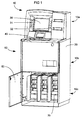
- FIG 1 shows a coin processing apparatus 10 according to the present invention comprising a housing 20 and an user interface area 30 at its upper portion 10a, where a coin inlet 40 is placed.
- the apparatus also has a middle portion 10b in which a coin separator 50 (not shown in FIG 1) is placed.
- the apparatus 10 further comprises at least one cover 60, here shown in an open position, for covering the interior of a lower portion 10c of the apparatus 10.
- the lower part 10c of the apparatus may contain different components with different functions, e g coin boxes only used for storing processed coins or, preferably, coin packaging devices 70.
- the coin processing apparatus 10 and more specific the coin separator 50 may be any kind of coin handling apparatus, e g a coin counting and/or sorting machine using active or passive coin handling means.
- the coin processing apparatus 10 may also be a coin handling machine for self-service in which coins may be deposited and/or collected by an user.
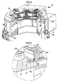
- FIG 2 two main components of the coin processing apparatus 10 are shown in a preferred embodiment.
- the top component is a perspective view of the coin separator 50 and the lower component is the coin packaging device 70, which is shown in a perspective view in section for clarity reasons, for packaging coins that are generally represented by the reference numeral 15 in batches 80.
- FIGs 3-5 illustrate a preferred embodiment of the coin separator 50.
- One suitable separator in the form of a coin counter/sorter is described in e.g. WO99/33030, which is fully incorporated herein by reference.
- the coin separator handles a plurality of coins 15. Coins at specific positions in the coin separator are labelled 15a, 15b, etc., as will be described below.
- the coin separator 50 comprises an apparatus frame 9, a plurality of coin chutes 18, 19 and corresponding coin receptacle attachments 70', which are all circularly arranged around the central components of the separator.
- the attachments 70' may support respective coin receptacles (not shown), which are adapted to receive and store coins that have been processed by the separator, and which are of a different kind than plastic coin bags.
- a first rotating disk 1 of the coin separator 50 is arranged to receive an unsorted plurality of coins 15 from e.g. a human user through the coin inlet 40.
- an unsorted plurality of coins 15 from e.g. a human user through the coin inlet 40.
- the disk 1 is rotated in a direction indicated by an arrow 22 in FIG 3, the coins deposited onto the disk are accelerated by the centrifugal force in the radial direction of the disk towards a stationary ring 2, as indicated by 15a in FIG 3.
- the plurality of coins are driven through an opening 23 in the stationary ring 2 and are forced into contact with the inside of a resilient rim 14 on a rotating ring 3 (see 15b).
- FIG 5 provides a detailed illustration of a coin 15g, which is engaged at a short portion 15g' thereof between the rim 14 and the disk 1. As appears from FIG 3, the coin 15g has been carried approximately 180° around its circular path starting from the point of engagement at 15c. Coins of small diameter (as seen at 15c and 15e) as well as coins of a larger diameter (as seen at 15d and 15g) may be freely engaged and transported between the rim and the disk in the manner described above.
- a coin sensor 8 is arranged to detect the passage of a respective coin 15d and to identify the denomination or type thereof.
- the coin sensor 8 may operate in a contactless manner known per se in the technical field, such as by inductive or optical means, as is readily realized by a man skilled in the art.
- the coin separator 50 is provided with an encoder 24 for determining the rotational speed of the rotating disk 1 and the rotating ring 3.
- the encoder 24 as well as the coin sensor 8 are operatively connected to a controller 11 (shown in FIG 3).
- the controller 11 is arranged to use information received from the encoder and the coin sensor 8 to determine the position of each coin 15d, 15e, 15g relative to the coin sensor 8 at different points in time.
- the controller 11 will activate a deflector unit 16, 17 located at each off-sort station.
- each coin chute comprises an upper portion 18 and a lower portion 19.
- the upper portion 18 has a downward slope, while the lower portion 19 runs essentially vertically.
- the coin separator 50 shown in FIGs 3-5 is incorporated in the coin processing apparatus 10 shown in FIG 1.
- the coin processing apparatus may advantageously be used as a coin deposit machine on a self-service basis by an untrained user (e.g. a shop visitor, a bank customer, etc.), who may deposit a plurality of coins of mixed denominations and/or currencies, for instance originating from his pocket, wallet or savings-box.
- the coins are put by the user into the coin inlet or intake 40 in the apparatus 10, and then the user initiates the coin processing by pressing a start button or the like.
- the coin processing apparatus is arranged to count and/or sort the coins deposited by the user and provide a receipt or voucher in return.
- the receipt or voucher may be used as payment for articles offered in a shop.
- a bank account belonging to the user may be credited an amount corresponding to the total value of the coins.
- the counting and/or sorting process is initiated.
- the process may be initiated by pressing any of a number of keys 31 or 32, shown in FIG 1, or, alternatively, the process may be automatically initiated by a detector in the coin inlet 40.
- the coins are supplied to the upper surface of the coin separator 50, as described above.
- the coins are then sequentially transported by the ring 3 and the disk 1 around a circular sorting path.
- the coins are deflected at any of the off-sort stations 6 and fall one by one into respective coin chutes 18, 19. ,
- a value representing a total amount of the coins 15 is calculated by the controller 11 of the coin separator or by separate controller means, such as a computer or CPU with associated memory.
- Coins that are rejected by the coin separator are returned in a reject tray, which is accessible to the user.
- a printer may provide a voucher or receipt.
- a total value is printed on the receipt, as described above.
- the user interface area 30 in the form of a monitor may be used for user interaction, e.g. for presenting guidance or informative messages to the user.
- the user may insert a credit card, a smart card or any other card-shaped information carrier through a card slot.
- a card reader inside the device is arranged to read information stored on the card and to act accordingly. For instance, the card may contain information regarding a bank account number to be credited, once the total amount of the coins has been determined.
- the coin-handling device 50 is advanced and may sort or count any denomination or currency of coins 15, whereby the coins may be sorted out into the coin chutes 18 and 19 in any number and order. This means that different coin batches may be sorted out containing a different number, denomination or currency in each batch. These coin batches may then be received by the coin packaging device 70. More specifically, the coin processing device 10 may receive a first coin batch with a first type and number of coins, a second batch with a second type and number of coins, and a third batch with a third type and number of coins, etc, or a mixture of coin types in each batch.
- the coin packaging device 70 may then receive a first type and number of coins and a second type and number of coins to be packaged in the same first batch, a second type and number of coins and a third type and number of coins to be packaged in a second batch, and a third type and number of coins and a fourth type and number of coins to be packaged in a third batch, etc.
- the packaging device 70 may also package more than two types of coins in each batch, as is readily understood by a man skilled in the art.
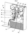
- the coin packaging device 70 is shown in a position for sealing of a batch, in the following referred to as a plastic bag 80 filled with any number or types of coins 15.
- the coin packaging device 70 comprises the coin guide 90 in communication with the coin chute 19 for receiving coins from an outlet of the coin separator 50.
- a pair of foil storage units 100 is provided in the form of magazines for a respective roll of plastic foil.
- a pair of feeders 110 are provided for feeding a predetermined length of plastic foil from the respective foil storage unit 100 to a sealing jaw 120.
- the sealing jaw comprises two sealers, a first movable sealer 120a and a second fixed sealer 120b working as an anvil for the first sealer.
- a device 130 preferably in the form of two arms, one for each storage unit, for braking and measuring the amount of plastic foil is in contact with the storage units 100.
- the braking function is required for eliminating the risk of having the plastic foils rolling out unintentionally due to the moment of inertia for each storage unit during operation.
- the sealers 120a and 120b are adapted to join the two plastic foils together so as to form the coin bag or sachet 80. As will be described in more detail later, the plastic foils are joined by resistive heating. Additionally, a drive assembly 140 is provided for moving the feeders 110. The first sealer 120a is moved by means of another drive mechanism 150. The first sealer 120a is movable from a first position 120' shown in FIGs 6 and 7 to a second position 120" shown in FIGs 8 and 9. In the first position 120' the sealing jaw 120 is closed so that a plastic bag 80 is formed by the plastic foils and may be filled with coins 15 delivered from the coin separator 50. The plastic foils are simultaneously perforated at a front part seen in the feeding direction of the bags by means of a knife 160. The knife is securely clamped between two fixed holder parts attached to the lower part of the first sealer 120a.
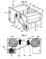
- FIGs 8 and 9 a part 71 of the coin packaging device 70 working as a bag-forming unit is shown.
- This bag-forming unit is a separate module detached from the coin packaging device.
- the sealing jaw 120 is opened for releasing the filled plastic bag 80 and ready to receive a new set of plastic foils and form a new plastic bag.
- Each filled plastic bag 80 is then fed into a final feeder mechanism 170 driven by a drive mechanism 180.
- the feeder mechanism has two functions, it feeds each plastic bag, which is attached to adjacent plastic bags forming a band 80' of plastic bags, and at the same time keeps the band of adjoined plastic bags sufficiently stretched for reducing the risk of band jams during the bag handling.
- the final feeder mechanism comprises two pair of rolls, a total of four rolls.
- the first pair o rolls is placed above the transport path for the plastic bags and the second pair of rolls is placed below the transport path.
- Each roll of the first top pair is separately suspended at one end to a frame, wherein each roll of the second pair of rolls is interconnected with each other at one end by an axle, over which the plastic bags move, and is suspended at the other end to the frame.
- the plastic bags 80 may be supplied to an external machine, an external conveyor belt or an external storage area, represented by a position A.
- the plastic bags may also be more or less permanently stored by rolling them around a pin at a position B, or lifting them to a top position C, so that a larger storage area is achieved during the bag handling.
- the plastic foil storage units 100 are shown as a separate foil supplying unit 75, which is a separate module to be attached on top of the bag-forming unit 71.
- the drive assembly 140 of the plastic foil storage units comprises a motor 141, three wheels 142, and a belt 143 for transferring the torque of the motor axle to the pair of feeders 110 of the plastic foil storage units.
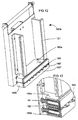
- FIG 12 shows the first sealer 120a of the sealing jaw 120 in its first position, i e when it is pressed against the second sealer 120b (not shown), whereby the plastic foils forming the plastic bag 80 (not shown) is placed between the two sealers.
- Two front surfaces 160' and 160" of the perforating knife 160 is movable by way of a spring mechanism and is shown in a depressed state because of the anvil effect from the second sealer 120b.
- An essentially U-shaped press surface of the first sealer 120a is formed by two portions 121, which form the legs of the U and extend longitudinally in the feeding direction of the plastic foils, and the two front surfaces 160' and 160". When the two sealers are pressed together, the two front surfaces will be pushed in a direction towards the first sealer and reveal the perforating knife, whereby the knife 160 perforates the plastic foils.
- each holder part 160a and 160b has movable front surfaces 160' and 160", respectively, in the form of a plate coated with silicone.
- Each front plate is attached to one end of a pin 161 protruding through a through hole in each holder part, and each pin 161 has a stop at the other end with an outer diameter larger than the inner diameter of the through hole.
- Each front plate 160' and 160" is integrated in the pin and attached perpendicularly to the pin.
- Each pin 161 is supported axially by a spring 162 enclosed in the through hole of each holder part, each spring being in contact with the interior of the associated fixed holder part at one end and in contact with the front surface 160' or 160" at the other end.
- the spring biases the adherent front surface in a direction perpendicular to the feeding direction of the plastic foils and bags 80 when the sealer jaw 120 is opened, i e when the first sealer 120a is moved away from the second sealer 120b in the first position 120' to the second position 120".
- Each pin 161 moves until it comes in contact with the holder part and stops, whereby both front surfaces 160' and 160" have passed past the edge of the knife 160 and cover it in the second open position 120" of the sealer jaw.
- FIGs 6-11 Various sensors 190 and 200 are provided in FIGs 6-11 for indicating the current positions of the feeders 110 and the first movable sealer 120a.
- Fig 14 illustrates the second sealer 120b of the sealing jaw 120.
- the second sealer has two functions: firstly it forms a fixed anvil for the first sealer when the first sealer is pressed against it in the first position 120', and secondly it joins the two plastic foils by resistive welding, thereby forming and sealing the essentially U-shaped plastic bag 80.
- the second sealer has an essentially U-shaped press surface corresponding to the first sealer, which is formed by two portions 122 creating the legs of the U and two portions 123 corresponding to the front surfaces 160' and 160" of the first sealer 120a.
- the coin packaging device 70 illustrated in FIGs 6-11 has the following operating cycle:
- FIG 8 illustrates the bag-forming unit 71 of the coin packaging device 70 in the form of a module, on which the module of the foil-supplying unit 75 in FIGs 10 and 11 is placed.
- the bag-forming unit comprises two frames 72 and 73, which function as support and attachment points for the other parts of the unit, such as motors, bearing sleeves, sensors, the final feeder mechanism 170, etc. Furthermore, the two frames are supported and held together by at least one rod 74.
- FIGs 10 and 11 illustrate the foil-supplying unit 75.
- the foil-supplying unit also has two frames 76 and 77, which function as support and attachment points for the other parts of the unit, such as motors, bearing sleeves, sensors, the feeders 110, etc. Furthermore, the two frames are supported and held together by at least one rod 78.
- a transparent plastic LDPE foil is used having a width of 100 mm, a thickness of 0.07 mm, an inner diameter of 20 mm and an outer diameter of 60 mm.
- Each roll of foil contains approximately 35.5 m of plastic foil.
- the foil rolls are placed in holders with the brake and indicator device 130 in contact with each foil roll.
- the device 130 has, as mentioned earlier, two purposes; to dispense foil and to prevent undesired or unexpected foil feeding.
- the feeders 110 have the form of a pair of rollers.
- the pair of rollers are provided with a number of resilient rings, preferably rubber rings, which interact with each other and create enough friction for feeding the predetermined length of plastic foil from a respective one of the foil storage units 100.
- a respective pair of rollers is provided for each foil storage unit 100.
- the four rolls of the final feeder mechanism 170 are provided with the same resilient rings as the feeders 100 for the same purpose.
- the rollers are driven by belt through a 24 VDC motor with a torque of 0.03 Nm and an angular frequency of 110 rpm.
- the tension of the belt is regulated by an appropriate design of the motor attachment points known to a man skilled in the art.
- the predetermined length of plastic foil is fed through the feeders 110 and is detected by means of a foil sensor.
- the foil sensor comprises a slotted optical switch and a perforated disk, which is attached to one of the driven rollers.
- the sealer jaw 120 formed by the first sealer 120a and the second sealer 120b is actuated by the drive mechanism 150 comprising a motor that drives a cam 151 via a transmission 152.
- the cam has an essentially circular shape and is eccentrically attached to an axle that is driven by the transmission.
- the drive mechanism i e the motor, the cam and the transmission, presses against a plate 124 of the first sealer 120a towards the second sealer 120b, whereby the first sealer moves by rotating around point D in FIG 9 towards the second sealer.
- the plate 124 is attached to the first sealer 120a and works as a contact surface for the cam 151.
- the plate is suspended by a spring mechanism to compensate for any tolerance differences between the cam and the plate.
- the spring mechanism of the plate also smoothens the engaging and disengaging of the cam when actuating the first sealer 120a.
- the perforator knife 160 creates holes in a section between two subsequent bags, making it easy later on for a human user to separate two adjacent plastic bags from each other by tearing them apart. Sealing and perforation occur when the plastic coin bag is filled with coins 15 through the coin guide 90.
- the heater in the second sealer 120b comprises a kanthal resistance wire stringed on bakelite blocks.
- the press surfaces 122 and 123 are designed of silicon pads, which are attached to aluminium blocks as in the first sealer 120a. Both types of blocks are attached to a frame and form the U character, as shown in more detail in FIGs 12-14.
- the perforator 160 comprises about 5-30 knives, which are attached to the holder parts 160a and 160b, as shown in FIGs 12 and 13.
- the drive mechanism 150 is illustrated in FIGs 8 and 9 and is designed to operate the sealer jaw 120 formed by the press surfaces of the sealers 120a and 120b.
- the drive mechanism provides the sealer jaw with a high welding pressure and renders the sealer jaw very compact and space efficient. Micro sensors are used for indicating the current position of the sealer jaw.
- the sealer jaw is illustrated in the closed position in FIGs 2, 6 and 7 and in the opened position in FIGs 8 and 9.
- the transmission in the form of a belt 152 of the drive mechanism transmits torque from the motor to the cam 151. Because of the fairly high torque required for the sealer jaw in order to produce enough welding pressure, and because of the frequent changes in direction, the drive mechanism is designed appropriately.
- the motor chosen is a 24 VDC motor having a torque of 0.98 Nm and an angular frequency of 17 rpm.
- the welding and bag-forming cycle for one bag 80 takes, preferably, between 7-15 seconds, more preferably between 2-10 seconds and most preferably between 1-7 seconds.
- the foil storage capacity is >300 bags but may be less or more depending on each bag size and/or the coin size.
- the packaging capacity in number of coins is, preferably, >(100-300) coins per minute and most preferably >350 coins per minute.
- the coin packaging device 70 comprises appropriate control logic circuitry 55, which are only schematically illustrated as a square unit in FIGs 6 and 7.
- the control logic circuitry is adapted to generate various control signals to the different parts of the coin packaging device, as well as to communicate with the controller 11 of the coin separator 50.
- the control logic circuitry is implemented as a CPU, micro controller, etc having appropriate memories as well as input and output means.
- the invention applies also to items, which are structurally similar to coins, such as disks, markers, tokens, etc.
- the coin packaging device 70 is constructed by modules, i e in separate units like the control logic circuitry unit 55, the bag-forming unit 71, and the foil-supplying unit 75, for simplifying the implementation of new developments and design changes.
- the module structure also facilitates the mounting and maintenance procedure of the coin packaging device 70.
Landscapes
- Physics & Mathematics (AREA)
- General Physics & Mathematics (AREA)
- Engineering & Computer Science (AREA)
- Mechanical Engineering (AREA)
- Container Filling Or Packaging Operations (AREA)
- Containers And Plastic Fillers For Packaging (AREA)
Claims (13)
- Appareil de traitement de pièces de monnaie (10), comprenant une ouverture (40) pour recevoir une pluralité de pièces de monnaie (15) de différents types ;
un détecteur de pièces de monnaie (8) adapté pour déterminer un type respectif de pièces de monnaie individuelles parmi la pluralité de pièces de monnaie ;
un contrôleur (11) couplé de façon opérationnelle au détecteur de pièces de monnaie ;
un séparateur de pièces de monnaie (50) couplé de façon opérationnelle au contrôleur et capable, de séparer les pièces de monnaie individuelles de la pluralité de pièces de monnaie sous le contrôle du contrôleur;
au moins un dispositif d'emballage de pièces de monnaie (70) comportant :une entrée de pièces de monnaie (90) ;une réserve (75) de matériau d'emballage ; etun mécanisme d'emballage (71) capable de produire une pluralité de sachets de pièces de monnaie (80) à partir de la réserve, dans lequell'entrée de pièces de monnaie est couplée au séparateur de pièces de monnaie (50) de façon à recevoir les pièces de monnaie individuelles (15) à partir de celui-ci ;le mécanisme d'emballage est adapté pour enfermer les pièces de monnaie individuelles dans l'un quelconque des sachets de pièces de monnaie ; etle contrôleur (11) est adapté pour commander le mécanisme d'emballage selon une méthode d'emballage spécifiée, de sorte que des pièces de monnaie d'au moins un premier type et d'un deuxième type sont emballées dans les sachets de pièces de monnaie, ledit appareil de traitement de pièces de monnaie étant caractérisé en ce quele mécanisme d'emballage (71) est en outre adapté pour produire une séquence continue (80') de sachets de pièces de monnaie (80), et dans lequel des sachets de pièces de monnaie adjacents sont physiquement reliés par une partie perforée du matériau d'emballage ; etle contrôleur (11) est en outre adapté pour commander le mécanisme d'emballage de telle sorte que des pièces de monnaie au moins dudit premier type sont emballées dans un premier sachet de pièces de monnaie et des pièces de monnaie au moins dudit deuxième type sont emballées dans un deuxième sachet de pièces de monnaie, ledit deuxième sachet de pièces de monnaie étant adjacent audit premier sachet de pièces de monnaie le long de ladite séquence continue (80') de sachets de pièces de monnaie (80). - Appareil de traitement de pièces de monnaie selon la revendication 1, dans lequel le matériau d'emballage est une matière plastique.
- Appareil de traitement de pièces de monnaie selon une quelconque des revendications précédentes, dans lequel les différents types de pièces de monnaie concernent différentes dénominations de pièces de monnaie.
- Appareil de traitement, de pièces de monnaie selon l'une quelconque des revendications précédentes, dans lequel les différents types de pièces de monnaie concernent différentes devises.
- Appareil de traitement de pièces de monnaie selon l'une quelconque des revendications précédentes, dans lequel le mécanisme d'emballage (71) est une unité de formation de sachets comprenant une mâchoire de scelleuse (120) comportant une première scelleuse mobile (120a) et une deuxième scelleuse stationnaire (120b), la première scelleuse étant mobile d'une première position (120') dans laquelle la mâchoire de scelleuse est fermée à une deuxième position (120'') dans laquelle la mâchoire de scelleuse est ouverte.
- Appareil de traitement de pièces de monnaie selon la revendication 5, dans lequel la première scelleuse (120a) est actionnée par un actionneur de forme excentrée (150), qui s'engage et se dégage contre une surface de contact (124) sur la première scelleuse, la surface de contact étant flexible pour compenser des différences de tolérance entre la première scelleuse et l'actionneur.
- Appareil de traitement de pièces de monnaie selon la revendication 1, dans lequel la réserve (75) de matériau d'emballage est commandée par un mécanisme d'entraînement (140) et un dispositif indicateur (130), le dispositif indicateur fonctionnant comme un frein pour la réserve et comme un indicateur de la quantité de matériau d'emballage restant dans la réserve.
- Appareil de traitement de pièces de monnaie selon la revendication 1, dans lequel le séparateur de pièces de monnaie (50) est adapté pour trier et/eu compter une pluralité de pièces de monnaie (15a-h), le séparateur comprenant :un trajet de tri circulaire avec au moins une station d'extraction 16) ;des premiers moyens rotatifs (1) avec une première surface ; etdes deuxièmes moyens rotatifs (3) avec une deuxième surface, les première et deuxième surfaces étant agencées pour tourner essentiellement à la même vitesse et étant agencées pour retenir les pièces de monnaie (15a-h) entre celles-ci, transportant ainsi les pièces de monnaie le long du trajet de tri circulaire.
- Appareil de traitement de pièces de monnaie selon la revendication 8, dans lequel les premiers moyens rotatifs (1) correspondent à un disque rotatif sur lequel la pluralité de pièces de monnaie (15a-h) est déposée avant son traitement.
- Appareil de traitement de pièces de monnaie selon la revendication 8 ou 9, dans lequel les deuxièmes moyens rotatifs (3) sont munis de moyens élastiques (14) pour un enclenchement par friction avec la première surface des premiers moyens rotatifs (1) et avec les pièces de monnaie (15a-h).
- Procédé de traitement de pièces de monnaie, dans lequel une pluralité de pièces de monnaie (15) de différents types est reçue, un type respectif est déterminé pour des pièces de monnaie individuelles parmi la pluralité de pièces de monnaie, et les pièces de monnaie individuelles sont séparées de la pluralité de pièces de monnaie en réponse au type déterminé, comprenant les étapes continues consistant à
produire une pluralité de sachets de pièces de monnaie (80) à partir d'un matériau d'emballage ; et
enfermer les pièces de monnaie individuelles (15) dans l'un quelconque des sachets de pièces de monnaie d'une manière telle que les pièces de monnaie au moins d'un premier type et d'un deuxième type sont emballées dans les sachets de pièces de monnaie, ledit procédé étant caractérisé en ce que
les sachets de pièces de monnaie (80) sont produits dans une séquence physiquement continue (80'), et dans lequel une perforation est réalisée à une partie intermédiaire du matériau d'emballage entre des sachets de pièces de monnaie adjacents, et
des pièces de monnaie au moins dudit premier type sont emballées dans un premier sachet de pièces de monnaie et des pièces de monnaie au moins dudit deuxième type sont emballées dans un deuxième sachet de pièces de monnaie, ledit deuxième sachet de pièces de monnaie étant adjacent audit premier sachet de pièces de monnaie le long de ladite, séquence continue (80') de sachets de pièces de monnaie (80). - Procédé de traitement de pièces de monnaie selon la revendication 11, dans lequel un premier nombre de pièces de monnaie d'une première dénomination ou devise est emballé dans un premier sachet, et un deuxième nombre de pièces de monnaie d'une deuxième dénomination ou devise est emballé dans un deuxième sachet.
- Procédé de traitement de pièces de monnaie selon la revendication 11, dans lequel un premier nombre de pièces de monnaie d'une première dénomination ou devise est emballé ensemble avec un deuxième nombre de pièces de monnaie d'une deuxième dénomination ou devise dans le même sachet.
Applications Claiming Priority (4)
| Application Number | Priority Date | Filing Date | Title |
|---|---|---|---|
| SE9904220 | 1999-11-22 | ||
| SE9904220A SE9904220D0 (sv) | 1999-11-22 | 1999-11-22 | A device for packaging coins in plastic bags |
| PCT/SE2000/002298 WO2001038173A1 (fr) | 1999-11-22 | 2000-11-22 | Appareil et procede de traitement de monnaie |
| US10/152,018 US6758737B2 (en) | 1999-11-22 | 2002-05-22 | Coin processing apparatus and method |
Publications (2)
| Publication Number | Publication Date |
|---|---|
| EP1237784A1 EP1237784A1 (fr) | 2002-09-11 |
| EP1237784B1 true EP1237784B1 (fr) | 2006-06-21 |
Family
ID=32044765
Family Applications (1)
| Application Number | Title | Priority Date | Filing Date |
|---|---|---|---|
| EP00980193A Expired - Lifetime EP1237784B1 (fr) | 1999-11-22 | 2000-11-22 | Appareil et procede de traitement de monnaie |
Country Status (7)
| Country | Link |
|---|---|
| US (1) | US6758737B2 (fr) |
| EP (1) | EP1237784B1 (fr) |
| JP (1) | JP2003514728A (fr) |
| CN (1) | CN1424972A (fr) |
| AU (1) | AU1748901A (fr) |
| SE (1) | SE9904220D0 (fr) |
| WO (1) | WO2001038173A1 (fr) |
Families Citing this family (25)
| Publication number | Priority date | Publication date | Assignee | Title |
|---|---|---|---|---|
| US7347358B2 (en) * | 2001-11-23 | 2008-03-25 | De La Rue International, Ltd. | Depositing items of value |
| US7066335B2 (en) * | 2001-12-19 | 2006-06-27 | Pretech As | Apparatus for receiving and distributing cash |
| NL1021255C2 (nl) * | 2002-08-12 | 2004-02-13 | Transposafe Systems Holland B | Inrichting voor het verpakken van in een kluis gedeponeerde pakketjes. |
| US8393455B2 (en) * | 2003-03-12 | 2013-03-12 | Cummins-Allison Corp. | Coin processing device having a moveable coin receptacle station |
| SE527658C2 (sv) * | 2003-12-02 | 2006-05-02 | Scan Coin Ind Ab | Mynthanteringsapparat med apparathölje bestående av glidbart förskjutbara delar |
| US20130205723A1 (en) * | 2004-09-15 | 2013-08-15 | Cummins-Allison Corp. | System, method and apparatus for automatically filling a coin cassette |
| US7658668B2 (en) * | 2005-09-17 | 2010-02-09 | Scan Coin Ab | Coin handling equipment |
| ATE450846T1 (de) * | 2005-09-17 | 2009-12-15 | Scan Coin Ab | Münzen-handhabungsvorrichtung |
| SE0502492L (sv) * | 2005-11-11 | 2007-05-12 | Scan Coin Ind Ab | Kontantdepineringsanordning och associerade förfaranden och anordningar |
| EP2283471B1 (fr) * | 2008-04-17 | 2015-05-20 | Wincor Nixdorf International GmbH | Système en libre-service pour encaisser et délivrer des pièces de monnaie |
| JP5297089B2 (ja) * | 2008-05-23 | 2013-09-25 | 株式会社イシダ | 包装機 |
| IT1399862B1 (it) * | 2010-04-30 | 2013-05-09 | Ima Flavour S R L Ora Ima Ind S R L | Macchina ad asse verticale per la produzione di sacchetti-filtro con prodotti da infusione |
| DE102010017190A1 (de) * | 2010-06-01 | 2011-12-01 | Wincor Nixdorf International Gmbh | Vorrichtung zur Auszahlung von Münzen |
| US20120186199A1 (en) * | 2010-09-21 | 2012-07-26 | Crane Payment Solutions Inc. | Validator and bill stacker configured to store notes in sealing, tamper-evident bags within a cash management safe |
| SE538350C2 (en) * | 2014-09-15 | 2016-05-24 | Scan Coin Ab | Distribution of coins in bags |
| JP6402332B2 (ja) * | 2015-09-09 | 2018-10-10 | 旭精工株式会社 | コインホッパー |
| CN106355736A (zh) * | 2016-08-30 | 2017-01-25 | 南京工业职业技术学院 | 一种硬币分类打包装置 |
| CN106251469A (zh) * | 2016-08-31 | 2016-12-21 | 苏州日宝科技有限责任公司 | 一种硬币清点包装机 |
| EP3526779B1 (fr) * | 2016-10-17 | 2023-04-05 | Crane Payment Innovations, Inc. | Système de scellage sous vide rapide pour sac d'argent liquide |
| JP6757707B2 (ja) * | 2017-09-28 | 2020-09-23 | 武蔵エンジニアリング株式会社 | 硬貨計数機及び硬貨計数機に入金された硬貨の包装方法 |
| US20190352033A1 (en) * | 2018-05-16 | 2019-11-21 | The Procter & Gamble Company | Method of Performing a Task in Registration With a Seal In Materials and Flexible Containers Made By Method |
| CN109727361A (zh) * | 2018-12-30 | 2019-05-07 | 卓集送信息科技(武汉)有限公司 | 一种快速分类,识别,统计,包装硬币的方法 |
| CN110371329A (zh) * | 2019-07-07 | 2019-10-25 | 东莞市焦大自动化科技有限公司 | 一种颗粒点数包装机 |
| JP7388632B2 (ja) * | 2020-03-17 | 2023-11-29 | ローレルバンクマシン株式会社 | 硬貨包装機および硬貨包装機の制御方法 |
| CN112744396B (zh) * | 2020-12-03 | 2022-07-22 | 徐州工业职业技术学院 | 一种硬币分拣包装机的包装机构 |
Family Cites Families (16)
| Publication number | Priority date | Publication date | Assignee | Title |
|---|---|---|---|---|
| US2826025A (en) * | 1954-07-22 | 1958-03-11 | Ivers Lee Co | Machine for making and filling sealed packages |
| SE353872B (fr) * | 1970-06-04 | 1973-02-19 | Scan Coin Ab | |
| GB1364564A (en) * | 1971-09-23 | 1974-08-21 | Scan Coin Ab | Apparatus for forming bags |
| JPS5145269B2 (fr) * | 1973-01-12 | 1976-12-02 | ||
| US3861119A (en) * | 1974-01-25 | 1975-01-21 | Regin B Taggart | Drive-in bank teller operating system and mechanism |
| JPS5944244B2 (ja) * | 1975-10-09 | 1984-10-27 | グローリー工業株式会社 | 硬貨包装機 |
| DE2739088C2 (de) * | 1976-09-06 | 1983-09-08 | Glory Kogyo K.K., Himeji, Hyogo | Münzensortier- und Münzeneinwickelvorrichtung |
| US4215524A (en) * | 1979-01-29 | 1980-08-05 | C. R. Bard, Inc. | Membrane packaging machine |
| JPS5648925A (en) * | 1979-09-21 | 1981-05-02 | Laurel Bank Machine Co | Accumulating cylinder device for coin packing machine |
| GB2131766A (en) * | 1982-12-16 | 1984-06-27 | Peter Hirst | Form, fill, seal process an apparatus |
| US4773202A (en) * | 1987-07-29 | 1988-09-27 | Ipi Industries, Inc. | Portable newspaper folding and bagging system |
| JPH0314194A (ja) * | 1989-06-13 | 1991-01-22 | Glory Ltd | 券売機 |
| CA2084459C (fr) * | 1991-12-10 | 1998-12-01 | Ichiro Takatani | Appareil pour l'emballage des pieces de monnaie |
| SE511607C2 (sv) * | 1997-12-22 | 1999-10-25 | Scan Coin Ab | Mynthanteringsanordning i vilken mynten transporteras mellan ett roterande böjligt organ och en roterande skiva |
| SE514047C2 (sv) * | 1998-12-21 | 2000-12-18 | Scan Coin Ind Ab | Anordning och sätt för förpackning av mynt i plastpåsar |
| US6499277B1 (en) * | 2000-02-22 | 2002-12-31 | Cummins-Allison Corp. | Coin wrapper |
-
1999
- 1999-11-22 SE SE9904220A patent/SE9904220D0/xx unknown
-
2000
- 2000-11-22 CN CN00818562A patent/CN1424972A/zh active Pending
- 2000-11-22 JP JP2001539744A patent/JP2003514728A/ja active Pending
- 2000-11-22 EP EP00980193A patent/EP1237784B1/fr not_active Expired - Lifetime
- 2000-11-22 AU AU17489/01A patent/AU1748901A/en not_active Abandoned
- 2000-11-22 WO PCT/SE2000/002298 patent/WO2001038173A1/fr not_active Ceased
-
2002
- 2002-05-22 US US10/152,018 patent/US6758737B2/en not_active Expired - Fee Related
Also Published As
| Publication number | Publication date |
|---|---|
| CN1424972A (zh) | 2003-06-18 |
| US6758737B2 (en) | 2004-07-06 |
| EP1237784A1 (fr) | 2002-09-11 |
| JP2003514728A (ja) | 2003-04-22 |
| US20030220064A1 (en) | 2003-11-27 |
| WO2001038173A1 (fr) | 2001-05-31 |
| SE9904220D0 (sv) | 1999-11-22 |
| AU1748901A (en) | 2001-06-04 |
Similar Documents
| Publication | Publication Date | Title |
|---|---|---|
| EP1237784B1 (fr) | Appareil et procede de traitement de monnaie | |
| CA2315711C (fr) | Appareil a compter la monnaie et machine de depot de monnaie comprenant cet appareil | |
| US4483124A (en) | Sheet-like material processing apparatus | |
| US3765523A (en) | Paper money receiving apparatus | |
| JPH01254528A (ja) | 物品処理装置 | |
| EP2059889A1 (fr) | Systèmes et procédés de traitement de billets de banque et d'enliassage | |
| WO2003107282A2 (fr) | Systeme de traitement de billets de banque et procedes utilisant ledit systeme | |
| GB1568064A (en) | Coin packaging machine | |
| DK2283471T3 (en) | Self-service system for deposit and payment of coins | |
| SE505300C2 (sv) | Myntförpacknings- och förpackningsapparat | |
| GB1584094A (en) | Coin packaging apparatus | |
| CN206075382U (zh) | 一种硬币分拣机 | |
| CH631278A5 (fr) | Distributeur de feuilles, notamment de billets de banque. | |
| JPH05162711A (ja) | 硬貨の選別包装装置 | |
| WO2002012069A1 (fr) | Systeme et procede permettant d'ajouter des encarts a des articles durant un empaquetage automatise | |
| CN111080889B (zh) | 全自动硬币清分包装机整机 | |
| EP3194279B1 (fr) | Distribution de pièces de monnaie dans des sachets | |
| JPS58140889A (ja) | 貨幣放出装置 | |
| JP7345784B2 (ja) | 釣銭準備金作成装置および貨幣纏め機 | |
| JPH0530222Y2 (fr) | ||
| JP2921822B2 (ja) | 自動券売機 | |
| JP3683482B2 (ja) | 硬貨包装機 | |
| JPS6336445Y2 (fr) | ||
| JPH02267686A (ja) | 硬貨精算処理装置 | |
| JPH07262430A (ja) | 自動取引装置および硬貨の入金処理方法 |
Legal Events
| Date | Code | Title | Description |
|---|---|---|---|
| PUAI | Public reference made under article 153(3) epc to a published international application that has entered the european phase |
Free format text: ORIGINAL CODE: 0009012 |
|
| 17P | Request for examination filed |
Effective date: 20020504 |
|
| AK | Designated contracting states |
Kind code of ref document: A1 Designated state(s): AT BE CH CY DE DK ES FI FR GB GR IE IT LI LU MC NL PT SE TR |
|
| AX | Request for extension of the european patent |
Free format text: AL;LT;LV;MK;RO;SI |
|
| 17Q | First examination report despatched |
Effective date: 20040224 |
|
| GRAP | Despatch of communication of intention to grant a patent |
Free format text: ORIGINAL CODE: EPIDOSNIGR1 |
|
| RIN1 | Information on inventor provided before grant (corrected) |
Inventor name: SVENSSON, MAGNUS |
|
| GRAS | Grant fee paid |
Free format text: ORIGINAL CODE: EPIDOSNIGR3 |
|
| GRAA | (expected) grant |
Free format text: ORIGINAL CODE: 0009210 |
|
| AK | Designated contracting states |
Kind code of ref document: B1 Designated state(s): AT BE CH CY DE DK ES FI FR GB GR IE IT LI LU MC NL PT SE TR |
|
| PG25 | Lapsed in a contracting state [announced via postgrant information from national office to epo] |
Ref country code: IT Free format text: LAPSE BECAUSE OF FAILURE TO SUBMIT A TRANSLATION OF THE DESCRIPTION OR TO PAY THE FEE WITHIN THE PRESCRIBED TIME-LIMIT;WARNING: LAPSES OF ITALIAN PATENTS WITH EFFECTIVE DATE BEFORE 2007 MAY HAVE OCCURRED AT ANY TIME BEFORE 2007. THE CORRECT EFFECTIVE DATE MAY BE DIFFERENT FROM THE ONE RECORDED. Effective date: 20060621 Ref country code: FI Free format text: LAPSE BECAUSE OF FAILURE TO SUBMIT A TRANSLATION OF THE DESCRIPTION OR TO PAY THE FEE WITHIN THE PRESCRIBED TIME-LIMIT Effective date: 20060621 Ref country code: BE Free format text: LAPSE BECAUSE OF FAILURE TO SUBMIT A TRANSLATION OF THE DESCRIPTION OR TO PAY THE FEE WITHIN THE PRESCRIBED TIME-LIMIT Effective date: 20060621 Ref country code: LI Free format text: LAPSE BECAUSE OF FAILURE TO SUBMIT A TRANSLATION OF THE DESCRIPTION OR TO PAY THE FEE WITHIN THE PRESCRIBED TIME-LIMIT Effective date: 20060621 Ref country code: AT Free format text: LAPSE BECAUSE OF FAILURE TO SUBMIT A TRANSLATION OF THE DESCRIPTION OR TO PAY THE FEE WITHIN THE PRESCRIBED TIME-LIMIT Effective date: 20060621 Ref country code: CH Free format text: LAPSE BECAUSE OF FAILURE TO SUBMIT A TRANSLATION OF THE DESCRIPTION OR TO PAY THE FEE WITHIN THE PRESCRIBED TIME-LIMIT Effective date: 20060621 |
|
| REG | Reference to a national code |
Ref country code: GB Ref legal event code: FG4D |
|
| REG | Reference to a national code |
Ref country code: CH Ref legal event code: EP |
|
| REG | Reference to a national code |
Ref country code: IE Ref legal event code: FG4D |
|
| REF | Corresponds to: |
Ref document number: 60029001 Country of ref document: DE Date of ref document: 20060803 Kind code of ref document: P |
|
| PG25 | Lapsed in a contracting state [announced via postgrant information from national office to epo] |
Ref country code: DK Free format text: LAPSE BECAUSE OF FAILURE TO SUBMIT A TRANSLATION OF THE DESCRIPTION OR TO PAY THE FEE WITHIN THE PRESCRIBED TIME-LIMIT Effective date: 20060921 Ref country code: SE Free format text: LAPSE BECAUSE OF FAILURE TO SUBMIT A TRANSLATION OF THE DESCRIPTION OR TO PAY THE FEE WITHIN THE PRESCRIBED TIME-LIMIT Effective date: 20060921 |
|
| PG25 | Lapsed in a contracting state [announced via postgrant information from national office to epo] |
Ref country code: ES Free format text: LAPSE BECAUSE OF FAILURE TO SUBMIT A TRANSLATION OF THE DESCRIPTION OR TO PAY THE FEE WITHIN THE PRESCRIBED TIME-LIMIT Effective date: 20061002 |
|
| PG25 | Lapsed in a contracting state [announced via postgrant information from national office to epo] |
Ref country code: PT Free format text: LAPSE BECAUSE OF FAILURE TO SUBMIT A TRANSLATION OF THE DESCRIPTION OR TO PAY THE FEE WITHIN THE PRESCRIBED TIME-LIMIT Effective date: 20061121 |
|
| PG25 | Lapsed in a contracting state [announced via postgrant information from national office to epo] |
Ref country code: IE Free format text: LAPSE BECAUSE OF NON-PAYMENT OF DUE FEES Effective date: 20061122 |
|
| PG25 | Lapsed in a contracting state [announced via postgrant information from national office to epo] |
Ref country code: MC Free format text: LAPSE BECAUSE OF NON-PAYMENT OF DUE FEES Effective date: 20061130 |
|
| REG | Reference to a national code |
Ref country code: CH Ref legal event code: PL |
|
| ET | Fr: translation filed | ||
| PLBE | No opposition filed within time limit |
Free format text: ORIGINAL CODE: 0009261 |
|
| STAA | Information on the status of an ep patent application or granted ep patent |
Free format text: STATUS: NO OPPOSITION FILED WITHIN TIME LIMIT |
|
| 26N | No opposition filed |
Effective date: 20070322 |
|
| PG25 | Lapsed in a contracting state [announced via postgrant information from national office to epo] |
Ref country code: GR Free format text: LAPSE BECAUSE OF FAILURE TO SUBMIT A TRANSLATION OF THE DESCRIPTION OR TO PAY THE FEE WITHIN THE PRESCRIBED TIME-LIMIT Effective date: 20060922 |
|
| PG25 | Lapsed in a contracting state [announced via postgrant information from national office to epo] |
Ref country code: LU Free format text: LAPSE BECAUSE OF NON-PAYMENT OF DUE FEES Effective date: 20061122 Ref country code: TR Free format text: LAPSE BECAUSE OF FAILURE TO SUBMIT A TRANSLATION OF THE DESCRIPTION OR TO PAY THE FEE WITHIN THE PRESCRIBED TIME-LIMIT Effective date: 20060621 |
|
| PG25 | Lapsed in a contracting state [announced via postgrant information from national office to epo] |
Ref country code: CY Free format text: LAPSE BECAUSE OF FAILURE TO SUBMIT A TRANSLATION OF THE DESCRIPTION OR TO PAY THE FEE WITHIN THE PRESCRIBED TIME-LIMIT Effective date: 20060621 |
|
| PGFP | Annual fee paid to national office [announced via postgrant information from national office to epo] |
Ref country code: DE Payment date: 20081127 Year of fee payment: 9 Ref country code: NL Payment date: 20081119 Year of fee payment: 9 |
|
| PGFP | Annual fee paid to national office [announced via postgrant information from national office to epo] |
Ref country code: IT Payment date: 20081126 Year of fee payment: 9 |
|
| PGFP | Annual fee paid to national office [announced via postgrant information from national office to epo] |
Ref country code: FR Payment date: 20081121 Year of fee payment: 9 |
|
| PGFP | Annual fee paid to national office [announced via postgrant information from national office to epo] |
Ref country code: GB Payment date: 20081127 Year of fee payment: 9 |
|
| REG | Reference to a national code |
Ref country code: NL Ref legal event code: V1 Effective date: 20100601 |
|
| GBPC | Gb: european patent ceased through non-payment of renewal fee |
Effective date: 20091122 |
|
| REG | Reference to a national code |
Ref country code: FR Ref legal event code: ST Effective date: 20100730 |
|
| PG25 | Lapsed in a contracting state [announced via postgrant information from national office to epo] |
Ref country code: NL Free format text: LAPSE BECAUSE OF NON-PAYMENT OF DUE FEES Effective date: 20100601 Ref country code: FR Free format text: LAPSE BECAUSE OF NON-PAYMENT OF DUE FEES Effective date: 20091130 |
|
| PG25 | Lapsed in a contracting state [announced via postgrant information from national office to epo] |
Ref country code: DE Free format text: LAPSE BECAUSE OF NON-PAYMENT OF DUE FEES Effective date: 20100601 |
|
| PG25 | Lapsed in a contracting state [announced via postgrant information from national office to epo] |
Ref country code: GB Free format text: LAPSE BECAUSE OF NON-PAYMENT OF DUE FEES Effective date: 20091122 |
|
| PG25 | Lapsed in a contracting state [announced via postgrant information from national office to epo] |
Ref country code: IT Free format text: LAPSE BECAUSE OF NON-PAYMENT OF DUE FEES Effective date: 20091122 |