EP1237444B1 - Bras support pour terminal a ecran de visualisation - Google Patents
Bras support pour terminal a ecran de visualisation Download PDFInfo
- Publication number
- EP1237444B1 EP1237444B1 EP00974177A EP00974177A EP1237444B1 EP 1237444 B1 EP1237444 B1 EP 1237444B1 EP 00974177 A EP00974177 A EP 00974177A EP 00974177 A EP00974177 A EP 00974177A EP 1237444 B1 EP1237444 B1 EP 1237444B1
- Authority
- EP
- European Patent Office
- Prior art keywords
- arm
- visual display
- display unit
- pivot
- supporting
- Prior art date
- Legal status (The legal status is an assumption and is not a legal conclusion. Google has not performed a legal analysis and makes no representation as to the accuracy of the status listed.)
- Expired - Lifetime
Links
Images


Classifications
-
- F—MECHANICAL ENGINEERING; LIGHTING; HEATING; WEAPONS; BLASTING
- F16—ENGINEERING ELEMENTS AND UNITS; GENERAL MEASURES FOR PRODUCING AND MAINTAINING EFFECTIVE FUNCTIONING OF MACHINES OR INSTALLATIONS; THERMAL INSULATION IN GENERAL
- F16M—FRAMES, CASINGS OR BEDS OF ENGINES, MACHINES OR APPARATUS, NOT SPECIFIC TO ENGINES, MACHINES OR APPARATUS PROVIDED FOR ELSEWHERE; STANDS; SUPPORTS
- F16M11/00—Stands or trestles as supports for apparatus or articles placed thereon ; Stands for scientific apparatus such as gravitational force meters
- F16M11/20—Undercarriages with or without wheels
- F16M11/24—Undercarriages with or without wheels changeable in height or length of legs, also for transport only, e.g. by means of tubes screwed into each other
-
- A—HUMAN NECESSITIES
- A47—FURNITURE; DOMESTIC ARTICLES OR APPLIANCES; COFFEE MILLS; SPICE MILLS; SUCTION CLEANERS IN GENERAL
- A47B—TABLES; DESKS; OFFICE FURNITURE; CABINETS; DRAWERS; GENERAL DETAILS OF FURNITURE
- A47B81/00—Cabinets or racks specially adapted for other particular purposes, e.g. for storing guns or skis
- A47B81/06—Furniture aspects of radio, television, gramophone, or record cabinets
- A47B81/061—Furniture aspects of radio, television, gramophone, or record cabinets the device supports being adjustable
-
- F—MECHANICAL ENGINEERING; LIGHTING; HEATING; WEAPONS; BLASTING
- F16—ENGINEERING ELEMENTS AND UNITS; GENERAL MEASURES FOR PRODUCING AND MAINTAINING EFFECTIVE FUNCTIONING OF MACHINES OR INSTALLATIONS; THERMAL INSULATION IN GENERAL
- F16M—FRAMES, CASINGS OR BEDS OF ENGINES, MACHINES OR APPARATUS, NOT SPECIFIC TO ENGINES, MACHINES OR APPARATUS PROVIDED FOR ELSEWHERE; STANDS; SUPPORTS
- F16M11/00—Stands or trestles as supports for apparatus or articles placed thereon ; Stands for scientific apparatus such as gravitational force meters
- F16M11/02—Heads
- F16M11/04—Means for attachment of apparatus; Means allowing adjustment of the apparatus relatively to the stand
- F16M11/041—Allowing quick release of the apparatus
-
- F—MECHANICAL ENGINEERING; LIGHTING; HEATING; WEAPONS; BLASTING
- F16—ENGINEERING ELEMENTS AND UNITS; GENERAL MEASURES FOR PRODUCING AND MAINTAINING EFFECTIVE FUNCTIONING OF MACHINES OR INSTALLATIONS; THERMAL INSULATION IN GENERAL
- F16M—FRAMES, CASINGS OR BEDS OF ENGINES, MACHINES OR APPARATUS, NOT SPECIFIC TO ENGINES, MACHINES OR APPARATUS PROVIDED FOR ELSEWHERE; STANDS; SUPPORTS
- F16M11/00—Stands or trestles as supports for apparatus or articles placed thereon ; Stands for scientific apparatus such as gravitational force meters
- F16M11/02—Heads
- F16M11/04—Means for attachment of apparatus; Means allowing adjustment of the apparatus relatively to the stand
- F16M11/06—Means for attachment of apparatus; Means allowing adjustment of the apparatus relatively to the stand allowing pivoting
- F16M11/12—Means for attachment of apparatus; Means allowing adjustment of the apparatus relatively to the stand allowing pivoting in more than one direction
- F16M11/14—Means for attachment of apparatus; Means allowing adjustment of the apparatus relatively to the stand allowing pivoting in more than one direction with ball-joint
-
- F—MECHANICAL ENGINEERING; LIGHTING; HEATING; WEAPONS; BLASTING
- F16—ENGINEERING ELEMENTS AND UNITS; GENERAL MEASURES FOR PRODUCING AND MAINTAINING EFFECTIVE FUNCTIONING OF MACHINES OR INSTALLATIONS; THERMAL INSULATION IN GENERAL
- F16M—FRAMES, CASINGS OR BEDS OF ENGINES, MACHINES OR APPARATUS, NOT SPECIFIC TO ENGINES, MACHINES OR APPARATUS PROVIDED FOR ELSEWHERE; STANDS; SUPPORTS
- F16M11/00—Stands or trestles as supports for apparatus or articles placed thereon ; Stands for scientific apparatus such as gravitational force meters
- F16M11/20—Undercarriages with or without wheels
- F16M11/2007—Undercarriages with or without wheels comprising means allowing pivoting adjustment
- F16M11/2035—Undercarriages with or without wheels comprising means allowing pivoting adjustment in more than one direction
- F16M11/2064—Undercarriages with or without wheels comprising means allowing pivoting adjustment in more than one direction for tilting and panning
-
- G—PHYSICS
- G06—COMPUTING OR CALCULATING; COUNTING
- G06F—ELECTRIC DIGITAL DATA PROCESSING
- G06F1/00—Details not covered by groups G06F3/00 - G06F13/00 and G06F21/00
- G06F1/16—Constructional details or arrangements
- G06F1/1601—Constructional details related to the housing of computer displays, e.g. of CRT monitors, of flat displays
-
- F—MECHANICAL ENGINEERING; LIGHTING; HEATING; WEAPONS; BLASTING
- F16—ENGINEERING ELEMENTS AND UNITS; GENERAL MEASURES FOR PRODUCING AND MAINTAINING EFFECTIVE FUNCTIONING OF MACHINES OR INSTALLATIONS; THERMAL INSULATION IN GENERAL
- F16M—FRAMES, CASINGS OR BEDS OF ENGINES, MACHINES OR APPARATUS, NOT SPECIFIC TO ENGINES, MACHINES OR APPARATUS PROVIDED FOR ELSEWHERE; STANDS; SUPPORTS
- F16M2200/00—Details of stands or supports
- F16M2200/02—Locking means
- F16M2200/025—Locking means for translational movement
- F16M2200/028—Locking means for translational movement by positive interaction, e.g. male-female connections
-
- F—MECHANICAL ENGINEERING; LIGHTING; HEATING; WEAPONS; BLASTING
- F16—ENGINEERING ELEMENTS AND UNITS; GENERAL MEASURES FOR PRODUCING AND MAINTAINING EFFECTIVE FUNCTIONING OF MACHINES OR INSTALLATIONS; THERMAL INSULATION IN GENERAL
- F16M—FRAMES, CASINGS OR BEDS OF ENGINES, MACHINES OR APPARATUS, NOT SPECIFIC TO ENGINES, MACHINES OR APPARATUS PROVIDED FOR ELSEWHERE; STANDS; SUPPORTS
- F16M2200/00—Details of stands or supports
- F16M2200/04—Balancing means
- F16M2200/044—Balancing means for balancing rotational movement of the undercarriage
-
- G—PHYSICS
- G06—COMPUTING OR CALCULATING; COUNTING
- G06F—ELECTRIC DIGITAL DATA PROCESSING
- G06F2200/00—Indexing scheme relating to G06F1/04 - G06F1/32
- G06F2200/16—Indexing scheme relating to G06F1/16 - G06F1/18
- G06F2200/161—Indexing scheme relating to constructional details of the monitor
- G06F2200/1612—Flat panel monitor
-
- Y—GENERAL TAGGING OF NEW TECHNOLOGICAL DEVELOPMENTS; GENERAL TAGGING OF CROSS-SECTIONAL TECHNOLOGIES SPANNING OVER SEVERAL SECTIONS OF THE IPC; TECHNICAL SUBJECTS COVERED BY FORMER USPC CROSS-REFERENCE ART COLLECTIONS [XRACs] AND DIGESTS
- Y10—TECHNICAL SUBJECTS COVERED BY FORMER USPC
- Y10S—TECHNICAL SUBJECTS COVERED BY FORMER USPC CROSS-REFERENCE ART COLLECTIONS [XRACs] AND DIGESTS
- Y10S248/00—Supports
- Y10S248/917—Video display screen support
- Y10S248/919—Adjustably orientable video screen support
- Y10S248/921—Plural angular
Definitions
- the present invention relates to a support arm for a visual display unit and in particular to a support arm for a flat video screen such as a LCD or plasma display screen.
- VDUs visual display units
- liquid crystal display or plasma displays are becoming more prevalent.
- the latter screens are flat and are essentially planar devices compared with a vacuum tube display unit which is both heavy and of considerable depth.
- To mount VDUs on a support column or with a cantilever or articulated arm it is necessary to compensate for the weight of the visual display unit being supported as well as for any couple or moment which is created. As the arm is moved to suit the viewing of the VDU in a working or commercial environment, these parameters change and problems arise in maintaining a stable position for the arm.
- support arms and systems for supporting a VDU primarily a flat panel VDU are disclosed in prior art references WO 97/46824, US 5,751,548, EP 723368, US 5,709,360 and US 5,505,424.
- the support arm comprises means for adjusting the position of a VDU.
- US 4,768,744 corresponding to the preamble of appended claim 1.
- the present invention seeks to overcome problems or disadvantages in the prior art or to ameliorate them or to provide an alternative thereto.
- an apparatus for supporting a visual display unit including a support base, at least one pivot base rotatable with respect to said support base, an arm fixed to and pivotable with respect to said pivot base having means for dampening the motion of said arm and at a free end of said arm a mounting means for mounting a visual display device, said mounting means being pivotable with respect to said arm.
- the pivot base can be rotated through 360° with respect to said support base while said monitor arm can be raised or lowered through 110° in a vertical plane and said mounting means allows the visual display device fixed thereto to be rotated through 180° in the plane of the arm, plus or minus 40° in any other direction, and 360° about the longitudinal axis or roll axis of the arm.
- More than one monitor arm can be attached to the base and the height of the base can be adjusted to suit a given application.
- the monitor can be rotated 360° about the longitudinal axis or roll axis of the arm, for example to change from landscape to portrait position.
- the arm is preferably supported by a gas spring and fixed to the pivot base by a pivot pin e.g. a nut and bolt arrangement. This support and fixing arrangement is damped to allow the arm to be maintained in equilibrium with movement of the arm.
- planar display unit is readily removable from the support arm, including the disconnection of any electrical attachments, by providing ready access thereto.
- the support base may be secured to a support surface for stability.
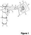
- the monitor arm support arrangement includes a support base 10, spacer tubes 11 with a pivot base 20 supported thereon, the pivot base 20 being rotatable through 360° with respect to the support base 10 by means of a bearing 12.
- An arm 30 is fixed by a pivot 32 to the post 34 extending from the pivot base 20.
- a mounting plate 40 having open ends 42, 44 and channelled sides 46, 48.
- the open end 44 is wider than the open end 42 creating a divergent channel between the sides 46, 48.
- the support base 10 may include means whereby it can be fixed, for example, removably, to a support surface (not shown) such as a desk, wall, floor, ceiling for stability, the fixing means being within the knowledge of a person skilled in the art.
- the mounting plate 40 is attached to the arm 30 through two pivoting mechanisms, a swivel head 50 and a ball pivot 60.
- the swivel head 50 is fixed to the arm 30 by a pin pivot, for example nut and bolt, 52.
- the swivel head 50 is a flange having a stepped head 54 cut to allow the head 50 to rotate about the stepped end 56 of the arm 30.
- the swivel head 50 can rotate through at least 180° in the plane of the monitor arm 30.
- a ball pivot 60 having a ball part 62 and a socket part 64 of a ball and socket joint.
- the socket 64 on the swivel head 50 mates with the ball 62 at the back 66 of the plate 40.
- the ball pivot 60 allows rotations of the plate 40 through the permitted angle of the ball pivot 60.
- rotation through plus or minus 40° in pitch and/or yaw is provided for the mounting plate 40 with respect to the longitudinal or roll axis of the swivel head 50.
- the arm 30 is supported by a gas spring 70 fixed at one end 72 to the arm 30 and fixed at the other end 74 of the gas spring 70 to the post 34 near the join of the pivot base 20 to the spacer 11.
- the arm 30 is partially hollowed to accommodate the gas spring 70 and to reduce the weight of the arm.
- the other end 74 of the gas spring 70 is supported by a pivoting attachment 76 to accommodate movement of the arm 30 in a vertical plane through the arm 30.
- the pivoting attachment 76 can move vertically to adjust the angle, and hence the weight bearing characteristics, of the gas spring 70.
- the gas spring 70 provides for damped movement of the arm 30.
- the friction provided by the bolt 32 and the bolt 52 provides respectively resistance to the motion of the arm 30 and the swivel head 50. The combination of these two factors allows the position of the plate 40 loaded by a panel display unit attached thereto to remain stationary or stable for any given position to which the arm 30 is moved.
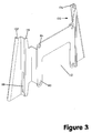
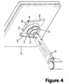
- a bracket 100 is shown allowing quick attaching and detaching of a planar monitor to the arm.
- a back plate 110 attaches the bracket 100 to a monitor 120 (see Fig.4) by fixtures 122 through holes 114.
- the bracket 100 has channels 102, 104 for sliding engagement on sides 46, 48 of mounting plate 40 with the separation of the channels 102, 104 matching the divergence of the sides 46, 48 (see Fig 4).
- the back plate 110 is spaced from the channels 102, 104 by stepped portion 116 to provide clearance for accommodating cabling between the mounting plate 40 and the monitor 120.
- the back plate 110 has cut-out 112 for allowing access to attach or detach the plugs of a monitor 120 once on the bracket 100.
- a lock 130 can be provided in the plate 40 to provide security for the monitor or planar visual display unit 120.
- the lock 130 has a tongue (not shown) which, when rotated to its locking position, engages in the slot 118 holding the mounting plate 40 and bracket 100 together.
- the components of the bracket 100 and the monitor arm such as the support base 10, spacers 11, the pivot base 20, the arm 30, or the plate 40 can be made of any suitable material such as metal or plastics material, within the knowledge of a person skilled in the art.
- the bearing components 12 such as between spacer 11 and the pivot base 20 can be made of nylon and the components of the ball pivot 60 between the swivel head 50 and the plate 40 can be made of materials within the knowledge of a person skilled in the art.
- the ball and socket joint as shown in Figures 2 and 4 is secured to the mounting plate 40 in any manner well known in the art, for example by fixtures 67, to the back 66 of the plate 40.
- An alternative arrangement is shown in Figure 5.
- the back 66 of mounting plate 40 has a truncated conical fixture 150 to which the socket part 64 of the ball and socket joint or ball pivot 60 is attached.
- adjustable fixtures 152 are located about the periphery 154 of socket part 64 and secure the socket part 64 to the fixture 150.
- Springs or similar resilient elements 156 are positioned about each fixture 152 between socket part 64 and conical fixture 150.
- Fixtures 152 may be screws or bolts, for example. Tightening or slackening of fixtures 152 against the restoring force of springs 156 allows adjustment of the pressure applied between the ball and socket components 62, 64 of the ball pivot 60 and thus of its frictional loading.
- Springs 156 also allow the pivot 60 to flex about directions within the plane of the plate 40 or of the planar VDU 120. This arrangement allows dampening of the motion of the pivot 60 and of the VDU held by the plate 40.
- Springs 156 may be coiled springs or may be leaf springs. Other forms of resilient means are contemplated within the knowledge of a person skilled in the art.
- More than one support arm 30 can be supported by the support base 10.
- Figure 6, shows the situation where two support arms 30, 30' are provided, each attached to their respective pivot base 20, 20', including posts 34, 34', and supporting respective VDU 120, 120'.
- Each of the features of the two supporting arrangements 200, 220 is substantially identical to those of the embodiments described above with respect to Figures 1-5.
- Each arm 30, 30' may support a VDU the same as the other or of a different size, weight or construction.
- the VDUs may face the same direction (as shown) or a different direction as required.
- the spacer means 11 may be used to space the pivot bases 20, 20' from the support base 12 or may be used to space the pivot bases 20, 20' apart.
Landscapes
- Engineering & Computer Science (AREA)
- General Engineering & Computer Science (AREA)
- Mechanical Engineering (AREA)
- Theoretical Computer Science (AREA)
- Computer Hardware Design (AREA)
- Human Computer Interaction (AREA)
- Physics & Mathematics (AREA)
- General Physics & Mathematics (AREA)
- Devices For Indicating Variable Information By Combining Individual Elements (AREA)
- Pivots And Pivotal Connections (AREA)
- Fittings On The Vehicle Exterior For Carrying Loads, And Devices For Holding Or Mounting Articles (AREA)
- Spinning Or Twisting Of Yarns (AREA)
Claims (15)
- Dispositif de support ajustable d'une unité de visualisation, le dispositif comportant un moyen pour fixer une unité de visualisation, le moyen de fixation (40) étant connecté à un bras (30) par l'intermédiaire d'un moyen d'orientation (50), le bras étant supporté sur une base de support (10), caractérisé en ce que le dispositif englobe une ou plusieurs bases de pivotement (20) supportées sur la base de support (10), la ou chaque base de pivotement (20) étant espacée de la base de support (10) et supportée sur un moyen de support (12), permettant la rotation libre de chacune desdites bases de pivotement (20) de 360° par rapport à ladite base de support (10), le bras (30) étant connecté au niveau d'une extrémité à une base de pivotement (20) et pouvant pivoter par rapport à celle-ci autour d'un axe horizontal, ledit bras (30) comportant un moyen amortisseur (70) pour amortir le déplacement dudit bras (30), le moyen de fixation d'une unité de visualisation comportant un moyen de montage (40, 50, 60) au niveau d'une extrémité libre du bras, ledit moyen de montage englobant le moyen d'orientation sous forme d'une tête à basculement (50) fixée par un moyen de pivot (52) au niveau de ladite extrémité libre dudit bras (30), ladite tête à basculement (50) supportant au niveau d'une extrémité distale par rapport audit moyen de pivot (52) un moyen de joint à rotule (62, 64) pour fixer une unité de visualisation (44).
- Dispositif de support d'une unité de visualisation selon la revendication 1, dans lequel ledit moyen de fixation peut tourner de 180° autour dudit moyen de pivot (52), de plus ou moins 40° dans une quelconque autre direction et de 360° autour de l'axe longitudinal dudit bras (30).
- Dispositif de support d'une unité de visualisation selon la revendication 1, dans lequel plusieurs bras de contrôle (30, 30') sont fixés sur ladite base de support (10) par l'intermédiaire de bases de pivotement respectives (20, 20').
- Dispositif selon la revendication 1, dans lequel ledit bras de contrôle (30) peut être soulevé ou abaissé de 110° dans un plan vertical traversant ledit bras (30), ledit moyen de montage pouvant tourner de 180° dans le plan dudit bras (30), de 360° autour de l'axe longitudinal dudit bras (30) et de plus ou moins 40° dans une quelconque autre direction, ledit bras (30) étant fixé sur ladite base de pivotement (20) par un moyen de pivotement du bras (32), ledit bras (30) étant supporté par un moyen élastique (70) fixé entre ladite base de pivotement (20) et ledit bras (30), ledit moyen élastique (70) et ledit moyen de pivotement du bras (32) permettant un déplacement amorti dudit bras (30), ledit bras (30) étant ainsi maintenu dans un état d'équilibre.
- Dispositif de support d'une unité de visualisation selon la revendication 4, dans lequel ledit moyen de pivotement du bras (32) est constitué par un bras pivotant, ledit moyen élastique (70) étant constitué par un ressort à gaz.
- Dispositif de support d'une unité de visualisation selon la revendication 5, dans lequel ledit moyen de fixation englobe une section de canal.
- Dispositif de support d'une unité de visualisation selon la revendication 6, dans lequel ladite section de canal englobe une partie de base et une paire de parois latérales verticales non parallèles (46, 48) pour supporter une console de montage (100) sur laquelle est fixée ladite unité de visualisation.
- Dispositif de support d'une unité de visualisation selon la revendication 7, dans lequel ladite console de montage (100) englobe une plaque arrière (110) fixant ladite console de montage (100) sur ladite unité de visualisation, une paire de canaux non parallèles (102, 104) destinés à s'engager dans lesdites parois latérale verticales non parallèles (46, 48) de ladite section de canal, et des parties de liaison respectives (116) établissant un espacement entre lesdits canaux (102, 104) de ladite console de montage (100) de ladite plaque arrière (110).
- Dispositif de support d'une unité de visualisation selon les revendications 5 ou 8, dans lequel ledit moyen de fixation est fixé de manière rigide sur un composant dudit moyen de joint à rotule (60).
- Dispositif de support d'une unité de visualisation selon les revendications 5 ou 8, dans lequel ledit moyen de fixation est fixé de manière élastique sur un composant dudit moyen de joint à rotule (60).
- Dispositif de support d'une unité de visualisation selon la revendication 10, dans lequel ledit composant est constitué par la partie de douille (64) dudit moyen de joint à rotule (60), ledit moyen de fixation étant fixé de manière élastique sur ladite partie de douille (64) par des moyens de fixation ajustables sollicités par ressort (152, 156).
- Dispositif de support d'une unité de visualisation selon la revendication 10, dans lequel ladite unité de visualisation est constituée par un écran d'affichage plat.
- Dispositif de support de plusieurs unités de visualisation englobant plusieurs bases de pivotement (20, 20'), chacune pouvant tourner par rapport à ladite base de support (10) et chacune comportant un bras (30, 30'), un moyen d'amortissement (70) et un moyen de montage selon l'une quelconque des revendications 1, 2 ou 4 à 12 pour supporter lesdites plusieurs unités de visualisation respectives.
- Dispositif de support d'une unité de visualisation selon l'une quelconque des revendications 1 à 12, englobant en outre un moyen d'espacement (11) pour établir un espace entre ladite base de pivotement (20) et ladite base de support (10) ou une autre base de pivotement (20').
- Dispositif de support d'une unité de visualisation selon la revendication 13, englobant en outre un moyen d'espacement (11) pour établir un espace entre ladite base de pivotement (20) et ladite base de support (10) ou une autre base de pivotement (20').
Applications Claiming Priority (5)
| Application Number | Priority Date | Filing Date | Title |
|---|---|---|---|
| AUPQ4126A AUPQ412699A0 (en) | 1999-11-18 | 1999-11-18 | Support arm for visual display unit |
| AUPQ412699 | 1999-11-18 | ||
| AUPQ912900 | 2000-08-02 | ||
| AUPQ9129A AUPQ912900A0 (en) | 2000-08-02 | 2000-08-02 | Support arm for visual display unit |
| PCT/AU2000/001388 WO2001035796A1 (fr) | 1999-11-18 | 2000-11-10 | Bras support pour terminal a ecran de visualisation |
Publications (3)
| Publication Number | Publication Date |
|---|---|
| EP1237444A1 EP1237444A1 (fr) | 2002-09-11 |
| EP1237444A4 EP1237444A4 (fr) | 2005-02-02 |
| EP1237444B1 true EP1237444B1 (fr) | 2007-01-03 |
Family
ID=25646205
Family Applications (1)
| Application Number | Title | Priority Date | Filing Date |
|---|---|---|---|
| EP00974177A Expired - Lifetime EP1237444B1 (fr) | 1999-11-18 | 2000-11-10 | Bras support pour terminal a ecran de visualisation |
Country Status (5)
| Country | Link |
|---|---|
| US (1) | US6554238B1 (fr) |
| EP (1) | EP1237444B1 (fr) |
| AT (1) | ATE349933T1 (fr) |
| DE (1) | DE60032802T2 (fr) |
| WO (1) | WO2001035796A1 (fr) |
Cited By (3)
| Publication number | Priority date | Publication date | Assignee | Title |
|---|---|---|---|---|
| CN101953156B (zh) * | 2008-01-07 | 2013-04-24 | 郭寿晚 | 显示装置用支架 |
| WO2024019193A1 (fr) * | 2022-07-21 | 2024-01-25 | 엘지전자 주식회사 | Dispositif d'affichage |
| WO2024085278A1 (fr) * | 2022-10-20 | 2024-04-25 | 엘지전자 주식회사 | Dispositif d'affichage |
Families Citing this family (200)
| Publication number | Priority date | Publication date | Assignee | Title |
|---|---|---|---|---|
| US5842672A (en) * | 1996-06-07 | 1998-12-01 | Ergotron, Inc. | Mounting system for flat panel display, keyboard and stand |
| US6343006B1 (en) | 1998-11-20 | 2002-01-29 | Jerry Moscovitch | Computer display screen system and adjustable screen mount, and swinging screens therefor |
| WO2000039493A1 (fr) | 1998-12-23 | 2000-07-06 | Jerry Moscovitch | Systeme d'ecran d'affichage d'ordinateur, monture d'ecran reglable, et ecrans pivotant associes |
| AU6462600A (en) * | 1999-08-23 | 2001-03-19 | Mass Engineered Design | Universal quick connector apparatus for an lcd monitor |
| WO2001035197A1 (fr) | 1999-11-12 | 2001-05-17 | Mass Engineered Design | Systeme lcd horizontal a trois ecrans |
| GB2360894B (en) * | 2000-03-30 | 2004-11-10 | Peter Thomas Bosson | Display device support system |
| US20030057810A1 (en) * | 2000-05-26 | 2003-03-27 | Brass Smith Inc. | Sneeze guards with lights |
| JP4639447B2 (ja) * | 2000-09-05 | 2011-02-23 | パナソニック株式会社 | 情報処理装置 |
| DE10047377A1 (de) * | 2000-09-25 | 2002-04-25 | Siemens Ag | Bildschirm-Arbeitsplatz mit zwei LCD-Bildschirmen |
| KR100377629B1 (ko) * | 2001-06-05 | 2003-03-26 | 엘지전자 주식회사 | 벽걸이용 디스플레이 장치의 각도 조절장치 |
| US20030098399A1 (en) * | 2001-06-13 | 2003-05-29 | Rodriguez Albert R. | Apparatus for supporting a model craft |
| US6435186B1 (en) * | 2001-08-17 | 2002-08-20 | Kurt Klemm | Anterior support device |
| US7422016B2 (en) * | 2001-08-17 | 2008-09-09 | Pilgrim Innovations, Llc | Anterior support device |
| US7624737B2 (en) * | 2001-08-17 | 2009-12-01 | Pilgrim Innovations, Llc | Anterior support device |
| DE20118841U1 (de) * | 2001-11-19 | 2003-04-03 | Novus Sträter GmbH, 58540 Meinerzhagen | System zur Bildung einer Standwand für Flachbildschirmgeräte |
| DE10205869B4 (de) * | 2002-02-13 | 2010-04-15 | Mavig Gmbh | Träger zum Tragen von zumindest einem Anzeigeapparat |
| US6874744B2 (en) * | 2002-02-25 | 2005-04-05 | Wacom Co., Ltd. | Stand for supporting a display in multiple orientations and a display used in combination with said stand |
| US7331551B2 (en) * | 2002-04-24 | 2008-02-19 | Innovative Office Products, Inc. | Multiple electronic device reorienting support |
| US6905101B1 (en) | 2002-06-11 | 2005-06-14 | Chief Manufacturing Inc. | Adjustable, self-balancing flat panel display mounting system |
| US20080054698A1 (en) * | 2002-06-26 | 2008-03-06 | Pilgrim Innovations, Llc | Combination twin adapter mounting plate and a pair of anterior supports |
| US20070289599A1 (en) * | 2002-06-26 | 2007-12-20 | Pilgrim Innovations, Llc | Anterior support device |
| TW527073U (en) * | 2002-06-28 | 2003-04-01 | Hannstar Display Corp | Three-axial hinge of a display device |
| GB2390800B (en) * | 2002-07-16 | 2005-10-26 | Colebrook Bosson Saunders Prod | Support for electrical display device |
| US7086192B2 (en) * | 2002-08-02 | 2006-08-08 | Deros Mark A | Adjustable gun rest apparatus |
| US6695270B1 (en) * | 2002-08-15 | 2004-02-24 | Ole Falk Smed | Flat panel display system |
| US7243892B2 (en) * | 2003-01-09 | 2007-07-17 | Csav, Inc. | Articulated mount |
| US7152836B2 (en) | 2003-01-09 | 2006-12-26 | Csav, Inc. | Adjustable tilt mount |
| US7121518B2 (en) * | 2003-01-24 | 2006-10-17 | Hovde Arthur M | Portable workstation and carrying case |
| JP4167506B2 (ja) * | 2003-02-03 | 2008-10-15 | 株式会社村上開明堂 | ディスプレイの方向調整装置 |
| ATE350618T1 (de) | 2003-02-03 | 2007-01-15 | Bang & Olufsen As | Kippmechanismus |
| US20040262474A1 (en) * | 2003-04-22 | 2004-12-30 | Boks Michael J. | Flat screen monitor support system |
| US7028961B1 (en) * | 2003-05-30 | 2006-04-18 | Csav, Inc. | Self-balancing adjustable flat panel mounting system |
| KR20030086551A (ko) * | 2003-10-22 | 2003-11-10 | 금호석유화학 주식회사 | 식물로부터의 아넥신을 인코드하는 핵산 분자 |
| KR100753607B1 (ko) * | 2003-10-27 | 2007-08-30 | 삼성전자주식회사 | 디스플레이장치 |
| TWM254544U (en) * | 2003-10-29 | 2005-01-01 | Chin-Chih Lin | Pivot shaft structure for flat displaying device |
| EP1530117A1 (fr) * | 2003-11-06 | 2005-05-11 | Dicom AG | Ecran plat modulaire |
| USD507477S1 (en) | 2004-01-02 | 2005-07-19 | Decade Industries, Inc. | Display mount |
| USD494978S1 (en) | 2004-01-02 | 2004-08-24 | Decade Industries, Inc. | Display mount |
| USD494596S1 (en) | 2004-01-02 | 2004-08-17 | Decade Industries, Inc. | Display mount |
| USD496367S1 (en) | 2004-01-02 | 2004-09-21 | Decade Industries, Inc. | Display mount |
| USD495713S1 (en) | 2004-01-02 | 2004-09-07 | Decade Industries, Inc. | Display mount |
| USD493800S1 (en) | 2004-01-02 | 2004-08-03 | Decade Industries, Inc. | Display mount |
| USD495714S1 (en) | 2004-01-02 | 2004-09-07 | Decade Industries, Inc. | Display mount |
| CA2594801A1 (fr) * | 2004-01-12 | 2005-07-21 | Jerry Moscovitch | Appareil et procede pour l'adjonction d'ecran a un systeme d'affichage |
| USD505858S1 (en) * | 2004-03-02 | 2005-06-07 | Peerless Industries, Inc. | Wall mounting system |
| KR100531314B1 (ko) * | 2004-03-16 | 2005-11-29 | 엘지전자 주식회사 | 영상표시장치 |
| TWD104582S1 (zh) * | 2004-03-30 | 2005-05-11 | 林敬智 | 全方位懸臂 |
| KR100586983B1 (ko) * | 2004-05-21 | 2006-06-08 | 삼성전자주식회사 | 모니터장치 |
| US7677182B2 (en) * | 2004-05-27 | 2010-03-16 | Steelcase Development Corporation | Two person work environment |
| US7708240B2 (en) * | 2004-07-29 | 2010-05-04 | Hewlett-Packard Development Company, L.P. | Computer docking system |
| KR100651938B1 (ko) * | 2004-08-16 | 2006-12-06 | 엘지전자 주식회사 | 영상 배향 제어장치, 방법 및 매체 |
| US20060065800A1 (en) * | 2004-09-29 | 2006-03-30 | Jeff Bremmon | Universal mount for flat panel displays |
| US20060065795A1 (en) * | 2004-09-30 | 2006-03-30 | Compx International | Support for flat monitors |
| US7210662B2 (en) * | 2004-12-30 | 2007-05-01 | Hannspree, Inc. | Display device with a foldable suspension arm |
| USD522009S1 (en) * | 2005-02-14 | 2006-05-30 | Hoolin Research Company Limited | Bracing frame |
| US7673838B2 (en) * | 2005-02-16 | 2010-03-09 | Innovative Office Products, Inc. | Quick release assembly for an electronic device |
| EP1703195A1 (fr) * | 2005-03-18 | 2006-09-20 | Market Link USA, Inc. | Support d'écran de visualisation |
| USD529033S1 (en) * | 2005-04-11 | 2006-09-26 | Chin-Jui Hung | Extension mount for a flat panel monitor |
| US7264212B2 (en) * | 2005-05-20 | 2007-09-04 | Chin-Jui Hung | Monitor-holding device |
| US8794579B2 (en) | 2005-06-03 | 2014-08-05 | Steelcase, Inc. | Support arm assembly |
| US20070084978A1 (en) * | 2005-10-17 | 2007-04-19 | Martin Randall W | Multiple-display mount |
| US7641163B2 (en) | 2005-10-21 | 2010-01-05 | Peerless Industries, Inc. | Tilt mounting system |
| JP4796837B2 (ja) * | 2005-12-27 | 2011-10-19 | Necディスプレイソリューションズ株式会社 | ディスプレイと支持具の連結構造およびディスプレイ |
| US20070153459A1 (en) * | 2006-01-04 | 2007-07-05 | Jim Wohlford | Mounting system for flat panel electronic display |
| US7316377B2 (en) * | 2006-01-24 | 2008-01-08 | Ole Falk Smed | Flat panel monitor mount with low profile ball and socket swivel and tilter mount |
| US20070246629A1 (en) * | 2006-04-24 | 2007-10-25 | Z-Line Designs | Articulating swivel mounting mechanism |
| USD543211S1 (en) * | 2006-04-26 | 2007-05-22 | Bretford Manufacturing, Inc. | Wishbone support arm |
| GB0610754D0 (en) * | 2006-06-01 | 2006-07-12 | Tech Internat Ltd B | Bracket |
| US7997211B2 (en) * | 2006-06-12 | 2011-08-16 | Steelcase Inc. | Wall mounted workstation |
| USD558560S1 (en) * | 2006-07-24 | 2008-01-01 | Peerless Industries, Inc. | Articulating mount |
| USD559087S1 (en) * | 2006-07-25 | 2008-01-08 | Peerless Industries, Inc. | Articulating mount |
| USD558561S1 (en) * | 2006-07-26 | 2008-01-01 | Peerless Industries, Inc. | Articulating mount |
| USD562113S1 (en) * | 2006-08-03 | 2008-02-19 | Peerless Industries, Inc. | Articulating mount unit |
| USD558562S1 (en) * | 2006-08-08 | 2008-01-01 | Peerless Industries, Inc. | Articulating mount unit |
| USD558563S1 (en) * | 2006-08-10 | 2008-01-01 | Peerless Industries, Inc. | Articulating mount |
| USD559088S1 (en) * | 2006-08-11 | 2008-01-08 | Peerless Industries, Inc. | Articulating mount |
| USD558564S1 (en) * | 2006-08-11 | 2008-01-01 | Peerless Industries, Inc. | Articulating mount |
| TWM307256U (en) * | 2006-08-16 | 2007-03-01 | Jarllytec Co Ltd | Fastening structure with rapid stevedoring features |
| USD563774S1 (en) * | 2006-08-28 | 2008-03-11 | Csav, Inc. | Mount for article |
| US20080073471A1 (en) * | 2006-09-25 | 2008-03-27 | Beger Lawrence J | Two in One Video Monitor Mount |
| JP4228010B2 (ja) * | 2006-09-29 | 2009-02-25 | Necエンジニアリング株式会社 | テレビ会議装置 |
| USD577730S1 (en) * | 2006-10-11 | 2008-09-30 | Ionic B.V. | Load bearing structure |
| US8000090B2 (en) | 2006-11-16 | 2011-08-16 | Jerry Moscovitch | Multi-monitor support structure |
| WO2008083396A1 (fr) | 2007-01-03 | 2008-07-10 | Milestone Av Technologies, Inc. | Monture de dispositif ayant un axe de basculement pouvant être sélectivement positionné |
| US7866622B2 (en) * | 2007-01-05 | 2011-01-11 | Milestone Av Technologies Llc | In-wall mount |
| JP2010515937A (ja) * | 2007-01-05 | 2010-05-13 | マイルストーン エイブイ テクノロジーズ エルエルシー | フラットパネル電子ディスプレイの傾動位置決め用壁回避自己バランスマウント |
| US20090173847A1 (en) * | 2007-01-24 | 2009-07-09 | Wolfgang Dittmer | Accessory Holder |
| US7922132B2 (en) * | 2007-01-24 | 2011-04-12 | Humanscale Corporation | Accessory holder |
| US7891622B1 (en) | 2007-02-02 | 2011-02-22 | Peerless Industries, Inc. | Adjustable tilt mounting system |
| USD574698S1 (en) | 2007-02-21 | 2008-08-12 | Csav, Inc. | Tilt bracket for display mount |
| US20080221930A1 (en) | 2007-03-09 | 2008-09-11 | Spacelabs Medical, Inc. | Health data collection tool |
| USD566444S1 (en) | 2007-03-14 | 2008-04-15 | Csav, Inc. | Wall interface for display mount |
| US7593219B2 (en) * | 2007-04-26 | 2009-09-22 | Hewlett-Packard Development Company, L.P. | Display support system and method |
| US8363170B2 (en) * | 2007-06-14 | 2013-01-29 | Panasonic Automotive Systems Company Of America, Division Of Panasonic Corporation Of North America | Dual display multi-modal vehicle infotainment system |
| WO2009006414A1 (fr) * | 2007-06-29 | 2009-01-08 | Draeger Medical Systems, Inc. | Montage inclinable et pivotant pour moniteurs et autres dispositifs |
| TWM324949U (en) * | 2007-07-18 | 2008-01-01 | Ming-Hsien Tom Huang | Bracket device |
| USD595723S1 (en) | 2007-11-09 | 2009-07-07 | Milestone Av Technologies Llc | Pivot arm assembly for mounting an electronic display |
| SE532789C2 (sv) * | 2007-11-14 | 2010-04-13 | Cgm Ab | Bord med synkroniserade bildskärmar |
| TWM336654U (en) * | 2007-11-22 | 2008-07-11 | ming-xian Huang | Multi-screen supporting frame |
| USD587710S1 (en) * | 2007-12-28 | 2009-03-03 | Evga Corporation | Dual display monitor |
| USD589958S1 (en) * | 2007-12-28 | 2009-04-07 | Evga Corporation | Dual display monitor |
| USD587711S1 (en) * | 2007-12-28 | 2009-03-03 | Evga Corporation | Dual display monitor |
| USD589511S1 (en) * | 2007-12-28 | 2009-03-31 | Evga Corporation | Dual display monitor |
| USD589959S1 (en) * | 2007-12-28 | 2009-04-07 | Evga Corporation | Dual display monitor |
| US8958200B2 (en) | 2008-01-04 | 2015-02-17 | Milestone Av Technologies Llc | Display mount with post-installation adjustment features |
| EP2238749A4 (fr) * | 2008-01-04 | 2011-07-27 | Milestone Av Technologies Llc | Support mural pour écran plat |
| USD595702S1 (en) | 2008-01-04 | 2009-07-07 | Milestone Av Technologies Llc | Tilt adjustable display interface bracket |
| US7823847B2 (en) * | 2008-01-04 | 2010-11-02 | Milestone Av Technologies Llc | Display mount with post-installation adjustment features |
| US20090235509A1 (en) * | 2008-03-20 | 2009-09-24 | Beger Lawrence J | Tool-Less Television Stand |
| US8256047B2 (en) * | 2008-04-03 | 2012-09-04 | Klemm Kurt W | Combination treatment device and an anterior support device |
| US20090249551A1 (en) * | 2008-04-03 | 2009-10-08 | Pilgrim Innovations, Llc | Combination treatment device and an anterior support device |
| CN102177386B (zh) * | 2008-08-11 | 2014-11-26 | 欧特科技有限公司 | 可调节支架 |
| US8448906B2 (en) | 2008-08-21 | 2013-05-28 | Knoll, Inc. | Support apparatus |
| CN102160372B (zh) | 2008-09-02 | 2015-01-07 | 里程碑视听科技有限责任公司 | 用于平板电子显示器的小体积安装件 |
| CN101684882B (zh) * | 2008-09-25 | 2012-07-18 | 鸿富锦精密工业(深圳)有限公司 | 升降机构 |
| US8042774B2 (en) * | 2008-10-03 | 2011-10-25 | Panduit Corp. | Control panel mount having one or more strain relief features |
| CA2685060A1 (fr) * | 2008-11-07 | 2010-05-07 | Jerry Moscovitch | Dispositif repliable permettant de soutenir plusieurs moniteurs d'ordinateur |
| USD627787S1 (en) | 2009-01-07 | 2010-11-23 | Milestone Av Technologies Llc | Display mount with single articulating arm |
| USD620943S1 (en) | 2009-01-07 | 2010-08-03 | Milestone Av Technologies Llc | Single arm display mount |
| CN102273197B (zh) | 2009-01-07 | 2014-10-01 | 里程碑视听科技有限责任公司 | 具有可调整位置倾斜轴的显示器支架 |
| USD606548S1 (en) | 2009-01-21 | 2009-12-22 | Knoll, Inc. | Support arm |
| US20100128423A1 (en) * | 2009-03-10 | 2010-05-27 | Jerry Moscovitch | Stand for a Plurality of Electronic Devices |
| US8944393B2 (en) * | 2009-04-08 | 2015-02-03 | Nec Display Solutions, Ltd. | Fixing structure and fixing method of multi-screen display unit |
| US20100271287A1 (en) * | 2009-04-24 | 2010-10-28 | Christopher Bourne | Dual-display transportable media cart |
| USD624084S1 (en) * | 2009-06-12 | 2010-09-21 | Steelcase Inc. | Support |
| USD633454S1 (en) * | 2009-08-06 | 2011-03-01 | Nec Display Solutions, Ltd. | Display |
| USD624513S1 (en) * | 2009-08-06 | 2010-09-28 | Nec Display Solutions, Ltd. | Display |
| USD615054S1 (en) * | 2009-08-20 | 2010-05-04 | Tandberg Telecom As | Double monitor and stand |
| USD610381S1 (en) | 2009-10-05 | 2010-02-23 | Peerless Industries, Inc. | Cover |
| USD614896S1 (en) | 2009-10-05 | 2010-05-04 | Peerless Industries, Inc. | Ceiling mount |
| US9086313B2 (en) * | 2009-10-16 | 2015-07-21 | Spacelabs Healthcare Llc | Integrated, extendable anesthesia system |
| US9604020B2 (en) | 2009-10-16 | 2017-03-28 | Spacelabs Healthcare Llc | Integrated, extendable anesthesia system |
| MX2012004462A (es) | 2009-10-16 | 2012-06-27 | Spacelabs Healthcare Llc | Tubo de flujo de luz mejorado. |
| US8814224B2 (en) * | 2009-11-11 | 2014-08-26 | Hoffman Enclosures, Inc. | Enclosure suspension system with compression fitting |
| US7738245B1 (en) | 2009-11-23 | 2010-06-15 | Peerless Industries, Inc. | Display mount |
| KR101698309B1 (ko) * | 2010-01-07 | 2017-01-20 | 삼성전자주식회사 | 디스플레이장치용 지지장치 |
| BR112012023514B1 (pt) | 2010-03-21 | 2021-08-10 | Spacelabs Healthcare, Llc | Sistema de monitoração de beira de leito de múltiplas exibições |
| USD632301S1 (en) * | 2010-03-24 | 2011-02-08 | Nec Display Solutions, Ltd. | Display |
| US8973532B2 (en) * | 2010-04-14 | 2015-03-10 | Current-Usa, Inc. | Aquarium light fixture with hinge |
| US8544805B2 (en) | 2010-05-28 | 2013-10-01 | VirGiaN, LLC | Mounting system for removably securing an object to a surface |
| USD652423S1 (en) | 2010-06-08 | 2012-01-17 | Knoll, Inc. | Support arm |
| US9074721B2 (en) | 2010-06-09 | 2015-07-07 | Alex Lau | Support system |
| US9316346B2 (en) | 2010-06-09 | 2016-04-19 | Colebrook Bosson Saunders (Products) Limited | Support system |
| US8342462B2 (en) | 2010-06-11 | 2013-01-01 | Knoll, Inc. | Support apparatus |
| USD634745S1 (en) * | 2010-08-05 | 2011-03-22 | Samsung Electronics Co., Ltd. | LCD monitor |
| USD684982S1 (en) | 2010-08-11 | 2013-06-25 | Colebrook Bosson Saunders (Products) Limited | Display support with indicator window |
| USD635008S1 (en) | 2010-08-13 | 2011-03-29 | VirGiaN, LLC | Mounting system |
| USD658972S1 (en) | 2010-08-13 | 2012-05-08 | VirGiaN, LLC | Mounting clip |
| TWM396551U (en) | 2010-09-03 | 2011-01-11 | ming-xian Huang | Screen holder capable of adjusting screen angle |
| JP5193264B2 (ja) * | 2010-11-04 | 2013-05-08 | タキゲン製造株式会社 | システムレール及びシステムレールユニット |
| BR112013012329B1 (pt) | 2010-11-19 | 2021-05-04 | Spacelabs Healthcare, Llc | Dispositivo de tela para uso em um sistema de monitoramento de paciente e sistema de monitoramento de paciente |
| WO2012083281A1 (fr) * | 2010-12-17 | 2012-06-21 | Spacelabs Heal Thcare. Llc | Système de montage de type chemin de glissement et pivot pour affichages d'appareils d'anesthésie |
| US8403430B2 (en) | 2011-02-07 | 2013-03-26 | Brass Smith, Llc | Adjustable food shield |
| USD651210S1 (en) * | 2011-02-23 | 2011-12-27 | Roslynn Bryant | Adjustable multi-screen display monitor |
| TWI386150B (zh) * | 2011-03-03 | 2013-02-11 | Aopen Inc | 端點銷售系統架及端點銷售系統 |
| US9629566B2 (en) | 2011-03-11 | 2017-04-25 | Spacelabs Healthcare Llc | Methods and systems to determine multi-parameter managed alarm hierarchy during patient monitoring |
| USD701569S1 (en) * | 2011-03-22 | 2014-03-25 | Matthew Fagan | Pantograph arm set |
| US20130126685A1 (en) * | 2011-05-19 | 2013-05-23 | Ergotron, Inc. | Display Mounting Interface System and Method |
| US20130112828A1 (en) | 2011-06-07 | 2013-05-09 | Knoll, Inc. | Support Apparatus for Display Devices and Other Objects |
| USD654503S1 (en) | 2011-06-08 | 2012-02-21 | Knoll, Inc. | Support arm |
| TWI408302B (zh) * | 2011-06-17 | 2013-09-11 | Aopen Inc | 懸掛模組 |
| USD674807S1 (en) | 2011-09-13 | 2013-01-22 | Innovative Office Products, Inc. | Quick-release display adapter |
| US8651444B2 (en) | 2011-09-23 | 2014-02-18 | Knoll, Inc. | Friction adjustment mechanism for a support apparatus |
| USD663307S1 (en) | 2011-11-17 | 2012-07-10 | Knoll, Inc. | Support apparatus |
| US8936223B1 (en) | 2012-05-03 | 2015-01-20 | Andrew H. McGrath | Adjustable bracket assembly |
| FR2995091B1 (fr) * | 2012-08-28 | 2015-08-14 | Commissariat Energie Atomique | Dispositif d'imagerie a grand angle de vue |
| CN202939922U (zh) * | 2012-10-16 | 2013-05-15 | 深圳市奥拓电子股份有限公司 | 一种显示屏快速拼接装置 |
| USD708158S1 (en) | 2012-10-31 | 2014-07-01 | Charles Nolan Minyard | Three monitor system |
| US9163433B2 (en) | 2012-10-31 | 2015-10-20 | Invue Security Products Inc. | Display stand for a tablet computer |
| CN103002685B (zh) * | 2012-11-16 | 2015-11-25 | 京东方科技集团股份有限公司 | 一种封装外壳、底座及显示装置 |
| US10987026B2 (en) | 2013-05-30 | 2021-04-27 | Spacelabs Healthcare Llc | Capnography module with automatic switching between mainstream and sidestream monitoring |
| US10058198B2 (en) | 2013-06-18 | 2018-08-28 | Brass Smith Innovations, Llc | Food service equipment and systems |
| USD762652S1 (en) * | 2013-08-15 | 2016-08-02 | Siemens Aktiengesellschaft | Mounting system for monitors |
| US9089216B2 (en) * | 2013-08-29 | 2015-07-28 | Top Victory Investment Ltd. | Holder assembly |
| TWI549513B (zh) * | 2014-04-23 | 2016-09-11 | 鴻海精密工業股份有限公司 | 螢幕壁掛結構 |
| US9400083B2 (en) | 2014-04-24 | 2016-07-26 | Knoll, Inc. | Support apparatus for multiple display devices |
| TWI547172B (zh) * | 2014-09-03 | 2016-08-21 | 鴻海精密工業股份有限公司 | 螢幕壁掛結構 |
| US9782022B2 (en) | 2015-02-12 | 2017-10-10 | Brass Smith Llc | Adjustable food shield with detents |
| USD756759S1 (en) | 2015-02-18 | 2016-05-24 | Brass Smith Llc | Support column for a food shield |
| US9454917B1 (en) * | 2015-09-30 | 2016-09-27 | Todd S. King | Display wall mount |
| EP3272193A4 (fr) | 2015-09-30 | 2018-06-27 | InVue Security Products, Inc. | Chargeur en série, coque et station d'accueil pour dispositifs électroniques portables |
| US9933107B2 (en) * | 2015-09-30 | 2018-04-03 | Todd S. King | Display wall mount |
| US10529260B2 (en) * | 2015-12-29 | 2020-01-07 | Christie Digital Systems Usa, Inc. | System for mounting a plurality of display units |
| TWM523265U (zh) * | 2016-01-04 | 2016-06-01 | Chen Source Inc | 螢幕之支架裝置 |
| DE112016006208T5 (de) * | 2016-01-12 | 2018-09-20 | Yamaha Hatsudoki Kabushiki Kaisha | Montagezielarbeitsvorrichtung |
| NL2016954B1 (en) * | 2016-06-13 | 2017-12-21 | Vlaar Innovations B V | Monitor arm coupling unit for coupling a flat panel display monitor to an end of a monitor arm of a monitor arm stand, and monitor arm stand including such a monitor coupling unit |
| US10520131B2 (en) * | 2016-09-30 | 2019-12-31 | Innovative Office Products, Llc | Pole arm system with stackable mount cup |
| US10101767B2 (en) * | 2017-04-18 | 2018-10-16 | Genesco Sports Enterprises, Inc. | Powered electronic display awning |
| US10794530B2 (en) * | 2017-11-23 | 2020-10-06 | Syncmold Enterprise Corp. | Rotating module |
| CN108626554A (zh) * | 2018-07-17 | 2018-10-09 | 深圳市洲明科技股份有限公司 | 连接装置和显示屏 |
| US10485340B1 (en) | 2018-10-23 | 2019-11-26 | Vincent Butler | Media system stand |
| GB2600840B (en) | 2019-06-26 | 2023-12-27 | Spacelabs Healthcare L L C | Using data from a body worn sensor to modify monitored physiological data |
| US11668431B2 (en) | 2020-04-27 | 2023-06-06 | Joshua Gardner Gilligan | Display mounting system |
| US11849552B2 (en) * | 2021-05-06 | 2023-12-19 | Manufacturing Design Solutions | Adjustable free-standing support for a data display monitor |
| JP7639182B2 (ja) * | 2021-07-21 | 2025-03-04 | エルジー エレクトロニクス インコーポレイティド | ディスプレイデバイス |
| US12007804B2 (en) * | 2022-06-13 | 2024-06-11 | Oxti Pte Ltd | Display fine-adjustment device |
| CN117071915B (zh) * | 2023-08-07 | 2025-12-26 | 河南豫美建设工程检测有限公司 | 一种钢网架螺栓球节点安装装置及质量检测方法 |
| WO2025160216A1 (fr) | 2024-01-23 | 2025-07-31 | Videndum Production Solutions Inc. | Ensemble d'éclairage |
| US20250257842A1 (en) * | 2024-02-09 | 2025-08-14 | Bloomberg Finance L.P. | Monitor stand with folding mounting brackets |
| USD1107718S1 (en) | 2024-02-09 | 2025-12-30 | Bloomberg Finance L.P. | Monitor stand |
Family Cites Families (12)
| Publication number | Priority date | Publication date | Assignee | Title |
|---|---|---|---|---|
| BE537726A (fr) * | 1954-04-29 | |||
| US4768744A (en) * | 1986-08-27 | 1988-09-06 | Richard Leeds | Apparatus for supporting a load in a dynamically balanced condition |
| US4836486A (en) * | 1987-04-16 | 1989-06-06 | Anthro Corporation | Adjustable support |
| US5505424A (en) | 1994-08-04 | 1996-04-09 | Health Care Information Corp. | Swivel support for an article |
| US5709360A (en) | 1994-09-30 | 1998-01-20 | Rosen; John B. | Ratcheting articulable monitor support and presentation device |
| US5876008A (en) | 1995-01-17 | 1999-03-02 | Ergotron, Inc. | Suspension system for video monitor or other equipment |
| US5687939A (en) * | 1996-04-26 | 1997-11-18 | Moscovitch; Jerry | Dual display system |
| US5751548A (en) | 1996-05-13 | 1998-05-12 | International Business Machines Corporation | Docking station for a portable computer providing rotational movement of the computer's viewable screen in three different planes |
| US5842672A (en) | 1996-06-07 | 1998-12-01 | Ergotron, Inc. | Mounting system for flat panel display, keyboard and stand |
| DE19638388A1 (de) * | 1996-09-19 | 1998-04-02 | Bayerische Motoren Werke Ag | Haltevorrichtung zum Positionieren eines Geräts, insbesondere eines Meß- oder Anzeigegeräts in einem Kraftfahrzeug |
| US6138970A (en) * | 1999-05-07 | 2000-10-31 | Sohrt; Thomas M. | Universally adjustable mounting system |
| US6189842B1 (en) * | 1999-06-21 | 2001-02-20 | Palo Alto Design Group | Tilt and swivel adjustment of flat panel display having detents for landscape and portrait positions and kickout for preventing contact between flat panel display and base |
-
2000
- 2000-11-10 DE DE60032802T patent/DE60032802T2/de not_active Expired - Fee Related
- 2000-11-10 AT AT00974177T patent/ATE349933T1/de not_active IP Right Cessation
- 2000-11-10 WO PCT/AU2000/001388 patent/WO2001035796A1/fr not_active Ceased
- 2000-11-10 US US10/111,435 patent/US6554238B1/en not_active Expired - Fee Related
- 2000-11-10 EP EP00974177A patent/EP1237444B1/fr not_active Expired - Lifetime
Cited By (3)
| Publication number | Priority date | Publication date | Assignee | Title |
|---|---|---|---|---|
| CN101953156B (zh) * | 2008-01-07 | 2013-04-24 | 郭寿晚 | 显示装置用支架 |
| WO2024019193A1 (fr) * | 2022-07-21 | 2024-01-25 | 엘지전자 주식회사 | Dispositif d'affichage |
| WO2024085278A1 (fr) * | 2022-10-20 | 2024-04-25 | 엘지전자 주식회사 | Dispositif d'affichage |
Also Published As
| Publication number | Publication date |
|---|---|
| EP1237444A4 (fr) | 2005-02-02 |
| EP1237444A1 (fr) | 2002-09-11 |
| US6554238B1 (en) | 2003-04-29 |
| DE60032802T2 (de) | 2007-10-11 |
| ATE349933T1 (de) | 2007-01-15 |
| DE60032802D1 (de) | 2007-02-15 |
| WO2001035796A1 (fr) | 2001-05-25 |
Similar Documents
| Publication | Publication Date | Title |
|---|---|---|
| EP1237444B1 (fr) | Bras support pour terminal a ecran de visualisation | |
| US7316377B2 (en) | Flat panel monitor mount with low profile ball and socket swivel and tilter mount | |
| EP1754928B1 (fr) | Dispositif d'inclinaison | |
| JP5457172B2 (ja) | ディスプレイ取付け装置 | |
| US8596599B1 (en) | Apparatus for mounting a plurality of monitors having adjustable distance to a viewer | |
| US8777172B2 (en) | Support apparatus for display devices and other objects | |
| US7513474B2 (en) | Systems and methods for mounting flat panel video displays | |
| US6102348A (en) | Appliance mounting device | |
| US7995332B2 (en) | Support structure for two or more flat panel devices | |
| AU744414B2 (en) | Mounting system for flat panel display or keyboard | |
| US7878476B2 (en) | Apparatus for mounting a plurality of monitors having adjustable distance to a viewer | |
| US6575419B1 (en) | Universal support system for displays | |
| US7487944B2 (en) | Flat screen monitor desktop support | |
| US20070023593A1 (en) | Flat panel display mounting apparatus and system | |
| US20080068784A1 (en) | Moveable Display Mount | |
| WO2007032781A1 (fr) | Systeme de montage universel pour ecran plat | |
| US20110101179A1 (en) | Tv support structure with latching mechanism | |
| JP5589118B2 (ja) | 可変式ディスプレイスタンドのシステム及び方法 | |
| US7290888B2 (en) | Projection system | |
| US20100133402A1 (en) | Visual display unit mount | |
| US20100096515A1 (en) | Convertible Display Stand System and Method | |
| AU781167B2 (en) | Support arm for visual display unit | |
| US20030173476A1 (en) | Stable support system for displays | |
| US20050230590A1 (en) | Flat panel display ceiling mount | |
| WO2023215297A1 (fr) | Appareil de montage d'écran simple ou double |
Legal Events
| Date | Code | Title | Description |
|---|---|---|---|
| PUAI | Public reference made under article 153(3) epc to a published international application that has entered the european phase |
Free format text: ORIGINAL CODE: 0009012 |
|
| 17P | Request for examination filed |
Effective date: 20020618 |
|
| AK | Designated contracting states |
Kind code of ref document: A1 Designated state(s): AT BE CH CY DE DK ES FI FR GB GR IE IT LI LU MC NL PT SE TR |
|
| AX | Request for extension of the european patent |
Free format text: AL;LT;LV;MK;RO;SI |
|
| A4 | Supplementary search report drawn up and despatched |
Effective date: 20041221 |
|
| RIC1 | Information provided on ipc code assigned before grant |
Ipc: 7F 16M 11/04 B Ipc: 7A 47B 96/00 A Ipc: 7H 04N 5/64 B Ipc: 7A 47B 97/00 B |
|
| GRAP | Despatch of communication of intention to grant a patent |
Free format text: ORIGINAL CODE: EPIDOSNIGR1 |
|
| GRAS | Grant fee paid |
Free format text: ORIGINAL CODE: EPIDOSNIGR3 |
|
| GRAA | (expected) grant |
Free format text: ORIGINAL CODE: 0009210 |
|
| AK | Designated contracting states |
Kind code of ref document: B1 Designated state(s): AT BE CH CY DE DK ES FI FR GB GR IE IT LI LU MC NL PT SE TR |
|
| PG25 | Lapsed in a contracting state [announced via postgrant information from national office to epo] |
Ref country code: AT Free format text: LAPSE BECAUSE OF FAILURE TO SUBMIT A TRANSLATION OF THE DESCRIPTION OR TO PAY THE FEE WITHIN THE PRESCRIBED TIME-LIMIT Effective date: 20070103 Ref country code: FI Free format text: LAPSE BECAUSE OF FAILURE TO SUBMIT A TRANSLATION OF THE DESCRIPTION OR TO PAY THE FEE WITHIN THE PRESCRIBED TIME-LIMIT Effective date: 20070103 Ref country code: NL Free format text: LAPSE BECAUSE OF FAILURE TO SUBMIT A TRANSLATION OF THE DESCRIPTION OR TO PAY THE FEE WITHIN THE PRESCRIBED TIME-LIMIT Effective date: 20070103 Ref country code: LI Free format text: LAPSE BECAUSE OF FAILURE TO SUBMIT A TRANSLATION OF THE DESCRIPTION OR TO PAY THE FEE WITHIN THE PRESCRIBED TIME-LIMIT Effective date: 20070103 Ref country code: CH Free format text: LAPSE BECAUSE OF FAILURE TO SUBMIT A TRANSLATION OF THE DESCRIPTION OR TO PAY THE FEE WITHIN THE PRESCRIBED TIME-LIMIT Effective date: 20070103 Ref country code: DK Free format text: LAPSE BECAUSE OF FAILURE TO SUBMIT A TRANSLATION OF THE DESCRIPTION OR TO PAY THE FEE WITHIN THE PRESCRIBED TIME-LIMIT Effective date: 20070103 |
|
| REG | Reference to a national code |
Ref country code: GB Ref legal event code: FG4D |
|
| REF | Corresponds to: |
Ref document number: 60032802 Country of ref document: DE Date of ref document: 20070215 Kind code of ref document: P |
|
| REG | Reference to a national code |
Ref country code: IE Ref legal event code: FG4D |
|
| PG25 | Lapsed in a contracting state [announced via postgrant information from national office to epo] |
Ref country code: SE Free format text: LAPSE BECAUSE OF FAILURE TO SUBMIT A TRANSLATION OF THE DESCRIPTION OR TO PAY THE FEE WITHIN THE PRESCRIBED TIME-LIMIT Effective date: 20070403 |
|
| PG25 | Lapsed in a contracting state [announced via postgrant information from national office to epo] |
Ref country code: ES Free format text: LAPSE BECAUSE OF FAILURE TO SUBMIT A TRANSLATION OF THE DESCRIPTION OR TO PAY THE FEE WITHIN THE PRESCRIBED TIME-LIMIT Effective date: 20070414 |
|
| PG25 | Lapsed in a contracting state [announced via postgrant information from national office to epo] |
Ref country code: PT Free format text: LAPSE BECAUSE OF FAILURE TO SUBMIT A TRANSLATION OF THE DESCRIPTION OR TO PAY THE FEE WITHIN THE PRESCRIBED TIME-LIMIT Effective date: 20070604 |
|
| NLV1 | Nl: lapsed or annulled due to failure to fulfill the requirements of art. 29p and 29m of the patents act | ||
| REG | Reference to a national code |
Ref country code: CH Ref legal event code: PL |
|
| EN | Fr: translation not filed | ||
| PLBE | No opposition filed within time limit |
Free format text: ORIGINAL CODE: 0009261 |
|
| STAA | Information on the status of an ep patent application or granted ep patent |
Free format text: STATUS: NO OPPOSITION FILED WITHIN TIME LIMIT |
|
| 26N | No opposition filed |
Effective date: 20071005 |
|
| PG25 | Lapsed in a contracting state [announced via postgrant information from national office to epo] |
Ref country code: BE Free format text: LAPSE BECAUSE OF FAILURE TO SUBMIT A TRANSLATION OF THE DESCRIPTION OR TO PAY THE FEE WITHIN THE PRESCRIBED TIME-LIMIT Effective date: 20070103 |
|
| PG25 | Lapsed in a contracting state [announced via postgrant information from national office to epo] |
Ref country code: IT Free format text: LAPSE BECAUSE OF FAILURE TO SUBMIT A TRANSLATION OF THE DESCRIPTION OR TO PAY THE FEE WITHIN THE PRESCRIBED TIME-LIMIT Effective date: 20070103 Ref country code: FR Free format text: LAPSE BECAUSE OF FAILURE TO SUBMIT A TRANSLATION OF THE DESCRIPTION OR TO PAY THE FEE WITHIN THE PRESCRIBED TIME-LIMIT Effective date: 20070824 Ref country code: GR Free format text: LAPSE BECAUSE OF FAILURE TO SUBMIT A TRANSLATION OF THE DESCRIPTION OR TO PAY THE FEE WITHIN THE PRESCRIBED TIME-LIMIT Effective date: 20070404 |
|
| PG25 | Lapsed in a contracting state [announced via postgrant information from national office to epo] |
Ref country code: MC Free format text: LAPSE BECAUSE OF NON-PAYMENT OF DUE FEES Effective date: 20071130 |
|
| GBPC | Gb: european patent ceased through non-payment of renewal fee |
Effective date: 20071110 |
|
| PG25 | Lapsed in a contracting state [announced via postgrant information from national office to epo] |
Ref country code: IE Free format text: LAPSE BECAUSE OF NON-PAYMENT OF DUE FEES Effective date: 20071112 Ref country code: DE Free format text: LAPSE BECAUSE OF NON-PAYMENT OF DUE FEES Effective date: 20080603 |
|
| PG25 | Lapsed in a contracting state [announced via postgrant information from national office to epo] |
Ref country code: FR Free format text: LAPSE BECAUSE OF FAILURE TO SUBMIT A TRANSLATION OF THE DESCRIPTION OR TO PAY THE FEE WITHIN THE PRESCRIBED TIME-LIMIT Effective date: 20070103 |
|
| PG25 | Lapsed in a contracting state [announced via postgrant information from national office to epo] |
Ref country code: GB Free format text: LAPSE BECAUSE OF NON-PAYMENT OF DUE FEES Effective date: 20071110 |
|
| PG25 | Lapsed in a contracting state [announced via postgrant information from national office to epo] |
Ref country code: CY Free format text: LAPSE BECAUSE OF FAILURE TO SUBMIT A TRANSLATION OF THE DESCRIPTION OR TO PAY THE FEE WITHIN THE PRESCRIBED TIME-LIMIT Effective date: 20070103 |
|
| PG25 | Lapsed in a contracting state [announced via postgrant information from national office to epo] |
Ref country code: LU Free format text: LAPSE BECAUSE OF NON-PAYMENT OF DUE FEES Effective date: 20071110 |
|
| PG25 | Lapsed in a contracting state [announced via postgrant information from national office to epo] |
Ref country code: TR Free format text: LAPSE BECAUSE OF FAILURE TO SUBMIT A TRANSLATION OF THE DESCRIPTION OR TO PAY THE FEE WITHIN THE PRESCRIBED TIME-LIMIT Effective date: 20070103 |